Loading ...
Loading ...

3
RO
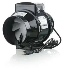
The product described herein is a mixed flow fan for exhaust
ventilation.
Box includes:
1. Fan - 1;
2. Screws and countersinks 4;
3. User's manual;
The fans are compatible with 4” (100 mm), 5” (125 mm),
6” (150 mm).
Understanding the Model Numbers:
The three digit number in all model names indicates the
following:
100 (100 mm) means it is used with 4” duct;
125 (125 mm) means it is used with 5” duct
150 (150 mm) means it is used with 6” duct.
- the basic fan model.
Equipped with an integrated speed switch and a power cord
with a plug for connection to a standard wall socket or with
a terminal box for direct connection to power.
It has the following operation modes (see fig. 5):
“0” turned off, the fan is not operating;
“I” the fan is operating at lowest speed;
“II” the fan is operating at highest speed.
- equipped with an
integrated speed controller with electronic thermostat,
a temperature sensor built into the air duct, and a power cord
with plug (fig. 6);
- equipped with an
integrated speed controller with electronic thermostat,
a remote temperature sensor on the end of a 13 feet
(4 meters) cable, and a power cord with plug (fig. 6);
- equipped with built-in a speed
controller and a power cord with a plug (fig. 7).
The fans are suitable for vertical or horizontal mounting (fig. 1).
If mounting horizontally a duct at least 40 inches (1 meter)
long should be connected to the inlet side of the fan.
If mounting vertically a cap should be installed on the duct
where it exits the roof (fig. 1).
The TT P fans can also be mounted in a parallel or in-line
configuration (fig. 2). Mounting kits for each both
configurations are available (for an extra charge).
The outlet end should always be connected to a duct.
Mounting is shown in fig. 8-17.
The direction of the air must match the direction of the arrow
on the housing. Input: 120 VAC 60 Hz.
Connection to the power source is shown on figure 3 and 4.
VENTS TT PRO_ _
VENTS TT PRO_ _ U(U1, U2)
VENTS TT PRO_ _ Un (U1n, U2n)
VENTS TT PRO_ _ P
The fan is designed for continuous operation.
Protection rating from access to dangerous parts and water
penetration is IPX4.
The fans can be operated at ambient temperatures between
+37°F (+1°C) and +107 °F (+45°C)
(for the details, please, see the manufacturer's catalog).
The fan surfaces need to be cleaned of dirt and dust regularly
by using a soft, wet cloth and mild detergent (Fig. 18-32).
Do not allow liquids to come in contact with the electric motor.
Wipe surfaces dry after cleaning.
fan adjusts air flow depending
on the temperature in the duct.
The "n" index models are equipped with a temperature sensor
on a 13 feet (4 meters) cable.
The terminal box cover incorporates two control dials and
two LED light indicators:
- speed dial
- thermostat dial
- yellow LED light thermostat indicator
- green LED light - power indicator
To increase the thermostat's set point rotate the dial clockwise.
To decrease the set point rotate the dial counter-clockwise.
To increase the fan speed rotate the speed dial clockwise.
To decrease the speed rotate the dial counter-clockwise.
Using the speed dial adjust the minimum required air flow so
it is below the thermostat set point.
The fan switches to low speed when the duct temperature drops
2°F below the thermostat set point.
This prevents possible frequent motor speed switches triggered
by crossing the temperature set point.
Controller Operation
VENTS TT PRO_ _ _ U/U1/U2
TT PRO U Operating mode
Loading ...
Loading ...
Loading ...