DS55MU01
User Manual (English)

DS55MU01
iii
1. Important Safety instructions
[SAFETY WARNING]
• To reduce the risk of re or electric shock, do not expose this product to rain or moisture.
• To prevent injury, this product must be securely attached to the oor/wall in accordance with the installation
instructions.
• To reduce the risk of electric shock, do not remove the back cover
• Refer to qualied service personnel if needed.
Icons used in this manual
[WARNING] means,
If you ignore the warning message, you may be seriously injured or there is a possibility of accident or death.
[CAUTION] means,
If you ignore the caution message, you may be slightly injured or the product may be damaged.
[NOTE] means,
The note helps you understand and use the product safely. Please read the note carefully before using the product.
Warning:
This equipment is compliant with Class A of EN55032/CISPR 32. In a residential environment this equipment may cause
radio interference.
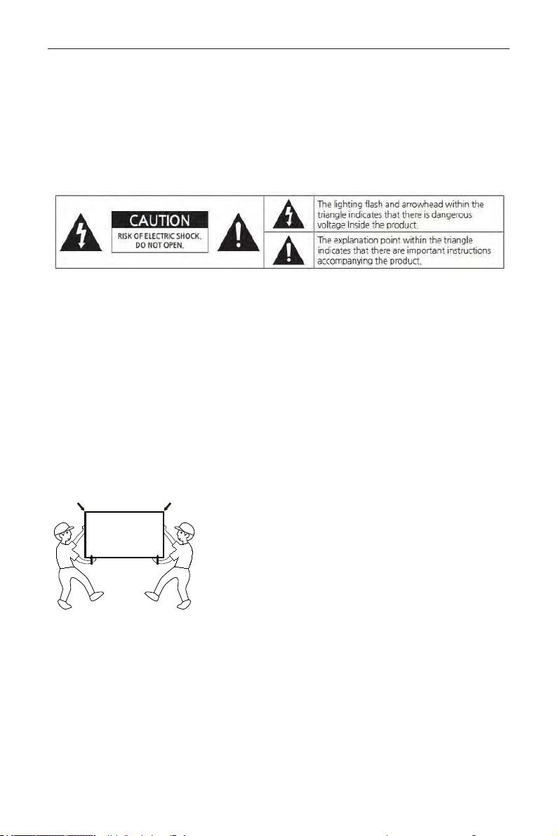
When moving the product, please grab the handles behind and the bottom of the product as shown below picture.
• The product must keep horizontal and upright position when moving.
• Do not hold the corner of the product when you grab the bottom of the product.

DS55MU01
iv
1.1. SAFETY PRECAUTION
Note: The color and design may different by each model and the product specication are subject to change without
notice for performance enhancement.
1.1.1. Power
[Warning]
• Do not use damaged power cord, plug nor loose socket. It may cause electric shock or re.
• Do not connect multiple devices into a single socket. It may cause re due to overheating.
• Do not touch with wet hands when remove or plug the power cord to avoid electric shock.
• Insert the power plug into socket rmly. It may cause re when the connections are unstable.
• Connect the power cord to a grounded wall socket. There is risk of electric shock or injury.
• Do not bend nor pull the power cord and place heavy objects over the power cord. It may occur cord damage
and this may result in re.
• Please clean only with dry cloth when the plug pin or socket are dusty. It may cause re.
[Caution]
• Do not unplug the power plug while the product is operating. It may damage the product due to electric shock.
• Only a power cord specied by product manufacturer are recommended.
• Do not use the power cord from other devices. It may cause electric shock or re.
• Hold the plug itself when unplugging the power plug from the wall socket. If not, there is risk of electric shock or
re.
• Before moving or installing this product, be sure to turn off the power and disconnect the power cord. To turn
this product off completely, you must pull the power plug out of the wall socket. Consequently, the power plug
must be easily and readily accessible at all times.
• The AC inlet and MAIN Power Switch are disconnect device, the location on the apparatus and the function of
the switch shall be described, and the switch shall remain readily operable
.
1.1.2. Installation
[Warning]
• Do not install near any heat sources such as radiators, or other devices that produce heat. It may cause electric
shock or re.
• When mounting a product on the wall, make sure not to install the product by hanging the power and signal
cables on the back of it.
• Consult with your local dealer or specialized engineer to mount the product on the wall, and use the screws and
wall mounts that meet the VESA standard. Any damages or injuries by misuse or using an improper accessory are
not covered by the warranty.
• Leave a 10 cm (4 inches) (minimum) space from the wall for proper ventilation. If not, it may cause re.
• Keep the packing anti-moisture material or vinyl packing out of the reach of children. Anti-moisture material is
harmful if swallowed. If swallowed by mistake, force the patient to vomit and visit the nearest hospital. Additionally,
vinyl packing can cause suffocation. Keep it out of the reach of children.
• Please note than the product must be supported on proper stands or installed according to the manufacturer’s
recommendations. The product that are inappropriately situated on unstable shelves, inclined planes, or vibrating
places, etc., may fall over, resulting in injury.
• To reduce the risk of re or electrical shock, do not expose this product to rain, moisture or other liquids or dust.
It may cause electric shock or re.
• Keep the product away from direct sunlight.
• Keep the product of the reach of children and install on the stable and at place. NEVER allow children to climb
on or play on the product or the furniture and stands on which the product is placed.

DS55MU01
v
[Caution]
• Do not allow an impact shock or any objects to fall into the product, and do not drop anything onto the screen.
• Make sure the product is turned off, unplugged, and all cables have been removed. It may take more than 4 people
to than carry.
• Do not press or put stress on the front panel of the product.
• If the product is installed in a place where the operating conditions considerably, a serious quality problem may
occur due to the surrounding environment. In this case, install the product only after consulting our dealer about
the matter. (Places exposed to microscopic dust, chemicals, too high or low temperature, high humidity, airports or
stations where the product is continuously used.)
1.1.3. Cleaning
[Warning]
• Before cleaning the product, unplug the power cord and wipe gently with a soft cloth to prevent scratching.
• Do not spray water or other liquids directly on the product as electric shock may occur.
[Caution]
• Do not push, rub, or hit the surface with your ngernail or a sharp object, as this may result in scratches on the
screen and image distortions.
• Do not use any chemicals, such as waxes, benzene, alcohol, thinners, insecticides, air fresheners, or lubricants, as
these may damage the screen’s nish and cause discoloration.
• Do not spray liquid onto the surface. If water enters the product, it may result in re, electric shock, or malfunction.
1.1.4. General Usage
[Warning]
• To reduce the risk of electric shock, do not open the cover or back. No user serviceable parts inside. Refer to
qualied service personnel.
• Before moving or lifting the product, disconnect the power cord and all cables.
• The route cords and cables connected to the product so that they cannot be tripped over, pulled or grabbed.
• Do not stick metal objects or any other conductive material into the power cord. Do not touch the end of the
power cord while it is plugged in. It may result in re, electric shock.
• Unplug this product during lightning storms or when unused for long periods of time.
• Do not block any ventilation openings. Install in accordance with the manufacturer’s instructions.
• To reduce the risk of re or electrical shock, do not expose this product to rain, moisture or other liquids. Do not
touch the product with wet hands. Do not install this product near ammable objects such as gasoline or candles,
or expose to direct air conditioning.
• NEVER allow children to climb on or play on the product or the furniture on which it is placed. It may cause
severe injury to children.
• Use only with a cart, stand, tripod, bracket, or table specied by the manufacturer, or sold with the product. When
a cart is used, be careful when moving the cart/product combination to avoid injury from tip-over.
• Install where it cannot be pushed, pulled over or knocked down.
• It is recommended to move the product in the box or packing material that originally came in.
• When holding the product, the screen should face away from you to avoid damage.
[Caution]
• If a xed image displays on the screen for a long period of time, it will be imprinted and become a permanent
disgurement on the screen. This is image burn or burn-in and not covered by the warranty.
• Avoid displaying a xed image on the screen for a long period of time to prevent image burn. Recommend to
power off or set the screen saver mode when not in use. Be aware that the image burn symptom cannot be
repaired and is not covered under warranty.
• When watching the screen, take 5 to 15 minute breaks every hour. Viewing screen for a long period of time may
cause fatigue or eye strain.
DS55MU01
vi
• Take care not to touch the ventilation openings. When watching the screen for a long period, the ventilation
openings may become hot. This does not affect the performance of the product or cause defects in the product.
• Do not install this product on a wall if it could be exposed to oil or oil mist. This may damage the product and
cause it to fall.
• To install batteries in remote control, open the battery cover, replace batteries matching (+) and (-) ends to the
label inside the compartment, and close the battery cover. Failure to match the correct polarities of the battery
may cause the battery to burst or leak, resulting in re, personal injury, or ambient pollution.
• To prevent to swallow the small accessories for children, keep the accessories out of the reach of children.
• The product must keep horizontal and upright position when moving. Hold the top and bottom of the frame
rmly.
• When attaching the wall mount to the set, place the screen facing down on a cushioned table or at surface to
protect the screen from scratches by more than 2 people,
• Make sure that the screws are fastened tightly. (If they are not fastened securely enough, it may tilt forward after
being installed.)
1.2. MAINTENANCE
1.2.1. Cleaning
[Warning]
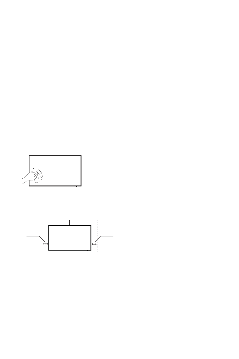
• When cleaning, unplug the power cord and wipe gently with a soft dry cloth to prevent scratching.
• Do not spray water or other liquids directly on the screen as electric shock may occur.
• Do not clean with chemicals such as alcohol, thinners, or benzene.
1.2.2. Installation
• Leave a 10 cm (4 inches) (minimum) space from the wall for proper ventilation. If not, it may cause re or
malfunction due to the high temperature product inside.
[When mounting on a wall]
10cm (3.93 inches)
10cm
(3.93 inches)
10cm
(3.93 inches)
1.2.3. Panel
• Avoid displaying a xed image on the screen for a long period of time (2 or more hours for LCD) to prevent
image burn. Recommend to power off or set the power saving mode or screen saver when not in use.
• Due to technological constraints of the Panel manufacturer, the images generated by this product may appear
either brighter or darker than normal by appr. 1ppm (parts per million) pixel.
• The number of sub-pixels of a panel by size: The number of Sub-Pixels = Max. Horizontal Resolution x Max.
Vertical Resolution x 3.
• For example, if the maximum resolution is 3840 x 2160, the number of sub-pixels is 1920 x 1080 x 3 =
12,441,600.

DS55MU01
vii
Table Of Contents
1. Unpacking and Installation 1
1.1. Unpacking ...........................................1
1.2. Package Contents ...........................1
1.3. Installation Notes ............................1
1.4. Mounting on a Wall .......................2
2. Parts and Functions 3
2.1. Control Panel ....................................3
2.2. Input/Output Terminals ...............4
2.3. Using of Remote sensor and
power indicator ...............................6
2.4. Remote Control ..............................7
3. Connecting External Equipment 10
3.1. Connecting External Equipment
(DVD/VCR/VCD) .......................10
3.2. Connecting a PC ..........................10
3.3. Connecting Audio Equipment 1 1
3.4. Connecting Multiple Displays in
a Daisy-chain Conguration . . 11
3.5. IR connection .................................11
3.6. IR Pass-through Connection . 12
4. Operation 13
4.1. Watch the Connected Video
Source ................................................13
4.2. Change Picture Format ............13
4.3. Overview .........................................13
4.4. Media Player introduction: ......14
4.5. Browser manual ............................15
4.6. PDF reader play ............................17
4.7. CMS .....................................................19
4.8. Custom App ...................................19
5. Signage display 20
5.1. Setting ................................................20
5.2. Ethernet ............................................20
5.3. Proxy ...................................................21
5.4. Signage Display ..............................21
5.5. System Tools ...................................29
5.6. Clone Media File ..........................30
5.7. Display ..............................................31
5.8. Apps ....................................................31
5.9. Security ..............................................31
5.10. Date & time ....................................31
5.11. Developer options ......................31
5.12. About .................................................31
5.13. Supplementary ..............................32
6. OSD Menu 34
6.1. Navigating the OSD Menu.....34
6.2. OSD Menu Overview ..............35
7. Supported Media Formats 41
8. Input Mode 44
9. Cleaning and Troubleshooting 46
9.1. Cleaning ............................................ 46
9.2. Troubleshooting ............................47
10. TechnicalSpecications 49
DS55MU01
1
1. Unpacking and Installation
1.1. Unpacking
• This product is packed in a carton, together with the standard accessories.
• Any other optional accessories will be packed separately.
• Due to the size and weight of this display it is recommended for two people to move it.
• After opening the carton, ensure that the contents are complete and in good condition.
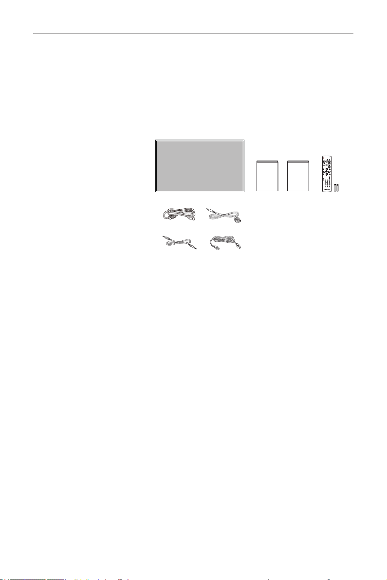
1.2. Package Contents
Please verify that you received the following items with your package content:
• LCD display
• User Manual
• Warranty Card
• Remote control and AAA Batteries
• Power Cord
• RS232 Cable
• RS232 Daisy Chain Cable
• HDMI Cable
* The supplied power cord varies depending on destination.
Power Cord
User Manual
RS232 Daisy Chain Cable
FORMAT
SOURCE
INFOLIST
OPTIONSADJUST
VOL
NORMAL
ID
ID SET ENTER
RS232 Cable
HDMI Cable
Warranty Card
Remote Control
and AAA Batteries
NOTES:
• For all other regions, apply a power cord that conforms to the AC voltage of the power socket and has been
approved by and complies with the safety regulations of the particular country (Type H05W-F, 2G or 3G, 0.75 or
1 mm
2
should be used).
• You might like to save the package box and packing material for shipping the display.
1.3. Installation Notes
• Due to the high power consumption, always use the plug exclusively designed for this product. If an extended line
is required, please consult your service agent.
• The product should be installed on a at surface to avoid tipping. The distance between the back of the product
and the wall should be maintained for proper ventilation. Avoid installing the product in the kitchen, bathroom or
any other places with high humidity so as not to shorten the service life of the electronic components.
• The product can normally operate only under 3000m in altitude. In installations at altitudes above 3000m, some
abnormalities may be experienced.
DS55MU01
2
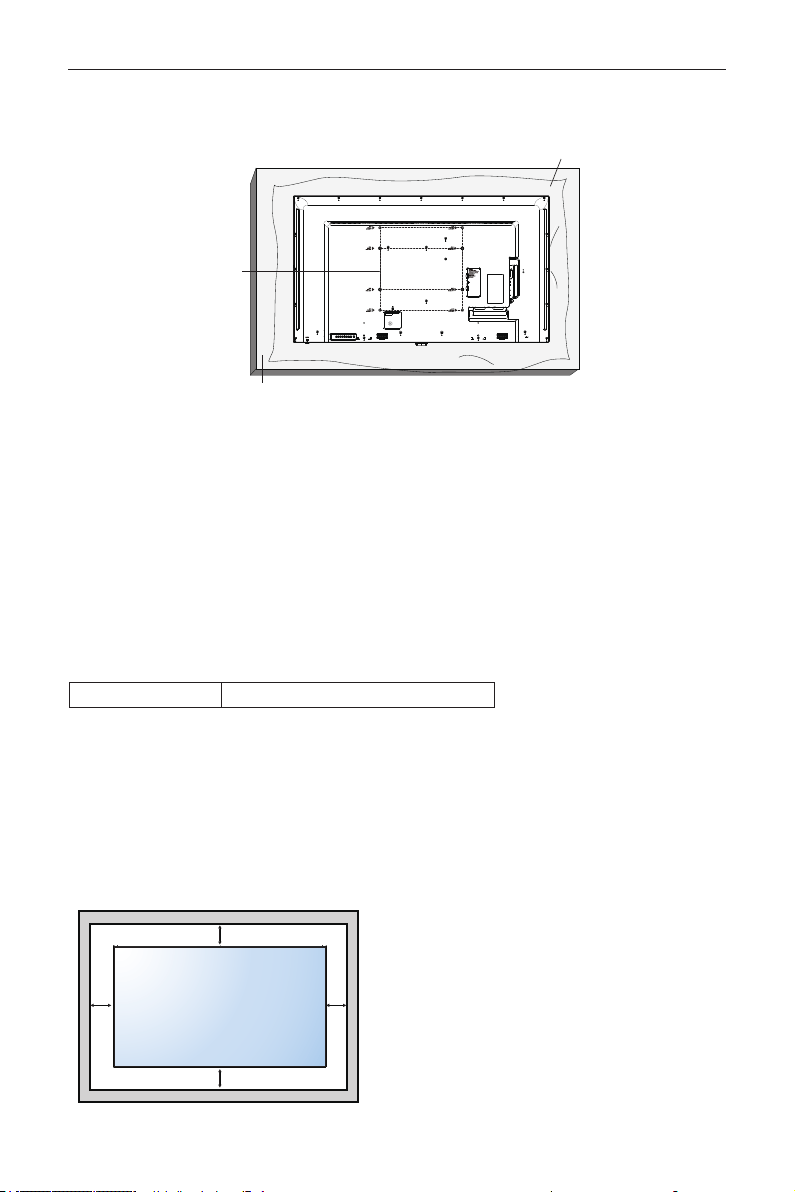
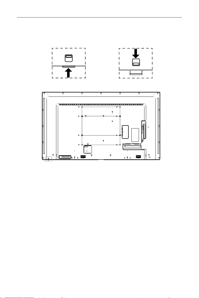
1.4. Mounting on a Wall
To mount this display to a wall, you will have to obtain a standard wall-mounting kit (commercially available). We
recommend using a mounting interface that complies with TUV-GS and/or UL1678 standard in North America.
Protective Sheet
VESA Grid
Table
1. Lay a protective sheet on a table, which was wrapped around the display when it was packaged, beneath the screen
surface so as not to scratch the screen face.
2. Ensure you have all accessories for mounting this display (wall mount, ceiling mount, table stand, etc).
3. Follow the instructions that come with the base mounting kit. Failure to follow correct mounting procedures could
result in damage to the equipment or injury to the user or installer. Product warranty does not cover damage
caused by improper installation.
4. For the wall-mounting kit, use M6 mounting screws (having a length 10 mm longer than the thickness of the
mounting bracket) and tighten them securely.
5. Unit without base weight= 24.8 kg. The equipment and its associated mounting means still remain secure during
the test. For use only with UL Listed Wall Mount Bracket with minimum weight/load: 24.8 kg.
6. Portrait is not allowed.
1.4.1. VESA Grid
DS55MU01 400(H) x 400(V) mm, 400(H) x 200(V)
Caution:
To prevent the display from falling:
• For wall or ceiling installation, we recommend installing the display with metal brackets which are commercially
available. For detailed installation instructions, refer to the guide received with the respective bracket.
• To lessen the probability of injury and damage resulting from fall of the display in case of earthquake or other
natural disaster, be sure to consult the bracket manufacturer for installation location.
Ventilation Requirements for enclosure locating
To allow heat to disperse, leave space between surrounding objects as shown in the diagram below.
100 mm 100 mm
100 mm
100 mm
DS55MU01
3
2. Parts and Functions
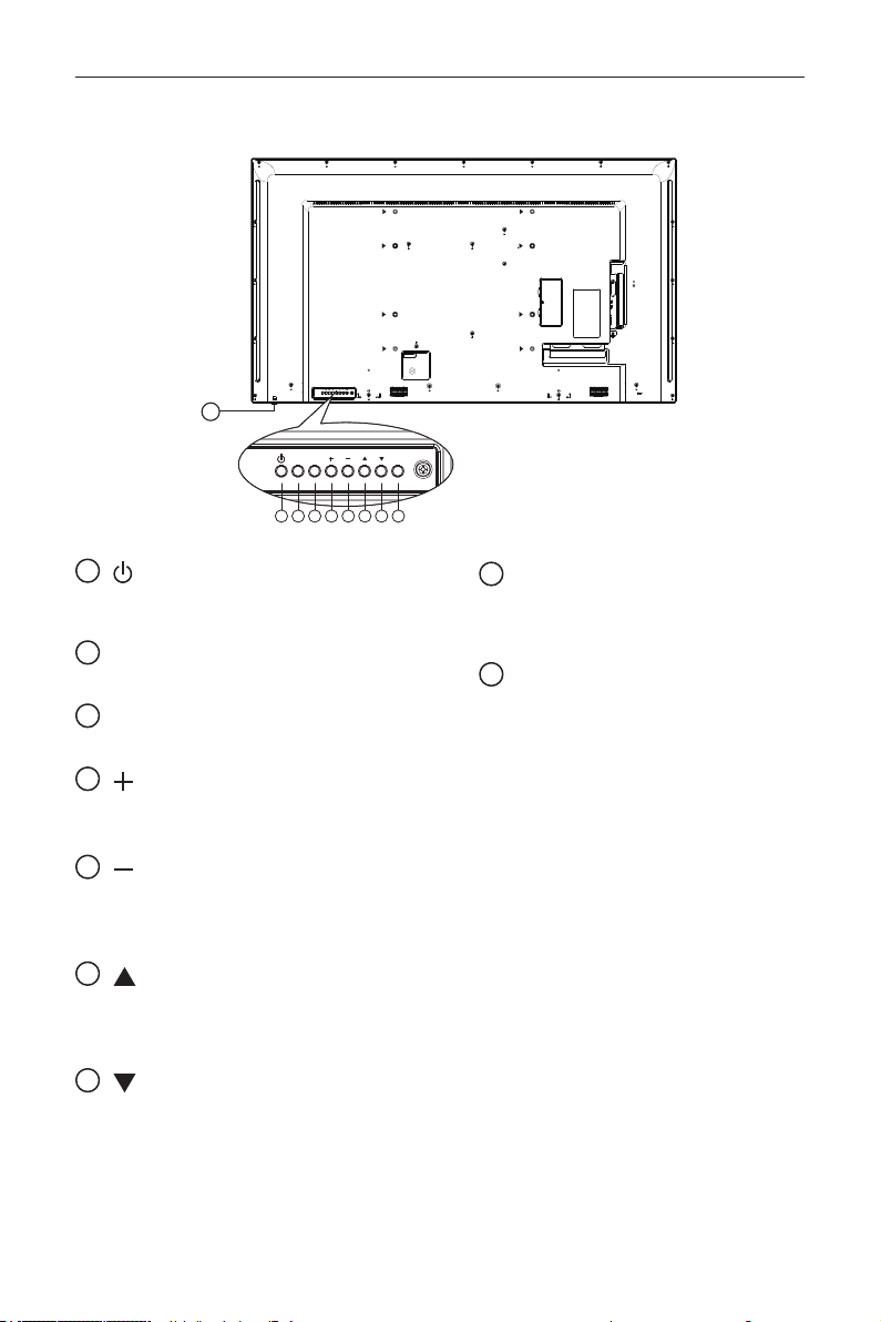
2.1. Control Panel
MUTE INPUT
MENU
1 2 3 4 5 6 7 8
9
1
[
] button
Use this button to turn the display on or put the
display to standby.
2
[MUTE] button
Switch the audio mute ON/OFF.
3
[INPUT] button
Choose the input source.
4
[
] button
• Increase the volume
• Enter into submenu while OSD menu is on
5
[
] button
• Decrease the volume
• Back to previous menu while OSD menu is
on
6
[
] button
• Move the highlight bar up to adjust the
selected item while OSD menu is on
• Increase the adjustment while adjust value.
7
[
] button
• Move the highlight bar down to adjust the
selected item while OSD menu is on.
• Decrease the adjustment while adjust value.
8
[MENU] button
Return to previous menu while OSD menu is
on, or to activate the OSD menu when OSD
menu is off.
9
Remote control sensor and power status
indicator
• Receives command signals from the
remote control.
• Indicates the operating status of the display
without OPS:
• Lights green when the display is turned
on
• Lights red when the display is in standby
mode
• When {SCHEDULE} is enabled, the light
blinks green and red
• If the light blinks red, it indicates that a
failure has been detected
• Lights off when the main power of the
display is turned off
* Using IR sensor cable for better remote
control performance. (Please refer to the
instructions of 3.5)
DS55MU01
4
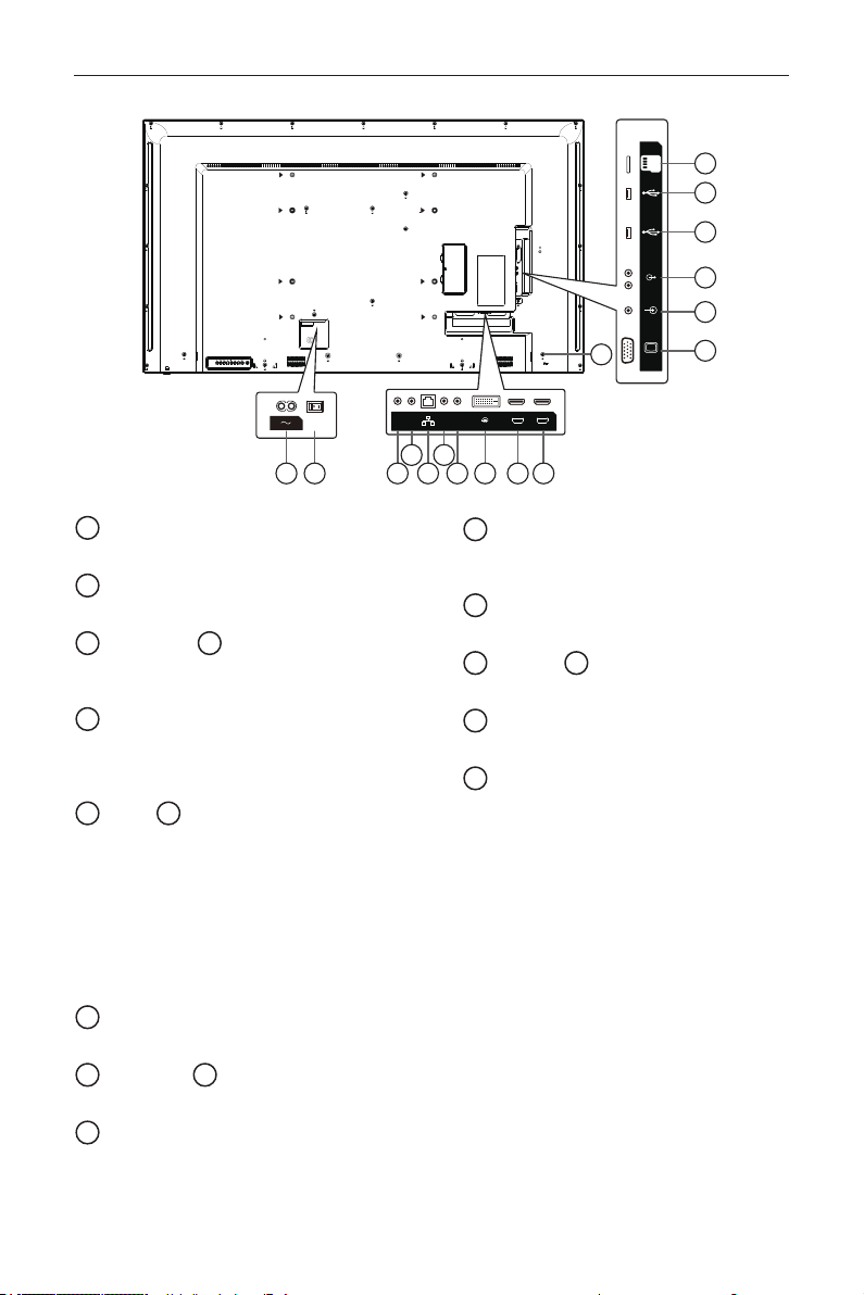
2.2. Input/Output Terminals
PC LINE IN
VGA IN
USB-1
USB-2
AUDIO OUT
MICRO SD
11
17
12
13
15
14
16
1 32 5
4 6
7 98 10
HDMI 1 IN HDMI 2 IN
IR-IN IR-OUT
RJ45
RS232
OUT
RS232
IN
DVI IN
1
AC IN
AC power input from the wall outlet.
2
MAIN POWER SWITCH
Switch the main power on/off.
3
RS232C IN /
4
RS232C OUT
RS232C network input / output for the loop-
through function.
5
RJ-45
LAN control function for the use of remote
control signal from control center. and internal
function.
6
IR IN /
7
IR OUT
IR signal input / output for the loop-through
function.
NOTES:
• This display’s remote control sensor will
stop working if the jack [IR IN] is connected.
• To remotely control your A/V device via
this display, refer to page 10 for or IR Pass
Through connection.
8
DVI IN
DVI video input.
9
HDMI1 IN /
10
HDMI2 IN
HDMI video/audio input.
11
VGA IN (D-Sub)
VGA video input.
12
PC LINE IN
Audio input for VGA source (3.5mm stereo
phone).
13
AUDIO OUT
Audio output to external AV device.
14
USB 2.0 /
15
USB 3.0 PORT
Connect your USB storage device
16
MICRO SD CARD
Connect your MICRO SD CARD.
17
SECURITY LOCK
Used for security and theft prevention.
DS55MU01
5
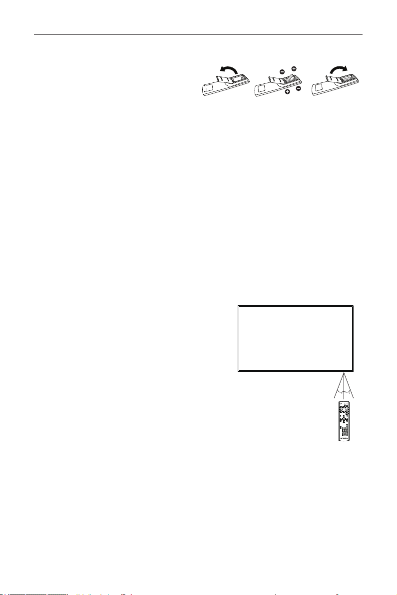
2.2.1. Inserting the batteries in the remote control
The remote control is powered by two 1.5V AAA batteries.
To install or replace batteries:
1. Press and then slide the cover to open it.
2. Align the batteries according to the (+) and (–)
indications inside the battery compartment.
3. Replace the cover.
Caution:
The incorrect use of batteries can result in leaks or bursting. Be sure to follow these instructions:
• Place “AAA” batteries matching the (+) and (–) signs on each battery to the (+) and (–) signs of the battery
compartment.
• Do not mix battery types.
• Do not combine new batteries with used ones. It causes shorter life or leakage of batteries.
• Remove the dead batteries immediately to prevent them from liquid leaking in the battery compartment. Don’t
touch exposed battery acid, as it can damage your skin.
NOTE: If you do not intend to use the remote control for a long period, remove the batteries.
2.2.2. Handling the remote control
• Do not subject to strong shock.
• Do not allow water or other liquid to splash the remote control. If the remote control gets wet, wipe it dry
immediately.
• Avoid exposure to heat and steam.
• Other than to install the batteries, do not open the remote control.
2.2.3. Operating range of the remote control
Point the top of the remote control toward the display’s remote control
sensor when pressing a button.
Use the remote control within a distance of less than 5m/16ft from
the display’s sensor, and a horizontal and vertical angle of less than 30
degrees.
NOTE: The remote control may not function properly when
the remote control sensor on the display is under direct
sunlight or strong illumination, or when there is an obstacle
in the path of signal transmission.
3030
DS55MU01
6
2.3. Using of Remote sensor and power indicator
1. Push down the lens to have better remote control performance and easy to observe the light information of
power status
2. Pull up the lens before mounting the display for video wall application
3. Pull/Push the lens until hearing the click sound
Push up to collapse the lens Push down to extend the lens
DS55MU01
7
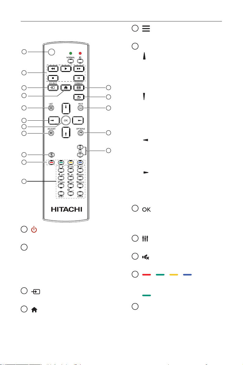
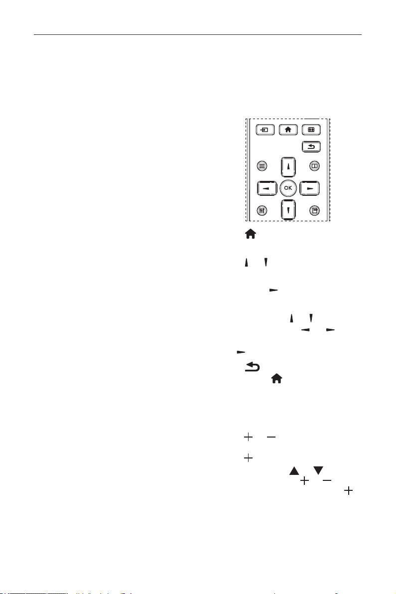
2.4. Remote Control
2.4.1. General functions
1
2
3
4
5
6
7
8
10
9
12
14
15
11
13
16
1
[
] POWER button
Power ON/OFF.
2
[PLAY] buttons
Control playback of media les.(for Media Input
only)
Freeze feature
Pause: Freeze hot key for all inputs content.
Play: Unfreeze hot key for all input content.
3
[
] SOURCE button
Root Menu: Go to Video source OSD.
4
[
] HOME button
Root Menu: Go to Main Menu OSD.
Others: Exit OSD.
5
[
] LIST button
No function.
6
NAVIGATION buttons
[
]
Root Menu: Go to Smart picture OSD.
Main Menu: Move the highlight bar up to adjust
the selected item.
IR Daisy Chain Menu: Increase controlled
Group ID number.
[
]
Root Menu: Go to Audio source OSD.
Main Menu: Move the highlight bar down to
adjust the selected item.
IR Daisy Chain Menu: Decrease controlled
Group ID number.
[
]
Main Menu: go to previous level menu.
Source Menu: Exit source menu.
Volume Menu: Decrease Audio Volume.
[
]
Main Menu: go to next level menu or set
selected option.
Source Menu: Go to selected source.
Volume Menu: Increase Audio Volume.
7
[
] button
Root Menu: Go to IR daisy chain OSD in
Primary/Secondary mode.
Main Menu: Conrm an entry or selection.
8
[
] ADJUST button
Go to Auto Adjust OSD for VGA only.
9
[
] MUTE button
Toggle Audio Mute/Unmute.
10
[
] [ ] [ ] [ ] COLOR
buttons
Choose tasks or options.(for Media Input only)
[
]
Hot key for Window selection function.
11
[Number/ ID SET/ ENTER] button
Enter text for network setting.
Press to set the display ID. Refer to 2.3.2. ID
Remote Control for more detail.
DS55MU01
8
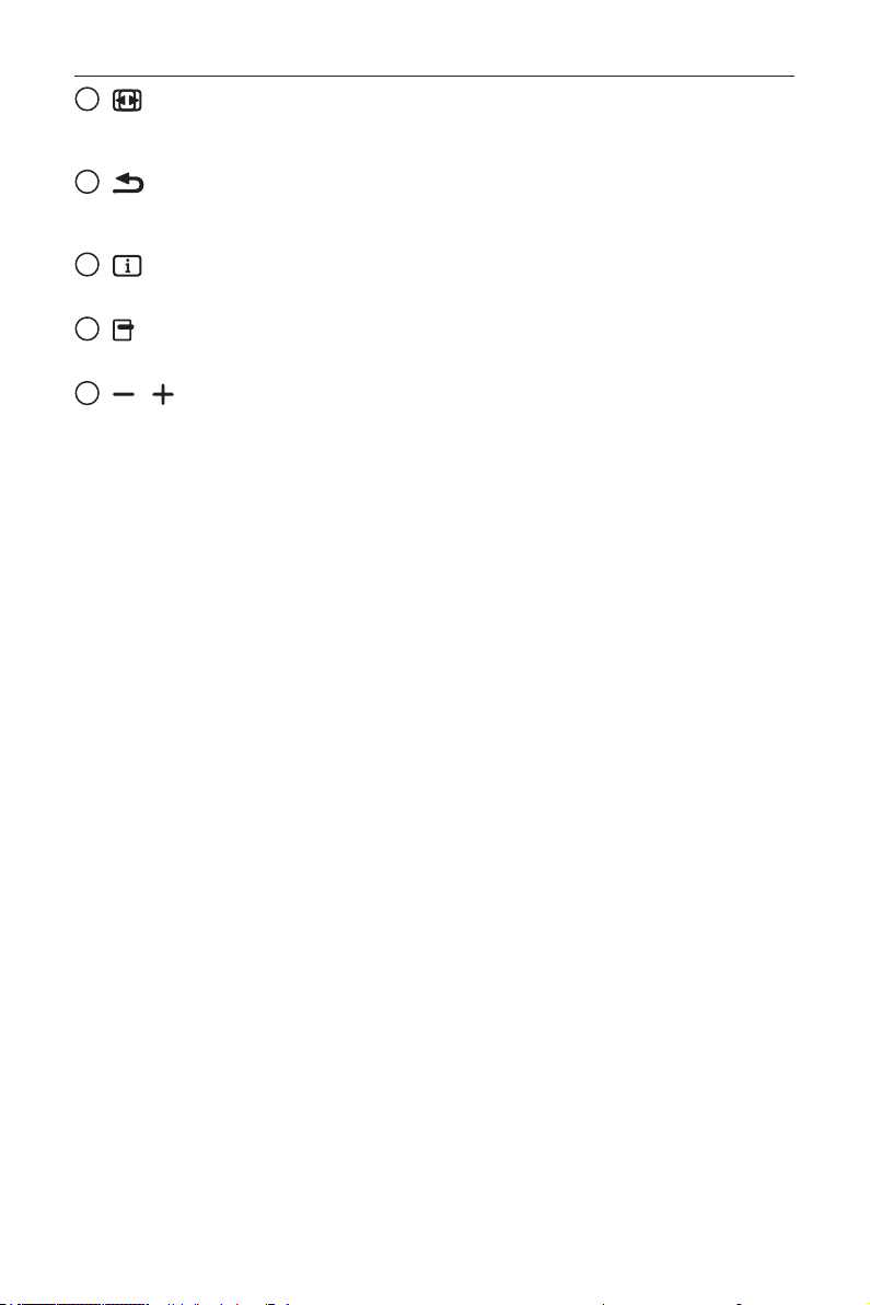
12
[
] FORMAT button
Change Image Zoom Mode [Full][4:3][Real][21:9]
[Custom].
13
[
] BACK button
Return to the previous menu page or exit from
the previous function.
14
[
] INFO button
Show Information OSD
15
[
] OPTIONS button
No function.
16
[
] [ ] VOLUME button
Adjust volume.
DS55MU01
9
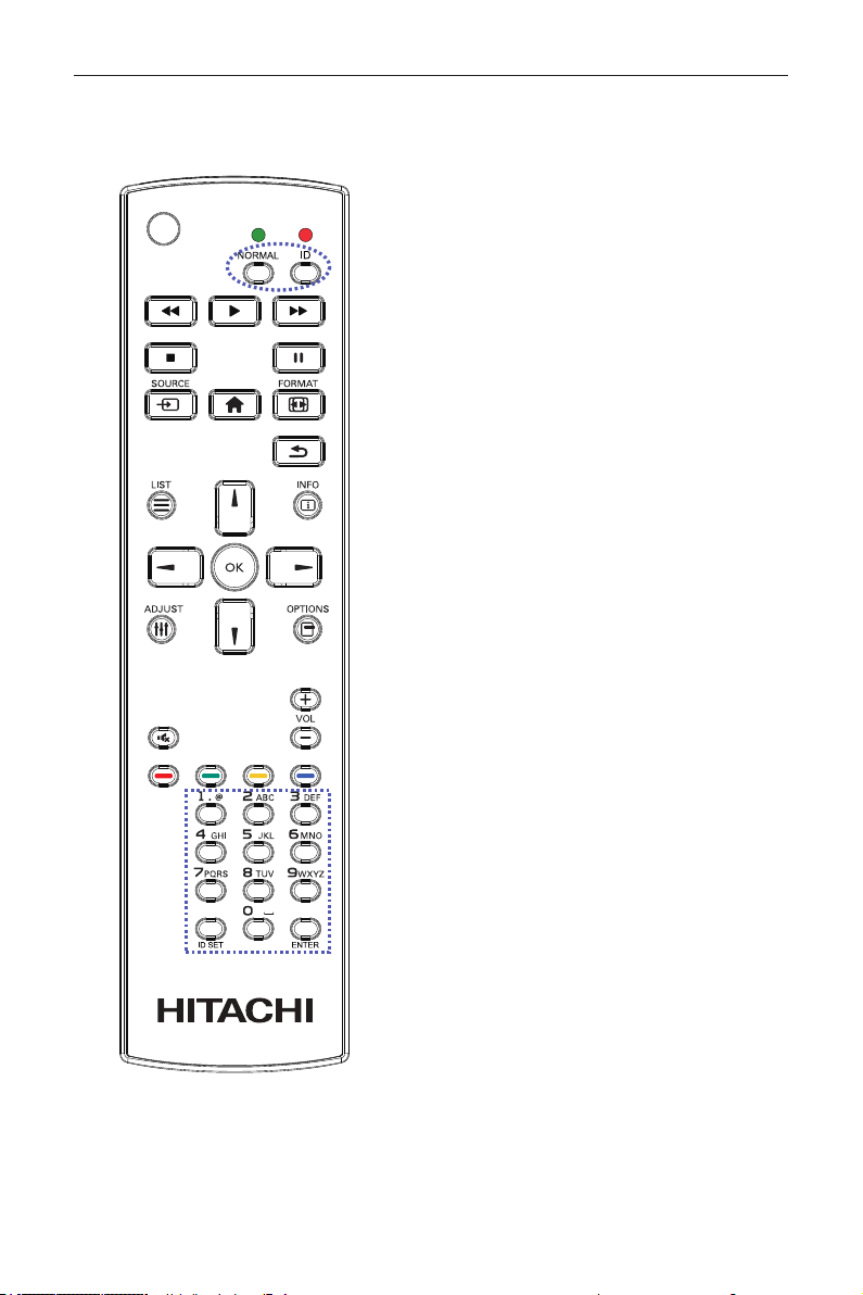
2.4.2. ID Remote Control
You can set the remote control ID when you want
to use this remote control on one of several different
displays.
Press [ID] button. The red LED blinks twice.
1. Press [ID SET] button for more than 1 second to
enter the ID Mode. The red LED lights up.
Press the [ID SET] button again will exit the ID
Mode. The red LED lights off.
Press the digit numbers [0] ~ [9] to select the display
you want to control.
For example: press [0] and [1] for display No.1, press
[1] and [1] for display No.11.
The numbers available are from [01] ~ [255].
2. Not pressing any button within 10 seconds will
exit the ID Mode.
3. If an error pressing of buttons other than the
digits occured, wait 1 second after the red LED
lights off and then lights up again, then press the
correct digits again.
4. Press [ENTER] button to conrm. The red LED
blinks twice and then lights off.
NOTE:
• Press [NORMAL] button. The green LED
blinks twice, indicating the display is in normal
operation.
• It is necessary to set up the ID number for each
display before selecting its ID number.
DS55MU01
10
3. Connecting External Equipment
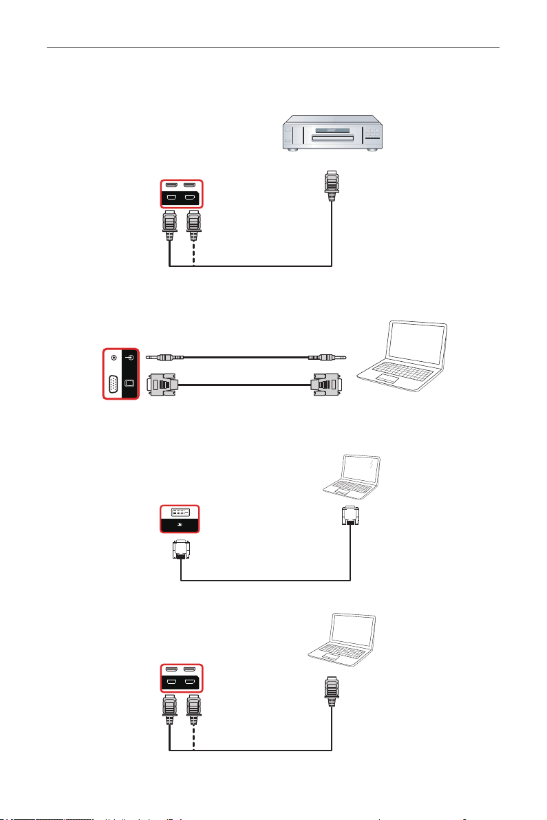
3.1. Connecting External Equipment (DVD/VCR/VCD)
3.1.1. Using HDMI video input
DVD / VCR / VCD
HDMI 1 IN HDMI 2 IN
HDMI Out
[HDMI IN]
3.2. Connecting a PC
3.2.1. Using VGA input
PC
PC LINE IN
VGA IN
[VGA IN]
[VGA AUDIO IN]
VGA Out
D-Sub 15 pin
Audio Out
3.2.2. Using DVI input
PC
DVI Out
[DVI IN]
DVI IN
3.2.3. Using HDMI input
PC
HDMI 1 IN HDMI 2 IN
HDMI Out
[HDMI IN]
DS55MU01
11
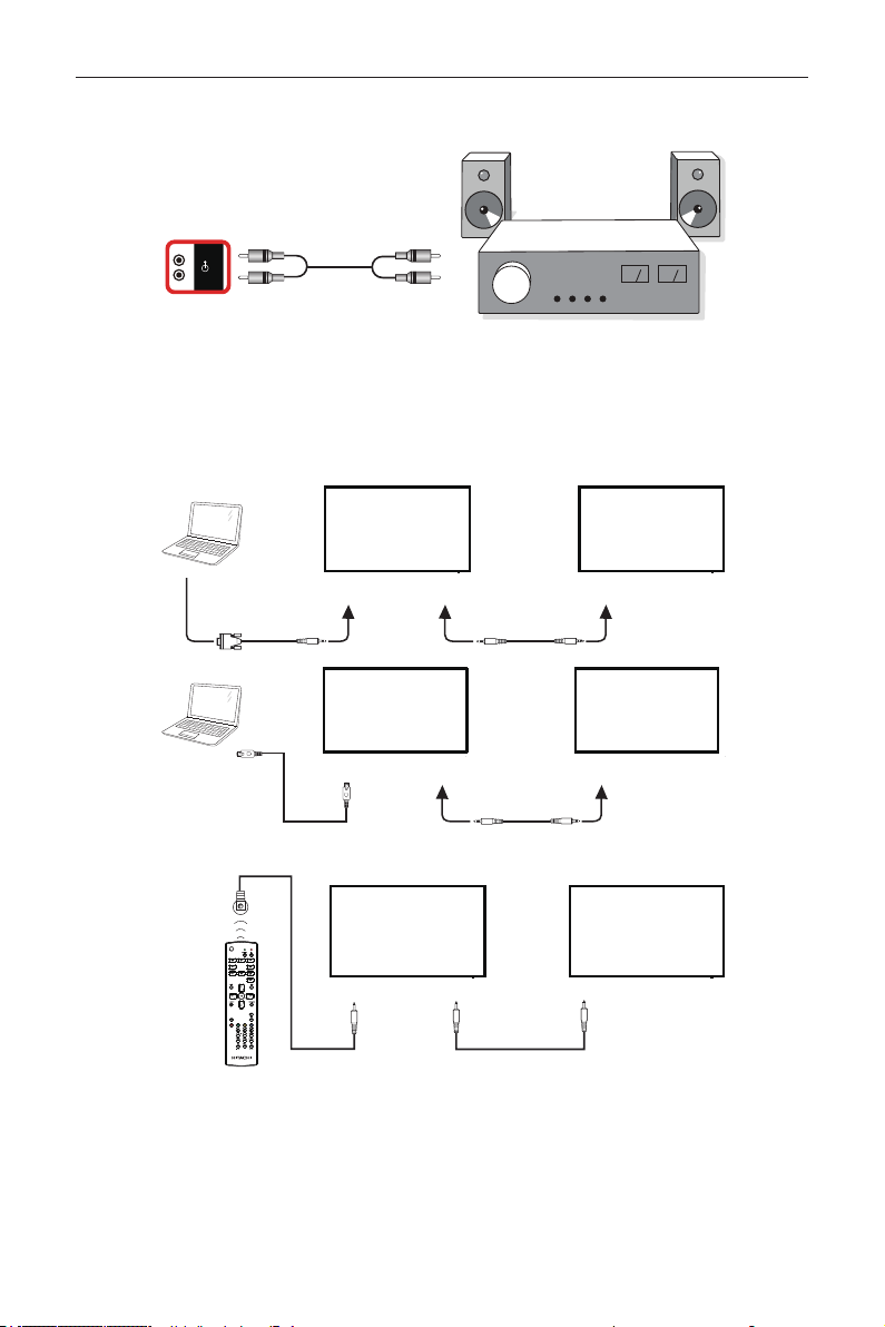
3.3. Connecting Audio Equipment
3.3.1. Connecting an external audio device
AUDIO OUT
Stereo Amplifier
[AUDIO OUT] Audio In
3.4. Connecting Multiple Displays in a Daisy-chain Configuration
You can interconnect multiple displays to create a daisy-chain conguration for applications such as a menu board.
3.4.1. Display control connection
Connect the [RS232 OUT] connector of DISPLAY 1 to the [RS232 IN] connector of DISPLAY 2.
DISPLAY 1
PC
DISPLAY 2
[RS-232C IN]
[RS-232C]
[RS-232C OUT] [RS-232C IN]
DISPLAY 1
PC
DISPLAY 2
[RJ-45] [RS-232C OUT] [RS-232C IN]
[RJ-45]
3.5. IR connection
[IR IN]
External
IR Receiver
[IR IN]
[IR OUT]
DISPLAY 1
DISPLAY2
DS55MU01
12
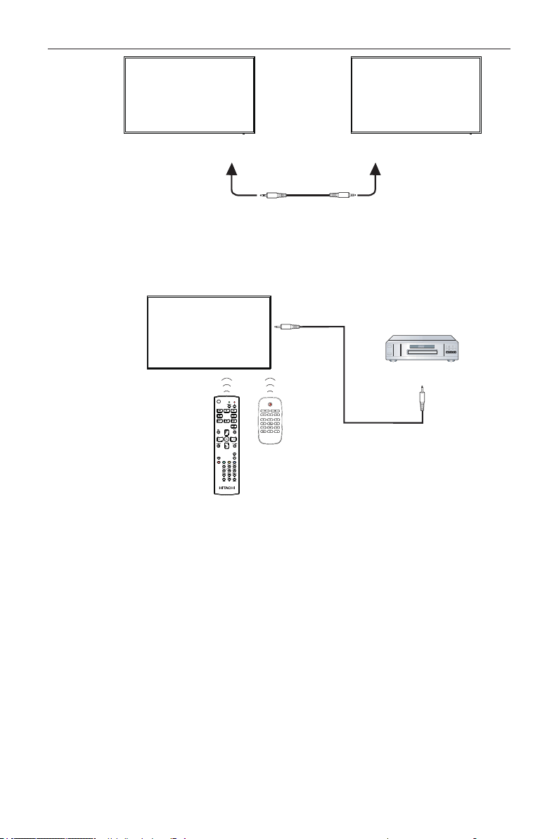
DISPLAY 1 DISPLAY 2
[RS-232C OUT] [RS-232C IN]
NOTE:
1. This display’s remote control sensor will stop working if the [IR IN] is connected.
2. IR loop through connection can support up to 9 displays.
3. IR in daisy chain via RS232 connection can support up to 9 displays.
3.6. IR Pass-through Connection
DVD / VCR / VCD
(DVD / VCR / VCD)
Remote Control
[IR OUT]
[IR IN]
DS55MU01
13
4. Operation
NOTE: The control button described in this
section is mainly on the remote control
unless specied otherwise.
4.1. Watch the Connected Video
Source
1. Press
[
]
SOURCE button.
2. Press
[
]
or
[
]
button to choose a device, then
press
[
]
button.
4.2. Change Picture Format
You can change the picture format to suit the video
source. Each video source has its available picture
formats.
The available picture formats depend on the video
source:
1. Press
[
]
FORMAT button.
• PC mode: {Full} / {4:3} / {1:1} / {21:9}/
{Custom}.
• Video mode: {Full} / {4:3} / {1:1} / {21:9}/
{Custom}.
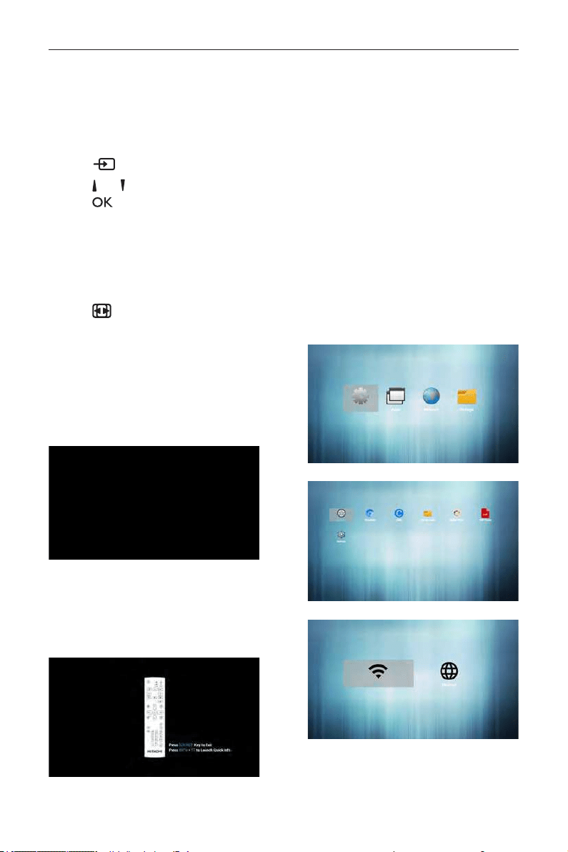
4.3. Overview
1. Android PD launcher:
• Android PD launcher is black page, as
below:
• Every apps leave by press back key, the
screen will go to android PD launcher.
• When you return to android PD launcher,
the screen will show hint image, the hint
image only show 5 second, as below:
• The hint image will notify you can press
source key to change source.
2. Admin mode:
• You can press “Home + 1668” to enter
admin mode. Please make sure you see the
Home OSD menu after “Home” is pressed,
and then press 1668 in sequence. Two
continuous “Home” keys will not be a valid
hotkey.
• Admin mode will show four icons:
“Settings”, “Apps”, “Network” and
“Storage”.
• When you leave admin mode, system will
return to last source.
1)Home page of admin mode, this page has
four items: “Settings”, “Apps”, “Network” and
“Storage”.
Settings : go to settings app.
Applications : show all apps.
Network : set Ethernet and Mobile network
(optional).
Storage : display current PD Android storage
information.
2.) Application page:
3
)
Network page
4
)
Ethernet page
DS55MU01
14
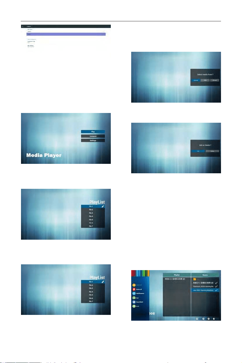
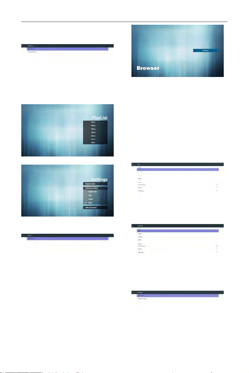
4.4. Media Player introduction:
1. Home page of MediaPlayer app, this page has
three items: “Play”, “Compose” and “Settings”.
Play : select playlist to play.
Compose: edit playlist.
Settings: setting play properties.
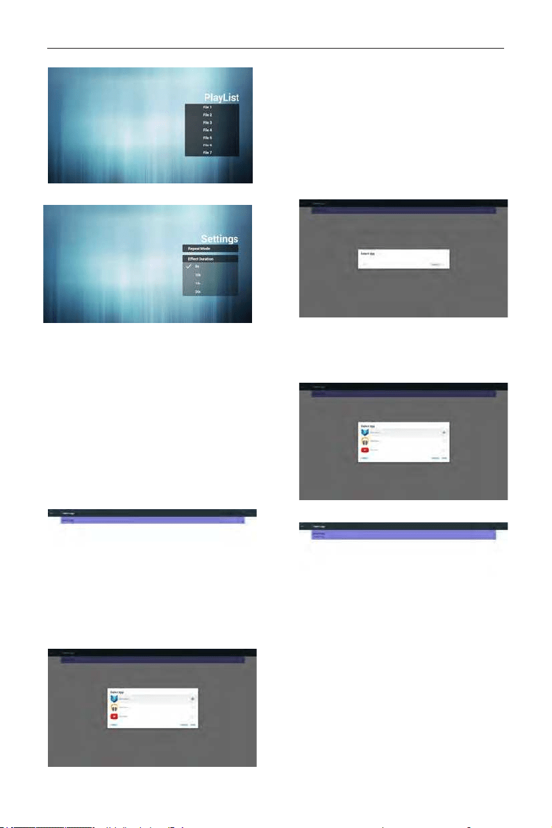
2. Select “Play” on home page, rst you should
choose one playlist to play between FILE 1 and
FILE 7.
The pencil icon means the playlist is non-empty.
3. Select “Compose” on home page, rst you
should choose one playlist to edit between FILE
1 and FILE 7.
The pencil icon means the playlist is non-empty.
4. If an empty playlist is chosen, the app will guide
you to select the media source.
All media les should be placed in /signage/ of
directory.
For example,
- videos in signage/video/
- photos in signage/photo/
- music in signage/music/
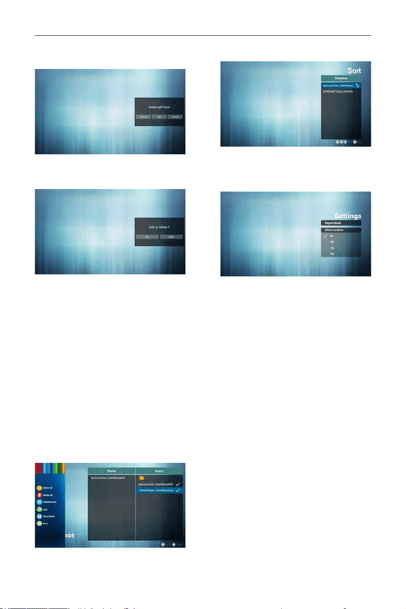
5. You could edit or delete a non-empty playlist, just
choose the desired playlist which is with pencil
icon.
6. Once you start to edit a playlist, you will see
below screen.
Source - les in storage.
Playlist – les in playlist.
There are 4 icons which map to the keys of
remote controller. Option key – launch slide bar
Play key – play media le.
Info key – show media info.
Ok key – select/unselect le.
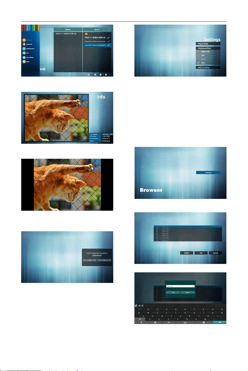
6-1 In the slide bar, it helps you to do the
following:
- select all : select all storage les.
- delete all : delete all playlist les.
- add/remove : update playlist from source.
- sort : sort playlist.
- save/abort : save or abort playlist.
- back : return.
7. If you choose “Sort” in the slide bar, you can
change the order of les one by one.
DS55MU01
15
8. Press info key after you choose desired le, you
will get the detail information.
9. Press play key after you choose desired le, you
will play the media le directly.
10. If you make a playlist with all images les, before
saving, the app will ask you if you want to hava
background music while slideshow playing.
11. Select “Settings” on home page, this page has
three parts, “Repeat Mode”, “Slideshow Effect”
and “Effect Duration”.
- Repeat Mode : play mode.
- Slideshow Effect : photo slideshow effect.
- Effect Duration : photo effect duration.
12. Media Hotkey
- Play : Playback le.
- Pause: Pause le.
- Fast forward: forward 20 second.
- Rewind: back 20 second.
- Stop: Stop le and return to start. If the gif le, it
like the pause.
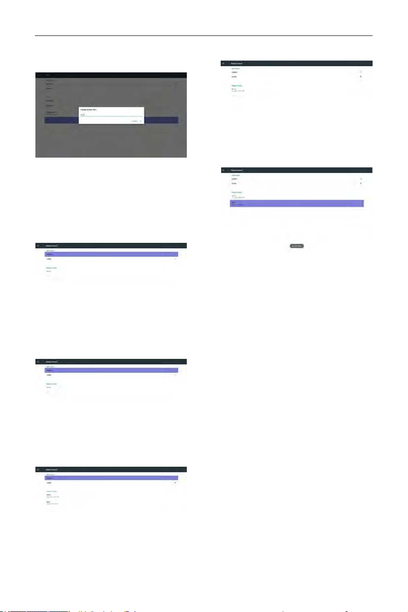
4.5. Browser manual
1. Home page of Browser app, this page has one
item: “Settings”.
Press Settings then enter next page.
2. Users can choose 1~7.
Press any one will show a dialog.
3. Enter url and press OK then data will save on List
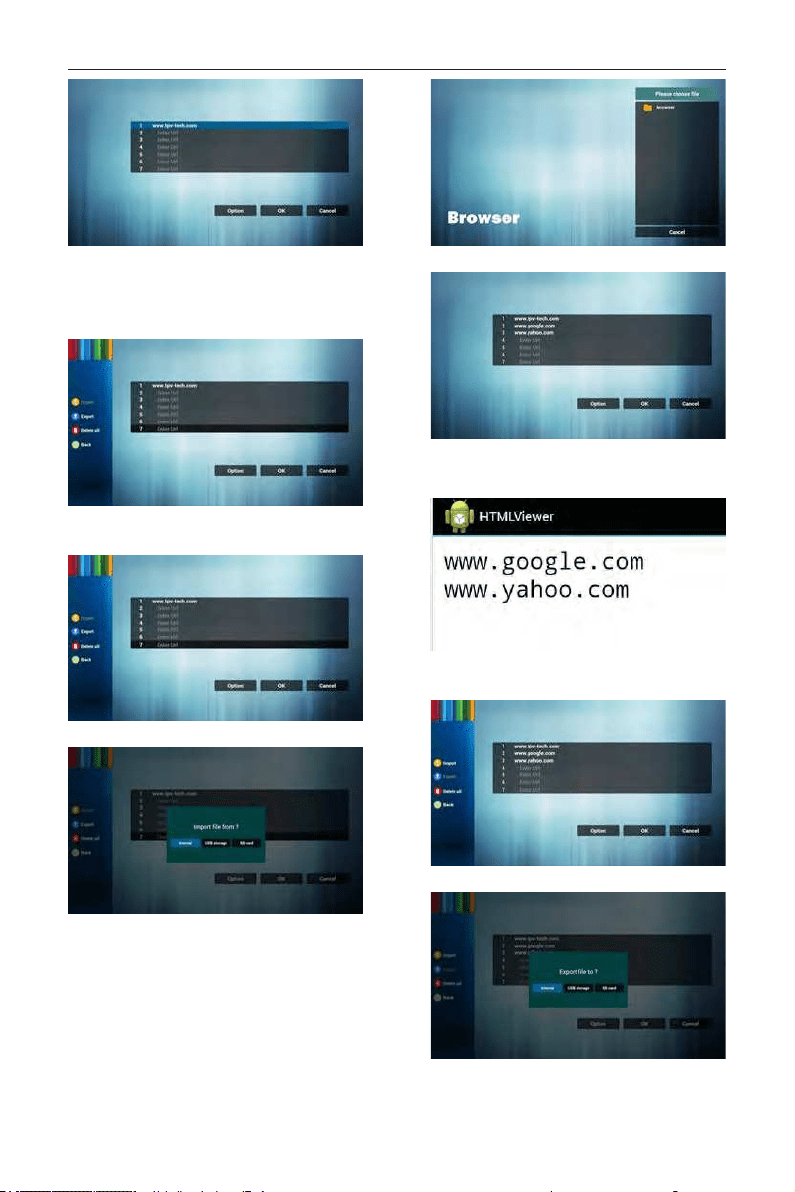
DS55MU01
16
4. Press “Option” then left side will pop up a list
Import : Import url list le
Export : Export url list le
Delete all : Delete all url record on right side
Back : left side list will be closed.
4.1 Import
• Click import
• Choose storage
• Choose le contains urls
• Import le and url will show on list
• File format for import
Format should be like below with le extension
“txt”
4.2 Export:
• Click export
• Choose storage
DS55MU01
17
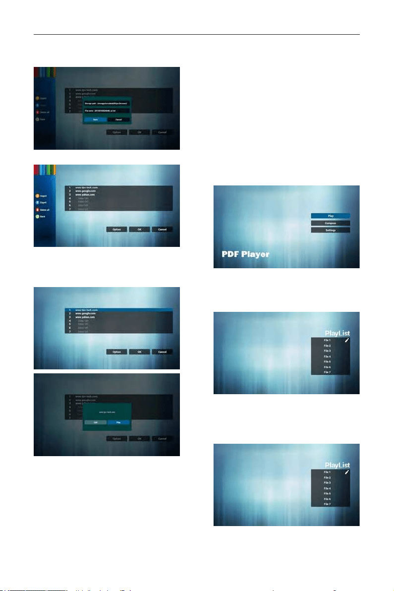
• Dialog shows path le will be saved and le’s
name.
Press “save” button then urls on list will be saved.
5. Press OK then url records will be saved
6. On url list page, if you select non-empty item, it
will show a dialog to ask edit or play url. If press
“Edit”, it will show edit url dialog, if press “Play”, it
will show web page of item’s url.
7. OSD menu interaction with Browser
7.1 Boot on source
• Set OSD menu => Conuration1 => Boot on
source => Input be BROWER Play List be 0.
Then PD will show Browser after reboot.
• Set OSD menu => Conuration1 => Boot on
source => Input be BROWER Play List be 1.
Then PD will show web page with 1st Url in
Browser app.
7.2 Schedule
Set OSD menu => Advanced option => Schedule
=>
On time1, Off time2, Input be BROWSER, any day
you want of week, and Play List.
Finally check the right box.
Then PD will show web page with Url in
Browser app at time1 and nish at time2.
4.6. PDF reader play
1. Home page of Pdf app, this page has three items:
“Play”, “Compose” and “Settings”.
Play : select playlist to play.
Compose: edit playlist.
Settings: setting play properties.
2. Select “Play” on home page, rst you should
choose one playlist to play between FILE 1 and
FILE 7.
The pencil icon means the playlist is non-empty.
3. Select “Compose” on home page, rst you should
choose one playlist to edit between FILE 1 and
FILE 7.
The pencil icon means the playlist is non-empty.
4. If an empty playlist is chosen, the app will guide
you to select the media source.
DS55MU01
18
All media les should be placed in /signage/ of
root directory. For example,
- pdfs in /root/signage/pdf/
5. You could edit or delete a non-empty playlist, just
choose the desired playlist which is with pencil
icon.
6. Once you start to edit a playlist, you will see
below screen.
Source - les in storage.
Playlist – les in playlist.
There are 4 icons which map to the keys of
remote controller. Option key – launch slide bar
Play key – play media le.
Info key – show media info.
Ok key – select/unselect le.
6-1. In the slide bar, it helps you to do the
following:
- select all : select all storage les.
- delete all : delete all playlist les.
- add/remove : update playlist from source.
- sort : sort playlist.
- save/abort : save or abort playlist.
- back : return.
7. If you choose “Sort” in the slidebar, you can
change the order of les one by one.
8. Select “Settings” on home page, this page has
two parts, “Repeat Mode” and “Effect Duration”.
Repeat Mode : play mode.
Effect Duration : photo effect duration.
Media Hotkey:
Play : Playback le.
Pause: Pause page.
Fast forward: go to next page, if the page is end
of the le, it will go to next le.
Rewind: back to last page, if the page is rst of
the le, it will back to last le.
Stop: return to rst page of le
Color Hotkey:
Blue : Zoom in.(+10%)
Yellow : Zoom out.(-10%)
OK : Restore zoom
Arrow keys:
Up/Down/Left/Right : Adjust page. (When the
page has zoomed in/out)
Left : Previous Page. (When the page has not
zoomed in/out)
Right : Next Page. (When the page has not
zoomed in/out)
Combination key:
Number key + OK key : select specic page,
and press ok key to change page.
- Press number key.
- Press OK key, the bottom of the page will
show the page number, if
page number over
DS55MU01
19
total page number, it will not change page and
show current page number at the bottom of the
page.
4.7. CMS
1) Server
Setup CMS server address
2) Account
Setup CMS account
3) PIN Code
Setup CMS PIN code
(4) Version
Ver.3
(5) Content
There are internal storage/SD card/USB storage
3 options for selecting.
When Ver.3, Server/Account/PIN code is available.
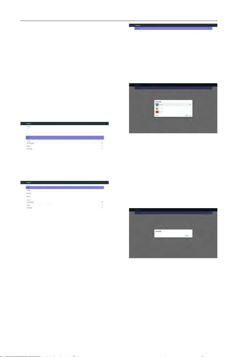
4.8. Custom App
User can set up the application for Customer Source
Note:
(1) Only display User Installed app.
(2) Will not show up system pre-install app.
4.8.1. OSD Menu operation:
RCU: Source -> Custom
If set up customer APK, PD will open customer app
when switch source to Customer mode.
If no set up customer APK, PD will show Black screen
when switch source to Customer mode.
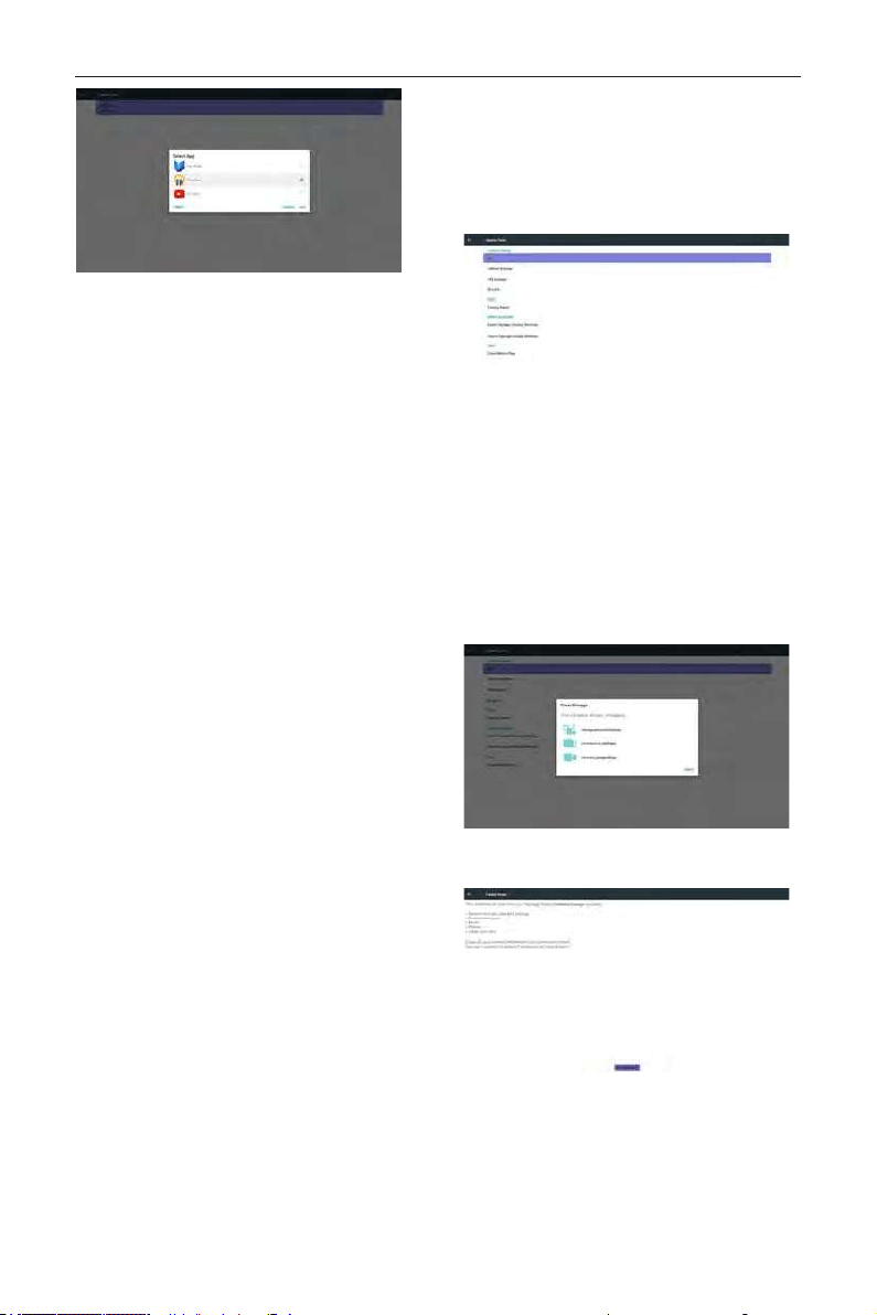
4.8.2. Function Introduction
Save
Select the App, click the Save will perform the
function of storage.
Forget
After press the Forget, can remove previously stored
information.
Cancel
Don’t do any change, directly closed Windows.
If no customer installed apk, the list will be blank.
The list will be blank and “Save””Forget” will be gray
and useless.
If customer installed apk,user can select customer
installed apk in list
• Case 1: Not set up Custom App case.
Customer app will show up and focus on rst
item automatically.
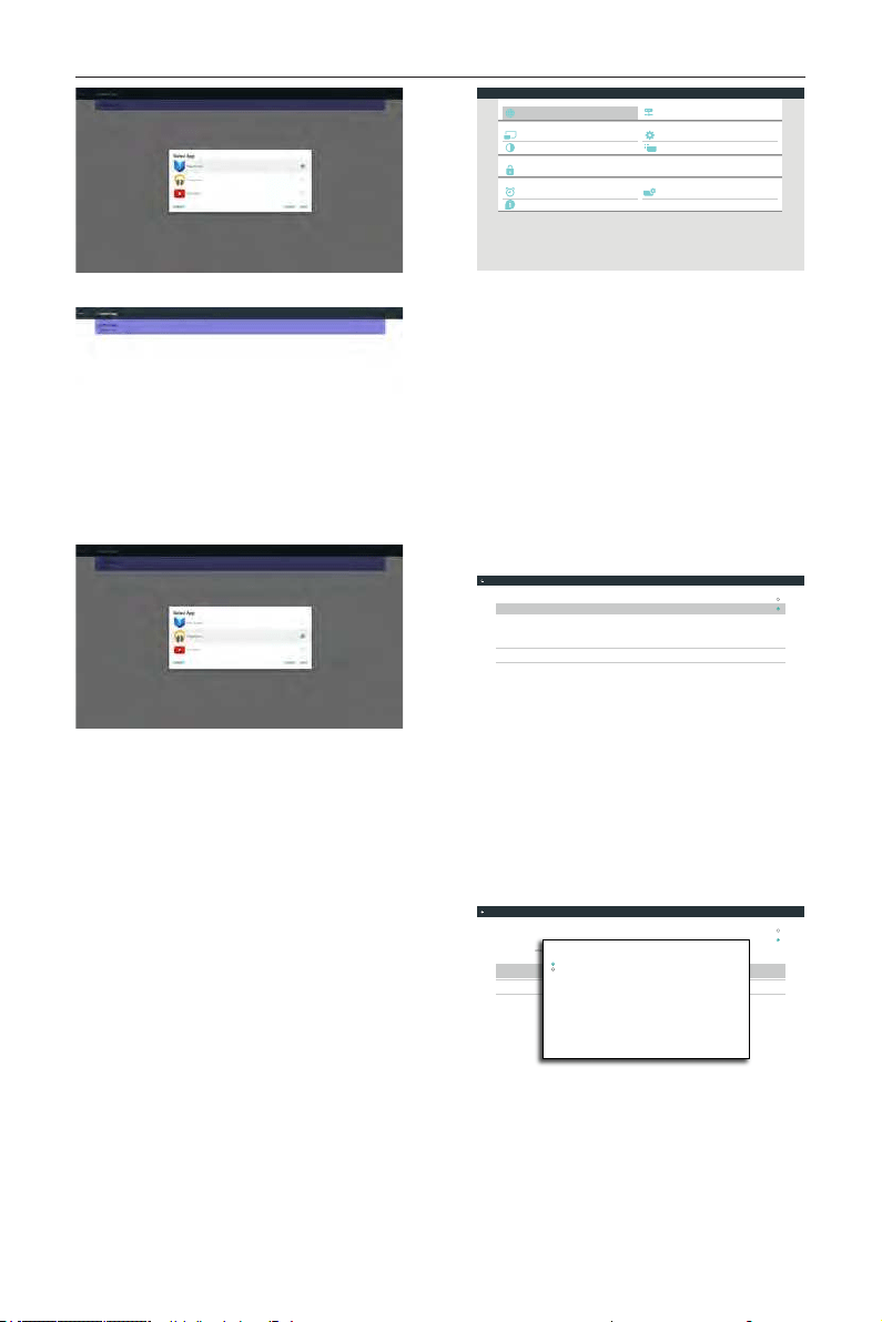
DS55MU01
20
After set up, the setting screen display the app name.
• Case 2: Set up Custom App case(there is entity
circle to the right of icon)
5. Signage display
5.1. Setting
Main items:
(1) Ethernet
(2) Proxy
(3) Signage Display
(4) System Tools
(5) Display
(6) Apps
(7) Security
(8) Date & time
(9) Developer options
(10) About
Developer options
System Tools
Proxy
Signage Display
Ethernet
Display
Apps
Security
Date & time
About
System
Personal
Device
Network
Settings
5.2. Ethernet
Enable/Disable to turn on/off Ethernet
After enable Ethernet, the settings will show:
(1) Connection Type (Available connection type:
DHCP/Static IP)
A. DHCP
B. Static IP
C. IP Address
D. Netmask
E. DNS Address
F. Gateway
(2) Mac Address
Connection Type
Static IP
Mac Address
00:24:67:21:57:ea
Ethernet Configuration
Main Switch
Disable
Enable
To see available networks, turn Ethernet on.
Ethernet
5.2.1. DHCP
DHCP mode:
(1) Cannot modify IP Address, Netmask, DNS
Address and Gateway.
(2) If connect successfully, it will display current
network conguration.
Connection Type
DHCP
Mac Address
00:24:67:21:57:ea
Ethernet Configuration
Main Switch
Disable
Enable
To see available networks, turn Ethernet on.
Ethernet
Ethernet Configuration
DISCARD SAVE
Connection Type
DHCP
Static IP
IP Address
172.17.2.12
Netmask
255.255.255.0
DNS Address
172.16.0.178
Gateway
172.17.2.254
5.2.2. Static IP
In Static IP mode, user can input IP Address, Netmask,
DNS address and Gateway
Note:
DS55MU01
21
IP address, netmask, DNS address and gateway address
input limitation
(1)Format:
I. number 0-9
II. decimal point “.”
Connection Type
Static IP
Mac Address
00:24:67:21:57:ea
Ethernet Configuration
Main Switch
Disable
Enable
To see available networks, turn Ethernet on.
Ethernet
Ethernet Configuration
DISCARD SAVE
Connection Type
DHCP
Static IP
IP Address
Netmask
DNS Address
Gateway
5.3. Proxy
Browser connect to Proxy server and ask Proxy server
to connect some website on Internet.
Enable/Disable to turn on/off Proxy server.
• Click “Enable” to switch proxy function “ON”
• Input the “Proxy hostname”. (Proxy server IP
address)
• Input the “Proxy port”. (Proxy server port
number)
• Select an “Type”. (Proxy server type.)
• Done.
- If the proxy server is need an authentication
to connect, please “check on” the
Authentication and input Username &
Password.
- If the proxy server is not need an
authentication to connect.
Proxy hostname
Proxy port
Type
HTTP
Proxy settings
Authentication
Username
Password
Authentication
Main Switch
Disable
Enable
Proxy
Note:
• Proxy type in HTTP, HTTPS, SOCKS4,
SOCKS5 are support.
• Only support the connection through the
proxy server with TCP port 80 & 443 &
5228.
• Proxy server with authentication on
Windows Sever Series is not support.
5.4. Signage Display
Divide into 4 groups: General Settings / Server Settings
/ Source Settings / Security
(1) General Settings
A. Signage Display Name
B. Boot Logo
C . Screenshot
(2) Server Settings
A. Email Notication
B. FTP
C . Remote Control
D. SICP Network Port
(3) Source Settings
A. Media Player
B. Browser
C . CMND & Play
D. PDF Player
E. Custom app
(4) Security
A. External Storage
(5) Other
A. TeamViewer Support
B. Platform Web API
Email Notification
FTP
Remote Control
SCIP Network Port
Server settings
Media Player
Browser
CMND & Play
PDF Player
Custom App
Source settings
General settings
Signage Display Name
PD_0024672157ea
Security
External Storage
SD card/USB External Storage Unlock
Boot Logo
Screenshot
Signage Display
5.4.1. General Settings
1. Signage Display Name
Set up PD name “PD_” + Ethernet Mac Address.
Note:
Input limitation:
(1) length: Max 36 characters
(2) format: no limit
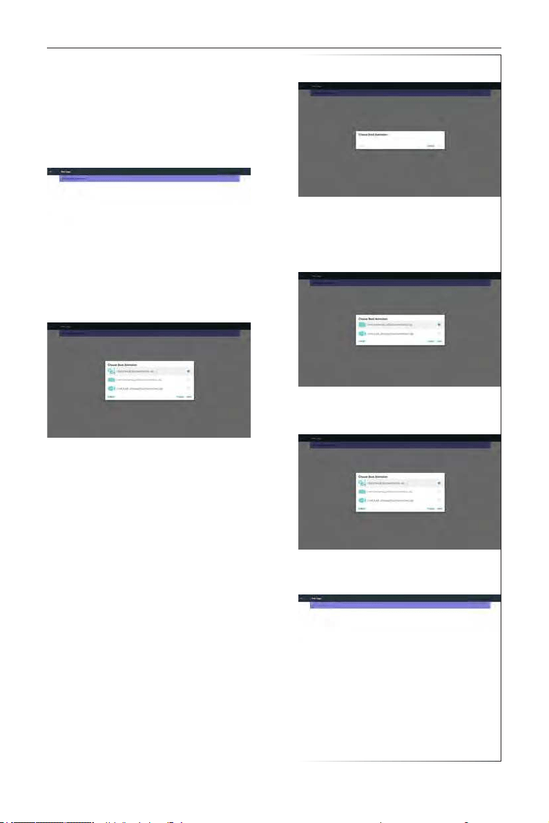
2. Boot Logo
1) Scalar OSD menu to control Android boot logo
enable/disable
Scalar OSD menu operation
DS55MU01
22
RCU: Home -> Conguration2 -> Logo -> On/
Off/User
In user mode, user can choose their own boot
logo animation le.
Note:
(1) Boot animation le name: bootanimation.zip
(2) Will pop-up a window for user to select USB
and SD card. No priority issue.
2) When boot logo selected, PD will check if
there is bootanimation.zip under USB and SD
card.
Function introduction:
a. Option description
/data/local
Use customized boot animation le which is
copied from SD card or USB
/mnt/external_sd
Use boot animations le under SD card
/mnt/usb_storage
Use boot animations le under USB
b. Save
Press save key to save SD card or USB
bootanimation.zip to /data/local and set it as
boot logo.
c. Forget
Press Forget key to delete /data/local
bootanimation.zip and not show boot logo.
d. Cancel
Close dialogue w/o changes.
Scenario introduction:
Case 1
The user don’t settle customized boot logo. PD
does not nd any bootanimation.zip le under
SD and USB. The list will be blank. Save and
Forget button will be gray and useless.
Case 2
The users do not settle customized boot logo.
PD nd bootanimation.zip le under SD and
USB. The screen will show bootanimation.zip and
select the rst le automatically.
Case 3
The user settle customized boot logo, the screen
will show /data/local/bootanimation.zip.
3) If OSD menu Logo item is On or Off, the
users cannot choose boot animation in Android
settings.
3. Screenshot
Via Enable/Disable to control screenshot On/Off.
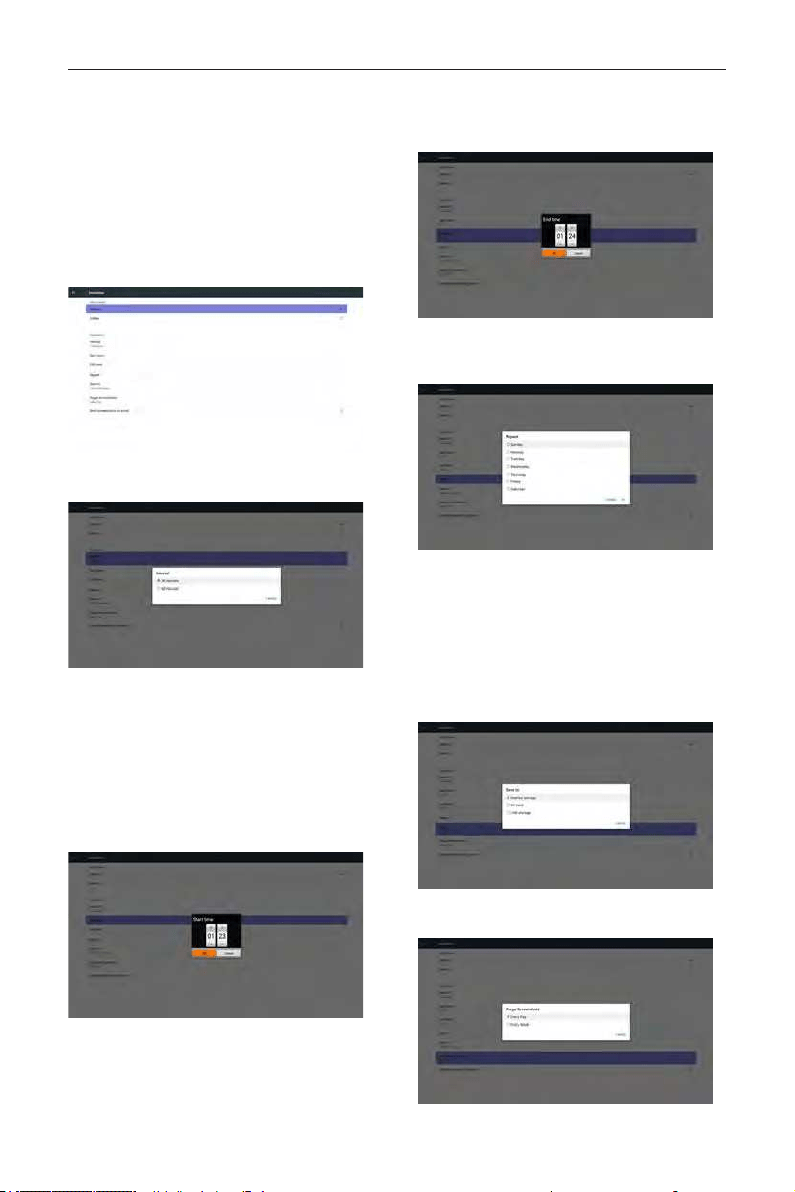
DS55MU01
23
After Enable, user can set screenshot timeslot and save
path.
Note:
Time slot of deletion and screenshot:
(1) Will delete picture at initial time 0 sec.
(2) Will screeshot at rst 40 sec.
(3) Media player, Browser, CMND & play, PDF reader,
Custom source are supported.
(4) Screenshot will not include video container
1) Interval
Set up interval timeframe. 30 mins or 60 mins.
2) Start Time
Set up screenshot start time.
Note:
(1) If no start time, the screen will show current
time automatically
(2) Just press Back key to exit dialog for Set up
(3) Start time cannot be newer than End time. It
will show Error toast.
3) End Time
Set up screenshot End time
Note:
(1) If no End time, the screen will show current time
automatically
(2) Start time cannot be newer than End time. It will
show error toast.
4)Repeat
Set screenshot repeat cycle. User can choose
screenshot time frame. (Multiple selection)
5)Save to
Set up screenshot save path. Internal storage, SD
card or USB storage.)
Note:
picture storage path
(1) In root of internal storage/usb storage/sd card,
PD will create folder automatically.
(2) The picture will save to OTS/Screenshot/.
6)Purge Screenshots
Set up purge timeframe. One day or One week.
DS55MU01
24
(7) Send screenshots via email
After check this item, it will send screenshot to
email of administrator
Please refer to 6.2.1 Email notication
Note:
Please conrm Email setting is done.
5.4.2. Server Settings
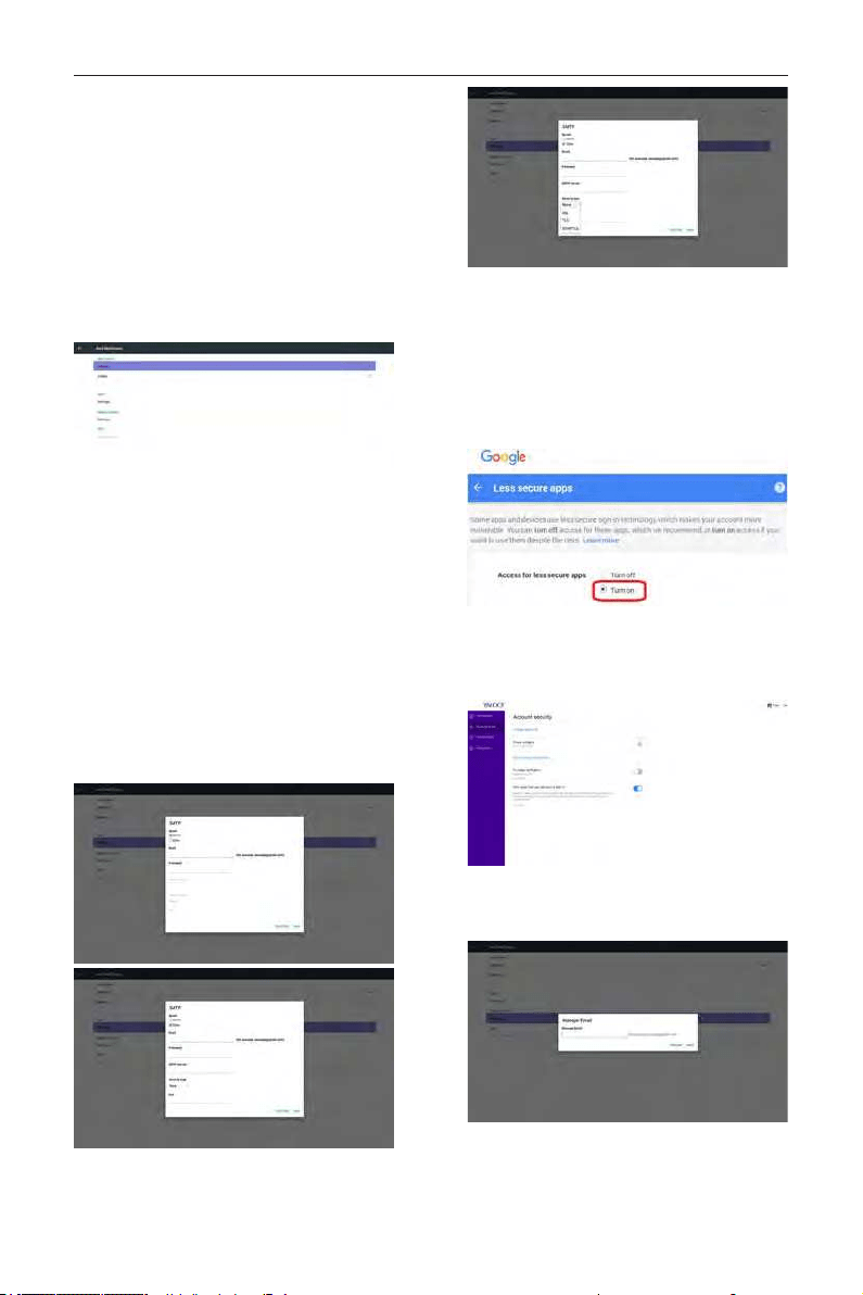
1. Email Notication
Via Enable/Disable to control Email On/Off)
After Enable, user can set up Email notication
conguration.
1) SMTP
Set SMTP conguration)
User can set Gmail account or other mail
account.
User can select other mail account and set up
SMTP server, Security type and port item
Note
Password input limitation
(1) Length: 6-20 characters
(2) Format: no limit
(3) unavailable port: 5000
Gmail safety setting
If Gmail is not working when setting is complete,
please test Gmail account via PC and link below
URL
https://www.google.com/settings/security/
lesssecureapps
And conrm “Access for less secure apps” item is
Turn On
Yahoo Email Security Setting
If Yahoo Email is not working when setting
complete, please conrm “Allow apps that use
less secure sign in” item is enabled.
2)Manager Email
Email
Set up Receiver mail account
3)Test
Send Test Mail
To test Gmail account receive/send function.
DS55MU01
25
Note
(1) When Email is Disable, “Send Test Mail Button”
button will gray out
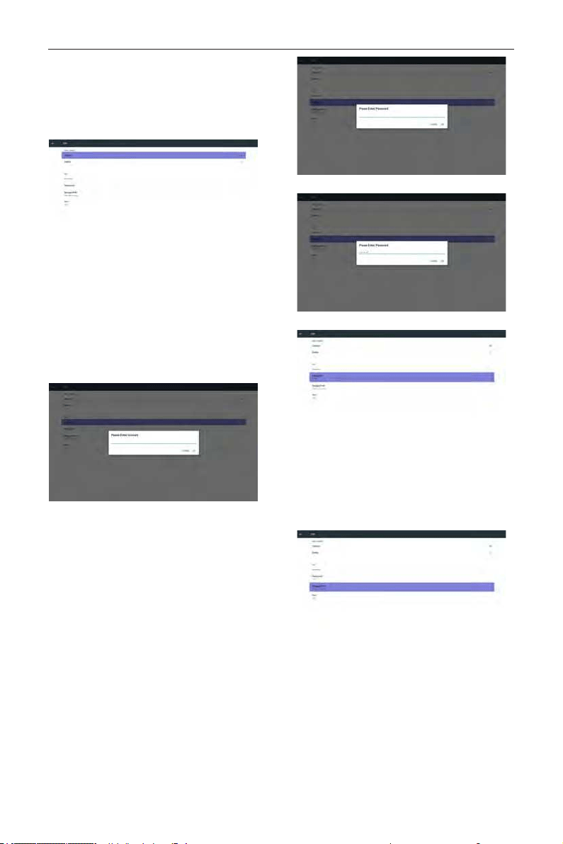
2. FTP
Via Enable/Disable to control FTP On/Off. After set up,
PD can share FTP les.
1) Account
Set up FTP account
Note:
Input limitation
(1) Length: 4-20 characters
(2) Format:
I. English a-z and A-Z
II. Number 0-9
2) Password
Set up FTP password.
Note:
Input limitation
(1) Length: 6-20 characters
(2) Format:
I. English a-z and A-Z
II. Number 0-9
FTP password display
(1) Will show “*” symbol to instead password if set up
password via remote control.
(2) After set up, the password text will show as “*”
symbol.
Before password input:
After password input:
Set up completed screen:
3)Storage Path
Show default path: Internal storage
Note:
Can only display Internal storage, cannot be
modied.(Only show path)
4) Will show Server is unbinded if Remote control
server feedback unbinded status.
5) Port
Set up FTP port number. Default: 2121
Note:
Input limitation
(1) Length: Max 5 characters
(2) Range: 1024 ~ 65535
DS55MU01
26
(3) Format: Number 0-9
(4) Unavailable port: 5000
(5) The port number must more than 1024
3. Remote Control
Via Enable/Disable to Control Remote Control On/
Off
User can input Server address. If server does not
registered, it will ask user for PIN code.
Bind status:
(1) Will show network is disconnected if not yet
connects to network.
(2) Will show Server is disconnected if
network connected but remote control server
disconnected.
(3) Will show Server is unbinded if Remote
control server feedback unbinded status.
(4) Will show Server is binded if Sever binded
successfully.
(5)Will show Error PIN code if input incorrect
PIN code.
4. SICP Network Port
Change SICP Network Port.
Note:
1. Range: 1025-65535
2. unavailable port: 8000 / 9988 / 15220 / 28123 /
28124
DS55MU01
27
5.4.3. Source Settings
1. Media Player
Can Edit Media Player play list and effect settings.
(1) Open Media Player Player List edit page.
(2) Open Media Player slideshow effect edit page.
2. Browser
Can edit Bookmark conguration.
(1) Open Browser setting page.
3. CMS
1) Server
Setup CMS server address
2) Account
Setup CMS account
3) PIN Code
Setup CMS PIN code
(4) Version
Ver.3
(5) Content
There are internal storage/SD card/USB storage 3
options for selecting
When Ver.3, Server/Account/PIN code is available.
4. PDF Player
Can edit PDF Player Play List and Effect Settings.
DS55MU01
28
(1) Open PDF Player Player List edit page.
(2)
Open PDF Player effect edit page
.
5. Custom App
User can set up the application for Customer Source.
Note
(1) Only display User Installed app.
(2) Will not show up system pre-install app.
Scalar OSD menu operation
RCU: Source -> Custom
If set up customer APK, PD will open customer app
when switch source to Customer mode.
If no set up customer APK, PD will show Black screen
when switch source to Customer mode.
Function introduction
(1) Save
Select App and press Save key to save it.
(2) Forget
Press Forget key to clean previous stored data
(3) Cancel
No change, close window directly
If no customer installed apk, the list will be blank.
No option for choose. Save and Forget key will be
gray and unavailable.
User can select customer installed apk in list
No setup Custom App
Screen will show available apps and focus on rst app
item automatically.
After setup, it will show App name
Case2. Setup Custom App. (there is a checked circle
on right)external storage.
DS55MU01
29
5.4.4. Security
1. External Storage
Enable: SD card/USB External Storage Lock.
Disable: SD card/USB External Storage Unlock.
Note:
Must re-plug SD card/USB External Storage after
unlock the external storage.
5.4.5. Other
(1) TeamViewer Support
Enable / Disable TeamViewer support.
(2) Platform Web API
Enable / Disable Platform Web API.
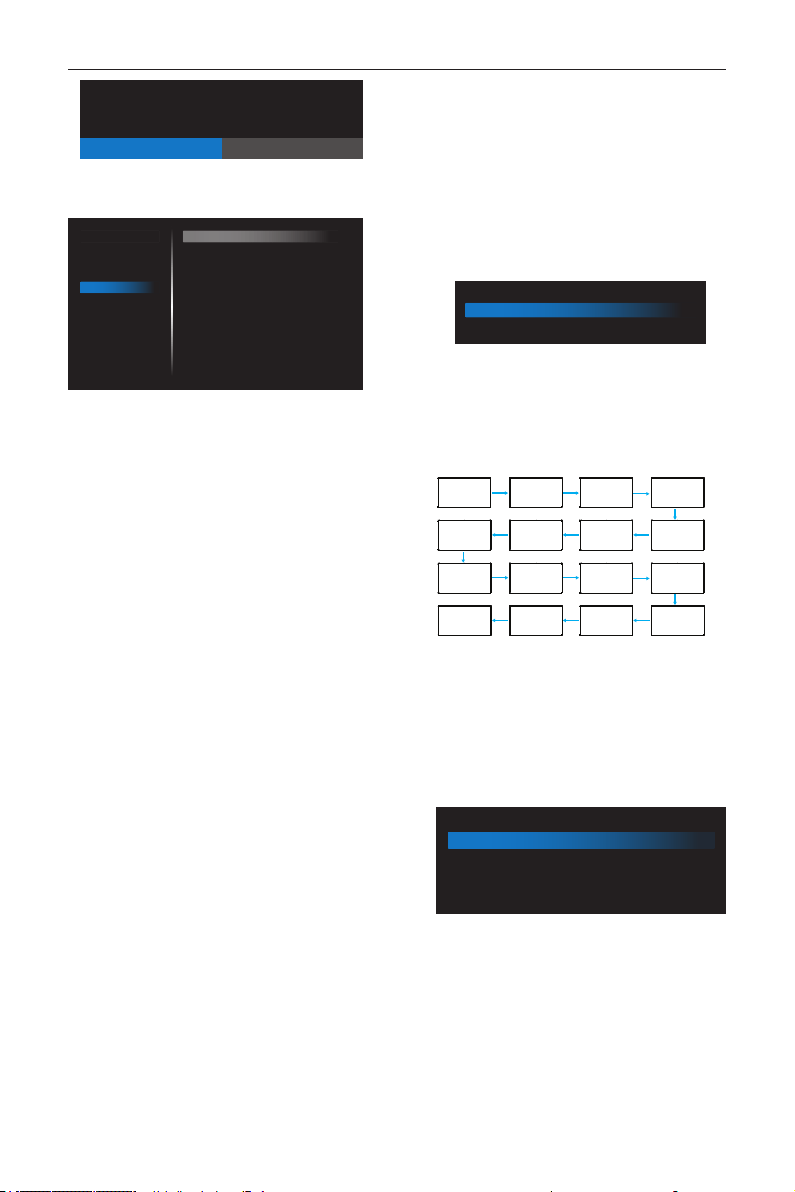
5.5. System Tools
System tools 4 main functions:
(1) Clear Storage
(2) Factor y Reset
(3) Impor t & Expor t
(4) Clone Media Files
5.5.1. Clear Storage
The purpose is to clear all data in OTS folders.
Divided into 4 mode:
(1) Clear all OTS folders
(2) Only clear OTS folder under Internal storage.
(3) Only clear OTS folder under USB storage.
(4) Only clear OTS folder under SD card.
Pop-up the window to display all folders which can be
clear.
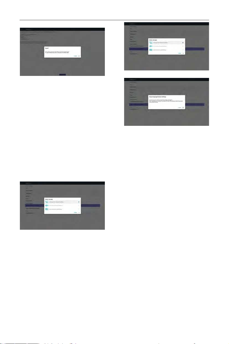
5.5.2. Factory Reset
Factory Reset can recover to Factory default settings.
DS55MU01
30
Press OK to execute Reset function automatically
.
5.5.3. Import & Export
The function of Import & Export PD settins.
Notes.
(1) Settings.db (Saved le name: settings.db)
(2) Will save to OTS folder in storage
5.5.3.1 Export Signage Display
Settings
Will export to OTS folder under USB or SD card
(1) Export settings.db. Include OSD setting,
Android settings but “Signage Display Name”
and “Boot Logo”
(2) Export 3
rd
party apk to OTS/app/
Note:
If no OTS folder exists in USB or SD card, it will be
created automatically.
List all available storage (internal/SD/USB)
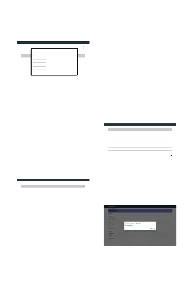
5.5.3.2 Import Signage Display
Settings
Import settings.db from OTS folder under USB or
SD card.
(1) Import settings.db. Include OSD setting,
Android settings but “Signage Display Name”
and “Boot Logo”
(2) Auto install 3
rd
party apk from OTS/app/
List all available storage (Internal/SD/USB)
Show notication dialog before database import
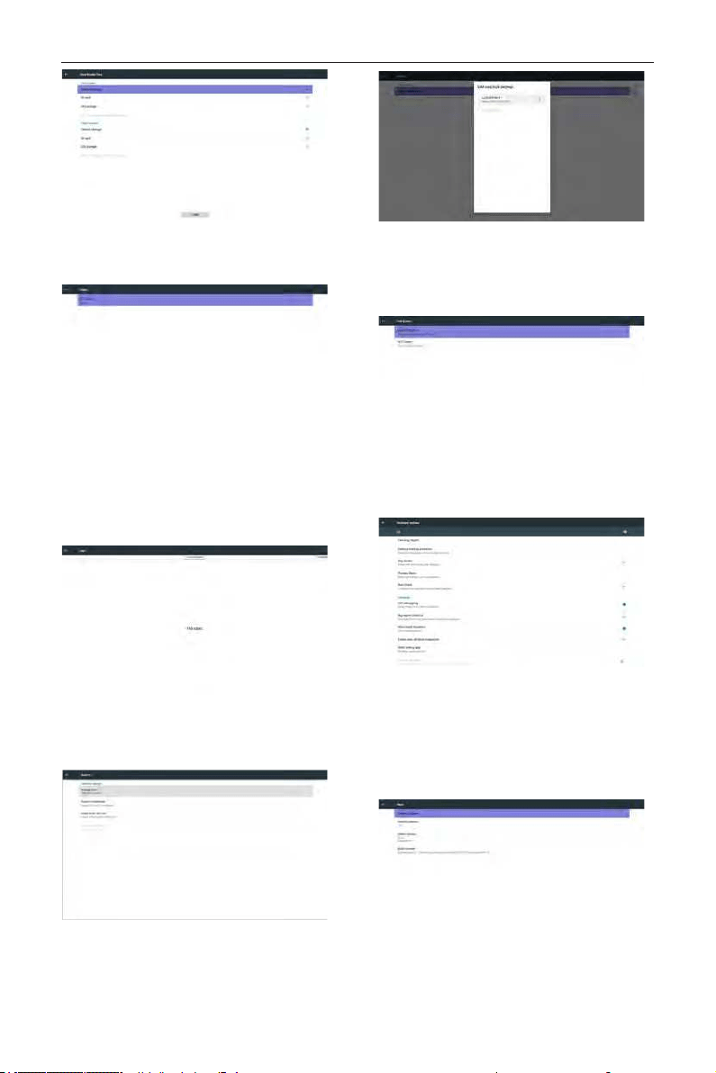
5.6. Clone Media File
Clone media le from Internal, SD or USB OTS
folder.
1. The cloned folder name under OTS folder
(1) OTS/photo
(2) OTS/music
(3) OTS/video
(4) OTS/cms
(5) OTS/pdf
(6) OTS/browser
2. The cloned le extension name is “.cms”)
Clone Source
(1) Internal storage
(a) check FTP
(b) check /OTS/
(2) SD / USB
Files under root
Target Location
(1) Internal storage
Save to /OTS/
(2) SD / USB
Save to root
DS55MU01
31
5.7. Display
User can modify the font size, can choose: Small/
Normal/Large/Huge
5.8. Apps
Display applications information.
Note
(1) User options key on RCU to show setting
option.
5.9. Security
(1) Credential storage
Control panel of certicates
5.10. Date & time
Via Scalar OSD menu to control Auto Time On/Off.
Note:
Add new NTP server to display current server IP
.
5.11. Developer options
Android developer options.
5.12. About
Main info in About:
(1) System updates
(2) Android version
(3) Kernel version
(4) Build number
DS55MU01
32
5.12.1. System updates
Will automatically search update.zip in USB.
Will be shown in list for user selection if found
Note:
(1) Only support Android Full image.
(2) le name should be update.zip.
(3) the le should be located in root of storage.
After select update.zip le, PD will restart and start
to update.
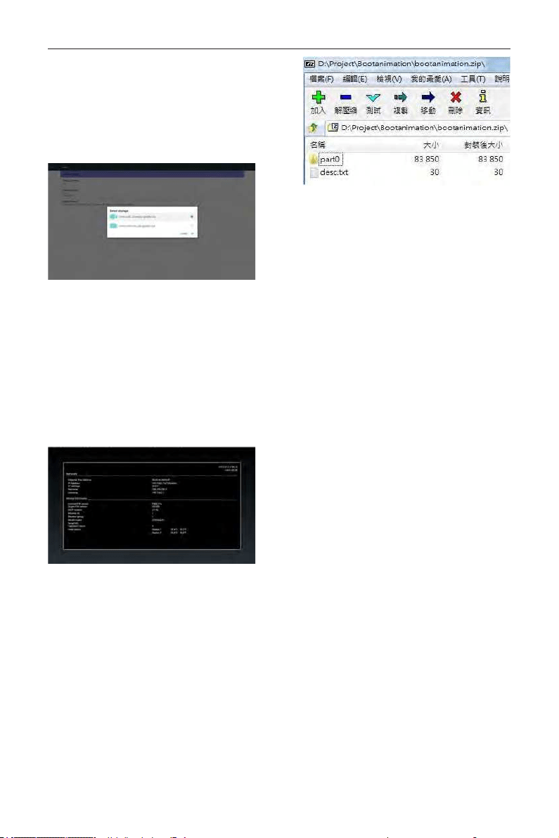
5.13. Supplementary
5.13.1. Quick Info
You can press “Info + 77” to startup quick info.
Quick info will show “Network” and “Monitor
Information”, as below:
Note:
Operation hours : It is updated every minute.
Heat status : It is updated every 5 seconds.
5.13.2. How to custom an Android boot
animation?
1. Overview
The Android boot animation is used script to
load PNG les when the device boots. It is
contained within an uncompressed zip le called
bootanimation.zip.
2. Inside the bootanimation.zip le
The bootanimation.zip as follow:
• The image folder (Contains PNG images named
in incremental numbers)
• The desc.txt le
(1) The image folder
These contain PNG images named in numbers,
starting from something like 0000.png or 0001.
png and proceeding with increments of 1. There
has to be at least one folder and there is no
known upper limit to the number of folders.
(2) The desc.txt le
This le denes how the images in the folder(s)
are displayed during the boot animation, in the
following format:
- Width Height Frame-rate
- mode Loop delay-time Folder1
- mode Loop delay-time Folder2
An example of a desc.txt le is:
- 1920 1080 30
- p 1 0 part0
- p 0 0 part1
a. The rst line
1920 and 1080 dene the width and height of
the screen resolution.
30 is the frame rate in fps (frames per
second) i.e. number of images to display per
second.
b. The second and third lines have a same
format.
The rst ‘p’ denes play mode is immediately
stop playing when boot complete.
The number after ‘p’ denes repeat mode
- specifying 0 would make the part loop
indenitely till the device has boot
complete.
- specifying 1 would make the part
playback once.
The next number denes the delay time(ms).
For example, if set 10, when all image les has
been playback, system will delay 10ms.
The part0 and part1 are image folder name.
The above example, the boot animation will play at
a resolution of 1920 by 1080 pixels, at a frame rate
DS55MU01
33
of 30 fps, starting with the contents of part0 folder and
after playing them in one loop, switching to contents
of part1 folder and playing them continuously till the
device boot complete.
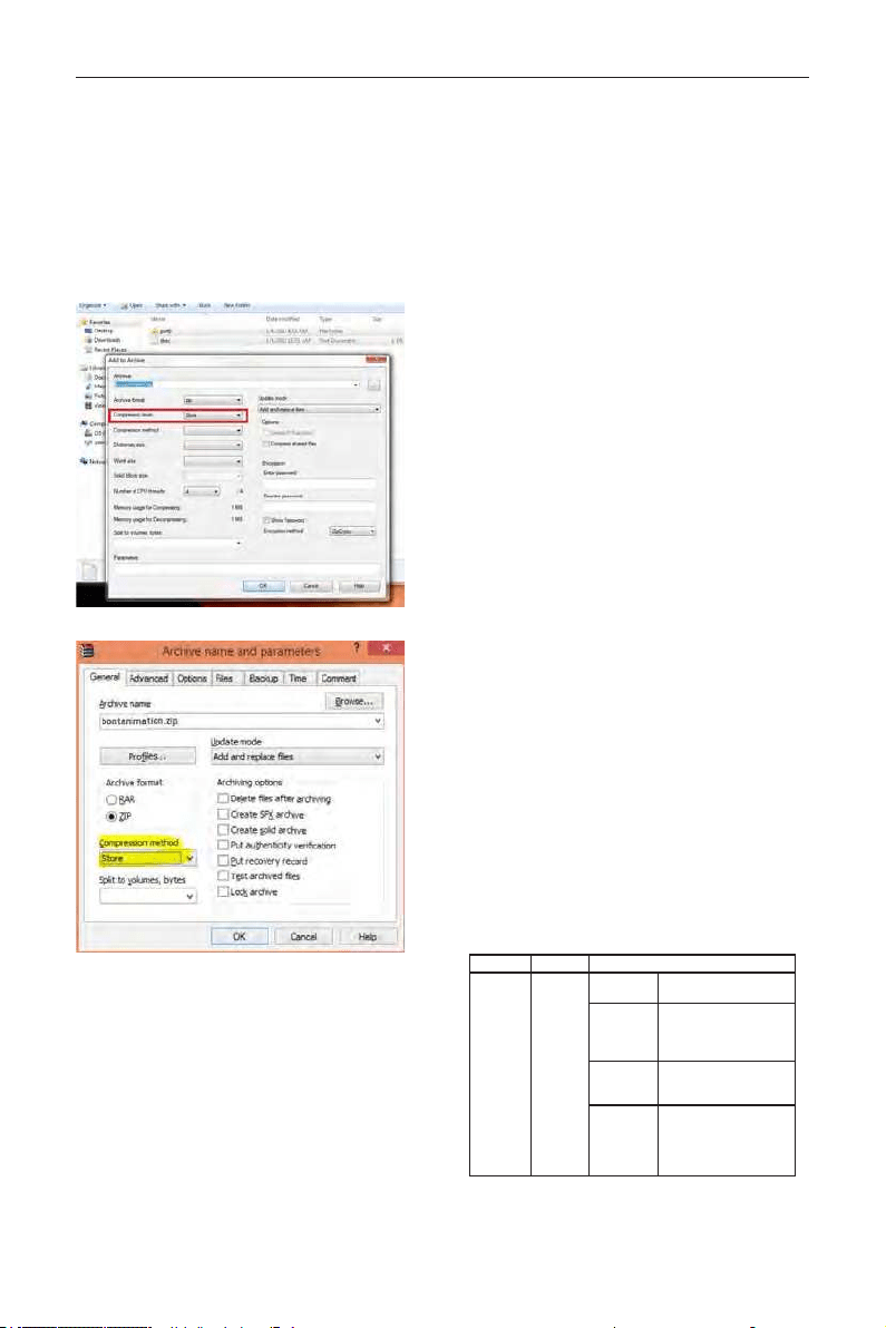
3. Zip le:
Select everything (image folders and desc.txt)
inside the Bootanimation folder and zip them into a
new uncompressed zip archive using your favorite
compression utility like 7zip or WinRAR and so on.
If using 7zip, set compression level to “Store”
If using WinRAR, set “Compression method” to “Store”
or else bootanimation WON’T work
4. Apply the custom bootanimation
Procedure:
(1). Put your custom bootanimztion.zip le into
external SD card or USB and plug into PD
platform.
(2.) Make sure the Logo option is enabled.
Press Home key on RCU: OSD menu ->
Conguration 2 -> Logo -> set “User”
(3.) Press combination key “Home + 1888” on
RCU to go to Admin mode:
Settings -> Signage Display -> GENERAL
SETTINGS -> Boot Logo
(4). The system will nd the bootanimation.zip in
external SD card or USB automatically and copy it
to /data/local
(5.) Once step 1~4 has been done, restart the
system. The new customized boot animation should
be displayed during boot time.
5.13.3. How to Install Android app?
There are 3 ways to install your own android app.
(a) Via File Manager in Admin Mode
1. If you have apk already
1.1 copy your apk to USB disk or SD card,
and then plug them into OTS Android Signage
Display.
1.2 Go to Admin Mode > Apps > File Manager
1.3 Using File Manager and nd out your apk
and then you can install. Just press “ok” on the
selected apk.
2. Download apk by Chromium browser, and then
go to <internal storage path>/Download/ by File
Manager.
2.1 The rest of steps is the same as above.
Please note, each model may have different
<internal storage path>.
(b) Via Adb Shell
1. Make sure that your PC can connect to OTS
Android Signage Display using adb.
2. Prepare your apk in a folder(for example, C:\
apkfolder) on PC.
3. Execute the following instruction by command
line tool.
C:\apkfolder> adb install -r apk_name.apk
(c) Via Customized Intent
1. If you develop an apk which can download any
android app, then your apk can issue a customized
intent.
2. Giving the apk name and the path it was stored.
The system will help you to install by program.
Description Intent Parameters
Sw Update
php.intent.
action.
UPDATE_
APK
lePath
The absolute le path
including the le name.
Keep
Indicate that you want to
keep the le or not after
updating. The default value is
false.
packageName
The target package you want
to launch automatically after
updating.
activityName
The target activity you want
to launch automatically after
updating. But if current top
activity is not activityName,
nothing happened.
For example,
DS55MU01
34
Intent intent = new Intent();
intent.setAction(“php.intent.action.UPDATE_APK”);
intent.putExtra(“lePath”, “/sdcard/Download/apk_
name.apk”);
intent.putExtra(“keep”, true);
intent.putExtra(“packageName”, “com.example.apk_
name”);
intent.putExtra(“activityName”, “com.example.apk_
name.MainActivity”);
sendBroadcast(intent);
6. OSD Menu
An overall view of the On-Screen Display (OSD)
structure is shown below. You can use it as a
reference for further adjusting your display.
6.1. Navigating the OSD Menu
6.1.1. Navigating the OSD menu using the
remote control
FORMAT
SOURCE
INFOLIST
OPTIONSADJUST
1. Press
[
]
button on the remote control to
display the OSD menu.
2. Press
[
]
or
[ ]
button to choose the item you
want to adjust.
3. Press [OK] or
[
]
button to enter the
submenu.
4. In the submenu, press
[
]
or
[ ]
button to
toggle among items, press
[
]
or
[
]
button
to adjust settings. If there is a submenu, press [OK]
or
[
]
button to enter the submenu.
5. Press
[
]
button to return to the previous
menu, or press
[
]
button to exit the OSD
menu.
6.1.2. Navigating the OSD menu using the
display’s control buttons
1. Press [MENU] button to display the OSD menu.
2. Press [
] or [ ] button to choose the item
you want to adjust.
3. Press [
] button to enter the submenu.
4. In the submenu, press [
] or [ ] button to
toggle among items, press [
] or [ ] button to
adjust settings. If there is a submenu, press [
]
button to enter the submenu.
5. Press [MENU] button to return to the previous
menu, or press [MENU] button several times to
exit the OSD menu.

DS55MU01
35
6.2. OSD Menu Overview
6.2.1. Picture menu
Picture
Screen
Audio
Configuration 1
Configuration 2
Advanced option
Brightness
Contrast
Sharpness
Black level
Tint
Color
Noise reduction
Gamma selection
Color temperature
Color control
Smart power
Overscan
90
50
20
50
50
55
Medium
Native
Native
Action
Off
Off
Brightness(Picture)
Adjust the overall image and background screen
brightness(backlight).
Contrast
Adjust the image contrast ratio for the input signal.
Sharpness
This function is digitally capable to keep crisp image at
any timings.
It is adjustable to get a distinct image or a soft one
as you prefer and set independently for each picture
mode.
Black level
Adjust the image brightness for the background.
NOTE: sRGB picture mode is standard and cannot be
changed.
Tint (Hue)
Adjust the tint of the screen.
Press + button the esh tone color becomes greenish.
Press - button the esh tone color becomes purplish.
NOTE: VIDEO mode only.
Color(Saturation)
Adjust the color of the screen.
Press + button to increase color depth.
Press - button to decrease color depth.
NOTE: VIDEO mode only
Noise Reduction
Adjust the noise reduction level.
Gamma selection
Select a display gamma. It’s refer to the brightness
performance curve of signal input. Choose from
{Native} / {2.2} / {2.4} / {s gamma} / {D-image}.
NOTE: sRGB picture mode is standard and cannot be
changed.
Color temperature
It is used to adjust the color temperature.
The image becomes reddish as the color temperature
decreases, and becomes bluish as the color
temperature increases.
CCT 10000º K 9300 º K 7500 º K 6500 º K 5000 º K 4000 º K 3000 º K
X 0.279 ±
0.030
0.283 ±
0.030
0.299 ±
0.030
0.313 ±
0.030
0.346±
0.030
0.382±
0.030
0.440±
0.030
Y 0.292 ±
0.030
0.298 ±
0.030
0.315 ±
0.030
0.329 ±
0.030
0.359±
0.030
0.384±
0.030
0.403±
0.030
Color control
The color levels of red, green, and blue are adjusted by
the color bars.
R: Red gain, G: Green gain, B: Blue gain.
Smart power
Smart Power control is not relative to brightness
control:
1. Initial setting Brigthness
90 (in the range from 0-100)
Power consumption 90% of maximum power
consumption
2. Smart Power
OFF: no adaptation
MEDIUM: 80% of power consumption relative to
current settings
HIGH: 65% of power consumption relative to
current settings
Overscan
Change the display area of the image.
ON: Set to display area about 95%.
OFF: Set to display area about 100%.
Picture reset
Reset all settings in the Picture menu.
Select “Yes” and press “SET” button to restore to
factory preset data.
Press “EXIT” button to cancel and then return to the
previous menu.
6.2.2. Screen menu
Picture
Screen
Audio
Configuration 1
Configuration 2
Advanced option
H position
V position
Clock
Clock phase
Zoom mode
Custom zoom
Auto adjust
Screen reset
50
50
97
0
Full
Action
Action
Action
H position
Control Horizontal Image position within the display
area of the LCD.
Press + button to move screen to right.
DS55MU01
36
Press - button to move screen to left.
NOTE: VGA input only.
V position
Control Vertical Image position within the display area
of the LCD.
Press + button to move screen to up.
Press - button to move screen to down.
NOTE: VGA input only.
Clock
Press + button to expand the width of the image on
the screen the right.
Press - button to narrow the width of the image on
the screen the left.
NOTE: VGA input only.
Clock phase
Adjust the focal length of the monitor. It is used to
remove any horizontal interference and make the
text look clear.
NOTE: VGA input only.
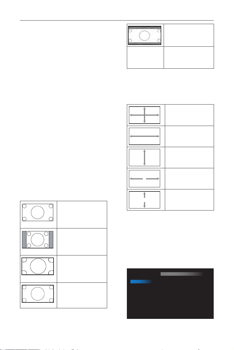
Zoom mode
HDMI, DP, VGA, OPS: {Full} / {4:3} / {Real} / {21:9}/
{Custom}.
Playing media in Media Player : {Full} / {4:3} / {Real} /
{21:9}
There are no function when BROWSER, CMND &
Play, PDF Player, PDF Player, Custom and Media Player
UI and Android UI
Zoom Mode will be “Full” when tiling
Full
This mode restores the
correct proportions of
pictures transmitted in 16:9
using the full screen display.
4:3
The picture is reproduced in
4:3 format and a black band
is displayed on either side of
the picture.
Real
This mode displays the image
pixel-by-pixel on screen
without scaling the original
image size.
16:9
The picture is reproduced in
16:9 format and a black band
at the top and bottom.
21:9
The picture is reproduced in
21:9 format and a black band
at the top and bottom.
Custom
Choose to apply the custom
zoom settings in the Custom
Zoom submenu.
Custom zoom
You can use this function to further customize the
zoom settings to suit the image you want to display.
NOTE: This item is functional only when the
{Zoom mode} is set to {Custom}.
Zoom
Expands the horizontal and
vertical sizes of the image
simultaneously.
H zoom
Expands the horizontal size
of the image only.
V zoom
Expands the vertical size of
the image only.
H position
Moves the horizontal
position of the image left or
right.
V position
Moves the vertical position
of the image up or down.
Auto adjust
Press “Set” to detect and adjust H position, V position,
Clock, Phase automatically.
NOTE: VGA input only.
Screen reset
Reset all settings in the Screen menu to factory
preset values.
6.2.3. Audio menu
Picture
Screen
Audio
Configuration 1
Configuration 2
Advanced option
Balance
Treble
Bass
Volume
Audio Out (Line Out)
Maximum Volume
Minimum Volume
Mute
Audio source
Audio reset
Audio Out Sync
50
50
50
30
30
100
0
Off
Digital
Action
Off

DS55MU01
37
Balance
Adjust to emphasize left or right audio output balance.
Treble
Adjust to increase or decrease higher-pitched sounds.
Bass
Adjust to increase or decrease lower-pitched sounds.
Volume
Adjust to increase or decrease the audio output level.
Audio out (line out)
Adjust to increase or decrease line out output level.
Maximum volume
Adjust your own limitation for the maximum volume
setting. This stops the volume from being playing at too
loud a level.
Minimum volume
Adjust your own limitation for the minimum volume
setting.
Mute
Turn the mute function on/off.
Audio source
Select the audio input source. There are no audio
output when no video signal.
Analog: audio from audio input
Digital : audio from HDMI audio.
Audio reset
Reset all settings in the Audio menu to factory preset
values.
Audio Out Sync
Enable/disable audio out (line out) volume adjustability
to sync with internal speakers.
6.2.4. Configuration1 menu
Picture
Screen
Audio
Configuration 1
Configuration 2
Advanced option
Switch on state
Panel saving
RS232 routing
Boot on source
WOL
RGB Range
Configuration1 reset
Factory reset
Force on
Action
RS232
Action
Off
Auto
Action
Action
Switch on state
Select the display status used for the next time you
connect the power cord.
• {Power off} - The display will remain off when the
power cord is connected to a wall outlet.
• {Forced on} - The display will turn on when the
power cord is connected to a wall outlet.
• {Last status} - The display will return to the
previous power status (on/off/standby) when
removing and replacing the power cord.
Panel saving
Choose to enable the panel saving functions and thus
reduce the risk of
“image persistence” or “ghost-imaging”.
• {Brightness} - Select {On} and the image
brightness will be reduced to an appropriate level.
The Brightness setting in the Picture menu will be
unavailable when selected.
• {Pixel shift} - Select the time interval ({Auto} / {10
~ 900} Seconds/ {Off}) for the display to slightly
expand the image size and shift the position of
pixels in four directions (up, down, left, or right).
Note: Only support external input source (HDMI, VGA,
DP, OPS).
RS232 Routing
Select the network control port.
Choose from: {RS232} / {LAN -> RS232} /
{CardOPSRS232 (OPS model only)}.
Boot on source
Choose to select source when boot up.
Input: select input source when boot up.
Playlist: select playlist index for Media player, Browser,
PDF player.
0: no play list. Same as switch source from OSD.1~7:
playlist number.
No failover function, system will keep source even the
source is no signal input.
WOL
Choose to turn on or off the wake on LAN function.
Choose from : {Off} / { On}
RGB Range
Manual correction gray-scale color.
Conguration1 reset
Reset all settings in Conguration1 menu to the factory
preset values.
Factory reset
Reset all settings in the OSD menus of {Picture},
{Screen}, {Audio}, {Conguration1}, {Conguration2},
and {Advanced option} to the factory preset values.
Android settings will also reset when factory reset.
Press
[
]
or
[
]
button to select {Reset}, and press
[OK] button to do the reset.
DS55MU01
38
Factory reset
CANCEL Reset
6.2.5. Configuration2 menu
Picture
Screen
Audio
Configuration 1
Configuration 2
Advanced option
OSD turn off
OSD H position
OSD V position
Information OSD
Logo
Monitor ID
Heat status
Monitor information
HDMI Version
Configuration2 reset
45
50
50
10
On
Action
24.21°C 75.57°F
Action
Action
OSD turn off
Set the period of time the OSD (on-screen display)
menu stays on the screen.
The options are: {Off, 5 ~ 120} seconds.
*{Off} does not disappear automatically.
OSD H position
Adjust the horizontal position of the OSD menu.
OSD V position
Adjust the vertical position of the OSD menu.
Information OSD
Set the period of time the information OSD is
displayed on the upper right corner of the screen.
The information OSD will display when input signal is
changed.
The information OSD will remain on the screen with
{Off} selection.
The options are: {1 ~ 60} seconds.
Logo
Choose to enable or disable the picture of Logo
when turn on your display.
The options are:
• {Off}
• {On} (Default)
• {User}
1. If Logo set to ON, both scalar OTS logo and
android animation OTS logo will show.
2. If Log set to OFF, neither scalar OTS logo nor
android animation logo will not show.
3. If Logo set to USER, custom logo option in
android is not set, then there will be no boot
logo when power on.
4. If Logo set to USER, custom logo option in
android is set, there will be only custom logo
when power up.
* Logo will NOT rotate with rotation setting/
detection.
Monitor ID
Set the ID number for controlling the display via the
RS232C connection. Each display must have a unique
ID number when multiple sets of this display are
connected. Monitor ID number range is between 1 to
255.
The option are: {Monitor group}
Monitor ID
Monitor ID
Monitor group
1
1
• {Monitor group}
The options are: {Off} / {1-254}
• {Off} – {Monitor group} are not
supported.
• {1-254} – {Monitor group} are supported.
The default setting is 1.
1 2
5 6
3
4
7 8
9 10 11 12
13 14 15 16
Heat status
This function allows you to check the thermal status
at any time.
Monitor information
Shows information about your display, including model
number, serial number, operating hours and software
version.
Monitor information
Model name
Serial NO.
Operation hours
SW Version
DS65MU01
N/A
0
FB01.06
HDMI Version
Set the HDMI version to 1.4 or 2.0, this setting is only
valid on HDMI input
Conguration2 reset
Reset all settings in Conguration2 menu to the
factory preset values.

DS55MU01
39
6.2.6. Advanced option menu
Picture
Screen
Audio
Configuration 1
Configuration 2
Advanced option
IR control
Power LED Light
Keyboard control
Off Timer
Date and time
Schedule
HDMI with One Wire
Language
OSD Transparency
Power Save
Advanced option reset
Unlock
On
Unlock
Off
Action
Action
Off
English
Off
Mode 1
Action
IR control
Select the operation mode of the remote control
when multiple displays are connected via an RS232C
connection.
• {Unlock} - All displays can be operated normally
by the remote control unit.
• {Primary} - Designate this display as the primary
display for remote control operation. Only this
display can be operated by the remote control.
(In primary mode, IR key will always be processed
regardless the monitor id/group settings).
• {Secondary} - Designate this display as the
secondary display. This display can not be operated
by the remote control, and will only receive the
control signal from the primary display via the
RS232C connection.
• {Lock All} / {Lock all but Volume} / {Lock all but
Power} / {Lock all except PWR & VOL}- Lock
the remote control function of this display. To
unlock, press and hold the [
] INFO button on
the remote control for 6 (six) seconds.
Power LED light
Choose to set power indicate LED on or off.
Choose {On} for normal use.
Keyboard control
Choose to enable or disable the display keyboard
(control buttons) function.
• {Unlock} - Enable the keyboard function.
• {Lock All} / {Lock all but Volume} / {Lock all but
Power} / {Lock all except PWR & VOL} - Disable
the keyboard function.
NOTE: “Keyboard Control Lock Mode” This
function completely disables the access to
all Keyboard Control functions. To enable
or disable the keyboard control lock, press
both [
] and
[
]
buttons and hold down
continuously for more than 3 seconds.
Off Timer
Set automatically power off time (in hours).
Date and time
Adjust the current date and time for the display’s
internal clock.
Date and time
Auto Sync
Set date
Set time
Choose time zone
London, Dublin
GMT+1:00
NTP Server
Current date time
2.android.pool.ntp.org
2017/06/27 13:17:33
1. Press [OK] button to enter or choose
2. Press
[
]
back button to return.
3. Press
[
]
or
[
]
button to adjust them.
* Cannot set time to date after year 2037.
Schedule
This function allows you to program up to 7 (seven)
different scheduled time intervals for the display to
activate.
Schedule
Schedule list
Enable
Start time
End time
Input
Playlist
Days of the week
Every week
1
Back SAVE
• Schedule list: You can set 7 schedules.
• Enable: Enable/disable schedule. If set start/end
time is conict or empty, input is empty or time
conict with other schedule list, you cannot enable
schedule.
• Start time: Set start time.
• End time: Set end time.
• Input: Platform will go to this select source
automatically after the schedule on.
• Play list: 1 - 7 : playback File1 - File7 of playlist
automatically, only media player, pdf player and
browser can set.
• Days of the week: Set Sunday, Monday, Tuesday,
Wednesday, Thursday, Friday, Saturday.
• Every week: Set lifecycle.
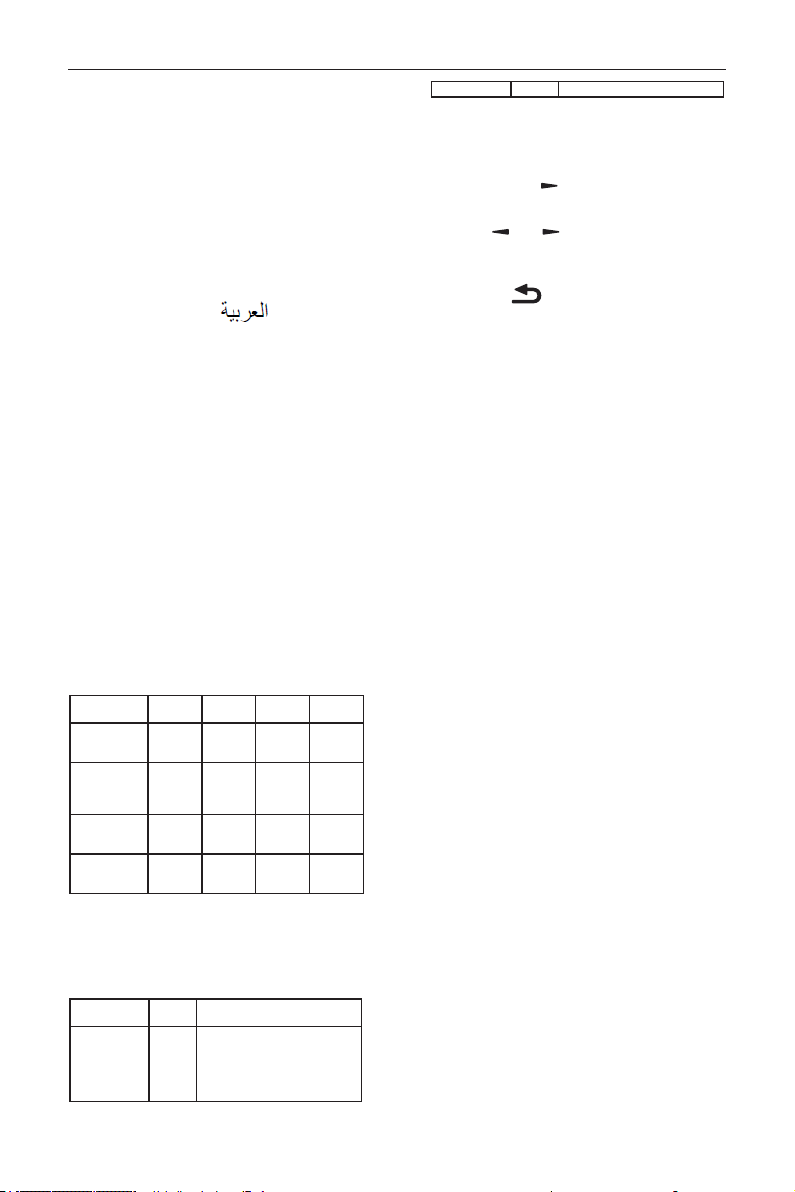
DS55MU01
40
• Back: Does not change schedule data.
• Save: Save schedule data.
HDMI with One Wire
CEC control.
• {Off} - Disable CEC.(Default)
• {On} - Enable CEC.
Language
Select the language used in the OSD menu.
The options are: English/Deutsch/
简体中文
/
Français/Italiano/Español/Pyccкий/Polski/Türkçe/
繁體
中文
/
日本語
/Português/
/Danish/Svenska/
Finnish/Norsk/Nederlands.
OSD Transparency
Adjust OSD transparency.
• {Off} - Transparency off.
• {1-100} - Transparency level 1-100.
Power Save
Mode 1 [TCP off, WOL on, auto off]
Mode 2 [TCP off, WOL on, auto on/off]
Mode 3 [TCP on, WOL off, auto on/off]
Mode 4 [TCP on, WOL off, no auto on/off]
Power save modes
Mode 1: DC off -> Power off. LED: Red.
Mode 3: DC off -> Back light off, LED: Red
Mode 4: DC off -> Back light off, LED: Red
Power Save -> Will not enter power save mode.
show “no signal” only.
RCU Power
Button Off
No Signal WoL Android
(ARM)
Mode 1 [TCP off,
WOL on, auto
off]
DC OFF DC OFF V ARM OFF
Mode 2 [TCP off,
WOL on, auto
on/off] (gary out)
DC OFF When
signal is
back, system
wake up
V ARM OFF
Mode 3 [TCP off,
WOL off, auto on/
off]
Backlight
OFF
Backlight
OFF
X ARM OFF
Mode 4 [TCP off,
WOL off, no auto
on/off]
Backlight
OFF
Backlight
ON, show
no signal
X ARM OFF
* This product does not support Mode 2
Following table is the action for Android board with
different power mode.
DC off/on: press power button by RC
Power mode in
OSD
Mode 1/2 Mode 3/4
DC off shutdown 1. The current source APK(such
as MediaPlayer, Broswer, PDF or
SmartCMS) will be closed.
2. Android system will go to the default
black launcher.
DC on Boot up 1. Android system reboots
Advanced option reset
Reset all settings except {Date and Time} in the
Advanced option menu to factory preset values.
1. Press [OK] or
[
]
button to enter the
submenu.
2. Press
[
]
or
[
]
button to select {Reset}
and press the [OK] button to restore settings to
factory preset values.
3.
Press the [
] button or select {Cancel} and
press the [OK] button to cancel and then return
to the previous menu.
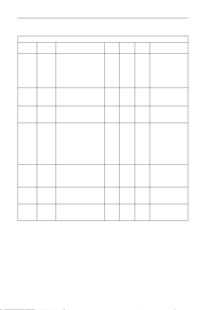
DS55MU01
41
7. Supported Media Formats
USB Multimedia Codec Formats
Video Decode
Type
Video
Codec
Container Decode Encode Channel Remark
MPEG1/2 MPEG1/2
MPEG program stream (.DAT,
.VOB, .MPG, .MPEG)
MPEG transport stream (.ts, .trp)
MP4 (.mp4, .mov)
AVI (.avi)
MKV (.mkv)
V
Max Resolution:
1080P@60fps
Max Bit Rats : 40Mbps
MPEG-4 MPEG4
MP4 (.mp4, .mov)
AVI (.avi)
MKV (.mkv)
V
Max Resolution:
1080P@60fps
Max Bit Rats : 40Mbps
H.263 H.263
FLV (.v)
AVI (.avi)
V
Max Resolution:
1080P@60fps
Max Bit Rats : 40Mbps
H.264 H.264
FLV (.v)
MP4 (.mp4, .mov)
MPEG transport stream (.ts, .trp)
ASF (.asf)
WMV (.wmv)
AVI (.avi)
MKV (.mkv)
V
Max Resolution:
1080P@60fps
Max Bit Rats : 135Mbps
4k2k@30fps
H.265 H.265
MP4 (.mp4, .mov)
MPEG transport stream (.ts,
.trp)
MKV (.mkv)
V
Max Resolution:
4K2K@60fps
Max Bit Rats : 100Mbps
GOOGLE
VP8
VP8 MKV (.mkv) WebM (.webm) V
Max Resolution:
1080P@30fps
Max Bit Rats : 20Mbps
Motion
JPEG
MJPEG
AVI (.avi)
MP4 (.mp4, .mov) MKV (.mkv)
Max Resolution:
1920*1080 @30fps
Max Bit Rats : 40Mbps

DS55MU01
42
Audio Decode
Type Audio Codec Container Decode Encode Channel Remark
MPEG Audio
MPEG1/2/2.5 Audio
Layer1/2/3
MP3 V 2
Bit Rate: 8kbps~320Kbps
Sampling Rate:
16KHZ~48KHz
Windows
Media Audio
WMA Version 7, 8,
9,10 pro M0, 10Pro
M1,M10 Pro M2
Decode:
WMA
V 2
Bit Rate: 8kbps~768Kbps
Sampling Rate:
8KHZ~96(M10)KHz
Non-support LBR
AAC Audio
MAIN, ADIF ,ATDS
Header AAC-LC
and AAC-HE
File Format:
AAC, M4A
V 5.1
Bit Rate: N/A
Sampling Rate:
8KHZ~48KHz

DS55MU01
43
Image Decode
Type
Image
Codec
Photo Decode Encode Channel Remark
JPEG
JFIF le
format 1.02
File
Format:
JPG, JPEG
V
Max Resolution: 7000 x 7000
The limitation of max resolution depends on
DRAM
BMP BMP
File
Format:
BMP
V
Max Resolution: 15360 x 8640
The limitation of max resolution depends on
DRAM
PNG PNG
File
Format:
PNG
V
Max Resolution: 15360 x 8640
The limitation of max resolution depends on
DRAM
NOTES:
• Sound or video may not work if the contents have a standard bit rate/frame rate above the compatible Frame/sec
listed in the table above.
• Video content with a Bit rate or Frame rate larger than the rate specied in the table above can cause choppy
video during playback.
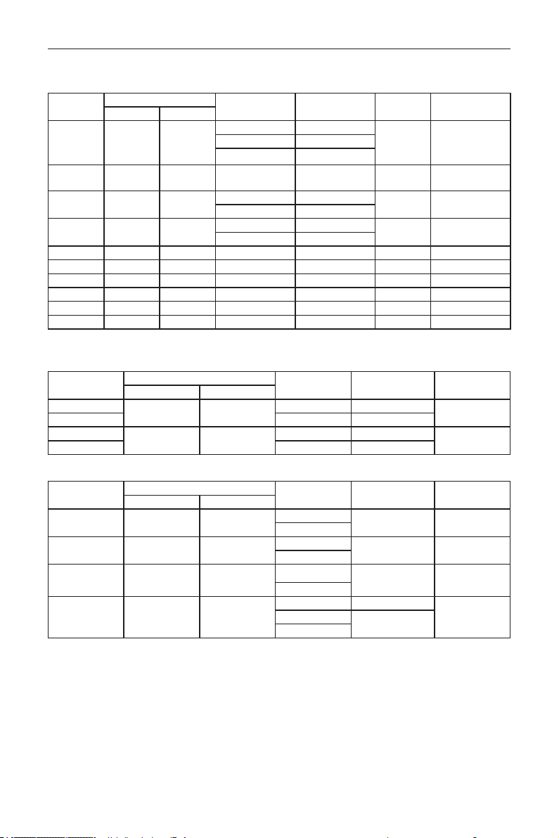
DS55MU01
44
8. Input Mode
VGA Resolution:
Standard
Resolution
Active Resolution
Refresh Rate Pixel Rate Aspect Ratio Stand for Mode
H Pixels V Lines
VGA 640 480
60 Hz 25.175 MHz
4:3
Video Graphic
Array
72 Hz 31.5 MHz
75 Hz 31.5 MHz
WVGA 720 400 70 Hz 33.75 MHz 16:9
Wide Video
Graphic Array
SVGA 800 600
60 Hz 40 MHz
4:3 Super VGA
75 Hz 49.5 MHz
XGA 1024 768
60 Hz 65 MHz
4:3
Extended Graphic
Array
75 Hz 78.75 MHz
WXGA 1280 768 60 Hz 79.5 MHz 5:3 Wide XGA
WXGA 1280 800 60 Hz 79.5 MHz 16:10 Wide XGA
SXGA 1280 1024 60 Hz 108 MHz 5:4 Super XGA
WXGA 1360 768 60 Hz 85.5 MHz 16:9 Wide XGA
UXGA 1600 1200 60 Hz 162 MHz 4:3 Ultra XGA
HD1080 1920 1080 60 Hz 148.5 MHz 16:9 HD1080
Note: 1280x768@60Hz can be supported but not shown in EDID table.
SD Resolution:
Standard
Resolution
Active Resolution
Refresh Rate Pixel Rate Aspect Ratio
H Pixels V Lines
480i
720 480
29.97 Hz 13.5 MHz
4:3
480p 59.94 Hz 27 MHz
576i
720 576
25 Hz 13.5 MHz
4:3
576p 50 Hz 27 MHz
HD Resolution:
Standard
Resolution
Active Resolution
Refresh Rate Pixel Rate Aspect Ratio
H Pixels V Lines
720p 1280 720
50 Hz
74.25 MHz 16:9
60 Hz
1080i 1920 1080
25 Hz
74.25 MHz 16:9
30 Hz
1080p 1920 1080
50 Hz
148.5 MHz 16:9
60 Hz
2160p (HDMI
only)
3840 2160
30 Hz 297 MHz
16:950 Hz
594 MHz
60 Hz
• The PC text quality is optimum in HD 1080 mode (1920 x 1080, 60Hz).
• Your PC display screen might appear different depending on the manufacturer (and your particular version of
Windows).
• Check your PC instruction book for information about connecting your PC to a display.
• If a vertical and horizontal frequency-select mode exists, select 60Hz (vertical) and 31.5KHz (horizontal). In some
cases, abnormal signals (such as stripes) might appear on the screen when the PC power is turned off (or if the
PC is disconnected). If so, press the [INPUT] button to enter the video mode. Also, make sure that the PC is
connected.

DS55MU01
45
• When horizontal synchronous signals seem irregular in RGB mode, check PC power saving mode or cable
connections.
• The display settings table complies to the IBM/VESA standards, and based on the analog input.
• The DVI support mode is regarded as same to the PC support mode.
• The best timing for the vertical frequency to each mode is 60Hz.

DS55MU01
46
9. Cleaning and Troubleshooting
9.1. Cleaning
Caution When Using the Display
• Do not bring your hands, face or objects close to the ventilation holes of the display. The top of the display
is usually very hot due to the high temperature of exhaust air being released through the ventilation holes.
Burns or personal injuries may occur if any body parts are brought too close. Placing any object near the top
of the display could also result in heat related damage to the object as well as the display itself.
• Be sure to disconnect all cables before moving the display. Moving the display with its cables attached may
damage the cables and thus cause re or electric shock.
• Disconnect the power plug from the wall outlet as a safety precaution before carrying out any type of
cleaning or maintenance procedure.
Front Panel Cleaning Instructions
• The front of the display has been specially treated. Wipe the surface gently using only a cleaning cloth or a
soft, lint-free cloth.
• If the surface becomes dirty, soak a soft, lint-free cloth in a mild detergent solution. Wring the cloth to remove
excess liquid. Wipe the surface of the display to remove dirt. Then use a dry cloth of the same type to dry.
• Do not scratch or hit the surface of the panel with ngers or hard objects of any kind.
• Do not use volatile substances such as insert sprays, solvents and thinners.
Cabinet Cleaning Instructions
• If the cabinet becomes dirty, wipe the cabinet with a soft, dry cloth.
• If the cabinet is extremely dirty, soak a lint-free cloth in a mild detergent solution. Wring the cloth to remove
as much moisture as possible. Wipe the cabinet. Use another dry cloth to wipe over until the surface is dry.
• Do not allow any water or detergent to come into contact with the surface of the display. If water or
moisture gets inside the unit, operating problems, electrical and shock hazards may result.
• Do not scratch or hit the cabinet with ngers or hard objects of any kind.
• Do not use volatile substances such as insert sprays, solvents and thinners on the cabinet.
• Do not place anything made from rubber or PVC near the cabinet for any extended periods of time.
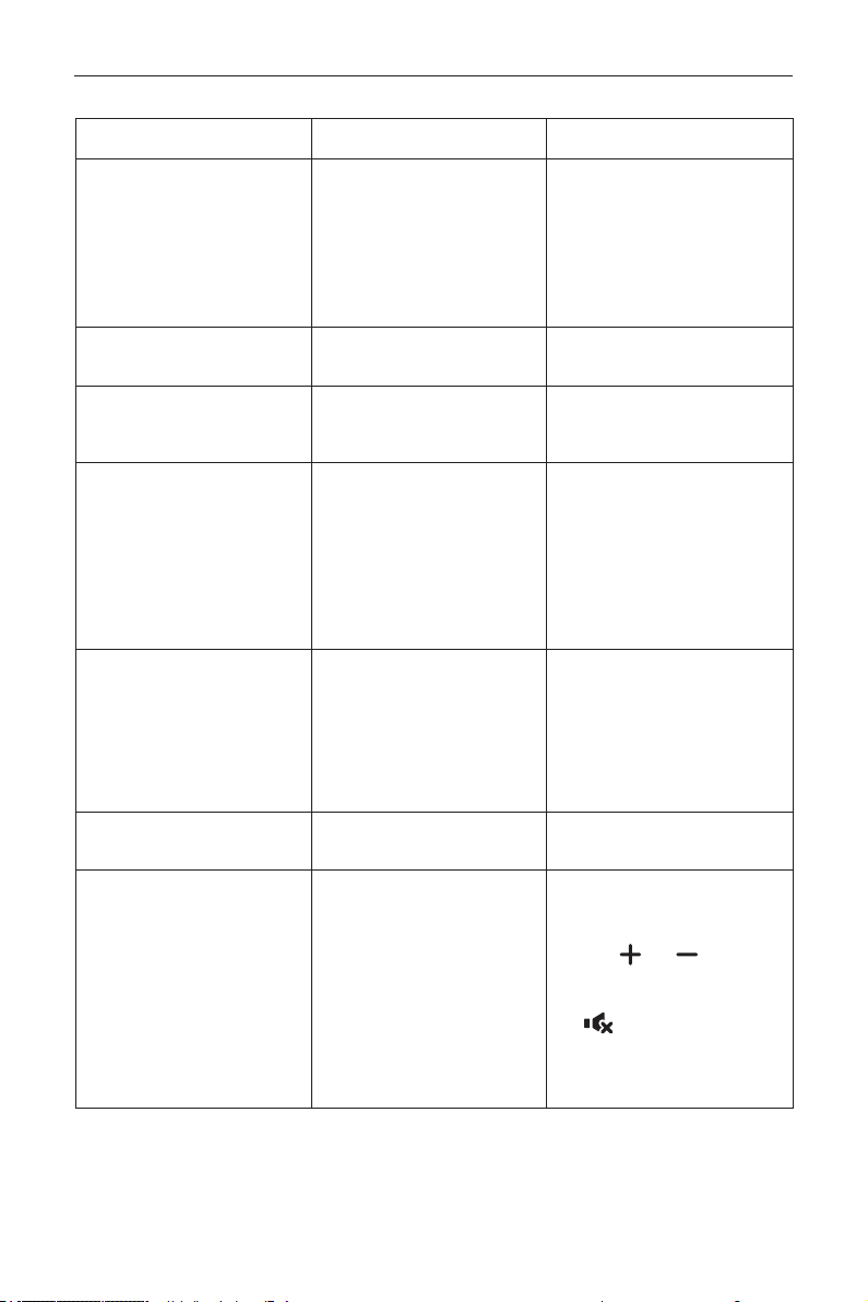
DS55MU01
47
9.2. Troubleshooting
Symptom Possible Cause Remedy
No picture is displayed
1. The power cord is disconnected.
2. The main power switch on
the back of the display is not
switched on.
3. The selected input has no
connection.
4. The display is in standby mode.
1. Plug in the power cord.
2. Make sure the power switch is
switched on.
3. Connect a signal connection to the
display.
Interference displayed on the display
or audible noise is heard
Caused by surrounding electrical
appliances or uorescent lights.
Move the display to another location
to see is the interference is reduced.
Color is abnormal The signal cable is not connected
properly.
Make sure that the signal cable is
attached rmly to the back of the
display.
Picture is distorted with abnormal
patterns
1. The signal cable is not connected
properly.
2. The input signal is beyond the
capabilities of the display.
1. Make sure that the signal cable is
attached rmly.
2. Check the video signal source
to see if it is beyond the range
of the display. Please verify its
specications with this display’s
specication section.
Displayimagedoesn’tllupthefull
size of the screen
1. The zoom mode is not set
correctly.
2. Scan Mode may be set
incorrectly to underscan.
3. If the image exceeds the screen
size, Scan Mode may need to be
set to Underscan.
Use the Zoom mode or Custom
zoom function in the Screen menu to
ne tune display geometry and time
frequency parameter.
Can hear sound, but no picture Improperly connected source signal
cable.
Make sure that both video inputs and
sound inputs are correctly connected.
Can see picture but no sound is
heard
1. Improperly connected source
signal cable.
2. Volume is turned all the way
down.
3. {Mute} is turned on.
4. No external speaker connected.
1. Make sure that both video inputs
and sound inputs are correctly
connected.
2. Press
[
]
or
[ ]
button to
hear sound.
3. Switch MUTE off by using the
[
]
button.
4. Connect external speakers and
adjust the volume to a suitable
level.

DS55MU01
48
Some picture elements do not light
up
Some pixels of the display may not
turn on.
This display is manufactured using
an extremely high level of precision
technology: however, sometimes some
pixels of the display may not display.
This is not a malfunction.
After-Images can still be seen
on the display after the display
is powered off. (Examples of still
pictures include logos, video games,
computer images, and images
displayed in 4:3 normal mode)
A still picture is displayed for an over
extended period of time
Do not allow a still image to be
displayed for an extended period of
time as this can cause a permanent
after-image to remain on the display.
How to setup the settings in the
menu to control all the monitors at
the same time and individually via
RC?
Daisy chained by RS232 and no IR
cable
1. The rst display sets as “Primary”
on OSD (Advanced option/IR control
item), others set as “Secondary”.
2. The setup OSD will show on Top-
Left of display.(Toggle MENU will show
again if it disappear)
3. Default setting: ID NO: 0, GP NO: 0,
this setting can control all displays by
IR.
The “+”, “-” can change “ID NO” to
control signal display by “Monitor ID”.
The “UP”, “DOWN” can change “GP
NO” to control multi-display by “Group
ID”.
*The rst display always be
controlled by IR.
How is the RC working? Daisy chain : no RS232 connected
and IR cable
No need setting, just to connect with
IR cables and control by IR.
*This way has out-of-synchronizm
phenomenon. Suggest to use above
setting with RS-232 cable.
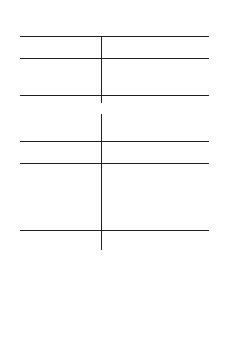
DS55MU01
49
10. Technical Specifications
Display:
Item Specications
Screen Size (Active Area) 138.7 cm / 54.6 inch
Aspect Ratio 16:9
Number of pixels 3840 (H) x 2160 (V)
Pixel pitch 0.315 (H) x 0.315 (V) [mm]
Displayable colors 10 bits(D), 1.07 Billion colors
Brightness (typical) 350 cd/m
2
Contrast ratio (typical) 4000:1
Viewing angle 178 degrees
In/Out Terminals:
Item Specications
Speaker Output Internal Speakers 10W (L) + 10W (R) [RMS]/8Ω
1 Way 1 Speaker System
82 dB/W/M/160 Hz ~ 13 KHz
Audio Output RCA R/L x 1 0.5V [rms] (Normal) / 2 Channel (L+R)
Audio Input 3.5mm phone jack x 1 0.5V [rms] (Normal) / 2 Channel (L+R)
RS232C 2.5mm Phone jack x 2 RS232C in/RS232C out
RJ-45 RJ-45 Jack x 1 (8 pin) 10/100 LAN Port
HDMI Input HDMI Jack x 2
(Type A) (19 pin)
Digital RGB: TMDS (Video + Audio)
MAX:
Video - 720p, 1080p, 3840 x 2160/60 Hz
Audio - 48 KHz/ 2 Channel (L+R)
Supports LPCM only
VGA Input D-SUB jack (15pin) Digital RGB: TMDS (Video)
Analog RGB: 0.7V [p-p] (75Ω), H/CS/V: TTL (2.2kΩ), SOG: 1V [p-
p] (75Ω)
MAX: 1920 x 1080/60 Hz (WUXGA)
DVI Input DVI Jack x 1 Digital RGB: TMDS (Video)
IR Input/Output 3.5mm x 2 IR pass through or IR daisy chain
USB Input USB x 2 (Type A) USB 2.0, Multimedia play and service port / USB 3.0, Multimedia
play only
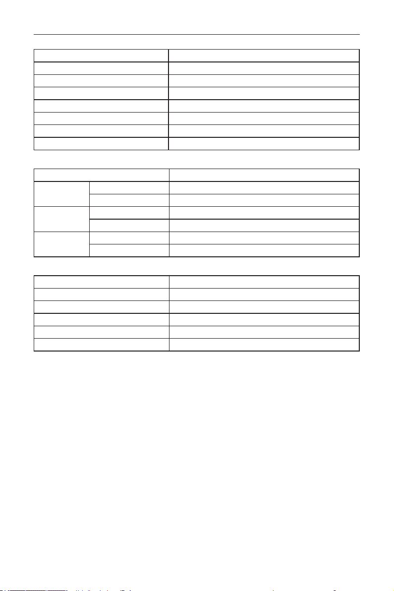
DS55MU01
50
General:
Item Specications
Power Input 100 - 240V~, 50 - 60Hz, 2.5A
Power Consumption (Max) 190 W
Power Consumption (typ.) 145 W
Power Consumption (Standby & Off)
<0.5 W
Dimensions (Without Stand) [W x H x D] 1239.2 x 727 x 61.7 mm
Weight (Without Stand) 15.96 Kg
Gross Weight (Without Stand) 23.0 Kg
Environmental Condition:
Item Specications
Temperature Operational 0 ~ 40°C
Storage -20 ~ 60°C
Humidity Operational 20 ~ 80% RH (No condensation)
Storage 5 ~ 95% RH (No condensation)
Altitude Operational 0 ~ 3,000 m
Storage / Shipment 0 ~ 9,000 m
Internal Speaker:
Item Specications
Type 1 Way 1 Speaker
Input 10 W (RMS)
Impedance 8Ω
Output Sound Pressure 82 dB/W/M
Frequency Response 160 Hz ~ 13 KHz


Q41G55M177901A