Loading ...
Loading ...
Loading ...
Section 4 - REPAIR & ADJUSTMENTS
WARNING I
Before attempting any adjustments or repairs, STOP I
the engine, remove the spark plug wire from the I
spark plug and secure wire away from plug. I
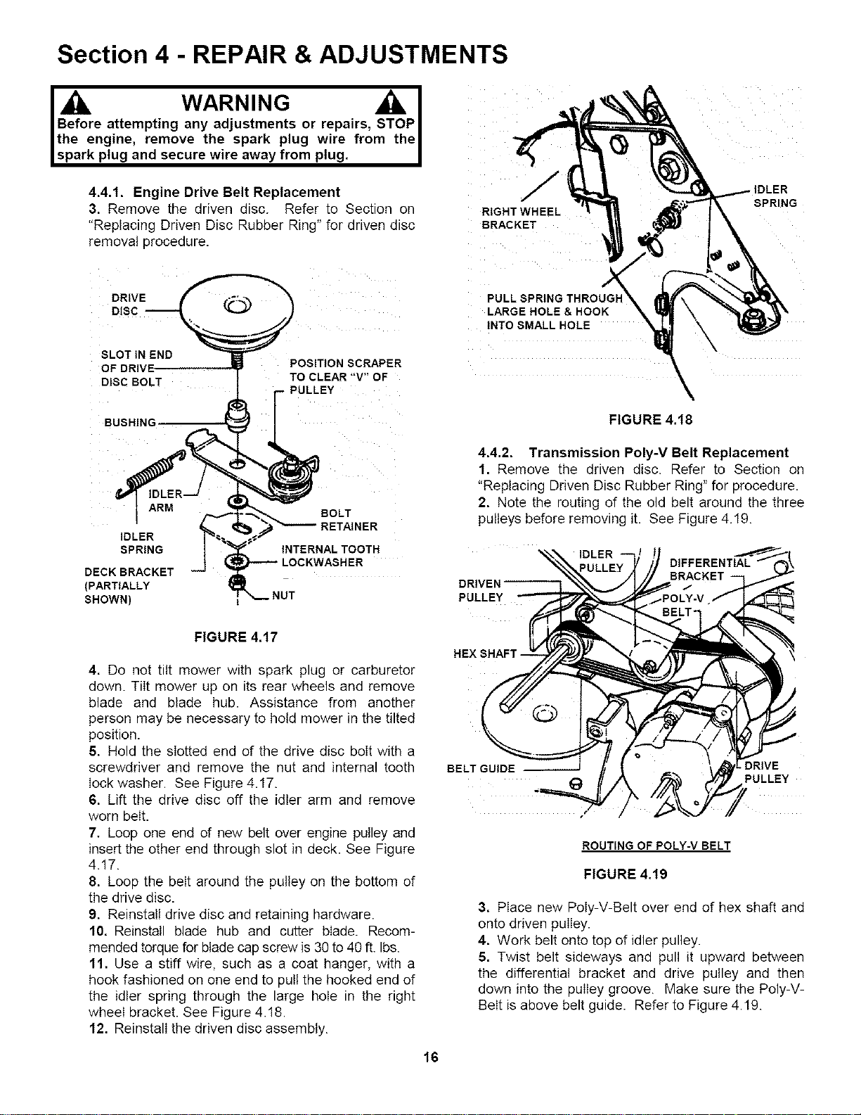
4.4.1. Engine Drive Belt Replacement
3. Remove the driven disc. Refer to Section on
"Replacing Driven Disc Rubber Ring" for driven disc
removal procedure.
RIGHT WHEEL
BRACKET
SPRING
DRIVE
DISC
SLOT IN END
DISC BOLT
POSITION SCRAPER
TO CLEAR "V" OF
PULL SPRING THROUGI"
LARGE HOLE & HOOK
INTO SMALL HOLE
BUSHING
ARM
IDLER
SPRING
DECK BRACKET
(PARTIALLY
SHOWN)
BOLT
RETAINER
INTERNAL TOOTH
NUT
FIGURE 4.t8
4.4.2. Transmission Poly-V Belt Replacement
1. Remove the driven disc. Refer to Section on
"Replacing Driven Disc Rubber Ring" for procedure.
2. Note the routing of the old belt around the three
pulleys before removing it. See Figure 4.19.
IDLER
DRIVEN
PULLEY
FIGURE 4.17
4, Do not tilt mower with spark plug or carburetor
down. Tilt mower up on its rear wheels and remove
blade and blade hub. Assistance from another
person may be necessary to hold mower in the tilted
position.
5. Hold the slotted end d the drive disc bolt with a
screwdriver and remove the nut and internal tooth
lock washer. See Figure 4.17.
6, Lift the drive disc off the idler arm and remove
worn belt.
7. Loop one end of new belt over engine pulley and
insert the other end through slot in deck. See Figure
4.17.
8. Loop the belt around the pulley on the bottom of
the drive disc.
9, Reinstall drive disc and retaining hardware.
10, Reinstall blade hub and cutter blade. Recom-
mended torque for blade cap screw is 30 to 49 ft. Ibs.
11, Use a stiff wire, such as a coat hanger, with a
hook fashioned on one end to pull the hooked end of
the idler spring through the large hole in the right
wheel bracket. See Figure 4.18.
12. Reinstall the driven disc assembly.
HEX SHAFT -
BELT GUIDE DRIVE
PULLEY
ROUTING OF POLY-V BELT
FIGURE 4.19
3, Place new Poly-V-Belt over end of hex shaft and
onto driven pulley.
4. Work belt onto top of idler pulley.
5, Twist belt sideways and pull it upward between
the differential bracket and drive pulley and then
down into the pulley groove. Make sure the Poly-V-
Belt is above belt guide. Refer to Figure 4.19.
18
Loading ...
Loading ...
Loading ...