Loading ...
Loading ...
Outdoor unit installation
Air inlet
Air outlet
40 mm
2-10 mm × 21 mm slot
800 mm
150 mm
500 mm
344.5 mm
285 mm
304-325 mm
(G)
(E)
(C)
(4)
(D)
(F)
(B)
(K)
(A)
(I)
(7)
(3)
(8)
(6)
(5)
(2)
(1)
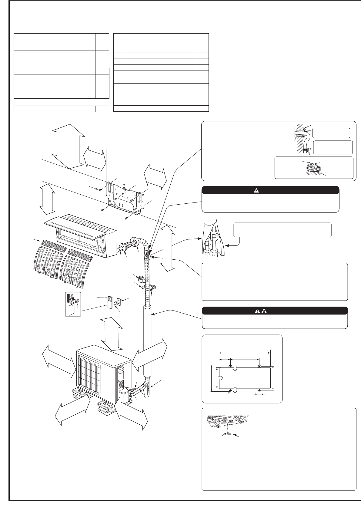
1-4. INSTALLATION DIAGRAM
When the piping is to be attached to a wall containing metals (tin plated) or metal
netting, use a chemically treated wooden piece 20 mm or thicker between the
wall and the piping or wrap 7 to 8 turns of insulation vinyl tape around the piping.
To use existing piping, perform COOL operation for 30 minutes and pump
GRZQEHIRUHUHPRYLQJWKHROGDLUFRQGLWLRQHU5HPDNHÀDUHDFFRUGLQJWRWKH
dimension for new refrigerant.
Appearance of the outdoor unit may differ from some models.
60 mm
or more
1.8 m to 2.3 m from the
ÀRRULVUHFRPPHQGHG
clear *2
100 mm
or more
100 mm
or more
200 mm *3
or more
*2 100 mm or more when front and sides
of unit are clear
Note:
*1 Place indoor/outdoor unit connecting wire (A) and
power supply cord (K) at least 1 m away from the TV
antenna wire.
After the leak test, apply insulating material tightly
so that there is no gap.
7RDYRLGULVNRI¿UHHPEHGRUSURWHFWWKHUHIULJHUDQWSLSLQJ
([WHUQDOGDPDJHRQWKHUHIULJHUDQWSLSLQJFDQEHFDXVHRI¿UH
(9)
(I)
PARTS TO BE PROVIDED AT YOUR SITE
(A) Indoor/outdoor unit connecting wire*1
1
% Extension pipe
1
(C) Wall hole sleeve
1
' Wall hole cover
1
(E) 3LSH¿[LQJEDQG
2 to 5
(F) Fixing screw for (E) 4 × 20 mm
2 to 5
(G) Piping tape
1
(H) Putty
1
(I)
'UDLQKRVH
(or soft PVC hose, 15 mm inner
diameter or hard PVC pipe VP16)
1 or 2
(J) Refrigeration oil
1
(K) Power supply cord*1
1
ACCESSORIES
Check the following parts before installation.
<Indoor unit>
(1) Installation plate
1
(2)
,QVWDOODWLRQSODWH¿[LQJVFUHZ
4 × 25 mm
5
(3) Wireless remote controller
1
(4)
Felt tape
(For left or left-rear piping)
1
(5) Remote controller holder
1
(6)
Fixing screw for (5) 3.5 × 16 mm
%ODFN
2
(7) %DWWHU\$$$IRU
2
(8) $LUFOHDQLQJ¿OWHU
2
<Outdoor unit>
(9) 'UDLQVRFNHW
1
Air inlet
*3 When any 2 sides of left, right and rear of unit are clear.
IMPORTANT NOTES
Units should be installed by licensed contractor according to local code requirements.
To comply with the requirements of Australian standard AS/NZS 3000 electrical
installations (wiring rules), the electrical wiring required between the indoor and
outdoor units must be installed by a licenced electrical contractor.
Check that cabling will not be subject to wear, corrosion, excessive pressure,
vibration, sharp edges or any other adverse environmental effects. The check shall
also take into account the effects of aging or continual vibration from sources such as
compressors or fans.
61
mm or more/
138
mm or more for
left and left back piping
(using spacer)
106 mm
or more
126
mm
or more
350 mm
or more
Note:
Install the unit horizontally.
'RQRWXVHGUDLQVRFNHWLQFROGUHJLRQV'UDLQPD\IUHH]HDQGPDNHWKH
fan stop.
The outdoor unit produces condensate during the heating operation. Select
the installation place to ensure to prevent the outdoor unit and/or the grounds
from being wet by drain water or damaged by frozen drain water.
Drain piping for outdoor unit
3URYLGHGUDLQSLSLQJEHIRUHLQGRRUDQGRXWGRRUSLS-
ing connection.
&RQQHFWGUDLQKRVH,,'PPDV VKRZQLQWKH
illustration.
0DNH VXUH WR SURYLGH GUDLQ SLSLQJ ZLWK D GRZQKLOO
JUDGHIRUHDV\GUDLQÀRZ
%HVXUHWRXVHZDOOKROHVOHHYH&
to prevent indoor/outdoor connect-
ing wire (A) from contacting metal
parts in the wall and to prevent
damage by rodents in case the
wall is hollow.
Indoor unit
Wall hole
sleeve (C)
Cut off the
extra length.
3LSH¿[LQJEDQG(
:DOOKROHFRYHU'
Fixing screw (F)
Seal the wall hole
gap with putty (H).
Fix the pipe to wall
ZLWKSLSH¿[LQJEDQG
(E).
WARNING
7RDYRLGULVNRI¿UHÀDUHFRQQHFWLRQVKRXOGEHLQVWDOOHGRXWGRRUV
5HXVDEOHPHFKDQLFDOFRQQHFWRUVDQGÀDUHGMRLQWVDUHQRWDOORZHG
indoors.
WARNING
Loading ...
Loading ...
Loading ...