Owner's Manual/ManualDel Propietario
CRRFTSMRN °
GARAGEDOOROPENER
ABRIDORDEPUERTADECOCHERA
ForResidentialUse0nly/S61oparausoresidencial
Model/Modelo 139.53918D
I"11
z
I"11
'13
;Z=,
Z_
Readandfollowall safetyrulesand operating
instructionsbeforefirst use ofthis product.
Fastenthe manualnearthe garagedoorafter
installation.
Periodic checksof the opener are requiredto
ensuresafe operation.
Leery seguirtodaslas reglasde seguridady
las instruccionesde operaci6n antesde usar
este productoporprimeravez.
Guardareste manualcercade la puerta de la
cochera.
Se debenrealizar revisionesperi6dicas
del abridorde puertas para asegurarsu
operaci6n segura.
cQus
Sears, Roebuckand Co., HoffmanEstates,IL 60179 U.S.A
www.sears.com/craftsman
TABLE OF CONTENTS
Introduction 2-7
Safety symbol review and signal word review................ 2
Preparingyour garagedoor ............................. 3
Tools needed......................................... 3
Planning .......................................... 4-5
Carton inventory ...................................... 6
Hardware inventory.................................... 7
Assembly 8-11
Assemble the rail and install the trolley ..................... 8
Fastenthe rail to the motor unit .......................... 9
Install the idler pulley .................................. 9
Install the belt ....................................... 10
Tighten the belt ...................................... 10
Install the sprocket cover .............................. 11
Installation 11-26
Installation safety instructions .......................... 11
Determine the header bracket location .................... 12
Install the header bracket .............................. 13
Attach the rail to the header bracket ...................... 14
Position the opener ................................... 15
Hang the opener ..................................... 16
Install the door control ................................ 17
Install the battery .................................... 18
Install the lights ..................................... 18
Attach the emergency releaseropeand handle.............. 19
Electrical requirements ................................ 19
Install The Protector System® ....................... 20-22
Fastenthe door bracket............................. 23-24
Connect the door arm to the trolley ................... 25-26
Adjustment 27-29
Program the travel limits ............................... 27
Set the force ........................................ 28
Test the safety reversal system .......................... 29
Test The Protector System® ............................ 29
Operation 30-36
Operation safety instructions ........................... 30
Using your garagedoor opener ......................... 30
Using the wall-mounted door control ..................... 31
Careof your opener .................................. 32
To open the door manually ............................. 32
Battery backup ...................................... 33
Having a problem (Troubleshooting) ..................... 34
Diagnostic chart ..................................... 35
Smart Control Panel® messages......................... 36
Programming 37-38
To add or reprogram a hand-held remote control ............ 37
To erase all codesfrom motor unit memory ................ 37
3-Button remotes .................................... 37
To add, reprogram or change a
Keyless Entry PIN .................................... 38
Repair Parts 39-40
Rail assemblyparts................................... 39
Installation parts ..................................... 39
Motor unit assembly parts ............................. 40
Accessories 41
Warranty 41
Repair Parts & Service Back Cover
INTRODUCTION
Safety SymbolReviewand Signal WordReview
This garage door opener has been designed and tested to offer safe service provided it is installed, operated,maintained and tested in
strict accordancewith the instructions and warnings contained in this manual.
Mechanical
Electrical
When you see these Safety Symbols and Signal Words on the
following pages,they will alert you to the possibility of serious
injury or deathif you do not comply with the warnings that
accompanythem. The hazard may come from something
mechanical or from electric shock. Readthe warnings carefully.
When you see this Signal Word on the following pages, it will
alert you to the possibility of damageto your garagedoor and/or
the garagedoor opener if you do not comply with the cautionary
statements that accompany it. Readthem carefully.
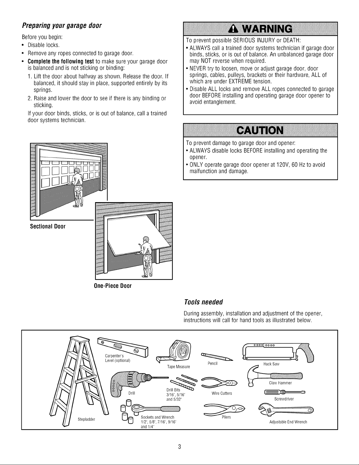
Preparingyourgarage door
Before you begin:
• Disable locks.
• Removeany ropes connected to garage door.
• Completethe followingtest to makesure your garagedoor
is balancedand is not sticking or binding:
1. Lift the door about halfway as shown. Releasethe door. If
balanced,it should stay in place, supported entirely by its
springs.
2. Raiseand lower the door to see if there is any binding or
sticking.
If your door binds, sticks, or is out of balance, call a trained
door systems technician.
To prevent possible SERIOUSINJURYor DEATH:
• ALWAYScall a trained door systems technician if garage door
binds, sticks, or is out of balance.An unbalanced garage door
may NOT reverse when required.
• NEVERtry to loosen, move or adjust garagedoor, door
springs, cables, pulleys, brackets or their hardware, ALL of
which are under EXTREMEtension.
• DisableALL locks and remove ALL ropes connected to garage
door BEFOREinstalling and operating garage door opener to
avoid entanglement.
To prevent damage to garage door and opener:
• ALWAYSdisable locks BEFOREinstalling and operating the
opener.
• ONLY operate garage door opener at 120V, 60 Hz to avoid
malfunction and damage.
SectionalDoor
One-Piece Door
Tools needed
During assembly, installation and adjustment of the opener,
instructions will call for handtools as illustrated below.
Stepladder
Level (optional)
Tape Measure
Drill 3/16", 5/16"
and 5/32"
8_ _/°2c'_e5t/s8"a,7d/1W"r,e_/Clh"
and 1/4"
Pencil Hack Saw
Wire Cutters
Pliers
Claw Hammer
Screwdriver
Adjustable End Wrench
P_nnmg
Identify the type and height of your garagedoor. Survey your
garagearea to see if any of the conditions below apply to your
installation. Additional materials may be required. You may find it
helpful to refer back to this pageand the accompanying
illustrations as you proceed with the installation of your opener.
Depending on your requirements, there are several installation
steps which may call for materials or hardware not included in
the carton.
• Installation Step 1 - Look at the wall or ceiling above the
garagedoor. The header bracket must be securely fastened to
structural supports.
• Installation Step 5 - Do you have a finished ceiling in your
garage? If so, a support bracket and additional fastening
hardware may be required.
• Installation Step 11 - Dependingupon garageconstruction,
extension brackets or wood blocks may be needed to install
sensors.
• Installation Step 11 - Alternate floor mounting of the safety
reversingsensor will require hardware not provided.
Doyou have an access door in addition to the garagedoor? If
not, Model 139.53702 Emergency Key Releaseis required. See
Accessories page.
Look at the garage door where it meets the floor. Any gap
betweenthe floor and the bottom of the door must not exceed
1/4" (6 mm). Otherwise, the safety reversal system may not
work properly. SeeAdjustment Step 3. Floor or door should be
repaired.
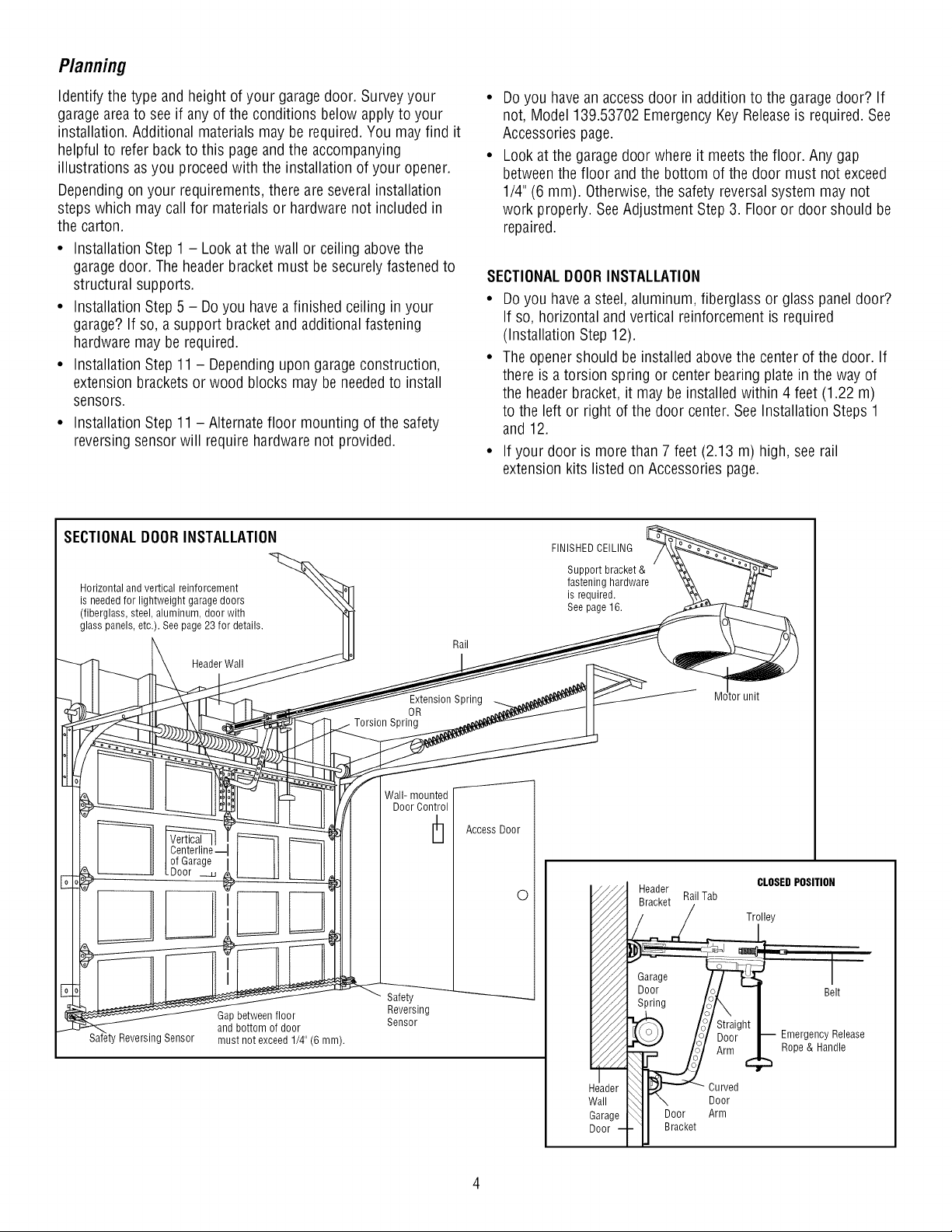
SECTIONALDOORINSTALLATION
• Doyou have a steel, aluminum, fiberglass or glass panel door?
If so, horizontal and vertical reinforcement is required
(Installation Step 12).
• The opener should be installed above the center of the door. If
there is a torsion spring or center bearing plate in the way of
the header bracket, it may be installed within 4 feet (1.22 m)
to the left or right of the door center. See Installation Steps 1
and 12.
• If your door is more than 7 feet (2.13 m) high, see rail
extension kits listed on Accessories page.
SECTIONALDOORINSTALLATION
Horizontal and vertical reinforcement
is needed for lightweight garage doors
(fiberglass, steel, aluminum, door with
glass panels, etc.). See page 23 for details.
Header Wall
Reversing Sensor
of Garage
.Door
Gap between floor
and bottom of door
must not exceed 1/4" (6 mm).
Rail
Extension Spring
OR
Torsion Spring
Wall- mounted
Door Control
Safety
Reversing
Sensor
Access Door
©
FINISHED CEILING
Support bracket &
fastening hardware
is required.
See page16.
tor unit
Header
Bracket Rail Tab
CLOSEDPOSITION
Trolley
Header Curved
Wall Door
Garage Door Arm
Door Bracket
Belt
Emergency Release
Rope & Handle
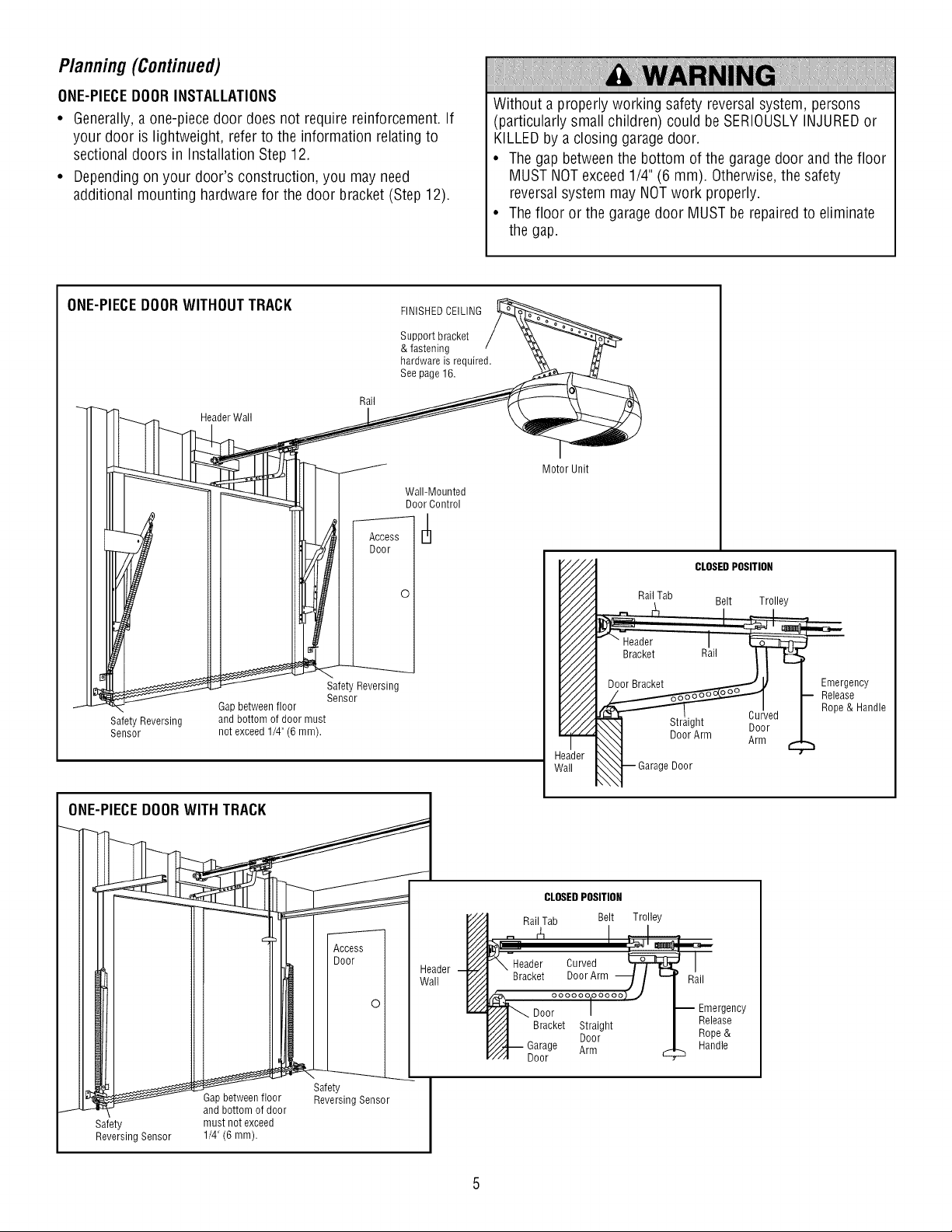
Planning(Continued)
ONE-PIECEDOORINSTALLATIONS
• Generally,a one-piece door does not require reinforcement. If
your door is lightweight, refer to the information relating to
sectional doors in Installation Step 12.
• Dependingon your door's construction, you may need
additional mounting hardware for the door bracket (Step 12).
Without a properly working safety reversal system, persons
(particularly small children) could be SERIOUSLYINJUREDor
KILLEDby a closing garagedoor.
• The gap betweenthe bottom of the garage door and the floor
MUST NOT exceed 1/4" (6 mm). Otherwise,the safety
reversalsystem may NOTwork properly.
• The floor or the garage door MUST be repairedto eliminate
the gap.
ONE-PIECEDOORWITHOUTTRACK
SafetyReversing
Sensor
Header Wall
Rail
Access
Door
o
Safety Reversing
Sensor
Gap between floor
and bottom of door must
not exceed 1/4" (6 mm).
FINISHEDCEILING
Support bracket
& fastening
hardware is required.
See page 16.
Wall-Mounted
Door Control
Motor Unit
CLOSEDPOSITION
Rail Tab Belt Trolley
eader
_all Door
Cul
Door
Arm
Emergency
Release
Rope & Handle
ONE-PIECEDOORWITH TRACK
Gapbetween floor
and bottom of door
Safety must not exceed
Reversing Sensor 1/4" (6 mm).
Access
Door
Safety
Reversing Sensor
Header
Wall
CLOSEDPOSITION
Rail Tab Belt Trolley
Door
Straight
Door
Arm
Rail
Emergency
Release
Rope &
Handle
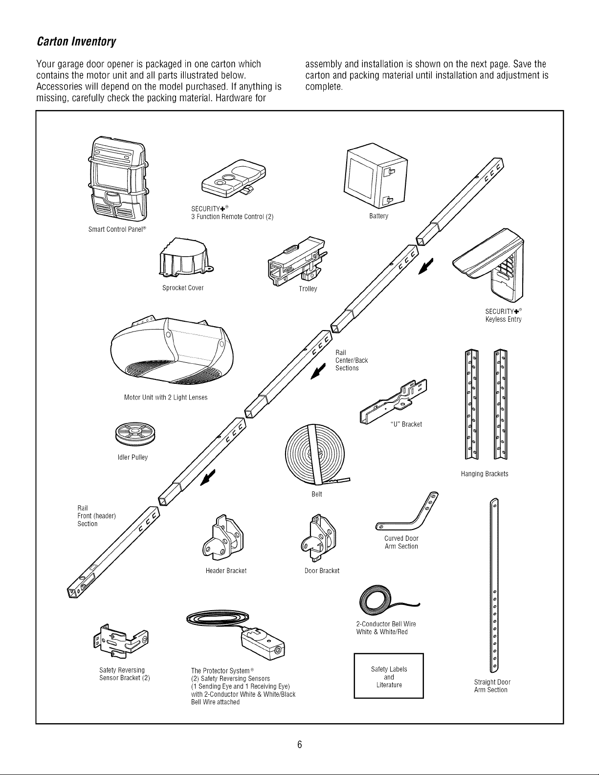
CartonInventory
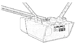
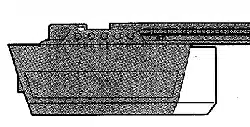
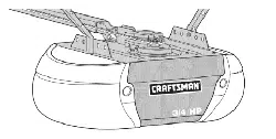
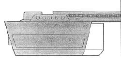
Your garage door opener is packagedin one carton which
contains the motor unit and all parts illustrated below.
Accessories will depend on the model purchased. If anything is
missing, carefully check the packing material. Hardwarefor
assembly and installation is shown on the next page. Save the
carton and packing material until installation and adjustment is
complete.
Smart Control Panel®
SECURITY+ ®
3 Function Remote Control (2)
Sprocket Cover
Trolley
Battery
Motor Unit with 2 Light Lenses
Rail
Center/Back
Sections
Rail
Front (header)
Section
Idler Pulley
Header Bracket
Belt
Door Bracket
Safety Reversing
Sensor Bracket (2)
The Protector System <'_
(2) Safety Reversing Sensors
(1 Sending Eye and 1 Receiving Eye)
with 2-Conductor White & White/Black
Bell Wire attached
/
Curved Door
Arm Section
2-Conductor Bell Wire
White & White/Red
Safety Labels
and
Literature
SECURITY÷®
Keyless Entry
Io
i 1°
_PI,,
Io
Io
%
Hanging Brackets
Straight Door
Arm Section
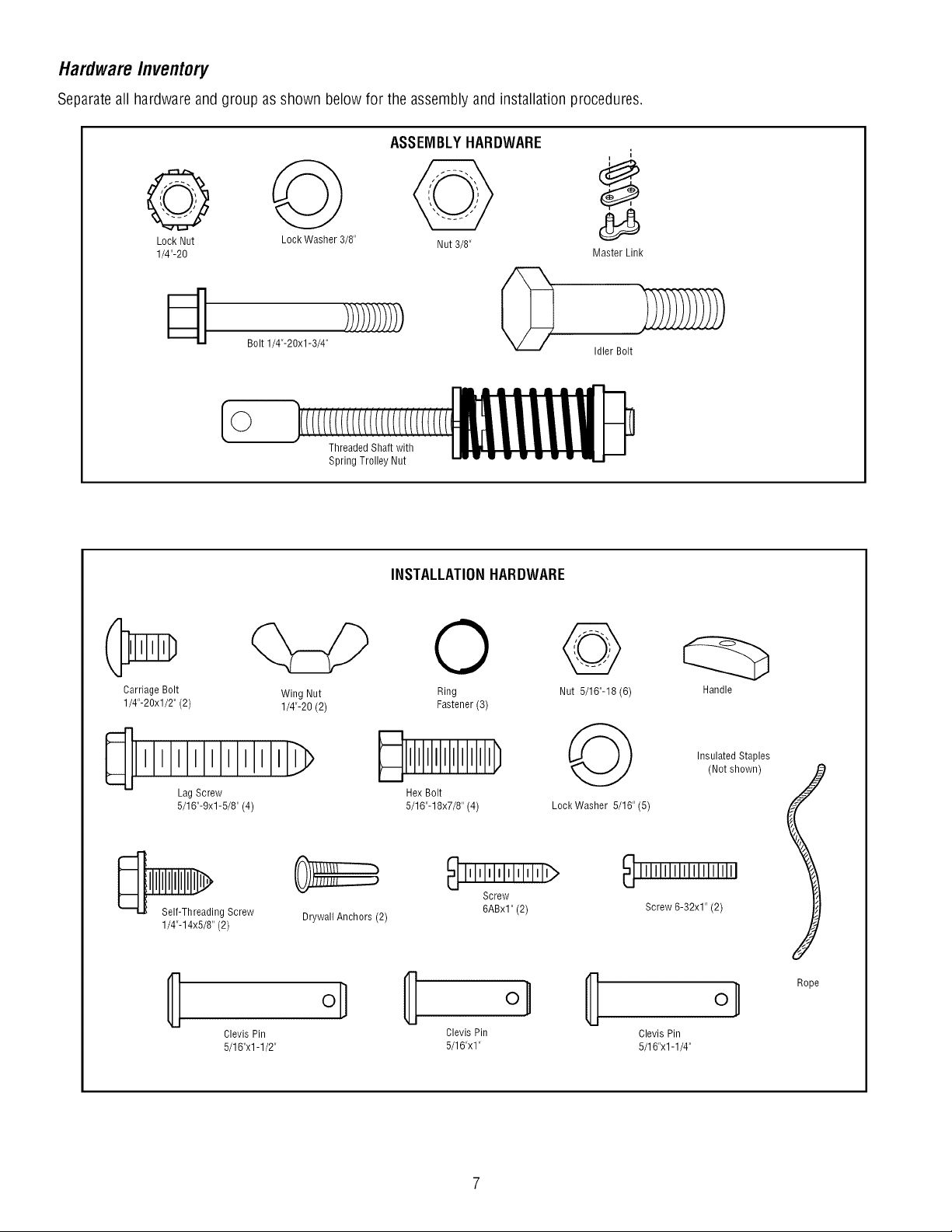
HardwareInventory
Separateall hardware and group as shown below for the assembly and installation procedures.
ASSEMBLYHARDWARE
i
i
e O @
Lock Nut Lock Washer 3/8" Nut 8/8"
]/4"-20 Master Link
_] Bolt 1/4"-20xl-3/4" !!!)!_}}!_ 0
Idler Bolt
Threaded Shaft with
Spring Trolley Nut
INSTALLATIONHARDWARE
Carriage Bolt Wing Nut
1/4"-20xl/2" (2) 1/4"-20 (2)
_]IIIIIIIIIILI _
Lag Screw
5/16"-9xl-5/8" (4)
_ng Screw
1/4"-14x5/8" (2)
Drywall Anchors (2)
0
Ring
Fastener (3)
Hex Bolt
5/16"-18x7/8" (4)
_lllllllllllllllllb
Screw
6ABxl"(2)
ol 8 o, 8
Clevis Pin Clevis Pin
5/16"xl -1/2" 5/16"xl"
@
Nut 5/16"-18 (6)
@
Lock Washer 5/16" (5)
Handle
Insulated Staples
(Not shown)
111111111111111111111
Screw 6-32x1" (2)
Clevis Pin
5/16"x1-1/4"
o_
Rope
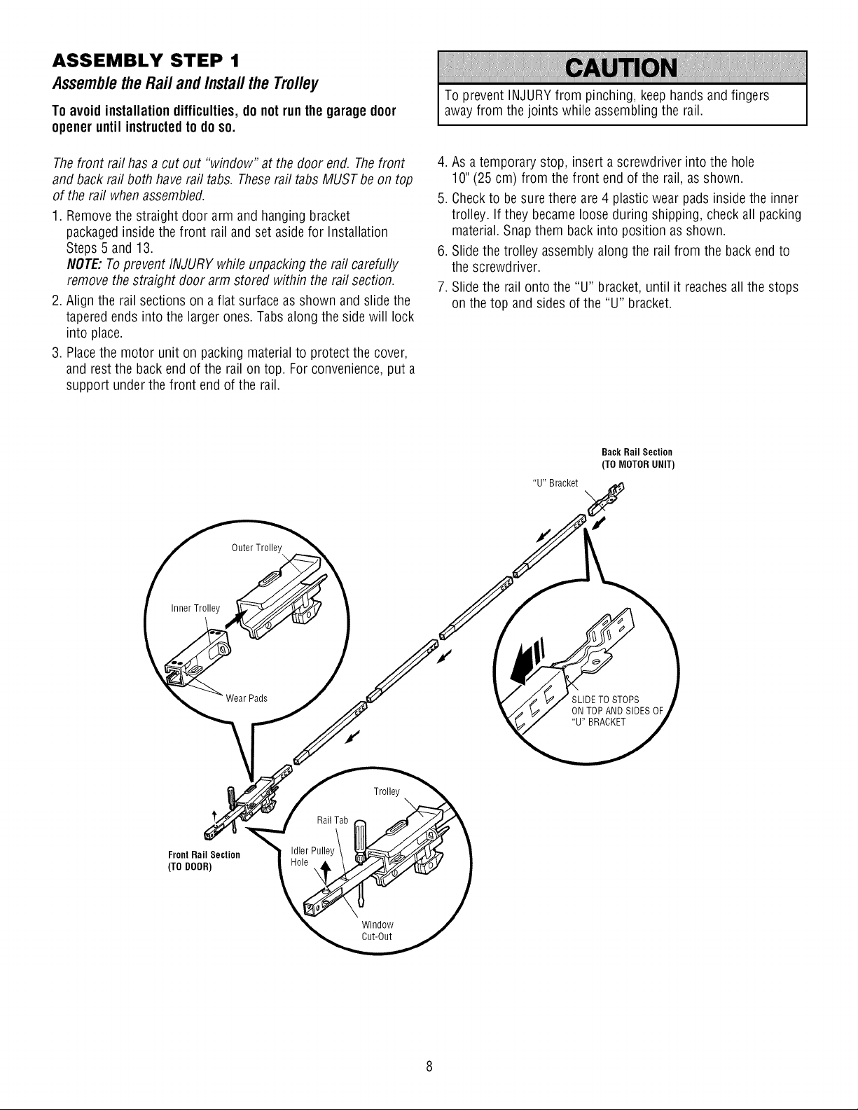
ASSEMBLY STEP 1
Assemble the Rail and Install the Trolley
To avoid installation difficulties, do not run the garage door
openeruntil instructedto do so.
The front rail has a cut out "window" at the door end. The front
and back rail both have rail tabs. Theserail tabs MUST be on top
of the rail when assembled.
1. Removethe straight door arm and hanging bracket
packagedinside the front rail and set aside for Installation
Steps 5 and 13.
NOTE:To prevent INJURY while unpacking the rail carefully
remove the straight door arm stored within the rail section.
2. Align the rail sections on a flat surface as shown and slide the
tapered ends into the larger ones. Tabs along the side will lock
into place.
3. Placethe motor unit on packing material to protect the cover,
and rest the back end of the rail on top. For convenience,put a
support under the front end of the rail.
To prevent INJURY from pinching, keep hands and fingers
away from the joints while assembling the rail.
4. As a temporary stop, insert a screwdriver into the hole
10" (25 cm) from the front end of the rail, as shown.
5. Checkto besure there are 4 plastic wear pads inside the inner
trolley. If they becameloose during shipping, check all packing
material. Snapthem back into position as shown.
6. Slide the trolley assembly along the rail from the back end to
the screwdriver.
7. Slide the rail onto the "U" bracket, until it reachesall the stops
on the top and sides of the "U" bracket.
Back Rail Section
(TO MOTOR UNIT)
Outer Trolley
InnerTrolley
Wear Pads
SLIDETO STOPS
ON TOP AND SIDES OF
"U" BRACKET
FrontRail Section
(TO DOOR)
Rail Tab
Idler Pulley
Trolley
Window
Cut-Out
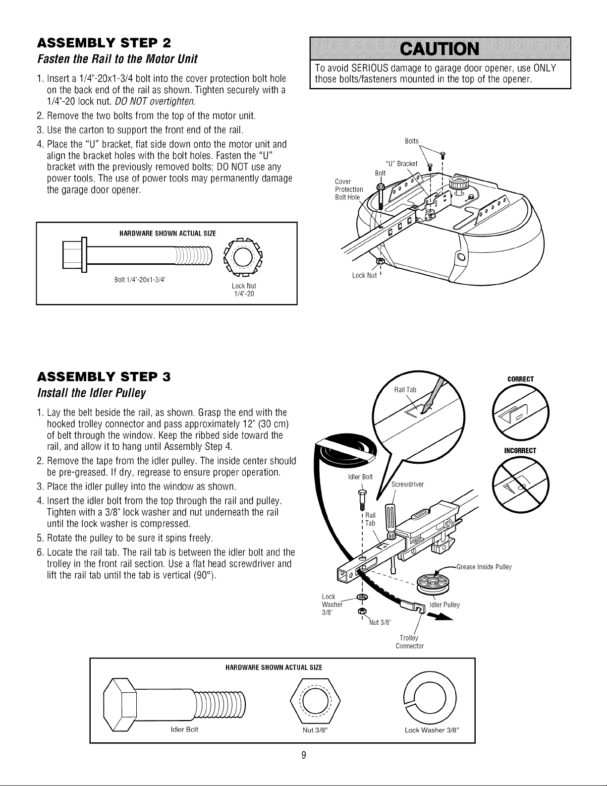
ASSEMBLY STEP 2
Fastenthe Rai/ to the Motor Unit
1. Insert a 1/4"-20xl-3/4 bolt into the cover protection bolt hole
on the back end of the rail as shown. Tighten securely with a
1/4"-20 lock nut. DO NOTovertighten.
2. Removethe two bolts from the top of the motor unit.
3. Usethe carton to support the front end of the rail.
4. Placethe "U" bracket, flat side down onto the motor unit and
align the bracket holes with the bolt holes. Fastenthe "U"
bracket with the previously removed bolts; DONOT use any
power tools. The use of power tools may permanently damage
the garagedoor opener.
To avoid SERIOUSdamageto garage door opener, use ONLY
those bolts/fasteners mounted in the top of the opener.
Bolts
Cover
Protection
Bolt Hole
"U" Bracket
Bolt \
HARDWARESHOWN ACTUALSIZE
d 0
Bolt 1/4"-20xl-3/4"
Lock Nut
1/4"-20
Lock Nut _
ASSEMBLY STEP 3
Insta// the Id/er Pu//ey
1. Laythe belt beside the rail, as shown. Graspthe end with the
hooked trolley connector and pass approximately 12" (30 cm)
of belt through the window. Keepthe ribbed side toward the
rail, and allow it to hang until Assembly Step 4.
2. Removethe tape from the idler pulley. The inside center should
be pre-greased. If dry, regreaseto ensure proper operation.
3. Placethe idler pulley into the window as shown.
4. Insert the idler bolt from the top through the rail and pulley.
Tighten with a 3/8" lock washer and nut underneaththe rail
until the lock washer is compressed.
5. Rotatethe pulley to be sure it spins freely.
6. Locatethe rail tab. The rail tab is betweenthe idler bolt and the
trolley in the front rail section. Usea flat headscrewdriver and
lift the rail tab until the tab is vertical (90°).
Screwdriver
. _ _Grease Inside
I
Lock _
Washer _ Idler Pulley
3/8" _l_Nut 3/8"
Trolley
Connector
HARDWARESHOWN ACTUALSIZE
Idler Bolt Nut 3/8"
Lock Washer 3/8"
CORRECT
Q
INCORRECT
Pulley
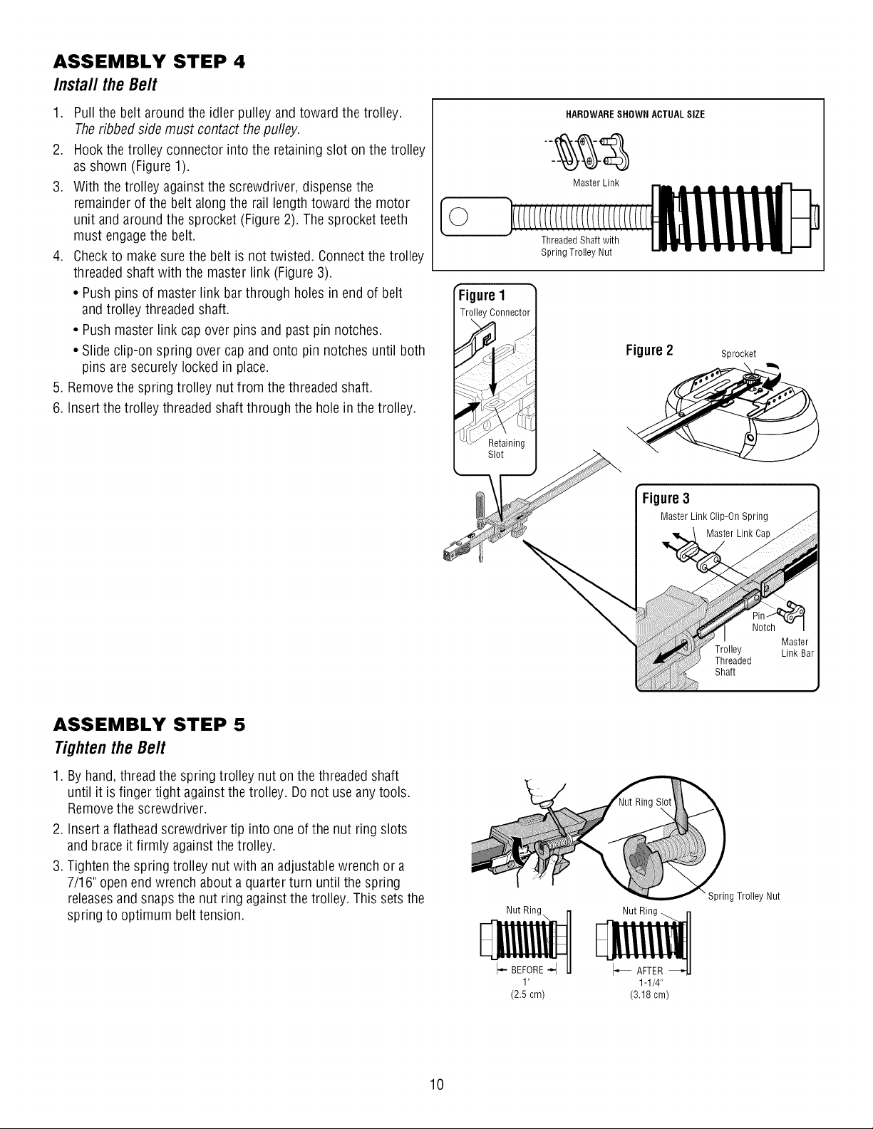
ASSEMBLY STEP 4
Install the Belt
1. Pull the belt around the idler pulley and toward the trolley.
Theribbed side must contact the pufley.
2. Hookthe trolley connector into the retaining slot on the trolley
as shown (Figure 1).
3. With the trolley against the screwdriver, dispensethe
remainder of the belt along the rail length toward the motor
unit and around the sprocket (Figure 2). The sprocket teeth
must engagethe belt.
4. Checkto make sure the belt is not twisted. Connect the trolley
threaded shaft with the master link (Figure 3).
• Push pins of master link bar through holes in end of belt
and trolley threaded shaft.
• Push master link cap over pins and past pin notches.
• Slide clip-on spring over cap and onto pin notches until both
pins are securely locked in place.
5. Removethe spring trolley nut from the threaded shaft.
6. Insert the trolley threaded shaft through the holein the trolley.
[©
HARDWARESHOWN ACTUALSIZE
Master Link
FTigureI 1
rolley Connector]
Threaded Shaft with
Spring Trolley Nut
Figure2
Sprocket
Figure3
Master Link Clip-On Spring
Master Link Cap
ASSEMBLY STEP 5
Tightenthe Belt
1. By hand, thread the spring trolley nut on the threaded shaft
until it is finger tight against the trolley. Do not use any tools.
Removethe screwdriver.
2. Insert a flathead screwdriver tip into oneof the nut ring slots
and brace it firmly againstthe trolley.
3. Tighten the spring trolley nut with an adjustable wrench or a
7/16" open end wrench about a quarter turn until the spring
releasesand snapsthe nut ring againstthe trolley. This sets the
spring to optimum belt tension.
I- BEFORE-I
1 "
(2.5 cm)
1-1/4"
(3.18 cm)
" Spring Trolley Nut
10
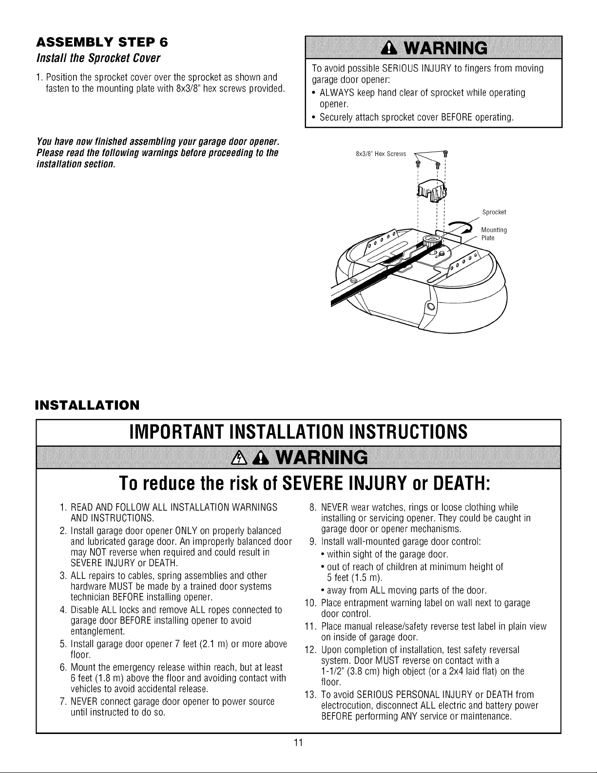
ASSEMBLY STEP 6
Install the SprocketCover
1. Position the sprocket cover over the sprocket as shown and
fasten to the mounting plate with 8x3/8" hex screws provided.
Youhave nowfinishedassemb//ngyour garage door opener.
P/ease read the lot/owing warningsbeforeproceedingto the
insta//afion section.
To avoid possible SERIOUSINJURYto fingers from moving
garagedoor opener:
• ALWAYS keep hand clear of sprocket while operating
opener.
• Securely attach sprocket cover BEFOREoperating.
8x3/8" Hex Screws
Sprocket
Mounting
Plate
INSTALLATION
IMPORTANTINSTALLATIONINSTRUCTIONS
To reducethe riskof SEVEREINJURYor DEATH:
1. READAND FOLLOWALL INSTALLATIONWARNINGS
AND INSTRUCTIONS.
2. Install garage door opener ONLYon properly balanced
and lubricated garage door. An improperly balanced door
may NOT reverse when required and could result in
SEVEREINJURYor DEATH.
3. ALL repairs to cables, spring assemblies and other
hardware MUST be made by a trained door systems
technician BEFOREinstalling opener.
4. Disable ALL locks and remove ALL ropes connected to
garage door BEFOREinstalling opener to avoid
entanglement.
5. Install garage door opener 7 feet (2.1 m) or more above
floor.
6. Mount the emergency releasewithin reach, but at least
6 feet (1.8 m) above the floor and avoiding contact with
vehicles to avoid accidental release.
7. NEVERconnect garagedoor opener to power source
until instructed to do so.
8. NEVERwear watches, rings or loose clothing while
installing or servicing opener. They could be caught in
garagedoor or opener mechanisms.
9. Install wall-mounted garage door control:
• within sight of the garage door.
• out of reachof children at minimum height of
5 feet (1.5 m).
• away from ALL moving parts of the door.
10. Place entrapment warning label on wall next to garage
door control.
11. Placemanual release/safetyreverse test label in plain view
on inside of garage door.
12. Upon completion of installation, test safety reversal
system. Door MUST reverse on contact with a
1-1/2" (3.8 cm) high object (or a 2x4 laid flat) on the
floor.
13. To avoid SERIOUSPERSONALINJURYor DEATHfrom
electrocution, disconnect ALL electric and battery power
BEFOREperforming ANY service or maintenance.
11
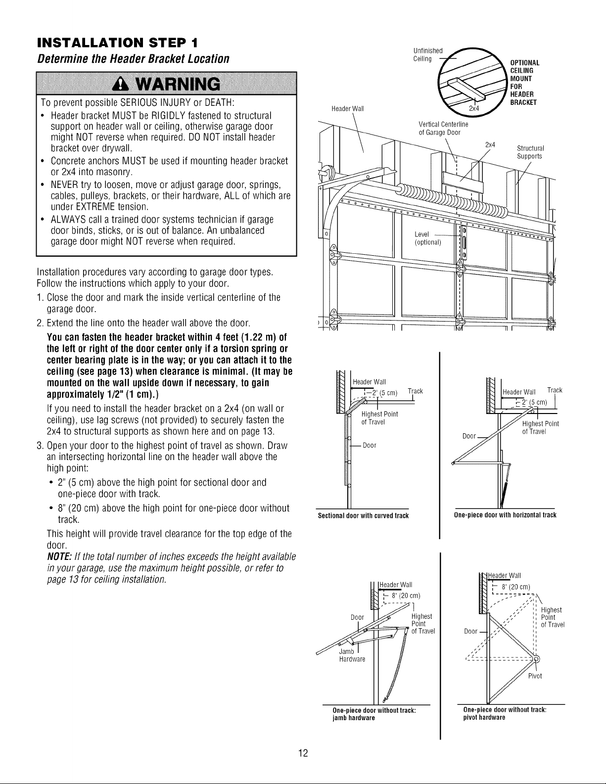
INSTALLATION STEP 1
Determinethe HeaderBracketLocation
To prevent possible SERIOUSINJURYor DEATH:
• Headerbracket MUST be RIGIDLY fastened to structural
support on headerwall or ceiling, otherwise garagedoor
might NOTreversewhen required. DONOTinstall header
bracket over drywall.
• Concrete anchors MUST be used if mounting headerbracket
or 2x4 into masonry.
• NEVERtry to loosen, move or adjust garagedoor, springs,
cables, pulleys, brackets, or their hardware,ALL of which are
under EXTREMEtension.
• ALWAYScall a trained door systems technician if garage
door binds, sticks, or is out of balance.An unbalanced
garagedoor might NOT reverse when required.
Installation procedures vary according to garagedoor types.
Follow the instructions which apply to your door.
1. Closethe door and mark the inside vertical centerline of the
garagedoor.
2. Extendthe line onto the header wall above the door.
Youcan fasten the header bracketwithin 4 feet (1.22 m) of
the left or rightof the door center only if a torsion springor
center bearingplate is in the way; or you can attach it to the
ceiling (see page 13) when clearance is minimal. (It may be
mountedon the wall upsidedown if necessary,to gain
approximately1/2" (1 cm).)
If you needto install the headerbracket on a 2x4 (on wall or
ceiling), use lag screws (not provided) to securely fasten the
2x4 to structural supports as shown hereand on page 13.
3. Openyour door to the highest point of travel as shown. Draw
an intersecting horizontal line on the header wall above the
high point:
• 2" (5 cm) above the high point for sectional door and
one-piece door with track.
• 8" (20 cm) above the high point for one-piece door without
track.
This height will provide travel clearancefor the top edge of the
door.
NOTE:If the total number of inches exceedsthe height available
in your garage, use the maximum height possible, or refer to
page 13 for ceiling installation.
Unfinished
Ceiling
HeaderWall
Vertical Centerline
of Garage Door
Header Wall
Track
Highest Point
of Travel
Door
Sectional door with curvedtrack
all
_Highest
Hardware
One-piecedoor withouttrack:
jambhardware
OPTIONAL
CEILING
MOUNT
!FOR
HEADER
BRACKET
2x4 Structural
Supports
Y
e"
HeaderWall Track
t
One-piece door with horizontal track
Header Wall
:- 8" (20 cm)
" -;" ", Highest
I_#..-;" ,', Point
41-:-_'_/I."_-" ',',of Travel
Door ',
One-piece door without track:
pivot hardware
12
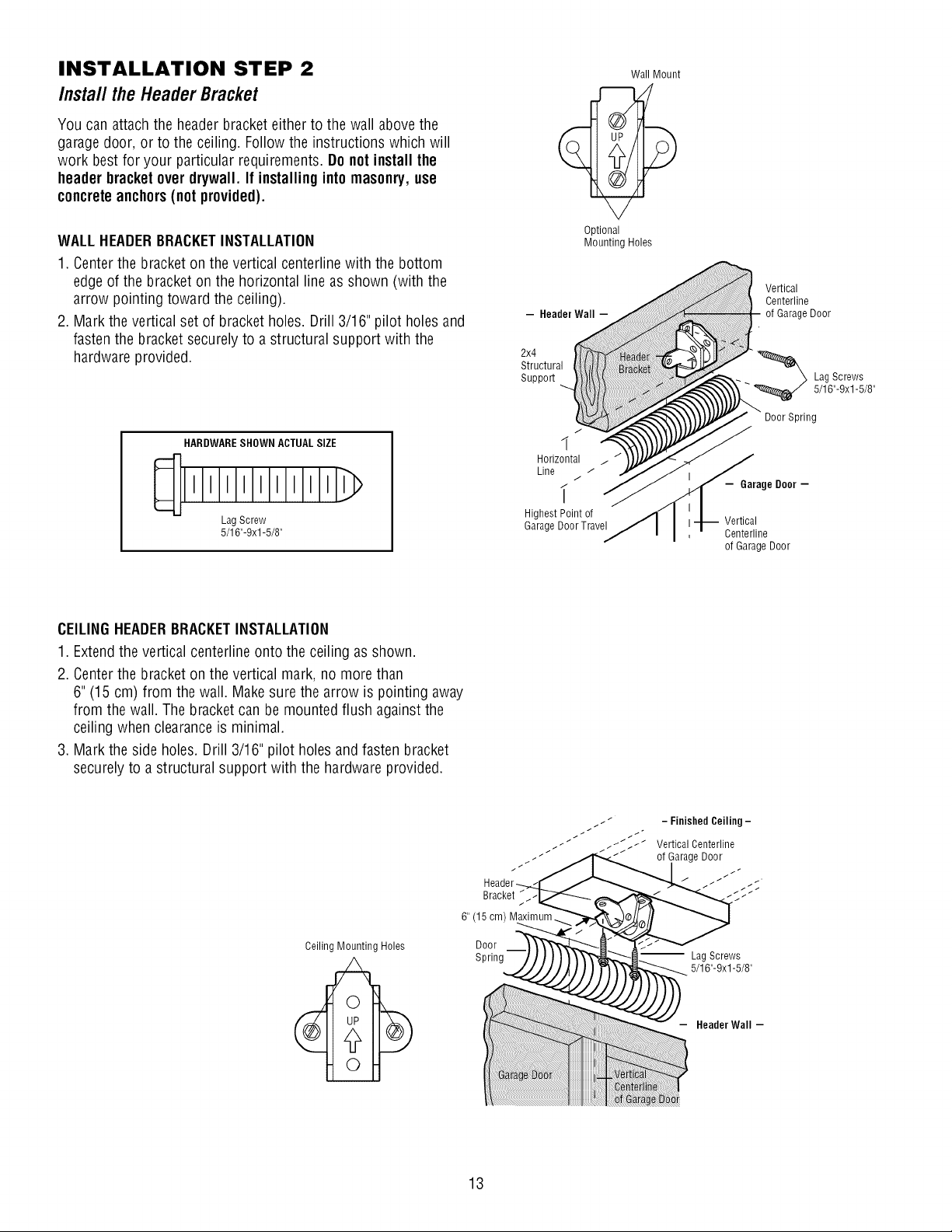
INSTALLATION STEP 2
Install the Header Bracket
You can attach the header bracket either to the wall above the
garagedoor, or to the ceiling. Follow the instructions which will
work bestfor your particular requirements. Do not install the
header bracket over drywall. If installing into masonry,use
concreteanchors(not provided).
WALLHEADERBRACKETINSTALLATION
1. Centerthe bracket on the vertical centerline with the bottom
edge of the bracket on the horizontal line as shown (with the
arrow pointing toward the ceiling).
2. Mark the vertical set of bracket holes. Drill 3/16" pilot holes and
fasten the bracket securely to a structural support with the
hardware provided.
HARDWARESHOWN ACTUALSIZE
LagScrew
5/16"-9xl -5/8"
- Header Wall -
2x4
Structural
SuppoR
J
1
Horizontal
Line
i
Highest Point of
GarageDoorTravel
Wall Mount
Optional
Mounting Holes
Vertical
Centerline
of Garage Door
_ Lag Screws
5/16"-9xl -5/8"
Door Spring
- Garage Door -
Vertical
Centerline
of Garage Door
CEILINGHEADERBRACKETINSTALLATION
1. Extendthe vertical centerline onto the ceiling as shown.
2. Centerthe bracket on the vertical mark, no more than
6" (15 cm) from the wall. Make sure the arrow is pointing away
from the wall. The bracket can be mounted flush against the
ceiling when clearanceis minimal.
3. Mark the side holes. Drill 3/16" pilot holes and fasten bracket
securely to a structural support with the hardware provided.
Ceiling Mounting Holes
Bracket
6" (15 cm) M
- FinishedCeiling-
VerticalCenterline
of GarageDoor
Door
Spring
" Lag Screws
5/16"-9xl -5/8"
HeaderWall -
13
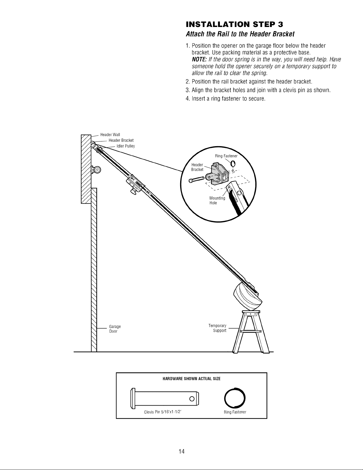
INSTALLATION STEP 3
Attachthe Rail to the HeaderBracket
1. Position the opener on the garage floor below the header
bracket. Use packing material as a protective base.
NOTE:If the door spring is in the way, you will need help. Have
someone hold the opener securely on a temporary support to
allow the rail to clear the spring.
2. Position the rail bracket against the headerbracket.
3. Align the bracket holes and join with a clevis pin as shown.
4. Insert a ring fastener to secure.
Header Wall
Header Bracket
Idler Pulley
"o
Mounting
Hole
__ Garage
Door
Temporary
Support
HARDWARESHOWN ACTUALSIZE
0
Clevis Pin 5/16"x1-1/2" Ring Fastener
14
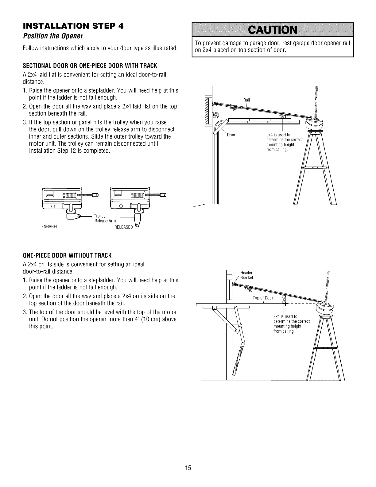
INSTALLATION STEP 4
Positionthe Opener
Follow instructions which apply to your door type as illustrated.
SECTIONALDOOROR ONE-PIECEDOORWITH TRACK
A 2x4 laid flat is convenient for setting an ideal door-to-rail
distance.
1. Raisethe opener onto a stepladder. You will need help at this
point if the ladder is not tall enough.
2. Openthe door all the way and place a 2x4 laid flat on the top
section beneath the rail.
3. If the top section or panel hits the trolley when you raise
the door, pull down on the trolley releasearm to disconnect
inner and outer sections. Slide the outer trolley toward the
motor unit. The trolley can remain disconnected until
Installation Step 12 is completed.
To prevent damage to garage door, rest garage door opener rail
on 2x4 placed on top section of door.
Rail
Door 2x4 is used to
Trolley
lease
ENGAGED RELEASED _
ONE-PIECEDOORWITHOUTTRACK
A 2x4 on its side is convenient for setting an ideal
door-to-rail distance.
1. Raisethe opener onto a stepladder. You will need help at this
point if the ladder is not tall enough.
2. Openthe door all the way and place a 2x4 on its side on the
top section of the door beneath the rail.
3. The top of the door should be level with the top of the motor
unit. Do not position the opener more than 4" (10 cm) above
this point.
Header
Bracket
I
from ceiling.
2x4 is used to
determine the correct
mounting height
from ceiling.
15
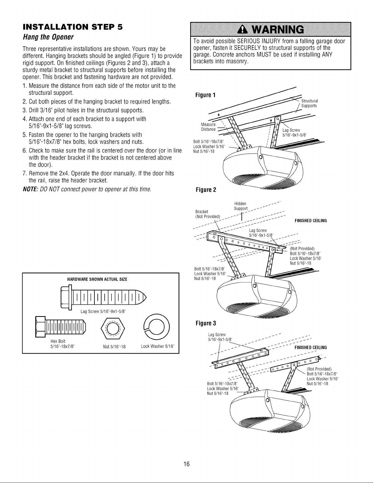
INSTALLATION STEP 5
Hang the Opener
Three representative installations are shown. Yours may be
different. Hanging brackets should be angled (Figure 1) to provide
rigid support. On finished ceilings (Figures 2 and 3), attach a
sturdy metal bracket to structural supports before installing the
opener. This bracket and fastening hardware are not provided.
1. Measurethe distance from each side of the motor unit to the
structural support.
2. Cut both piecesof the hanging bracket to required lengths.
3. Drill 3/16" pilot holes in the structural supports.
4. Attach one end of each bracket to a support with
5/16"-9xl-5/8" lag screws.
5. Fastenthe opener to the hanging brackets with
5/16"-18x7/8" hex bolts, lock washers and nuts.
6. Checkto make sure the rail is centered over the door (or in line
with the header bracket if the bracket is not centeredabove
the door).
7. Removethe 2x4. Operatethe door manually. If the door hits
the rail, raise the header bracket.
NOTE:DO NOT connect power to openerat this time.
HARDWARESHOWN ACTUALSIZE
llllllllllll
LagScrew5/16"-9xl-5/8"
HexBolt
5/16"-18x7/8" Nut 5/16"-18 Lock Washer5/16"
To avoid possible SERIOUSINJURYfrom a falling garage door
opener, fasten it SECURELYto structural supports of the
garage. Concrete anchors MUST be used if installing ANY
brackets into masonry.
FigureI
)orts
Measure ',
Distance
Bolt 5/16"-18x7/8"
Lock Washer 5/16"
Nut 5/16"-18
Lag Screw
5/16"-9xl -5/8"
Figure2
Hidden _- _ _ _
Bracket Support _ _- _
(Not Provided) _ _ _ _ 1 _ _ _
_ . _,,,,,._&_-- _ _- _ Lag Screw
-222_ ....
_\k __(Not Provided)
.- _ - _ _ ._7_--- - L/_r .-,_ Bolt5/16"-18x7/8"
- --- _.\o,_o__.-- LH Lock Washer 5/16"
- _,_.X _/_ Nut 5/16"-18
Figure3
Lag Screw
5/16"-9xl -5/8"
Bolt 5/16"-18x7/8"
LockWasher5/16"
Nut 5/16"-18
FINISHED CEILING
(Not Provided)
Bolt 5/16"-18x7/8"
Lock Washer 5/16"
Nut 5/16"-18
16
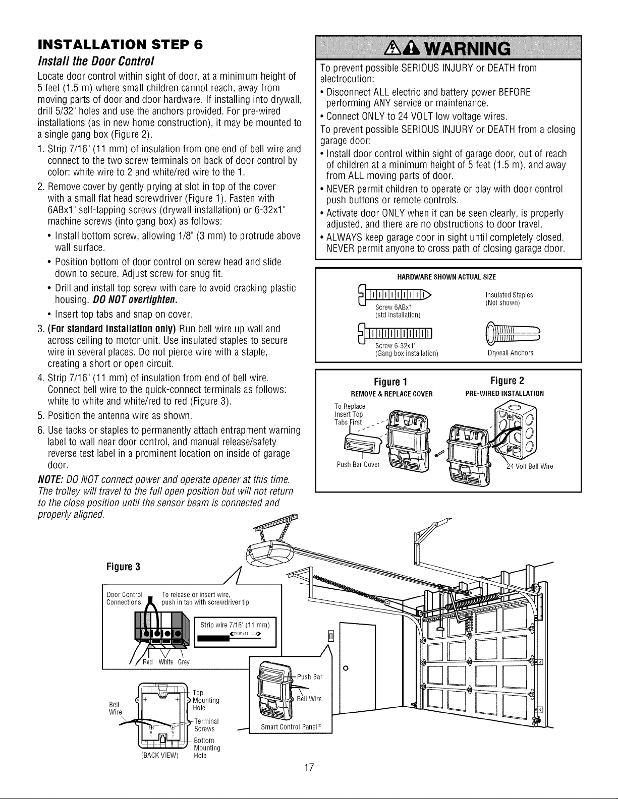
INSTALLATION STEP 6
Install the Door Control
Locate door control within sight of door, at a minimum height of
5 feet (1.5 m) where small children cannot reach, away from
moving parts of door and door hardware. If installing into drywall,
drill 5/32" holes and use the anchors provided. For pro-wired
installations (as in new home construction), it may be mounted to
a single gang box (Figure 2).
1. Strip 7/16" (11 mm) of insulation from one end of bell wire and
connect to the two screw terminals on back of door control by
color: white wire to 2 and white/red wire to the 1.
2. Removecover by gently prying at slot in top of the cover
with a small flat headscrewdriver (Figure 1). Fastenwith
6ABxl" self-tapping screws (drywall installation) or 6-32x1"
machine screws (into gang box) as follows:
• Install bottom screw, allowing 1/8" (3 mm) to protrude above
wall surface.
• Position bottom of door control on screw head and slide
down to secure. Adjust screw for snug fit.
• Drill and install top screw with care to avoid cracking plastic
housing. DO NOT overtighten.
• Insert top tabs and snap on cover.
3. (For standard installation only) Run bell wire up wall and
across ceiling to motor unit. Use insulated staples to secure
wire in several places. Do not pierce wire with a staple,
creating a short or open circuit.
4. Strip 7/16" (11 mm) of insulation from end of bell wire.
Connect bell wire to the quick-connect terminals as follows:
white to white and white/red to red (Figure 3).
5. Position the antenna wire as shown.
6. Usetacks or staples to permanently attach entrapment warning
label to wall near door control, and manual release/safety
reversetest label in a prominent location on inside of garage
door.
NOTE:DO NOT connect power and operate opener at this time.
The trolley will travel to the furl open position but will not return
to the close position until the sensor beam is connected and
properly aligned.
To prevent possible SERIOUSINJURYor DEATHfrom
electrocution:
• DisconnectALL electric and battery power BEFORE
performing ANY service or maintenance.
• Connect ONLYto 24 VOLT low voltage wires.
To prevent possible SERIOUSINJURYor DEATHfrom a closing
garagedoor:
• Install door control within sight of garagedoor, out of reach
of children at a minimum height of 5 feet (1.5 m), and away
from ALL moving parts of door.
• NEVERpermit children to operate or play with door control
push buttons or remote controls.
• Activate door ONLYwhen it can be seen clearly, is properly
adjusted, and there are no obstructions to door travel.
• ALWAYS keep garage door in sight until completely closed.
NEVERpermit anyone to cross path of closing garagedoor.
HARDWARESHOWN ACTUALSIZE
_ lllllllllMIMlllllb Insulated Staples
Screw 6ABxl" (Not shown)
(std installation)
(Gang box installation) Drywall Anchors
Figure I Figure2
REMOVE & REPLACECOVER PRE-WIREDINSTALLATION
To Replace
Insert Top
Tab___ _ _'"
Push Bar Cover I Wire
Figure 3 ,___
Door Control To release or insert wire,
Connections )ush in tab with screwdriver tip
Strip wire 7/16" (11 mm)
417/1611 (11 m m)]D.
Red White Grey
_ ,, _1+ -- +1 )Mounting
_ell II I I Hole
Wire It I_1'
_=_Terminal
II T-, TI I screws
It:__ Bottom
" " Mounting
(BACKVIEW) Hole
A
F Push Bar
_Wi re
Smart Control PaneP
17
0
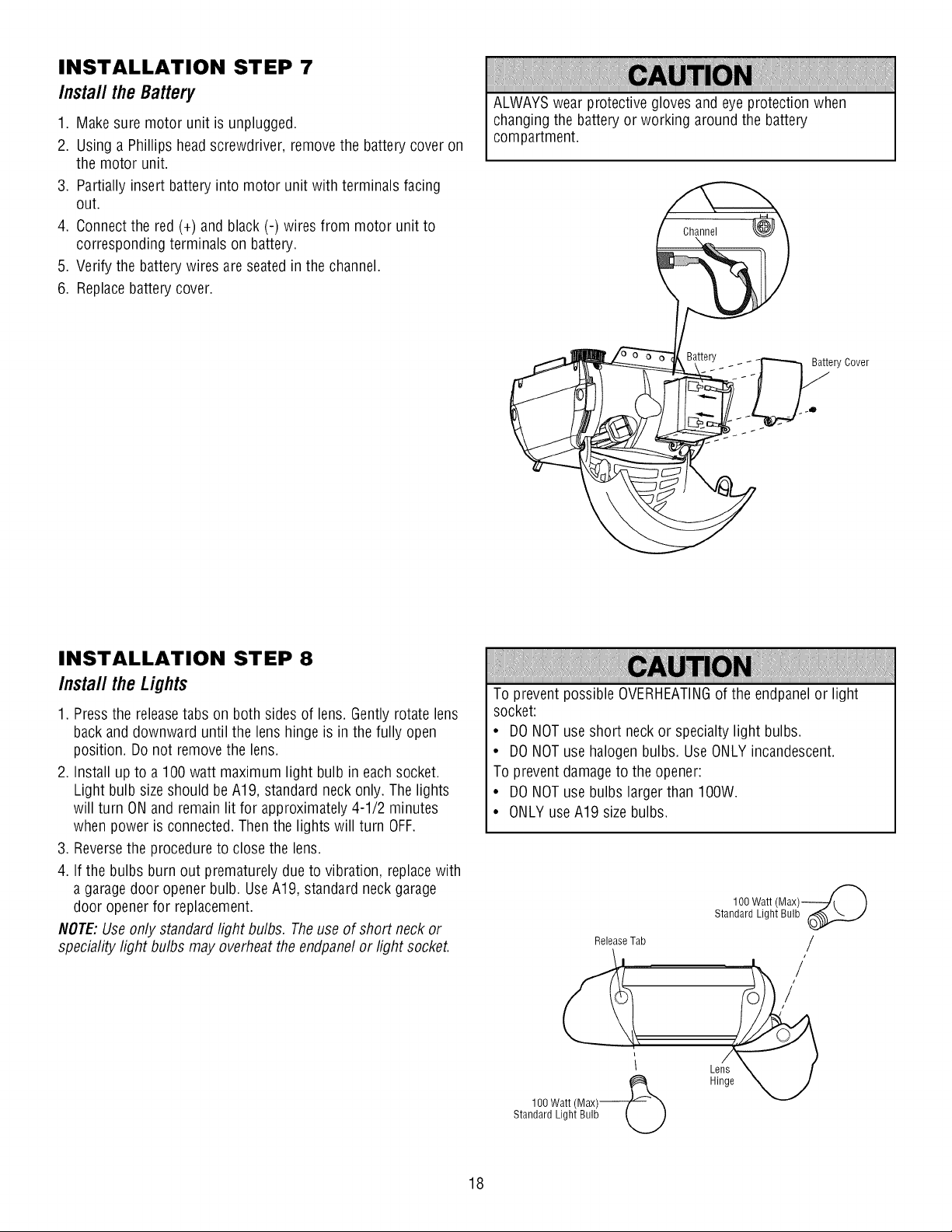
INSTALLATION STEP 7
Install the Battery
1. Make sure motor unit is unplugged.
2. Using a Phillips head screwdriver, remove the battery cover on
the motor unit.
3. Partially insert battery into motor unit with terminals facing
out.
4. Connect the red (+) and black (-) wires from motor unit to
corresponding terminals on battery.
5. Verify the battery wires are seated in the channel.
6. Replace battery cover.
ALWAYSwear protective gloves and eye protection when
changing the battery or working around the battery
compartment.
Battery
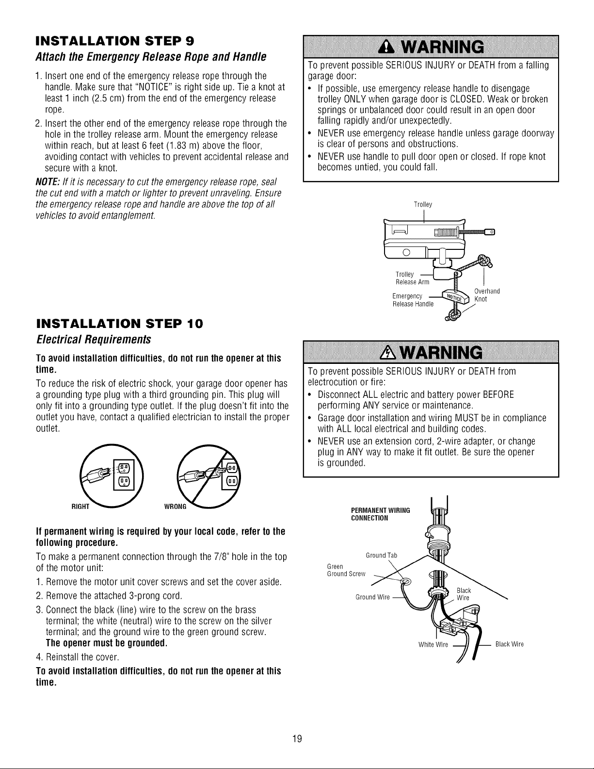
INSTALLATION STEP 8
Install the Lights
1. Pressthe releasetabs on both sides of lens. Gently rotate lens
back and downward until the lens hinge is in the fully open
position. Do not remove the lens.
2. Install up to a 100 watt maximum light bulb in each socket.
Light bulb size should be A19, standard neck only. The lights
will turn ON and remain lit for approximately 4-1/2 minutes
when power is connected.Then the lights will turn OFF.
3. Reversethe procedure to close the lens.
4. If the bulbs burn out prematurely due to vibration, replace with
a garage door opener bulb. UseA19, standard neck garage
door opener for replacement.
NOTE:Useonly standard light bulbs. The use of short neck or
speciality light bulbs may overheatthe endpanel or light socket.
To prevent possible OVERHEATINGof the endpanelor light
socket:
• DONOT use short neck or specialty light bulbs.
• DONOT use halogen bulbs. UseONLY incandescent.
To prevent damage to the opener:
• DONOT use bulbs larger than IOOW.
• ONLY use A19 size bulbs.
1O0 Watt
Standard Light Bulb
Release Tab /
Hinge
100 Watt (Max)_
Standard Light Bulb _...._
18
INSTALLATION STEP 9
Attachthe EmergencyRelease Ropeand Handle
1. Insert one end of the emergency release rope through the
handle. Makesure that "NOTICE"is right side up. Tie a knot at
least 1 inch (2.5 cm) from the end of the emergency release
rope.
2. Insert the other end of the emergency releaserope through the
hole in the trolley releasearm. Mount the emergency release
within reach, but at least 6 feet (1.83 m) abovethe floor,
avoiding contact with vehicles to prevent accidental releaseand
secure with a knot.
NOTE:If it is necessary to cut the emergency releaserope, seal
the cut end with a match or lighter to prevent unraveling. Ensure
the emergency releaserope and handle areabove the top of aft
vehicles to avoid entanglement.
INSTALLATION STEP 10
Electrical Requirements
To avoid installation difficulties, do not run the openerat this
time.
To reduce the risk of electric shock, your garagedoor opener has
a grounding type plug with a third grounding pin. This plug will
only fit into a grounding type outlet. If the plug doesn't fit into the
outlet you have, contact a qualified electrician to install the proper
outlet.
If permanent wiring is required by your local code, refer to the
following procedure.
To make a permanent connection through the 7/8" hole in the top
of the motor unit:
1. Removethe motor unit cover screws and set the cover aside.
2. Removethe attached 3-prong cord.
3. Connect the black (line) wire to the screw on the brass
terminal; the white (neutral) wire to the screw on the silver
terminal; and the ground wire to the green ground screw.
The openermust be grounded.
4. Reinstallthe cover.
To avoid installation difficulties, do not run the openerat this
time.
To prevent possible SERIOUSINJURYor DEATHfrom a falling
garagedoor:
• If possible, use emergency releasehandleto disengage
trolley ONLYwhen garagedoor is CLOSED.Weak or broken
springs or unbalanceddoor could result in an open door
falling rapidly and/or unexpectedly.
• NEVERuse emergency releasehandle unless garagedoorway
is clear of persons and obstructions.
• NEVERuse handle to pull door open or closed. If rope knot
becomes untied, you could fall.
Trolley
I
__e Arlm_ _
Emergency _ _verhandnot
Release Handle
To prevent possible SERIOUSINJURYor DEATHfrom
electrocution or fire:
• DisconnectALL electric and battery power BEFORE
performing ANY service or maintenance.
• Garagedoor installation and wiring MUST be in compliance
with ALL local electrical and building codes.
• NEVERuse an extension cord, 2-wire adapter,or change
plug in ANY way to make it fit outlet. Besure the opener
is grounded.
PERMANENTWIRING
CONNECTION
Ground Tab
Green
Ground Screw
Ground Wire Wire
White Wire Black Wire
19
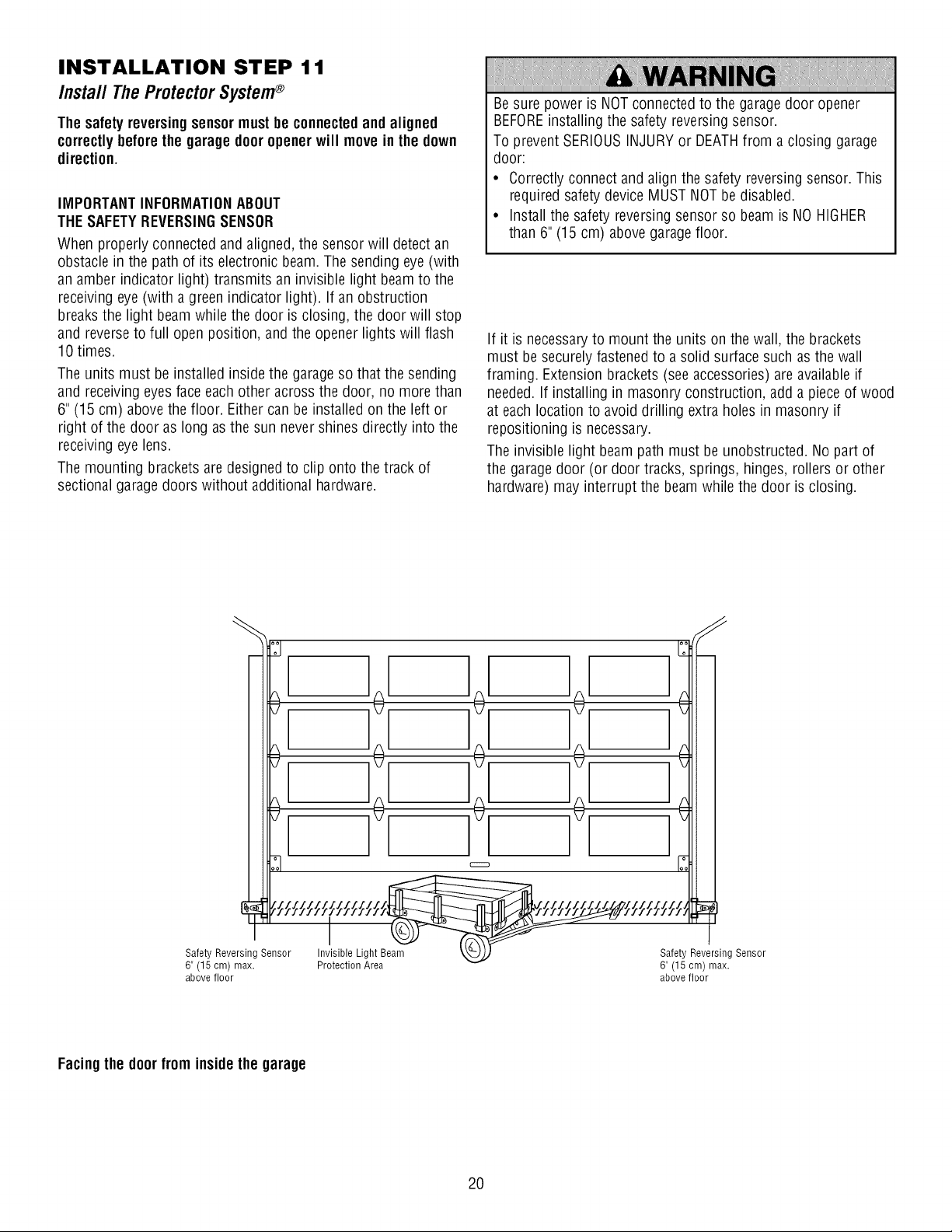
INSTALLATION STEP 11
Install The ProtectorSystem®
Thesafety reversingsensormust be connectedand aligned
correctlybefore the garage door opener will move in the down
direction.
IMPORTANTINFORMATIONABOUT
THESAFETYREVERSINGSENSOR
When properly connected and aligned, the sensor will detect an
obstacle in the path of its electronic beam. The sending eye (with
an amber indicator light) transmits an invisible light beam to the
receiving eye (with a green indicator light). If an obstruction
breaks the light beam while the door is closing, the door will stop
and reverse to full open position, and the opener lights will flash
10 times.
The units must be installed inside the garageso that the sending
and receiving eyes face each other across the door, no more than
6" (15 cm) above the floor. Either can be installed on the left or
right of the door as long as the sun never shines directly into the
receiving eye lens.
The mounting brackets are designed to clip onto the track of
sectional garagedoors without additional hardware.
Besure power is NOTconnected to the garagedoor opener
BEFOREinstalling the safety reversing sensor.
To prevent SERIOUSINJURY or DEATHfrom a closing garage
door:
• Correctly connect and align the safety reversingsensor. This
required safety device MUST NOT be disabled.
• Install the safety reversing sensor so beam is NO HIGHER
than 6" (15 cm) above garage floor.
If it is necessaryto mount the units on the wall, the brackets
must be securely fastened to a solid surface such as the wall
framing. Extension brackets (see accessories) areavailable if
needed. If installing in masonry construction, add a piece of wood
at each location to avoid drilling extra holes in masonry if
repositioning is necessary.
The invisible light beam path must be unobstructed. No part of
the garagedoor (or door tracks, springs, hinges, rollers or other
hardware) may interrupt the beam while the door is closing.
Reversing Sensor Invisible Light B_,,, _,_.._ Safety R, versing Sensor
6" (15 cm) max. Protection Area 6" (15 cm) max.
above floor above floor
Facingthe doorfrom inside the garage
2O
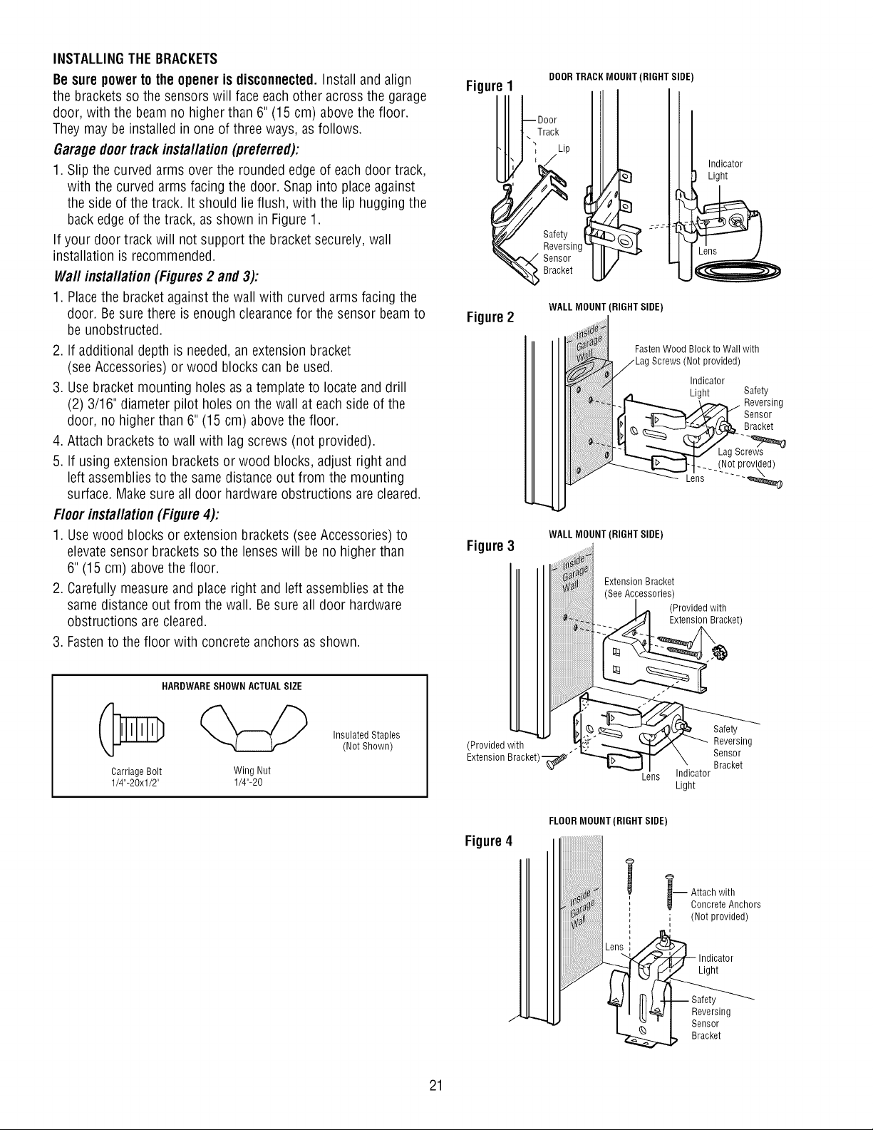
INSTALLINGTHE BRACKETS
Be sure power to the opener is disconnected. Install and align
the brackets so the sensors will face each other across the garage
door, with the beam no higher than 6" (15 cm) above the floor.
They may be installed in one of three ways, as follows.
Garage doortrack installation (preferred):
1. Slip the curved arms over the rounded edge of each door track,
with the curved arms facing the door. Snap into place against
the side of the track. It should lie flush, with the lip hugging the
back edge of the track, as shown in Figure 1.
If your door track will not support the bracket securely,wall
installation is recommended.
Wall installation (Figures2 and 3):
1. Placethe bracket against the wall with curved arms facing the
door. Besure there is enough clearancefor the sensor beam to
be unobstructed.
2. If additional depth is needed,an extension bracket
(see Accessories) or wood blocks can be used.
3. Usebracket mounting holes as a template to locate and drill
(2) 3/16" diameter pilot holes on the wall at eachside of the
door, no higher than 6" (15 cm) above the floor.
4. Attach brackets to wall with lag screws (not provided).
5. If using extension brackets or wood blocks, adjust right and
left assemblies to the same distance out from the mounting
surface. Make sure all door hardware obstructions are cleared.
Floor installation (Figure 4):
1. Usewood blocks or extension brackets (see Accessories) to
elevatesensor brackets so the lenses will be no higher than
6" (15 cm) abovethe floor.
2. Carefully measure and place right and left assemblies at the
same distance out from the wall. Besure all door hardware
obstructions are cleared.
3. Fastento the floor with concrete anchors as shown.
HARDWARESHOWN ACTUALSIZE
Carriage Bolt Wing Nut
1/4"-20xl/2" 1/4"-20
InsulatedStaples
(NotShown)
DOORTRACK MOUNT (RIGHT SIDE)
1
,oureoorI[
t\ Track
1I: Lip
_i __ Indicator
Safety "--"-:
_--_ . Reversing
_--_.,._'_" Sensor
"_ Bracket
Figure2
WALL MOUNT (RIGHT SIDE)
FastenWood Block to Wall with
Screws (Not provided)
Indicator
Light Safety
Reversing
Sensor
Bracket
Lag Screws
_ (Not provided)
Lens ......
WALL MOUNT (RIGHT SIDE)
Figure3 ..........
Extension Bracket
(See Accessories)
I .,,., (Provided with
l .._f_l Extensio_ Bracket)
(Provided with ._?" __ k,..Y_i,_ _'_ Reversing
Extension Bracket)_"_ _. Sensor
_ I " _racKe[
Lens Indicator
Light
Figure4
J
FLOORMOUNT (RIGHT SIDE)
-- ttach with
Concrete Anchors
i (Not provided)
Indicator
Light
Reversing
Sensor
Bracket
21
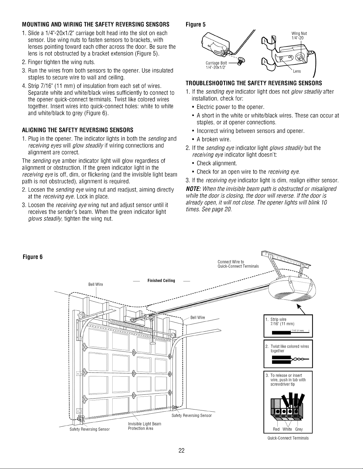
MOUNTINGANDWIRING THE SAFETYREVERSINGSENSORS
1. Slide a 1/4"-20xl/2" carriage bolt head into the slot on each
sensor. Usewing nuts to fasten sensors to brackets, with
lenses pointing toward each other across the door. Besure the
lens is not obstructed by a bracket extension (Figure 5).
2. Finger tighten the wing nuts.
3. Run the wires from both sensors to the opener. Use insulated
staples to secure wire to wall and ceiling.
4. Strip 7/16" (11 mm) of insulation from each set of wires.
Separatewhite and white/black wires sufficiently to connect to
the opener quick-connect terminals. Twist like colored wires
together. Insert wires into quick-connect holes: white to white
and white/black to grey (Figure 6).
ALIGNINGTHESAFETYREVERSINGSENSORS
1. Plug in the opener. The indicator lights in both the sending and
receiving eyeswill glow steadily if wiring connections and
alignment are correct.
The sending eye amber indicator light will glow regardless of
alignment or obstruction. If the green indicator light in the
receiving eye is off, dim, or flickering (and the invisible light beam
path is not obstructed), alignment is required.
2. Loosenthe sending eyewing nut and readjust, aiming directly
at the receiving eye. Lock in place.
3. Loosenthe receiving eyewing nut and adjust sensor until it
receivesthe sender's beam. When the green indicator light
glows steadily, tighten the wing nut.
Figure 5
Wing Nut
Carriage Bolt _
1/4"-20xl/2"
TROUBLESHOOTINGTHESAFETYREVERSINGSENSORS
1. If the sending eyeindicator light does not glow steadily after
installation, check for:
• Electric power to the opener.
• A short in the white or white/black wires. Thesecan occur at
staples, or at opener connections.
• Incorrect wiring between sensors and opener.
• A broken wire.
2. If the sending eye indicator light glows steadily but the
receiving eyeindicator light doesn't:
• Checkalignment.
• Checkfor an open wire to the receiving eye.
3. If the receiving eye indicator light is dim, realign either sensor.
NOTE:Whenthe invisible beam path is obstructed or misaligned
while the door is closing, the door will reverse. If the door is
already open, it will not close. Theopenerlights will blink 10
times. See page 20.
Figure 6
Bell Wire
Finished Ceiling
Connect Wire to
Quick-Connect Terminals
.... ,_ Bell Wire
\
1. Strip wire
7/16"(11mm)
7,16 (11 mm) I
2. Twist like colored wires
together
Safeb
Reversing Sensor
Invisible Light Beam
Protection Area
Safety Reversing Sensor
3. To release or insert
wire, push in tab with
screwdriver tip
Red White Grey
Quick-Connect Terminals
22
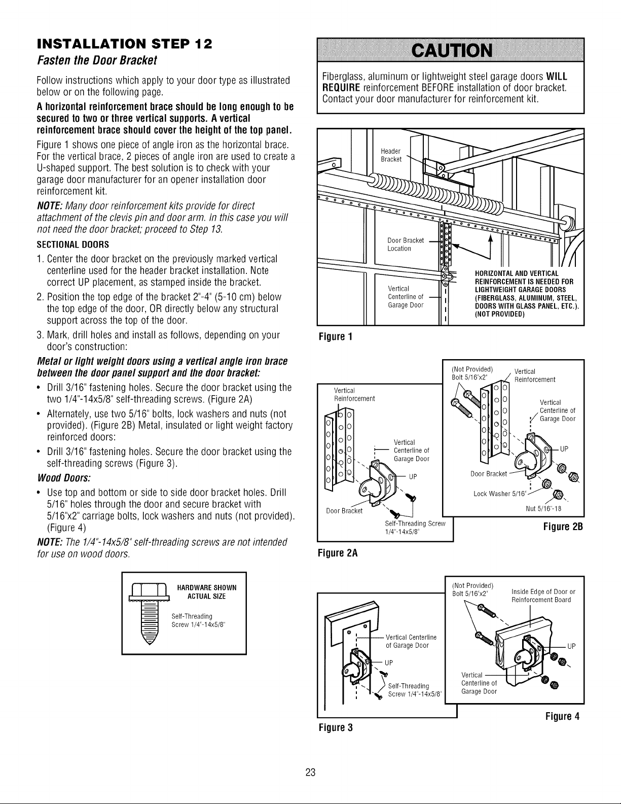
INSTALLATION STEP 12
Fastenthe DoorBracket
Follow instructions which apply to your door type as illustrated
below or on the following page.
A horizontal reinforcementbrace shouldbe long enoughto be
securedto two or three vertical supports.A vertical
reinforcementbraceshouldcover the height of the top panel.
Figure 1 shows one piece of angle iron as the horizontal brace.
For the vertical brace, 2 pieces of angle iron are used to createa
U-shaped support. The best solution is to check with your
garage door manufacturer for an opener installation door
reinforcement kit.
NOTE:Many door reinforcement kits provide for direct
attachment of the clevis pin and door arm. In this caseyou will
not needthe door bracket, proceed to Step 13.
SECTIONALDOORS
1. Centerthe door bracket on the previously marked vertical
centerline used for the headerbracket installation. Note
correct UP placement, as stamped inside the bracket.
2. Position the top edge of the bracket 2"-4" (5-10 cm) below
the top edgeof the door, OR directly below any structural
support across the top of the door.
3. Mark, drill holes and install as follows, depending on your
door's construction:
Metal orlight weight doorsusing a vertical angle iron brace
betweenthe doorpane/support and the door bracket:
• Drill 3/16" fastening holes. Secure the door bracket using the
two 1/4"-14x5/8" self-threading screws. (Figure 2A)
• Alternately, use two 5/16" bolts, lock washers and nuts (not
provided). (Figure 2B) Metal, insulated or light weight factory
reinforced doors:
• Drill 3/16" fastening holes. Secure the door bracket using the
self-threading screws (Figure 3).
WoodDoors:
• Usetop and bottom or side to side door bracket holes. Drill
5/16" holes through the door and secure bracket with
5/16"x2" carriage bolts, lock washers and nuts (not provided).
(Figure 4)
NOTE: The 1/4"-14x5/8" self-threading screws are not intended
for use on wood doors.
Fiberglass,aluminum or lightweight steel garage doors WILL
REQUIREreinforcement BEFOREinstallation of door bracket.
Contactyour door manufacturer for reinforcement kit.
Vertical
Centerline of
Garage Door
Figure 1
HORIZONTALAND VERTICAL
- REINFORCEMENTIS NEEDEDFOR
LIGHTWEIGHT GARAGEDOORS
(FIBERGLASS,ALUMINUM, STEEL,
DOORS WITH GLASS PANEL, ETC.).
(NOT PROVIDED)
Vertical
Reinforcement
O IG|U I _ Veernti_rallineof
ageDoor
Door Bracket
Self-Threading Screw
1/4"-14x5/8"
(Not Provided) Vertical
'x_ Reinforcement
r..d&"_1,_I1'_1_1 Vertical
"_'\I_ "¢/Ceanr_eg_ iDe°°°fr
.,_ UP
DoorBracket_ _t_
LockWasher 5/1B"_..
Nut 5/16"-18
Figure 2B
Figure 2A
HARDWARESHOWN
ACTUALSIZE
Self-Threading
Screw 1/4"-14x5/8"
Vertical Centerline
of Garage Door
_Self-Threading
"_1_, Screw 1/4"-14x5/8"
Figure3
(Not Provided)
Bolt 5/16"x2"
Inside Edge of Door or
Reinforcement Board
Centerline of _,
Garage Door
Figure4
23
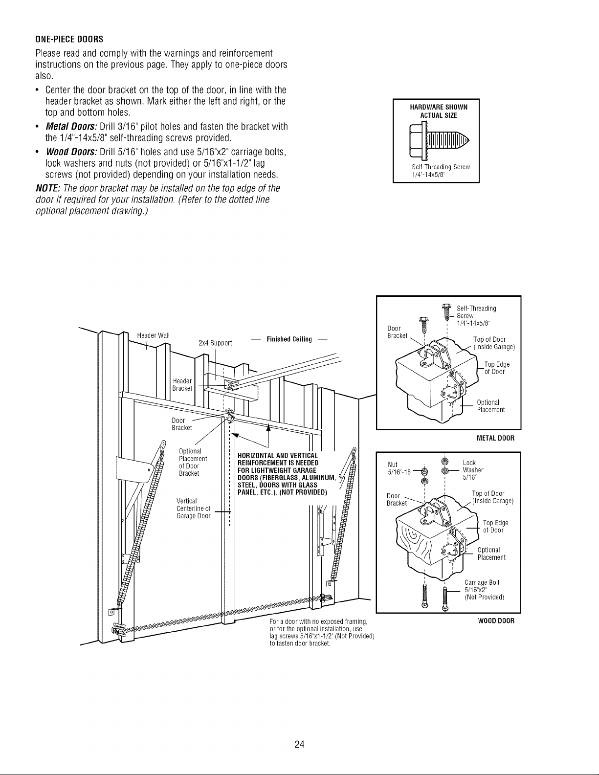
ONE-PIECEDOORS
Please read and comply with the warnings and reinforcement
instructions on the previous page. They apply to one-piece doors
also.
• Centerthe door bracket on the top of the door, in line with the
header bracket as shown. Mark either the left and right, or the
top and bottom holes.
• Metal Doors: Drill 3/16" pilot holes and fasten the bracket with
the 1/4"-14x5/8" self-threading screws provided.
• WoodDoors:Drill 5/16" holes and use 5/16"x2" carriage bolts,
lock washers and nuts (not provided) or 5/16"x1-1/2" lag
screws (not provided) depending on your installation needs.
NOTE:Thedoor bracket may be instafled on the top edge of the
door if required for your installation. (Refer to the dotted line
optional placement drawing.)
HARDWARESHOWN
ACTUALSIZE
Self-Threading Screw
1/4"-14x5/8"
Header Wall
Door
Bracket
2x4 Support
Optional
Placement
of Door
Bracket
Vertical
Centerline of
Garage Door
-- Finished Ceiling --
HORIZONTALAND VERTICAL
REINFORCEMENTIS NEEDED
FOR LIGHTWEIGHTGARAGE
DOORS(FIBERGLASS,ALUMINUM,
STEEL, DOORSWITH GLASS
PANEL, ETC.). (NOT PROVIDED)
For a door with no exposed framing,
or for the optional installation, use
lag screws 5/16"x1-1/2" (Not Provided)
to fasten door bracket.
Door
Bracket
__ elf-Threading
Screw
1/4"-14x5/8"
Top of Door
(Inside Garage)
Optional
Placement
METAL DOOR
Lock
@_ Washer
5/16"
Topof Door
Garage)
Top Edge
of Door
Optional
Placement
, Carriage Bolt
_ _-- 5/16"x2"
(Not Provided)
WOOD DOOR
24
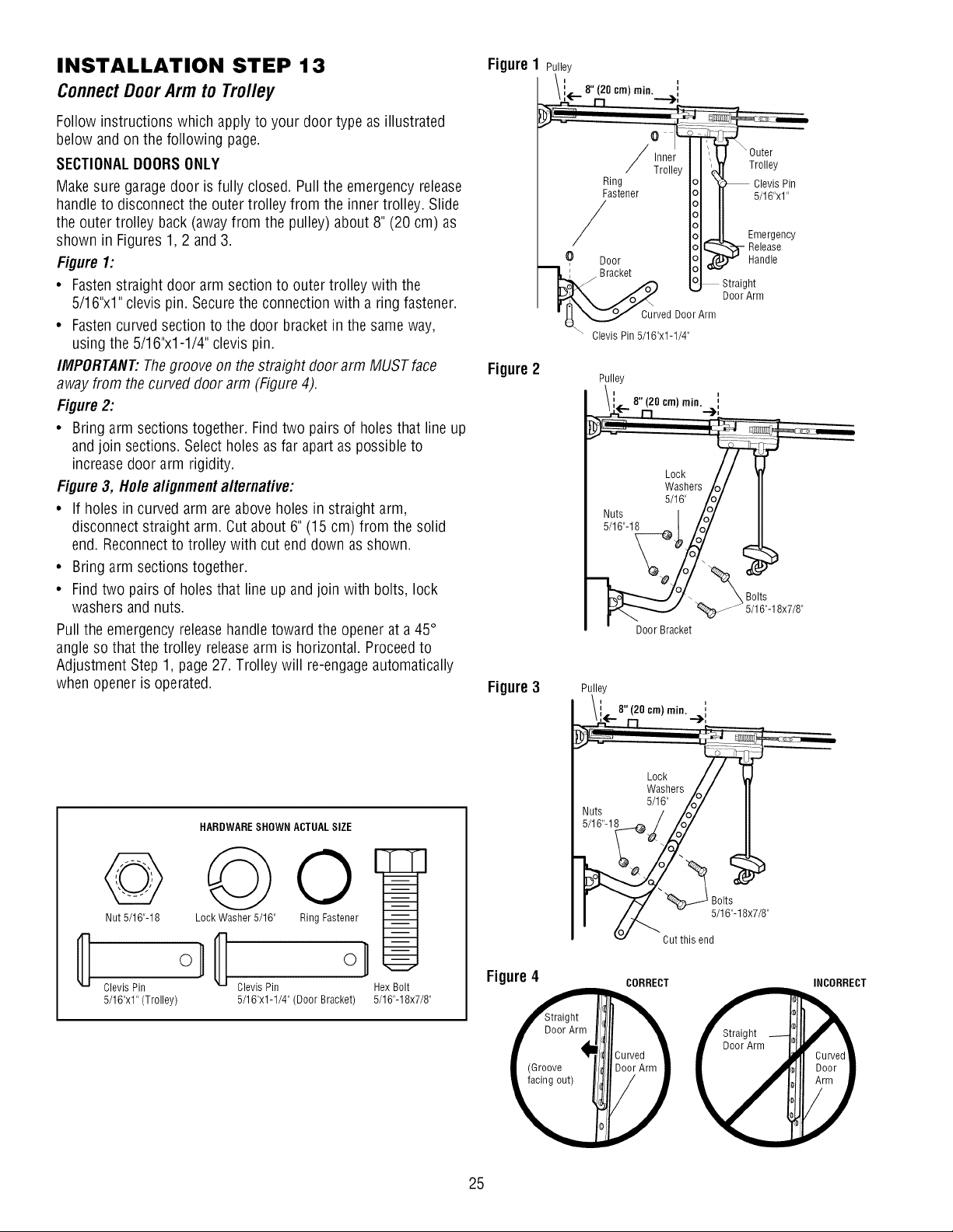
INSTALLATION STEP 13
ConnectDoorArm to Trolley
Follow instructions which apply to your door type as illustrated
below and on the following page.
SECTIONALDOORSONLY
Make sure garagedoor is fully closed. Pull the emergency release
handle to disconnect the outer trolley from the inner trolley. Slide
the outer trolley back (awayfrom the pulley) about 8" (20 cm) as
shown in Figures 1, 2 and 3.
Figure 1:
• Fastenstraight door arm section to outer trolley with the
5/16"x1" clevis pin. Secure the connection with a ring fastener.
• Fastencurved section to the door bracket in the same way,
using the 5/16"x1-1/4" clevis pin.
IMPORTANT'.Thegroove on the straight door arm MUST face
away from the curved door arm (Figure 4).
Figure 2:
• Bring arm sections together. Find two pairs of holes that line up
and join sections. Select holes as far apart as possible to
increase door arm rigidity.
Figure 3, Hole alignment alternative:
• If holes in curved arm are above holes in straight arm,
disconnect straight arm. Cut about 6" (15 cm) from the solid
end. Reconnectto trolley with cut end down as shown.
• Bring arm sections together.
• Find two pairs of holes that line up and join with bolts, lock
washers and nuts.
Pull the emergency releasehandle toward the opener at a 45°
angle so that the trolley releasearm is horizontal. Proceedto
Adjustment Step 1, page 27. Trolley will re-engageautomatically
when opener is operated.
HARDWARESHOWN ACTUALSIZE
o Qo
Nut 5/16"-18 Lock Washer 5/16" Ring Fastener
on
Clevis Pin Clevis Pin
5/16"x1" (Trolley) 5/16"x1-1/4" (Door Bracket)
Hex Bolt
5/16"-18x7/8"
Figure
Figure 2
Figure 3
Figure 4
(
Pulley
/i._8"(20°m)
Ring
Fastener
/
O Door
Bracket
Cuwed DoorArm
Clevis Pin 5/16"x1-1/4"
Pulley
i-- 8"(20 cm) min. i
Lock t
Washers/(
5/16" /oo]
_ult_._1 , /o/
Door Bracket
J
_ Bolts
5/16"-18x7/8"
Pulley
i " (20 cm) min. ,
Nuts / /o7'
5/16"-1_._/_
v Cut this end
Door Arm
(Groove
facing out)
CORRECT INCORRECT
25
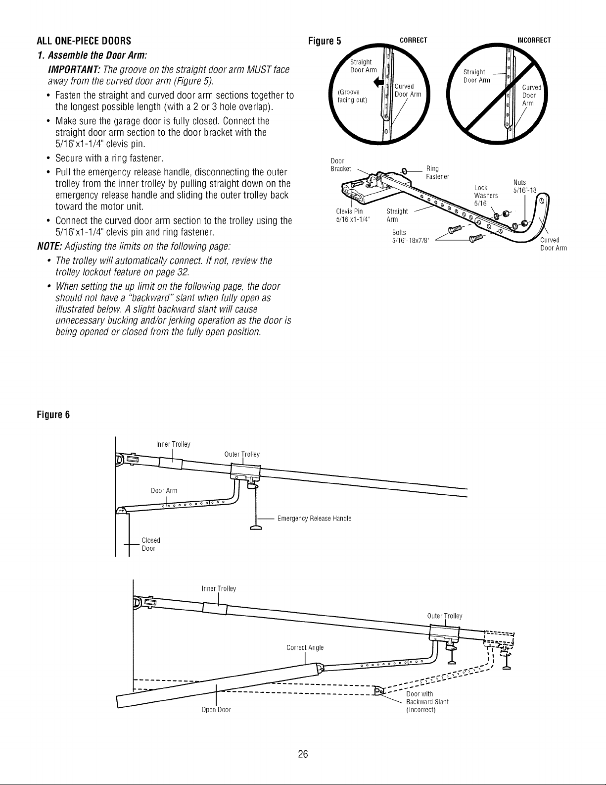
ALLONE-PIECEDOORS
1. Assemblethe DoorArm:
IMPORTANT:Thegroove on the straight door arm MUST face
away from the curved door arm (Figure 5).
• Fastenthe straight and curved door arm sections together to
the longest possible length (with a 2 or 3 hole overlap).
• Make sure the garage door is fully closed. Connect the
straight door arm section to the door bracket with the
5/16"x1-1/4" clevis pin.
• Secure with a ring fastener.
• Pull the emergency release handle, disconnecting the outer
trolley from the inner trolley by pulling straight down on the
emergency release handle and sliding the outer trolley back
toward the motor unit.
• Connect the curved door arm section to the trolley using the
5/16"x1-1/4" clevis pin and ring fastener.
NOTE:Adjusting the limits on the following page:
• Thetrofley will automatically connect. If not, review the
trolley lockout feature on page 32.
• Whensetting the up limit on the following page, the door
should not havea "backward" slant when fully open as
illustrated below. A slight backward slant will cause
unnecessarybucking and/or jerking operation as the door is
being opened or closed from the fully open position.
Door
Bracket
Clevis Pin
5/16"xl - 1/4"
CORRECT INCORRECT
__ Ring
Fastener
Straight
Arm
Bolts
5/16"-18x7/8"
Lock
Washers
5/16"
Nuts
5/16"-18
}u_ed
DoorArm
Figure 6
Inner Trolley
I _ Emergency Release Handle
Closed
I Door
Inner Trolley
Outer Trolley
Open Door
Backward Slant
(Incorrect)
26
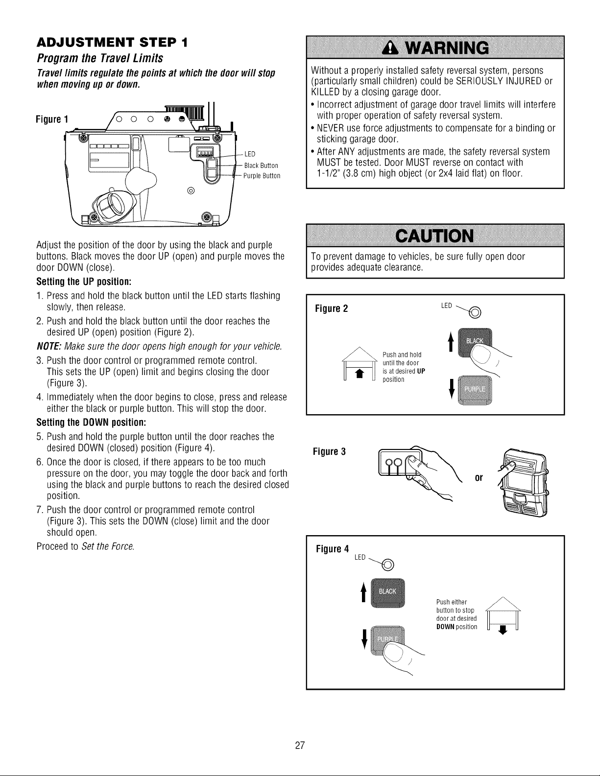
ADJUSTMENT STEP 1
Program the Travel Limits
Travel limits regulate the points at which the door will stop
whenmovingup or down.
Figure 1
Black Button
)le Button
Without a properly installed safety reversalsystem, persons
(particularly small children) could be SERIOUSLYINJUREDor
KILLEDby a closing garagedoor.
• Incorrect adjustment of garagedoor travel limits will interfere
with proper operation of safety reversal system.
• NEVERuse force adjustments to compensate for a binding or
sticking garage door.
• After ANY adjustments are made,the safety reversal system
MUST betested. Door MUST reverse on contact with
1-1/2" (3.8 cm) high object (or 2x4 laid flat) on floor.
Adjust the position of the door by using the black and purple
buttons. Blackmoves the door UP (open) and purple moves the
door DOWN(close).
Settingthe UP position:
1. Pressand hold the black button until the LED starts flashing
slowly, then release.
2. Push and hold the black button until the door reachesthe
desired UP (open) position (Figure 2).
NOTE:Make sure the door opens high enough for your vehicle.
3. Push the door control or programmed remote control.
This sets the UP (open) limit and begins closing the door
(Figure 3).
4. Immediately when the door begins to close, press and release
either the black or purple button. This will stop the door.
Settingthe DOWN position:
5. Push and hold the purple button until the door reachesthe
desired DOWN(closed) position (Figure 4).
6. Oncethe door is closed, if there appearsto be too much
pressure on the door, you may toggle the door back and forth
using the black and purple buttons to reach the desired closed
position.
7. Push the door control or programmed remote control
(Figure 3). This sets the DOWN(close) limit and the door
should open.
Proceed to Set the Force.
To prevent damage to vehicles, be sure fully open door
provides adequateclearance.
Figure 2 LED
Push and hold
until the door
is at desired UP
position
t
Figure 3
Figure 4
LED
Push either
button to stop
door at desired
DOWN position
27
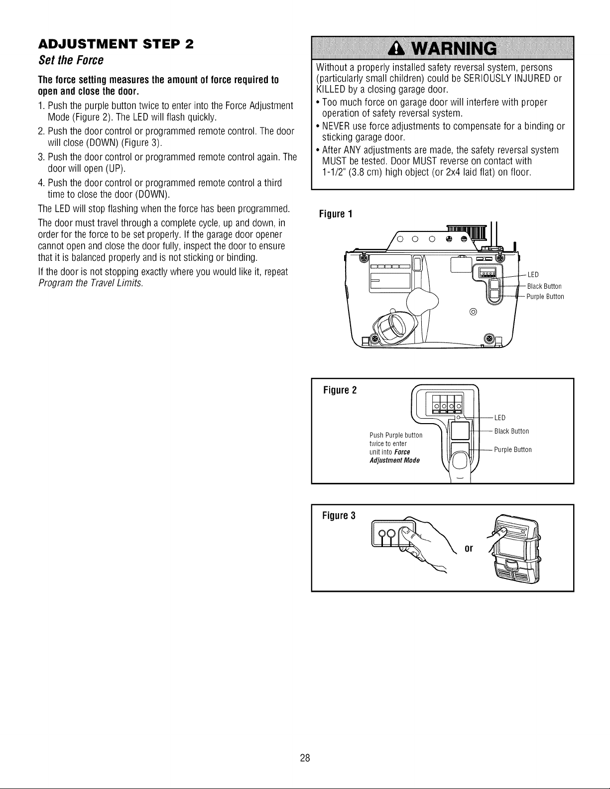
ADJUSTMENT STEP 2
Set the Force
Theforce setting measuresthe amountof force required to
openand close the door.
1. Push the purple button twice to enter into the ForceAdjustment
Mode (Figure 2). The LEDwill flash quickly.
2. Push the door control or programmed remotecontrol. The door
will close (DOWN) (Figure 3).
3. Push the door control or programmed remotecontrol again.The
door will open (UP).
4. Push the door control or programmed remotecontrol a third
time to closethe door (DOWN).
The LEDwill stop flashing when the force has been programmed.
The door must travel through a complete cycle, up and down, in
order for the force to beset properly. If the garagedoor opener
cannotopen and closethe door fully, inspect the door to ensure
that it is balancedproperly and is not sticking or binding.
If the door is not stopping exactlywhere you would like it, repeat
Program the TravelLimits.
Without a properly installed safety reversalsystem, persons
(particularly small children) could be SERIOUSLYINJUREDor
KILLEDby a closing garagedoor.
• Too much force on garage door will interfere with proper
operation of safety reversalsystem.
• NEVERuse force adjustments to compensate for a binding or
sticking garage door.
• After ANY adjustments are made,the safety reversal system
MUST betested. Door MUST reverse on contact with
1-1/2" (3.8 cm) high object (or 2x4 laid flat) on floor.
Figure 1
LED
)le Button
Figure 2
Push Purple button
twice to enter
unit into Force
Adjustment Mode
Button
)le Button
Figure 3
28
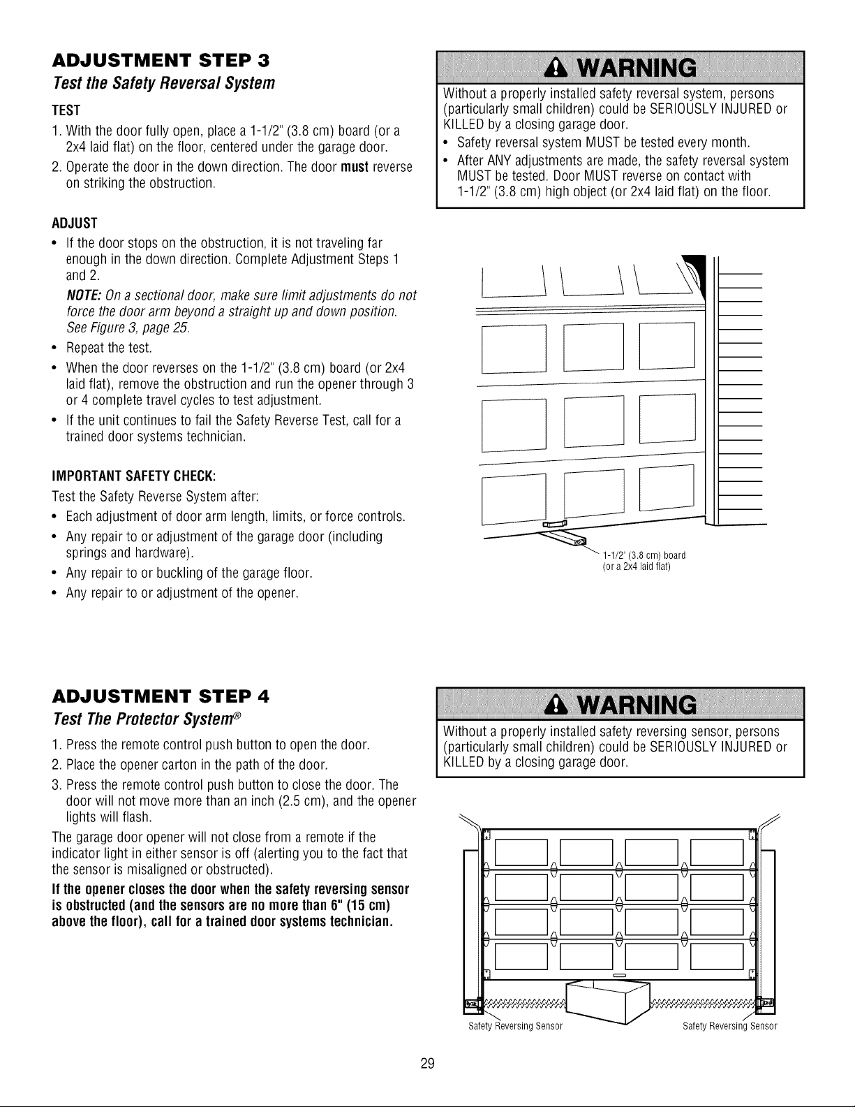
ADJUSTMENT STEP 3
Testthe SafetyReversalSystem
TEST
1. With the door fully open, place a 1-1/2" (3.8 cm) board (or a
2x4 laid flat) on the floor, centered under the garagedoor.
2. Operatethe door in the down direction. The door must reverse
on striking the obstruction.
ADJUST
• If the door stops on the obstruction, it is not traveling far
enough in the down direction. Complete Adjustment Steps 1
and 2.
NOTE:On a sectional door, make sure limit adjustments do not
force the door arm beyond a straight up and down position.
SeeFigure 3, page25.
• Repeatthe test.
• When the door reverses on the 1-1/2" (3.8 cm) board (or 2x4
laid flat), remove the obstruction and run the openerthrough 3
or 4 complete travel cycles to test adjustment.
• If the unit continues to fail the Safety ReverseTest, call for a
trained door systems technician.
IMPORTANTSAFETYCHECK:
Test the Safety ReverseSystem after:
• Each adjustment of door arm length, limits, or force controls.
• Any repair to or adjustment of the garagedoor (including
springs and hardware).
• Any repair to or buckling of the garagefloor.
• Any repair to or adjustment of the opener.
Without a properly installed safety reversalsystem, persons
(particularly small children) could be SERIOUSLYINJUREDor
KILLEDby a closing garagedoor.
• Safety reversalsystem MUST betested every month.
• After ANY adjustments are made,the safety reversal system
MUST be tested. Door MUST reverse on contact with
1-1/2" (3.8 cm) high object (or 2x4 laid flat) on the floor.
(or a 2x4 laid flat
ADJUSTMENT STEP 4
Test The ProtectorSysterr
1. Pressthe remote control push button to open the door.
2. Placethe opener carton in the path of the door.
3. Pressthe remote control push button to close the door. The
door will not move more than an inch (2.5 cm), and the opener
lights will flash.
The garage door openerwill not close from a remote if the
indicator light in either sensor is off (alerting you to the fact that
the sensor is misaligned or obstructed).
If the openerclosesthe doorwhen the safety reversingsensor
is obstructed(and the sensorsare no more than 6" (15 cm)
abovethe floor), call for a trained doorsystemstechnician.
Without a properly installed safety reversing sensor, persons
(particularly small children) could be SERIOUSLYINJUREDor
KILLEDby a closing garagedoor.
Safety Reversing Sensor Safety Reversing Sensor
29
OPERATION
IMPORTANTSAFETYINSTRUCTIONS
iiiiiiiiiiiiiiiiiiiiiiiiiiiiiiiiiiiiiiiiiiiiiiiiiiiiiiiiiiiiiiiiiiiiiiiiiiiiiiiiiiiiiiiiiiiiiiiiiiiiiiiiiiiiiiiiiiiiiiiiiiiiiiiiiiiiiiiiiiiiiiiiiiiiiiiiiiiiiiiiiiiiiiiiiiiiiiiiiiiiiiiiiiiiiiiiiiiiiiiiiiiiiiiiiiiiiiiiiiiiiiiiiiiiiiiiiiiiiiiiiiiiiiiiiiiiiiiiiiiiiiiiiiiiiiiiiiiiiiiiiiiiiiiiiiiiiiiiiiiiiiiiiiiiiiiiiiiiiiiiiiiiiiiiiiiiiiiiiiiiiiiiiiiiiiiiiiiiiiiiiiiiiiiiiiiiiiiiiiiiiiiiiiiiiiiiiiiiiiiiiiiiiiiiiiiiiiiiiiiiiiiiiiiiiiiiiiiiiiiiiiiiiiiiiiiiiiiiiiiiiiiiiiiiiiiiiiiiiiiiiiiiiiiiiiiiiiiiiiiiiiiiiiiiiiiiiiiiiiiiiiiiiiiiiiiiiiiiiiiiiiiiiiiiiiiiiiiiiiiiiiiiiiiiiiiiiiiiiiiiiiiiiiiiiiiiiiiiiiiiiiiiiiiiiiiiiiiiiiiiiiiiiiiiiiiiiiiiiiiiiiiiiiiiiiiiiiiiiiiiiiiiiiiiiiiiiiiiiiiiiiiiiiiiiiiiiiiiiiiiiiiiiiiiiiiiiiiiiiiiiiiiiiiiiiiiiiiiiiiiiiiiiiiiiiiiiiiiiiiiiiiiiiiiiiiiiiiiiiiiiiiiiiiiiiiiiiiiiiiiiiiiiiiiiiiiiiiiiiiiiiiiiiiiiiiiiiiiiiiiiiiiiiiiiiiiiiiiiiiiiiiiiiiiiiiiiiiiiiiiiiiiiiiiiiiiiiiiiiiiiiiiiiiiiiiiiiiiiiiiiiiiiiiiiiiiiiiiiiiiiiiiiiiiiiiiiiiiiiiiiiiiiiiiiiiiiiiiiiiiiiiiiiiiiiiiiiiiiiiiiiiiiiiiiiiiiiiiiiiiiiiiiiiiiiiiiiiiiiiiiiiiiiiiiiiiiiiiiiiiiiiiiiiiiiiiiiiiiiiiiiiiiiiiiiiiiiiiiiiiiiiiiiiiiiiiiiii
To reducethe riskof SEVEREINJURYor DEATH:
1. READAND FOLLOWALL WARNINGSAND INSTRUCTIONS.
2. ALWAYS keep remote controls out of reach of children.
NEVERpermit children to operate or play with garagedoor
control push buttons or remote controls.
3. ONLYactivate garagedoor when it can be seen clearly, it is
properly adjusted, and there are no obstructions to door
travel.
4. ALWAYS keep garage door in sight until completely closed.
NO ONESHOULDCROSSTHE PATH OFTHEMOVING
DOOR.
5. NO ONESHOULDGO UNDERA STOPPED,PARTIALLY
OPENDOOR.
6. If possible, use emergency releasehandle to disengage
trolley ONLYwhen garage door is CLOSED.Weak or broken
springs or unbalanceddoor could result in an open door
falling rapidly and/or unexpectedly, causing SEVERE
INJURYor DEATH.
7. NEVERuse emergency releasehandle unless garage
doorway is clear of persons and obstructions.
8. NEVERuse handle to pull garagedoor open or closed. If
rope knot becomes untied, you could fall.
9. If one control (force or travel limits) is adjusted, the other
control may also needadjustment.
10. After ANY adjustments are made, the safety reversal
system MUST be tested.
11. Safety reversal system MUST be tested every month.
Garagedoor MUST reverse on contact with 1-1/2"
(3.8 cm) high object (or a 2x4 laid flat) on the floor.
Failureto adjust the garagedoor opener properly may
cause SEVEREINJURY or DEATH.
12. ALWAYS KEEPGARAGEDOOR PROPERLYBALANCED
(see page 3). An improperly balanced door may NOT
reversewhen requiredand could result in SEVEREINJURY
or DEATH.
13. ALL repairs to cables, spring assemblies and other
hardware,ALL of which are under EXTREMEtension,
MUST be made by a trained door systems technician.
14. To avoid SERIOUSPERSONALINJURYor DEATHfrom
electrocution, disconnect ALL electric and battery power
BEFOREperforming ANY service or maintenance.
is SAVETHESEINSTRUCTIONS.
Using Your Garage Door Opener
Your Security÷ ® opener and hand-held remote control have been
factory-set to a matching code which changes with each use,
randomly accessing over 100 billion new codes. Your opener will
operate with up to ten Security÷ ® remote controls, one
Security÷ ® KeylessEntry System, and one accessory wall
control. If you purchasea new remote, or if you wish to
deactivateany remote, follow the instructions in the Programming
section.
Activateyour openerwithany of the following:
• The Hand-HeldRemote Control: Hold the large push button
down until the door starts to move.
• The Wall-Mounted Door Controh Hold the push button or bar
down until the door starts to move.
• The KeylessEntry (seeAccessories): If provided with your
garagedoor opener, it must be programmed before use. See
Programming.
Whenthe opener is activated(with the safety reversingsensor
correctlyinstalled and aligned)
1. If open, the door will close. If closed, it will open.
2. If closing, the door will reverse.
3. If opening, the door will stop.
4. If the door has been stopped in a partially open position, it will
close.
5. If obstructed while closing, the door will reverse. If the
obstruction interrupts the sensor beam, the opener lights will
blink for five seconds.
3O
6. If obstructed while opening, the door will stop.
7. If fully open, the door will not close when the beam is broken.
The sensor has no effect in the opening cycle.
If the sensor is not installed, or is misaligned, the door won't
close from a hand-held remote. However,you can close the door
with the door control, the Outdoor Key Switch, or KeylessEntry, if
you activate them until down travel is complete. If you release
them too soon, the door will reverse.
Theopenerlightswill turn on under the following conditions:
when the opener is initially plugged in; when power is restored
after interruption; when the opener is activated.
They will turn off automatically after 4-1/2 minutes or provide
constant light when the Light feature on the door control is
activated. Bulb size is A19. Bulb power is 100 watts maximum.
Security÷_ light feature:Lights will also turn on when someone
walks through the open garage door. With a Smart Control
Panel®, this feature may be turned off as follows: With the opener
lightsoff, press and hold the light button for 10 seconds, until the
lightgoes on, then off again. To restore this feature, start with the
opener lightson, then press and hold the lightbutton for 10
seconds until the lightgoes off, then on again.
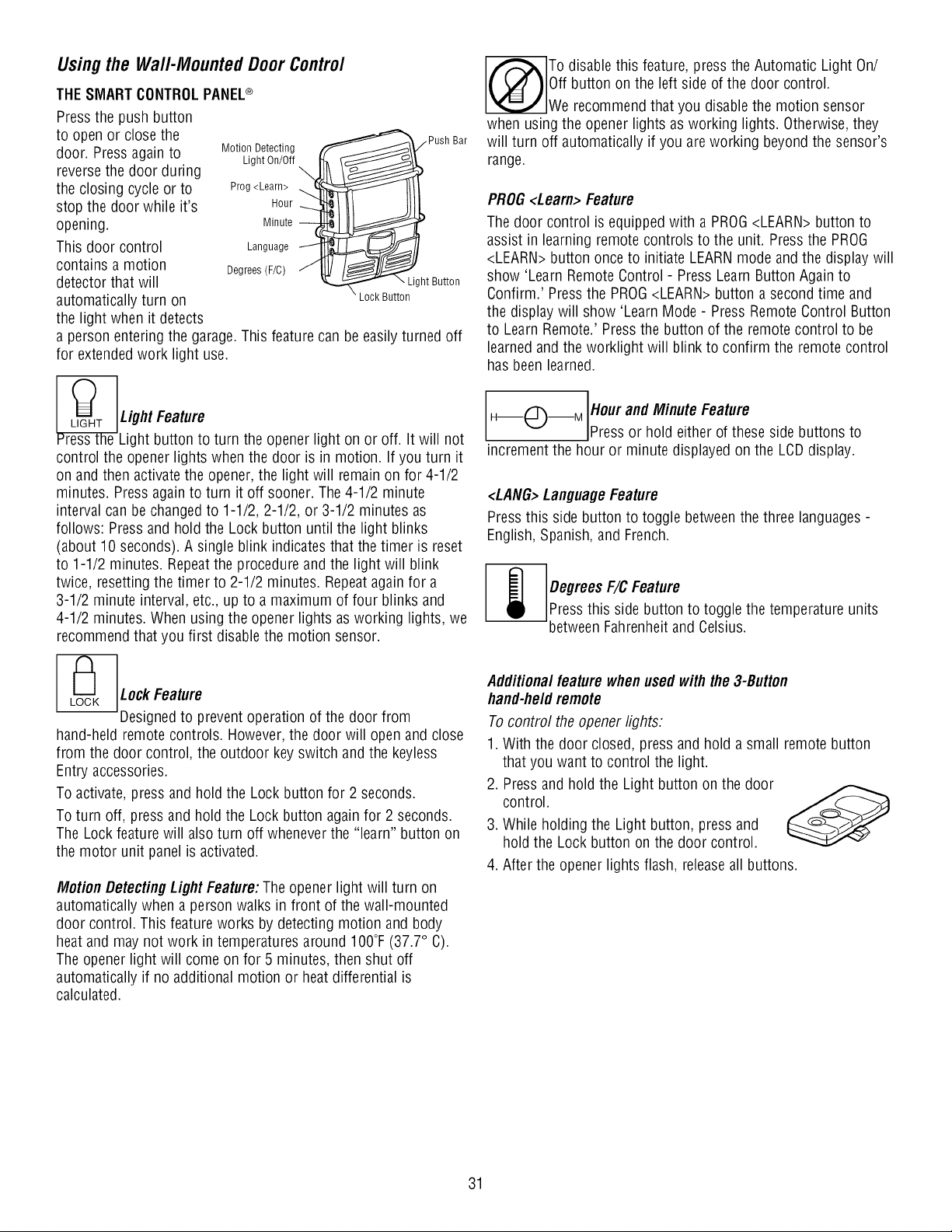
Usingthe Wall-MountedDoor Control
THESMARTCONTROLPANEL®
Press the push button
to open or close the
door. Pressagain to
reversethe door during
the closing cycle or to
stop the door while it's
opening.
This door control
contains a motion
detector that will
automatically turn on
the light when it detects
Motion Detecting
Light On/Off
Prog <Learn> _
Hour
Minute --
Language _i
Degrees (F/C) J
L Push Bar
_"- LightButton
\ Lock Button
a person entering the garage. This feature can be easily turned off
for extendedwork light use.
pr_t__sHtheUgg_:uet_Unr[oturn the opener light on or off. it will not
control the opener lights when the door is in motion. If you turn it
on and then activate the opener, the light will remain on for 4-1/2
minutes. Press again to turn it off sooner. The 4-1/2 minute
interval can be changed to 1-1/2, 2-1/2, or 3-1/2 minutes as
follows: Press and hold the Lock button until the light blinks
(about 10 seconds). A single blink indicates that the timer is reset
to 1-1/2 minutes. Repeatthe procedure and the light will blink
twice, resetting the timer to 2-1/2 minutes. Repeat againfor a
3-1/2 minute interval, etc., up to a maximum of four blinks and
4-1/2 minutes. When using the opener lights as working lights, we
recommend that you first disable the motion sensor.
LO_CK LD_[_gnF_ttor_revent operation of the door from
hand-held remote controls. However, the door will open and close
from the door control, the outdoor key switch and the keyless
Entry accessories.
To activate, press and hold the Lock button for 2 seconds.
To turn off, press and hold the Lock button again for 2 seconds.
The Lock feature will also turn off whenever the "learn" button on
the motor unit panel is activated.
Motion Detecting Light Feature:The opener light will turn on
automatically when a person walks in front of the wall-mounted
door control. This feature works by detecting motion and body
heat and may not work in temperatures around IO0°F (37.7° C).
The opener light will come on for 5 minutes, then shut off
automatically if no additional motion or heat differential is
calculated.
To disable this feature, press the Automatic Light On/
Off button on the left side of the door control.
We recommend that you disable the motion sensor
when using the opener lights as working lights. Otherwise, they
will turn off automatically if you are working beyond the sensor's
range.
PROG<Learn> Feature
The door control is equipped with a PROG<LEARN>button to
assist in learning remote controls to the unit. Press the PROG
<LEARN>button once to initiate LEARNmode and the display will
show 'Learn Remote Control - Press Learn Button Again to
Confirm.' Press the PROG<LEARN>button a second time and
the display will show 'Learn Mode - Press Remote Control Button
to Learn Remote.' Press the button of the remote control to be
learned and the worklight will blink to confirm the remote control
has been learned.
H--I_'_--M Hour andMinute Feature
Press or hod ether of these side buttons to
increment the hour or minute displayed on the LCDdisplay.
<LAHG>LanguageFeature
Press this side button to toggle betweenthe three languages-
English, Spanish, and French.
Degrees F/C Feature
Pressthis side button to toggle the temperature units
betweenFahrenheitand Celsius.
Additionalfeature whenusedwith the 3-Button
hand-heldremote
To control the opener lights:
1. With the door closed, press and hold a small remote button
that you want to control the light.
2. Pressand hold the Light button on the door
control.
3. While holding the Light button, press and
hold the Lock button on the door control.
4. After the opener lights flash, releaseall buttons.
31
Care of YourOpener
MAINTENANCESCHEDULE
Oncea Month
• Manually operate door. If it is unbalancedor binding, call a
trained door systems technician.
• Checkto be sure door opens and closes fully. Adjust limits
and/or force if necessary (see pages27 and 28).
• Repeatthe safety reversetest. Make any necessary
adjustments (SeeAdjustment Step 3).
Oncea Year
• Oil door rollers, bearings and hinges. The opener does not
require additional lubrication. Do not greasethe door tracks.
To Openthe DoorManually
To prevent possible SERIOUSINJURYor DEATHfrom a falling
garagedoor:
• If possible, use emergency releasehandleto disengage
trolley ONLYwhen garagedoor is CLOSED.Weak or broken
springs or unbalanceddoor could result in an open door
falling rapidly and/or unexpectedly.
• NEVERuse emergency releasehandle unless garagedoorway
is clear of persons and obstructions.
• NEVERuse handle to pull door open or closed. If rope knot
becomes untied, you could fall.
THEREMOTECONTROLBATTERY
To prevent possible SERIOUSINJURYor DEATH:
• NEVERallow small children near batteries.
• If battery is swallowed, immediately notify doctor.
To reduce risk of fire, explosion or chemical burn:
• ReplaceONLYwith 3V2032 coin batteries.
• DONOT recharge, disassemble, heat above 212° F (100° C)
or incinerate.
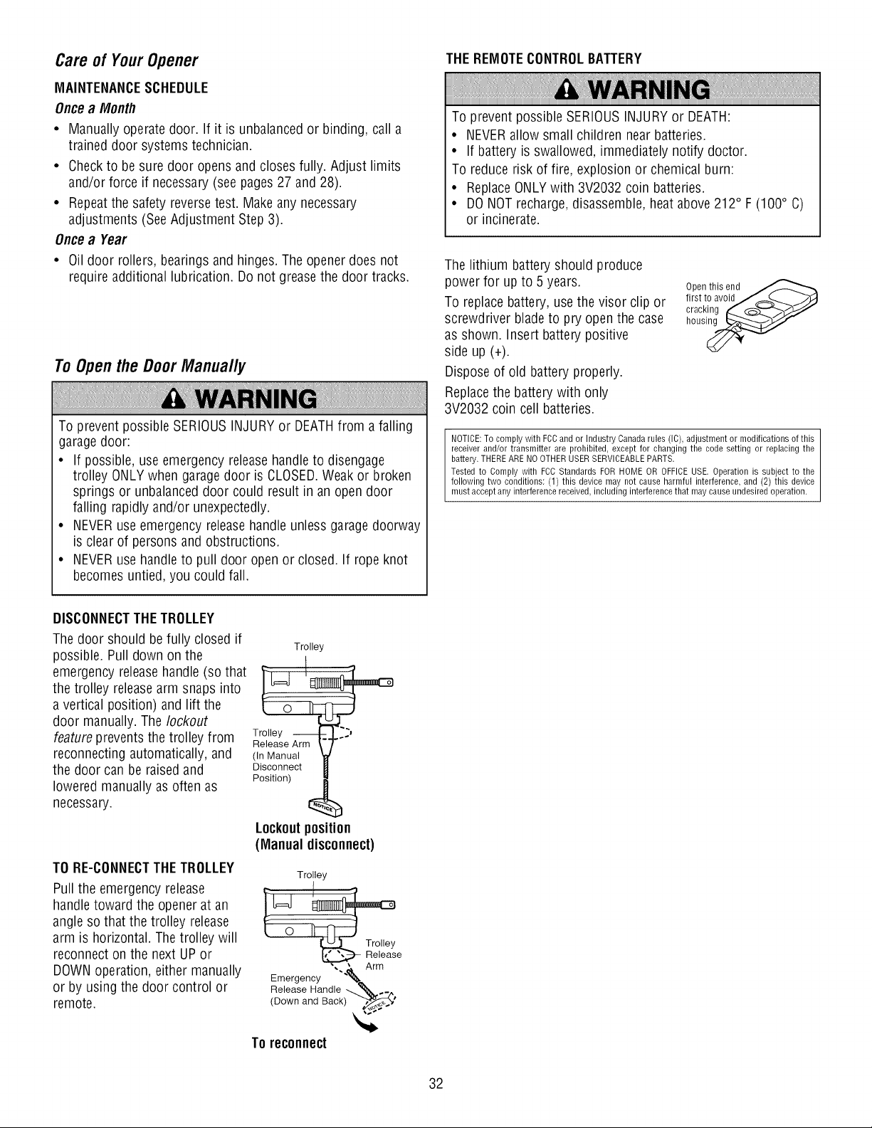
The lithium battery should produce
power for up to 5 years.
To replace battery, use the visor clip or
screwdriver blade to pry open the case
as shown. Insert battery positive
side up (+).
Dispose of old battery properly.
Replacethe battery with only
3V2032 coin cell batteries.
Open this end ,,,,,,_,_
first to avoid/_(....._ j-'_
cracking _ (_L.__/
hous_
NOTICE: To comply with FCC and or Industry Canada rules (IC), adjustment or modifications of this
receiver and/or transmitter are prohibited, except for changing the code setting or replacing the
battery. THERE ARE NO OTHER USER SERVICEABLE PARTS,
Tested to Comply with FCC Standards FOR HOME OR OFFICE USE, Operation is subject to the
following two conditions: (1) this device may not cause harmful interference, and (2) this device
must accept any interference received, including interference that may cause undesired operation.
DISCONNECTTHE TROLLEY
The door should be fully closed if
possible. Pull down on the
emergency releasehandle (so that
the trolley releasearm snaps into
a vertical position) and lift the
door manually. The lockout
feature prevents the trolley from
reconnecting automatically, and
the door can be raised and
lowered manually as often as
necessary.
TO RE-CONNECTTHE TROLLEY
Pull the emergency release
handle toward the opener at an
angle so that the trolley release
arm is horizontal. The trolley will
reconnect on the next UP or
DOWNoperation, either manually
or by using the door control or
remote.
Trolley
Trolley ...J
Release Arm
(In Manual
Disconnect
Position)
Lockoutposition
(Manual disconnect)
Trolley
Release
Emergency \ ._Arm
Release Handle _ _ ._
(Down and Back) ."_._,_'
TOreconnect
32
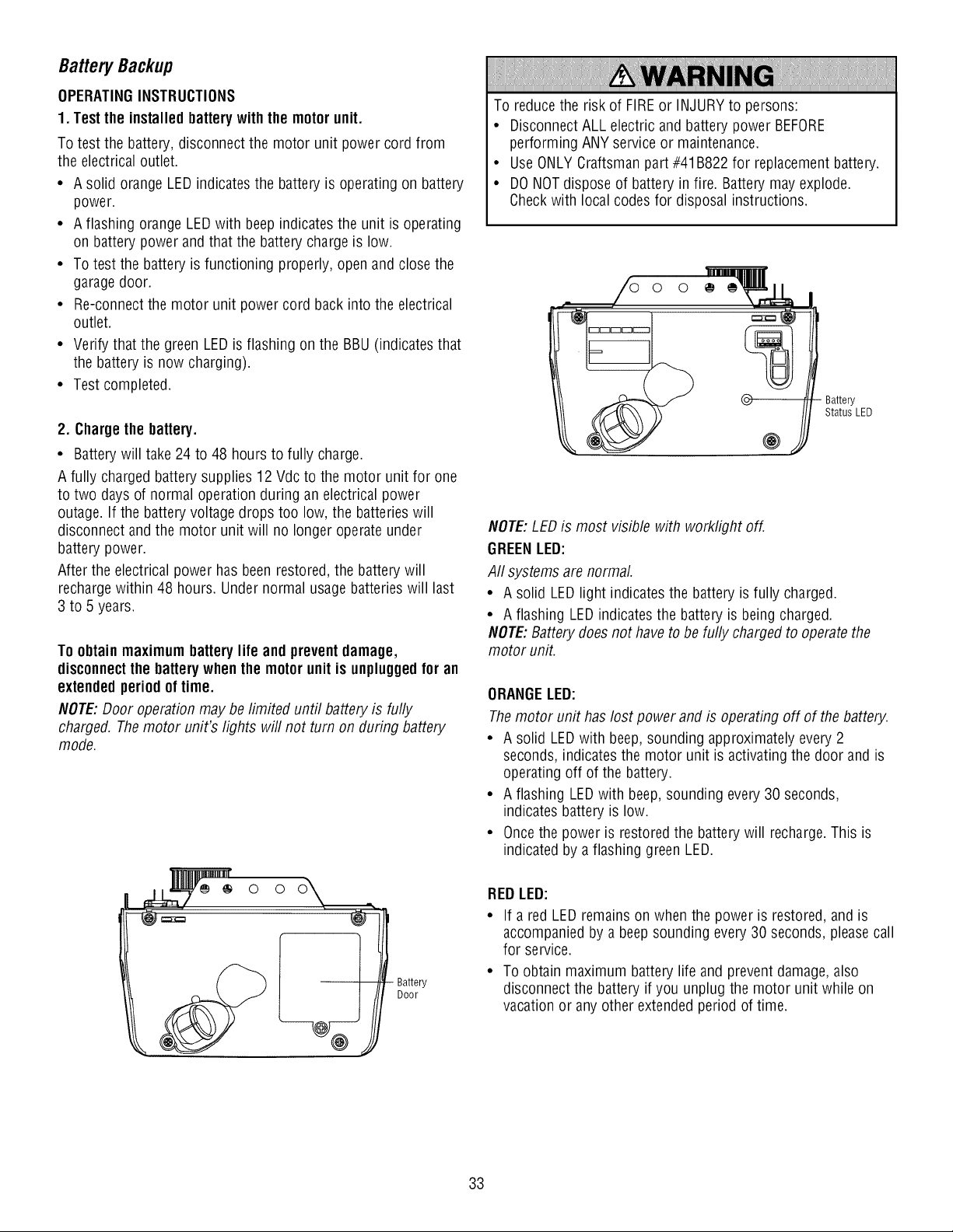
Battery Backup
OPERATINGINSTRUCTIONS
1. Test the installed battery with the motor unit.
To test the battery, disconnect the motor unit power cord from
the electrical outlet.
• A solid orange LED indicates the battery is operating on battery
power.
• A flashing orange LEDwith beep indicates the unit is operating
on battery power and that the battery charge is low.
• To test the battery is functioning properly, open and close the
garagedoor.
• Re-connect the motor unit power cord back into the electrical
outlet.
• Verify that the green LEDis flashing on the BBU(indicates that
the battery is now charging).
• Test completed.
2. Chargethe battery.
• Batterywill take 24 to 48 hours to fully charge.
A fully charged battery supplies 12 Vdc to the motor unit for one
to two days of normal operation during an electrical power
outage. If the battery voltage drops too low, the batteries will
disconnect and the motor unit will no longer operate under
battery power.
After the electrical power has beenrestored, the battery will
recharge within 48 hours. Under normal usage batteries will last
3 to 5 years.
To obtainmaximumbattery life and prevent damage,
disconnectthe batterywhenthe motor unit is unpluggedfor an
extendedperiod of time.
NOTE:Door operation may be limited until battery is fully
charged. The motor unit's lights will not turn on during battery
mode.
o o
Battery
Door
To reduce the risk of FIREor INJURY to persons:
• DisconnectALL electric and battery power BEFORE
performing ANY service or maintenance.
• UseONLY Craftsman part #41B822 for replacementbattery.
• DONOT dispose of battery in fire. Battery may explode.
Check with local codes for disposal instructions.
Battery
Status LED
@
NOTE:LED is most visible with worklight off.
GREENLED:
Aft systems are normal
• A solid LEDlight indicates the battery is fully charged.
• A flashing LEDindicates the battery is being charged.
NOTE:Battery does not have to be fully charged to operatethe
motor unit.
ORANGELED:
Themotor unit has lost power and is operating off of the battery.
• A solid LEDwith beep, sounding approximately every 2
seconds, indicates the motor unit is activating the door and is
operating off of the battery.
• A flashing LEDwith beep, sounding every 30 seconds,
indicates battery is low.
• Once the power is restored the battery will recharge.This is
indicated by a flashing green LED.
REDLED:
• If a red LED remains on when the power is restored, and is
accompanied by a beepsounding every 30 seconds, please call
for service.
• To obtain maximum battery life and prevent damage, also
disconnect the battery if you unplug the motor unit while on
vacation or any other extended period of time.
33
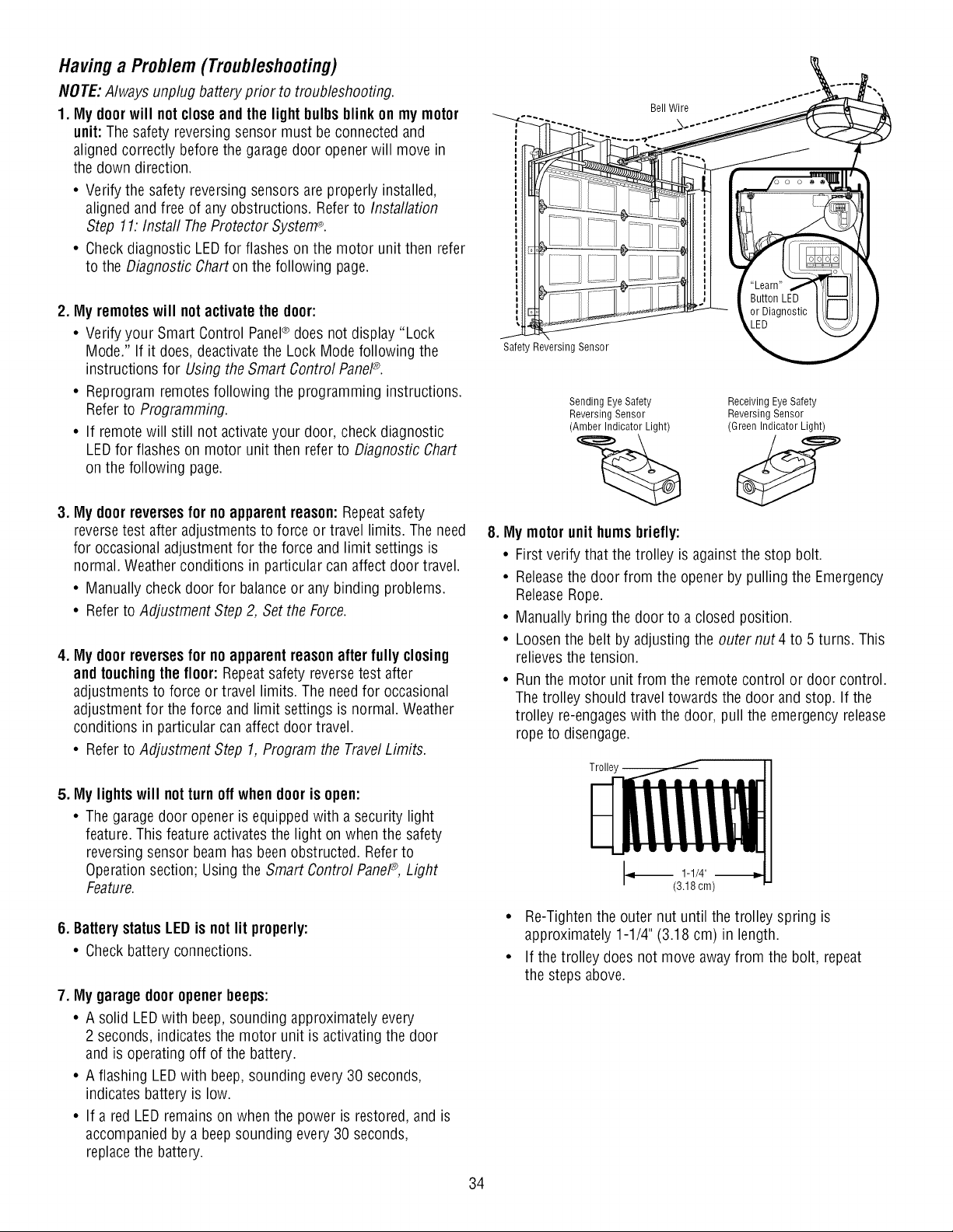
Having a Problem (Troubleshooting)
NOTE: Always unplug battery prior to troubleshooting.
1. My doorwill notclose and the light bulbs blink on my motor
unit: The safety reversing sensor must be connected and
aligned correctly before the garage door opener will move in
the down direction.
• Verify the safety reversing sensors are properly installed,
aligned and free of any obstructions. Refer to Installation
Step 11: Instafl TheProtector System®.
• Check diagnostic LED for flashes on the motor unit then refer
to the Diagnostic Chart on the following page.
2. My remotes will not activate the door:
• Verify your Smart Control Panel® does not display "Lock
Mode." If it does, deactivatethe Lock Mode following the
instructions for Using the Smart Control PaneP.
• Reprogram remotes following the programming instructions.
Refer to Programming.
• If remote will still not activateyour door, check diagnostic
LED for flashes on motor unit then refer to Diagnostic Chart
on the following page.
3. My doorreversesfor no apparent reason: Repeat safety
reversetest after adjustments to force or travel limits. The need
for occasional adjustment for the force and limit settings is
normal. Weather conditions in particular can affect door travel.
• Manually check door for balanceor any binding problems.
• Refer to Adjustment Step 2, Set the Force.
4. My doorreversesfor no apparent reason after fully closing
and touchingthe floor: Repeatsafety reverse test after
adjustments to force or travel limits.The need for occasional
adjustment for the force and limitsettings is normal. Weather
conditions in particular can affect door travel.
• Refer to Adjustment Step 1, Program the TravelLimits.
5. My lightswill notturn off when door is open:
• The garage door opener is equipped with a security light
feature. This feature activates the light on when the safety
reversing sensor beam has been obstructed. Refer to
Operation section; Using the Smart Control PaneP, Light
Feature.
6. Batterystatus LED is not lit properly:
• Check battery connections.
7. My garage door opener beeps:
• A solid LEDwith beep, sounding approximately every
2 seconds, indicates the motor unit is activating the door
and is operating off of the battery.
• A flashing LEDwith beep, sounding every 30 seconds,
indicates battery is low.
• If a red LED remains on when the power is restored, and is
accompanied by a beepsounding every 30 seconds,
replace the battery.
Bell Wire
J
Safety Reversing Sensor
"Learn"
Button LED
or Diagnostic )
Sending Eye Safety
Reversing Sensor
(Amber Indicator Light)
8. My motor unit hums briefly:
Receiving Eye Safety
Reversing Sensor
(Green Indicator Light)
• First verify that the trolley is againstthe stop bolt.
• Releasethe door from the opener by pulling the Emergency
ReleaseRope.
• Manually bring the door to a closed position.
• Loosen the belt by adjusting the outernut4 to 5 turns. This
relieves the tension.
• Run the motor unit from the remote control or door control.
The trolley should travel towards the door and stop. If the
trolley re-engageswith the door, pull the emergency release
rope to disengage.
Trolley --
• Re-Tighten the outer nut until the trolley spring is
approximately 1-1/4" (3.18 cm) in length.
• If the trolley does not move away from the bolt, repeat
the steps above.
34
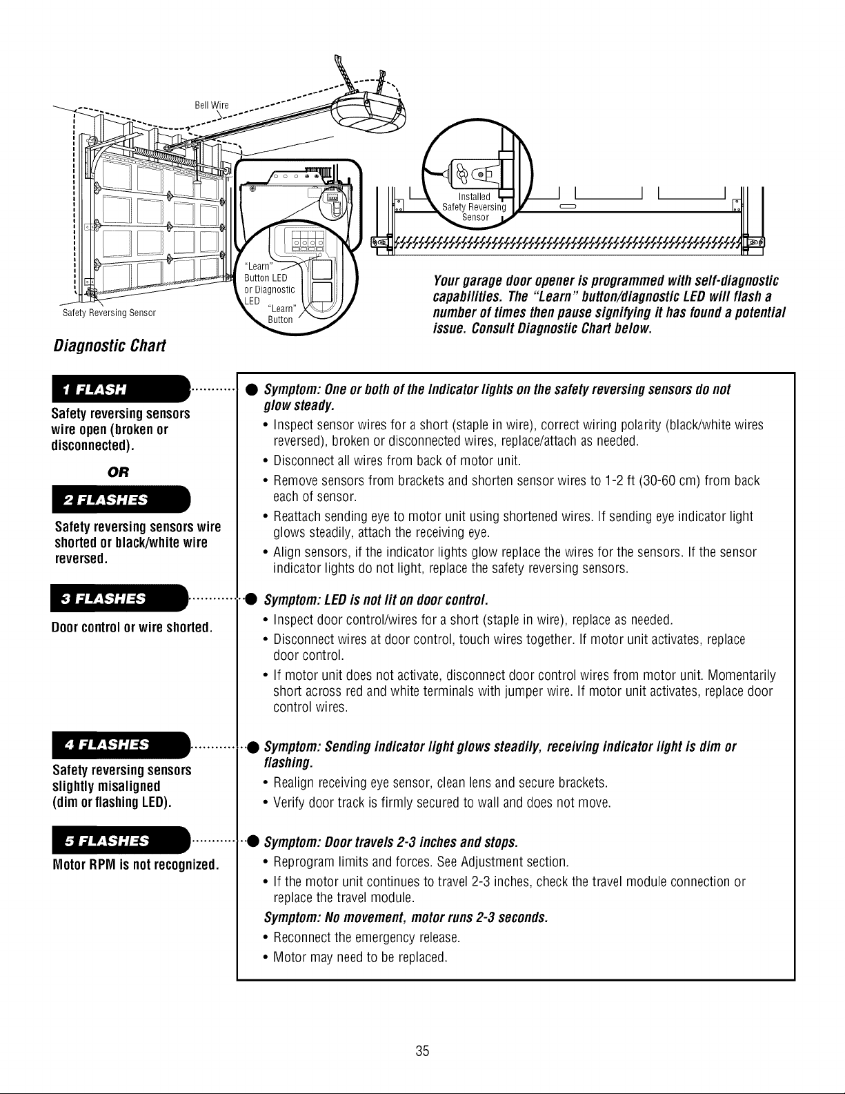
DiagnosticChart
I L
Yourgarage door opener is programmedwithserf-diagnostic
capabilities. The "Learn" button/diagnosticLED wi// f/ash a
numberof times then pause signifyingit has found a potential
issue. ConsultDiagnostic Chartbelow.
Safetyreversingsensors
wire open (brokenor
disconnected).
OR
Safetyreversingsensorswire
shortedor black/whitewire
reversed.
Doorcontrolor wire shorted.
Safetyreversingsensors
slightly misaligned
(dim orflashingLED).
Motor RPM is not recognized.
• Symptom:Oneor bothof the Indicatorfights onthe safety reversingsensorsdo not
glowsteady.
• Inspect sensor wires for a short (staple in wire), correct wiring polarity (black/white wires
reversed), broken or disconnected wires, replace/attachas needed.
• Disconnect all wires from back of motor unit.
• Remove sensors from brackets and shorten sensor wires to 1-2 ft (30-60 cm) from back
each of sensor.
• Reattach sending eye to motor unit using shortened wires. If sending eye indicator light
glows steadily, attach the receiving eye.
• Align sensors, if the indicator lights glow replace the wires for the sensors. If the sensor
indicator lights do not light, replacethe safety reversing sensors.
•.0 Symptom:LEDis notlit on doorcontrol.
• Inspect door control/wires for a short (staple in wire), replace as needed.
• Disconnect wires at door control, touch wires together. If motor unit activates, replace
door control.
• If motor unit does not activate, disconnect door control wires from motor unit. Momentarily
short across red and white terminals with jumper wire. If motor unit activates, replacedoor
control wires.
•.• Symptom:Sendingindicatorfight glows steadily, receivingindicatorfight is dim or
flashing.
• Realign receiving eye sensor, clean lens and secure brackets.
• Verify door track is firmly securedto wall and does not move.
•.• Symptom:Doortravels 2-3 inches andstops.
• Reprogram limits andforces. See Adjustment section.
• If the motor unit continues to travel 2-3 inches, check the travel module connection or
replace the travel module.
Symptom:Nomovement, motor runs2-3 seconds.
• Reconnect the emergency release.
• Motor may need to be replaced.
35
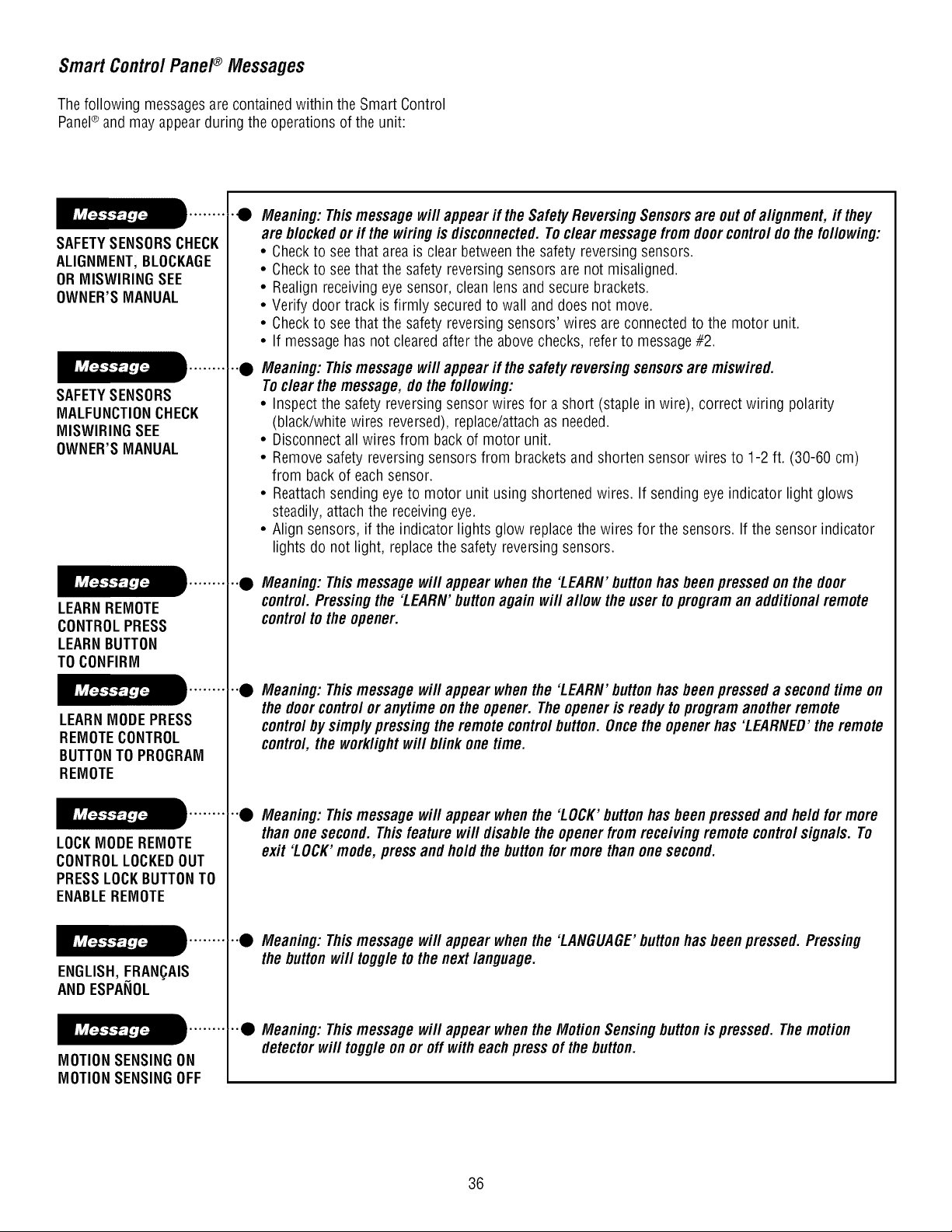
Smart ControlPanel®Messages
The following messagesare contained within the Smart Control
Panel® and may appear during the operations of the unit:
SAFETYSENSORSCHECK
ALIGNMENT,BLOCKAGE
OR IVIISWIRINGSEE
OWNER'SMANUAL
SAFETYSENSORS
MALFUNCTIONCHECK
IVIISWIRINGSEE
OWNER'SMANUAL
LEARNREMOTE
CONTROLPRESS
LEARNBUTTON
TO CONFIRM
LEARNMODEPRESS
REMOTECONTROL
BUTTONTO PROGRAM
REMOTE
LOCKMODE REMOTE
CONTROLLOCKEDOUT
PRESSLOCKBUTTONTO
ENABLEREMOTE
ENGLISH,FRAN_AIS
AND ESPANOL
MOTIONSENSINGON
MOTIONSENSINGOFF
•4) Meaning: Thismessage wi//appear if the SafetyReversingSensorsare out ofalignment, if they
are blockedorif the wiring is disconnected.Tocleat messagefrom doorcontrol do the following:
• Checkto see that areais clear between the safety reversing sensors.
• Checkto see that the safety reversing sensors are not misaligned.
• Realign receiving eye sensor, clean lens and secure brackets.
• Verify door track is firmly securedto wall and does not move.
• Checkto see that the safety reversing sensors' wires are connected to the motor unit.
• If message has not cleared after the above checks, refer to message#2.
•"0 Meaning: Thismessage will appear if the safety reversingsensors are miswired.
Tocleat the message,do the following:
• Inspect the safety reversing sensor wires for a short (staple in wire), correct wiring polarity
(black/white wires reversed), replace/attachas needed.
• Disconnect all wires from back of motor unit.
• Remove safety reversing sensors from brackets and shorten sensor wires to 1-2 ft. (30-60 cm)
from backof each sensor.
• Reattach sending eye to motor unit using shortened wires. If sending eye indicator light glows
steadily, attach the receiving eye.
• Align sensors, if the indicator lights glow replace the wires for the sensors. If the sensor indicator
lights do not light, replacethe safety reversingsensors.
•"0 Meaning: Thismessage wi//appear whenthe 'LEARN' buttonhas beenpressed on the door
control Pressingthe 'LEARN' buttonagain wi// a/low the user to program an additional remote
controlto the opener.
•"0 Meaning: Thismessage will appear when the 'LEARN' buttonhas been presseda second time on
the doorcontrol or anytime on the opener. The opener is ready to program anotherremote
controlby simplypressing the remote controlbutton. Oncethe openerhas 'LEARNED'the remote
control,the work/ightwi// b/ink one time.
•"0 Meaning: Thismessage wi//appear when the 'LOCK' buttonhas been pressed and held for more
thanone second. Thisfeature wi// disablethe openerfromreceiving remote controlsignals. To
exit 'LOCK'mode, press and hold the buttonfor more than one second.
•"0 Meaning: Thismessage will appear when the 'LANGUAGE'buttonhas been pressed. Pressing
the button wi// toggle to the next language.
•"• Meaning: Thismessage will appear whenthe Motion Sensing buttonis pressed. The motion
detectorwi// toggle on or off with each pressof the button.
36
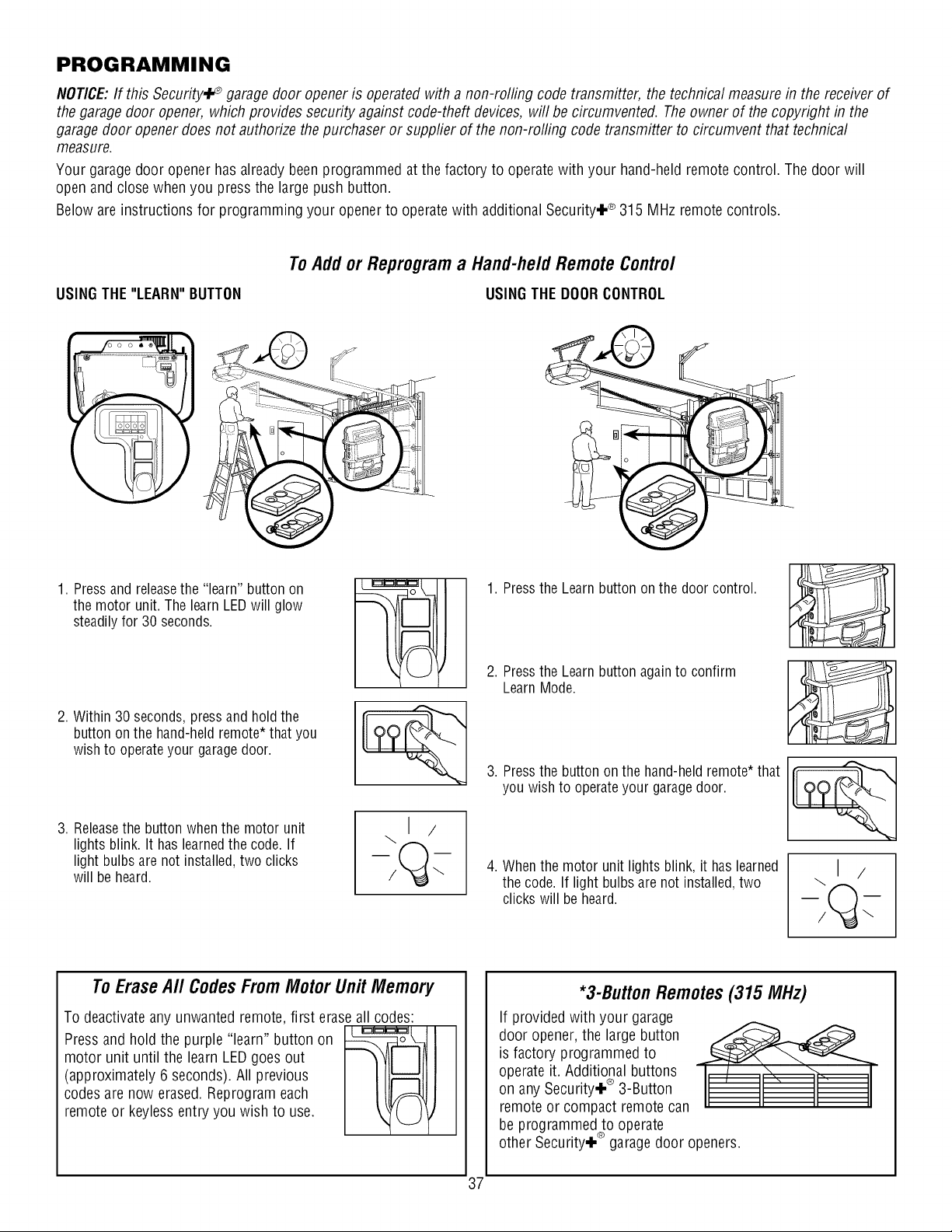
PROGRAMMING
NOTICE:If this Security,i_ garage door opener is operated with a non-rolling code transmitter, the technical measure in the receiver of
the garage door opener, which provides security against code-theft devices, will be circumvented. Theowner of the copyright in the
garage door opener does not authorize the purchaser or suppfier of the non-rolling code transmitter to circumvent that technical
measure.
Your garage door opener has already been programmed at the factory to operate with your hand-held remote control. The door will
open and close when you press the large push button.
Below are instructions for programming your opener to operate with additional Security÷ ® 315 MHz remote controls.
USINGTHE "LEARN" BUTTON
To Add or Reprogram a Hand-he/d Remote Contro/
USINGTHE DOORCONTROL
1. Pressandreleasethe "learn" button on
the motor unit.The learn LEDwill glow
steadilyfor 30 seconds.
2. Within 30 seconds,pressand holdthe
button onthe hand-heldremote*that you
wishto operateyour garagedoor.
3. Releasethe button whenthe motor unit
lights blink. It has learnedthe code. If
light bulbs are not installed,two clicks
will be heard.
1. Pressthe Learn button on the door control.
2. Pressthe Learn button again to confirm
LearnMode.
3. Pressthe button on the hand-heldremote*that
you wish to operateyour garagedoor.
4. Whenthe motor unit lights blink, it has learned
the code. If light bulbs are not installed,two
clicks will be heard.
\1 /
To Erase A// Codes From Motor Unit Memory
codes are now erased.Reprogram each
remote or keyless entry you wish to use.
To deactivateany unwanted remote, first erase all codes:
Pressand hold the purple "learn" button on __-_1 I
motor unit until the learn LEDgoes out
(approximately 6 seconds). All previous
*3-Button Remotes (315 MHz)
If provided with your garage
door opener, the large button
is factory programmed to
operate it. Additional buttons
on any Security÷ ® 3-Button
remote or compact remote can
be programmed to operate
other Security÷ ® garagedoor openers.
37
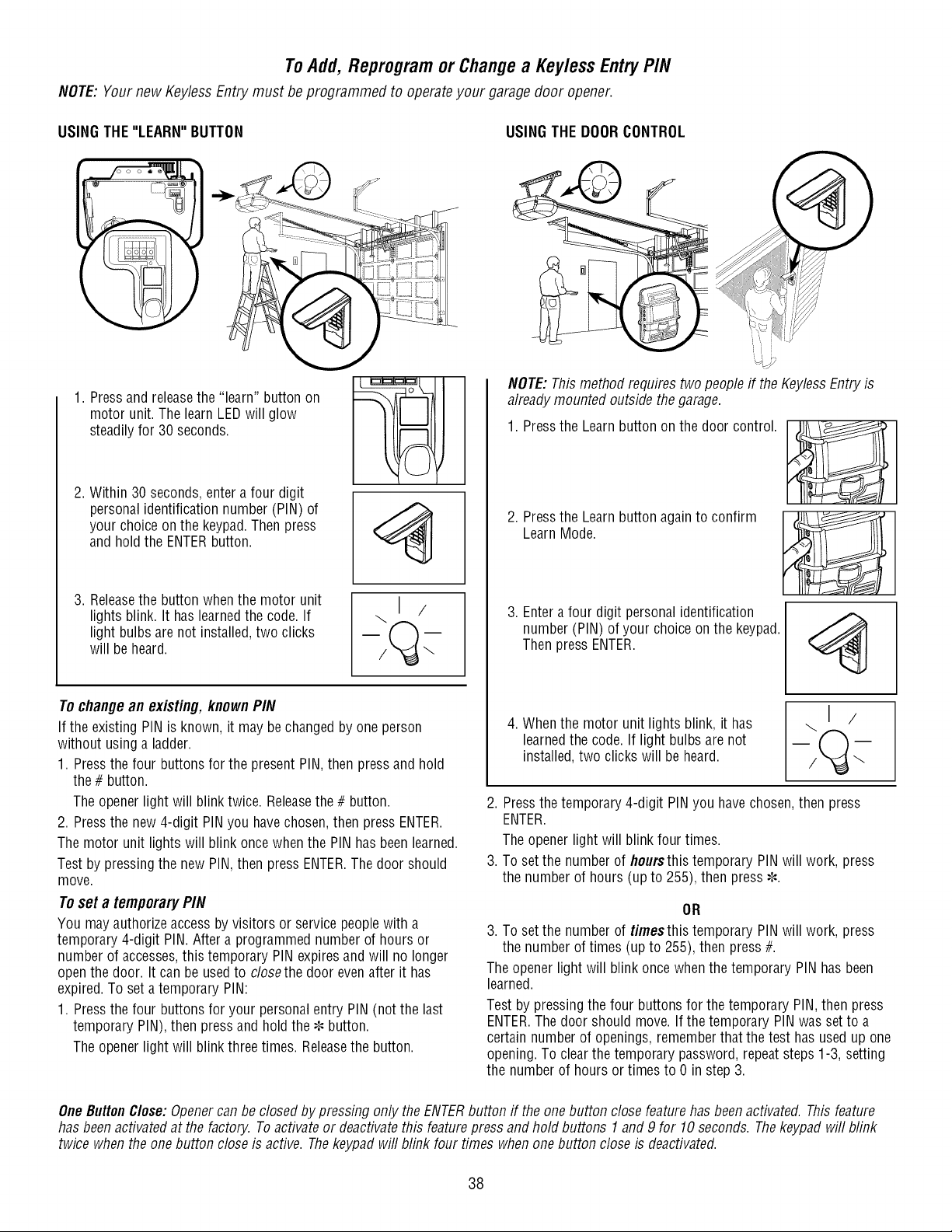
To Add, Reprogram or Change a Key/ess Entry PIN
NOTE:Your new KeylessEntry must be programmed to operate your garage door opener.
USINGTHE "LEARN" BUTTON USINGTHE DOORCONTROL
1. Pressand releasethe "learn" button on
motor unit. The learn LEDwill glow
steadilyfor 30 seconds.
2. Within 30 seconds,enter a four digit
personalidentification number (PIN) of
your choiceonthe keypad.Then press
and holdthe ENTERbutton.
3. Releasethe button whenthe motor unit
lights blink. It haslearnedthe code.If
light bulbsare not installed,two clicks
will beheard.
\1/
To changean existing, knownPIN
If the existing PIN is known, it may be changedby one person
without usinga ladder.
1. Pressthe four buttons for the presentPIN,then pressand hold
the # button.
Theopener light will blink twice. Releasethe # button.
2. Pressthe new 4-digit PIN you havechosen,then pressENTER.
The motor unit lights will blink oncewhenthe PINhas been learned.
Test by pressingthe new PIN,then pressENTER.The door should
move.
Toset a temporaryPIN
You mayauthorizeaccessby visitors or servicepeoplewith a
temporary 4-digit PIN.Aftera programmednumberof hours or
number of accesses,this temporary PIN expiresand will no longer
openthe door. It can be usedto closethe door evenafter it has
expired.To seta temporary PIN:
1. Pressthe four buttons for your personalentry PIN (not the last
temporary PIN),then pressand holdthe ¢ button.
Theopener light will blink three times. Releasethe button.
i .....i.
NOTE:Thismethodrequires two peopleif the KeylessEntryis
alreadymounted outside the garage.
1. Pressthe Learnbutton onthe door control.
2. Pressthe Learnbuttonagain to confirm
LearnMode.
3. Entera four digit personalidentification
number (PIN) of your choice on the keypad.
Thenpress ENTER.
4. Whenthe motor unit lights blink, it has
learnedthe code. If light bulbs are not
installed,two clickswill beheard.
\1/
2. Pressthe temporary 4-digit PIN you havechosen,then press
ENTER.
Theopener light will blink four times.
3. To set the number of hoursthistemporary PINwill work, press
the number of hours (up to 255), then press¢.
OR
3. To set the number of timesthis temporary PIN will work, press
the number of times (up to 255), then press#.
The opener light will blink oncewhenthe temporary PINhas been
learned.
Test by pressingthe four buttons for the temporary PIN,then press
ENTER.The door should move. If the temporary PINwas set to a
certainnumberof openings,rememberthat the test has usedup one
opening.To clearthe temporarypassword,repeatsteps 1-3, setting
the numberof hours or times to 0 in step 3.
OneButtonClose:Openercan be closedby pressing only the ENTERbutton if the one button close featurehas beenactivated. Thisfeature
has beenactivatedat the factory. Toactivateor deactivatethis featurepress and hold buttons 1and 9 for 10 seconds. Thekeypadwill blink
twice whenthe one button closeis active. Thekeypadwill blink four times whenone button close is deactivated.
38
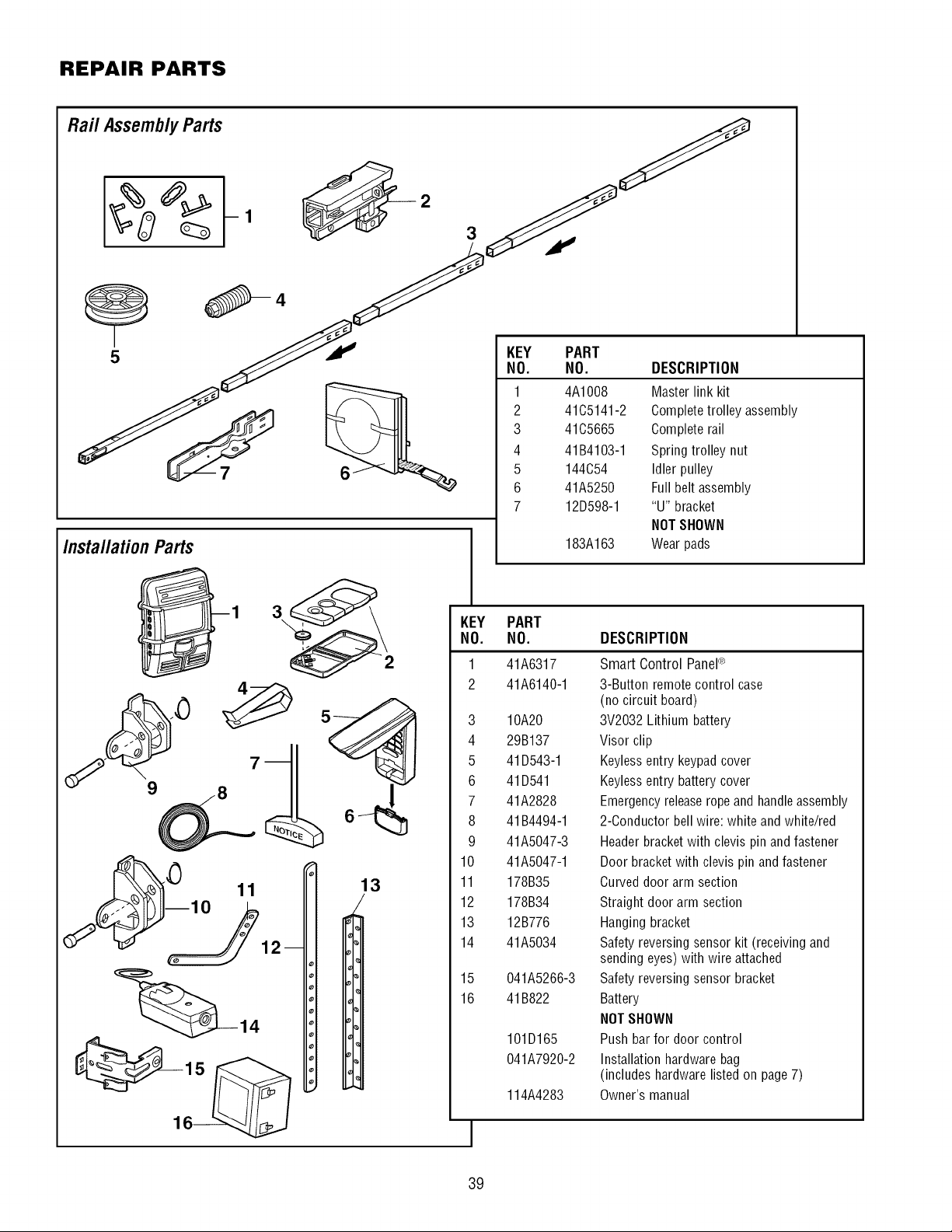
REPAIR PARTS
Rail Assembly Parts S
5 _ J NO. NO. DESCRIPTION
Installation Parts
1
2
3
4A1008
41C5141-2
41C5665
Master link kit
Completetrolley assembly
Complete rail
4
5
6
7
41B4103-1
144C54
41A5250
12D598-1
183A163
KEY PART
NO. NO.
Spring trolley nut
Idler pulley
Full belt assembly
"U" bracket
NOT SHOWN
Wear pads
3
\
13
1
2
41A6317
41A6140-1
3 10A20
4 29B137
5 41D543-1
6 41D541
7 41A2828
8 41B4494-1
9 41A5047-3
10 41A5047-1
11 178B35
12 178B34
13 12B776
14 41A5034
15 041A5266-3
16 41B822
1
101D165
041A7920-2
114A4283
DESCRIPTION
Smart Control PaneP
3-Button remote control case
(no circuit board)
3V2032 Lithium battery
Visor clip
Keyless entry keypad cover
Keyless entry battery cover
Emergencyrelease ropeand handle assembly
2-Conductor bell wire: white and white/red
Header bracket with clevis pin and fastener
Door bracket with clevis pin and fastener
Curved door arm section
Straight door arm section
Hanging bracket
Safety reversing sensor kit (receiving and
sending eyes) with wire attached
Safety reversing sensor bracket
Battery
NOT SHOWN
Push bar for door control
Installation hardware bag
(includes hardware listed on page 7)
Owner's manual
39
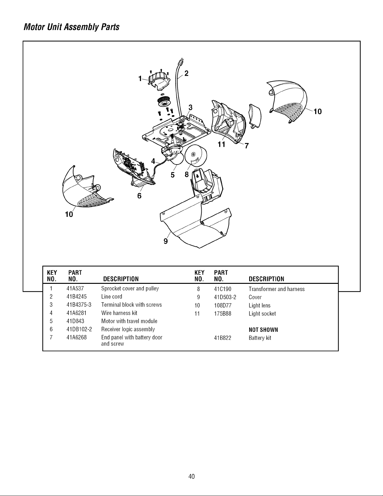
Motor UnitAssemblyParts
10
10
9
KEY
NO.
1
2
3
4
5
6
7
PART
NO. DESCRIPTION
41A537 Sprocketcoverand pulley
41B4245 Linecord
41B4375-3 Terminalblockwith screws
41A6281 Wireharnesskit
41D843 Motorwithtravel module
41DB102-2 Receiverlogicassembly
41A6268 Endpanelwith batterydoor
andscrew
KEY PART
NO. NO.
8 41C190
9 41D503-2
10 108D77
11 175B88
41B822
DESCRIPTION
Transformerandharness
Oover
Lightlens
Lightsocket
NOTSHOWN
Batterykit
40
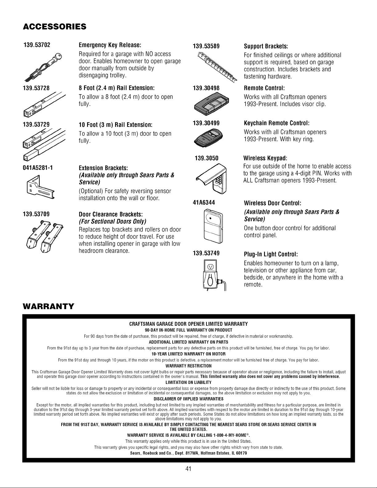
ACCESSORIES
139.53702
139.53728
EmergencyKeyRelease:
Required for a garage with NO access
door. Enableshomeowner to open garage
door manually from outside by
disengaging trolley.
8 Foot(2.4 m) Rail Extension:
To allow a 8 foot (2.4 m) door to open
fully.
139.53589
139.30498
SupportBrackets:
For finished ceilings or where additional
support is required, based on garage
construction. Includes bracketsand
fastening hardware.
RemoteControl:
Works with all Craftsman openers
1993-Present. Includes visor clip.
139.53729
10 Foot(3 m) Rail Extension:
To allow a 10 foot (3 m) door to open
fully.
139.30499
KeychainRemoteControl:
Works with all Craftsman openers
1993-Present. With key ring.
041A5281-1
139.53709
ExtensionBrackets:
(Available onlythrough SearsParts &
Service)
(Optional) For safety reversing sensor
installation onto the wall or floor.
DoorClearanceBrackets:
(For SectionalDoorsOnly)
Replacestop brackets and rollers on door
to reduce height of door travel. For use
when installing opener in garagewith low
headroom clearance.
139.3050
41A6344
139.53749
Wireless Keypad:
For use outside of the home to enableaccess
to the garageusing a 4-digit PIN. Works with
ALL Craftsman openers 1993-Present.
Wireless DoorControl:
(Available only throughSears Parts &
Service)
Onebutton door control for additional
control panel.
Plug-In LightControl:
Enableshomeowner to turn on a lamp,
television or other appliance from car,
bedside, or anywhere in the home with a
remote.
WARRANTY
CRAFTSMAN GARAGE DOOR OPENER LIMITED WARRANTY
90-DAY IN-HOME FULLWARRANTY ON PRODUCT
For 90 days from the date of purchase, this product will be repaired, free of charge, if defective in material or workmanship.
ADDITIONAL LIMITED WARRANTY ON PARTS
From the 91st day up to 3 year from the date of purchase, replacement parts for any defective parts on this product will be furnished, free of charge. You pay for labor.
IO-YEAR LIMITED WARRANTY ON MOTOR
From the 91st day and through 10 years, if the motor on this product is defective, a replacement motor will be furnished free of charge. You pay for labor.
WARRANTY RESTRICTION
This Craftsman Garage Door Opener Limited Warranty does not cover light bulbs or repair parts necessary because of operator abuse or negligence, including the failure to install, adjust
and operate this garage door opener according to instructions contained in the owner's manual. This limited warranly also does nol cover any problems caused by interlerence.
LIMITATION ON LIABILITY
Seller will not be liable for loss or damage to property or any incidental or consequential loss or expense from property damage due directly or indirectly to the use of this product. Some
states do not allow the exclusion or limitation of incidental or consequential damages, so the above limitation or exclusion may not apply to you.
DISCLAIMER OFIMPLIED WARRANTIES
Except for the motor, all implied warranties for this product, including but not limited to any implied warranties of merchantability and fitness for a particular purpose, are limited in
duration to the 91st day through 3-year limited warranty period set forth above. All implied warranties with respect to the motor are limited in duration to the 91st day through 1O-year
limited warranty period set forth above. No implied warranties will exist or apply after such periods. Some States do not allow limitations on how long an implied warranty lasts, so the
above limitations may not apply to you.
FROM THE 918T DAY, WARRANTY SERVICE IS AVAILABLEBYSIMPLY CONTACTINGTHE NEARESTSEARSSTOREOR SEARS SERVICECENTERIN
THE UNITED STATES.
WARRANTY SERVICEIS AVAILABLEBYCALLING 1-80O-4-MY-HOME_L
This warranty applies only while this product is in use in the United States.
This warranty gives you specific legal rights, and you may also have other rights which vary from state to state.
Sears, Roebuck and Co., Dept. 817WA, Hollman Estates, IL 60179
41
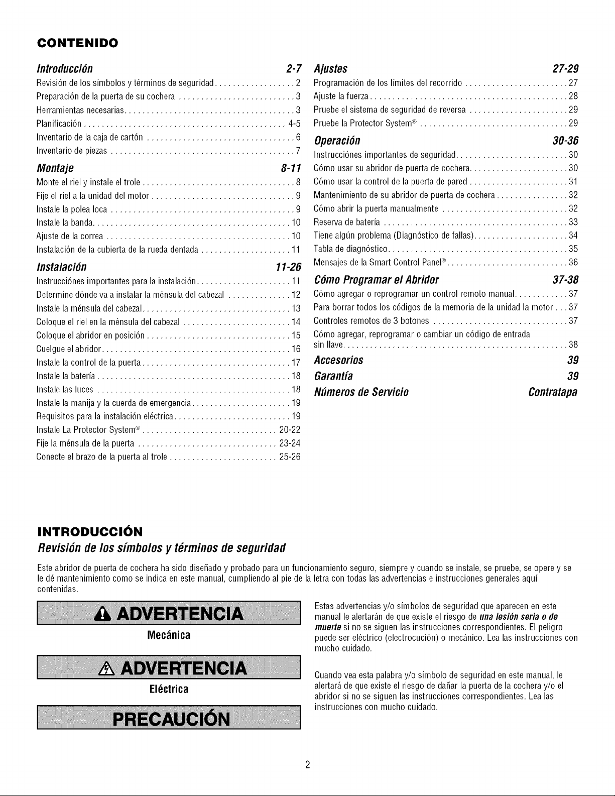
CONTENIDO
Introducci6n 2-7
Revisi6n de los simbolos y t_rminos de seguridad.................. 2
Preparaci6n de la puerta de su cochera .......................... 3
Herramientas necesarias...................................... 3
Planificaci6n ............................................. 4-5
Inventario de la caja de cart6n ................................. 6
Inventario de piezas ......................................... 7
Montaje 8-11
Monte el riel y instale el trole .................................. 8
Fije el riel a la unidad del motor ................................ 9
Instale la polea Ioca ......................................... 9
Instale la banda............................................ 10
Ajuste de la correa ......................................... 10
Instalaci6n de la cubierta de la rueda dentada .................... 11
Instalaci6n 11-26
Instrucci6nes importantes para la instalaci6n ..................... 11
Determine d6nde va a instalar la m_nsula del cabezal .............. 12
Instale la m_nsula del cabezal................................. 13
Coloque el riel en la m_nsula del cabezal ........................ 14
Coloque el abridor en posici6n ................................ 15
Cuelgue el abridor .......................................... 16
Instale la control de la puerta ................................. 17
Instale la bateria ........................................... 18
Instale las luces ........................................... 18
Instale la manija y la cuerda de emergencia ...................... 19
Requisitos para la instalaci6n el_ctrica .......................... 19
Instale La Protector System_ .............................. 20-22
Fije la m_nsula de la puerta ............................... 23-24
Conecte el brazo de la puerta al trole ........................ 25-26
Ajustes 27-29
Programaci6n de los limites del recorrido ....................... 27
Ajuste lafuerza ............................................ 28
Pruebe el sistema de seguridad de reversa ...................... 29
Pruebe la Protector System_ ................................. 29
Operaci6n 30-36
Instrucci6nes importantes deseguridad......................... 30
C6mo usar su abridor de puerta de cochera...................... 30
C6mo usar la control de la puerta de pared ...................... 31
Mantenimiento de su abridor de puerta de cochera ................ 32
C6mo abrir la puerta manualmente ............................ 32
Reserva de bateria ......................................... 33
Tiene alg_n problema (Diagn6stico de fallas) ..................... 34
Tabla de diagn6stico ........................................ 35
Mensajes de la Smart Control PaneP ........................... 36
C6moProgramarel Abridor 37-38
C6mo agregar o reprogramar un control remoto manual............ 37
Para borrar todos los c6digos de la memoria de la unidad la motor... 37
Controles remotos de 3 botones .............................. 37
C6mo agregar, reprogramar o cambiar un c6digo de entrada
sin Ilave.................................................. 38
Accesorios 39
Garantia 39
N#meros de Servicio Contratapa
INTRODUCCION
Revisi6n de/os simbo/osy t_rminosde seguridad
Este abridor de puerta de cochera ha sido diseSadoy probado para un funcionamiento seguro, siempre y cuando se instale, se pruebe, se opere y se
le d_ mantenimiento como se indica en este manual, cumpliendo al pie de la letra con todas las advertencias e instrucciones generalesaqui
contenidas.
Mecanica
El_ctrica
Estas advertencias y/o simbolos de seguridad que aparecen en este
manual le alertar_.nde que existe el riesgo de una lesi6n seria e de
muerte si no se siguen las instrucciones correspondientes. El peligro
puede ser el6ctrico (electrocuci6n) o mec_.nico.Lea las instrucciones con
mucho cuidado.
Cuando vea esta palabra y/o simbolo de seguridad en este manual, le
alertar_,de que existe el riesgo de da_ar la puerta de la cocheray/o el
abridor si no se siguen las instrucciones correspondientes. Lea las
instrucciones con mucho cuidado.
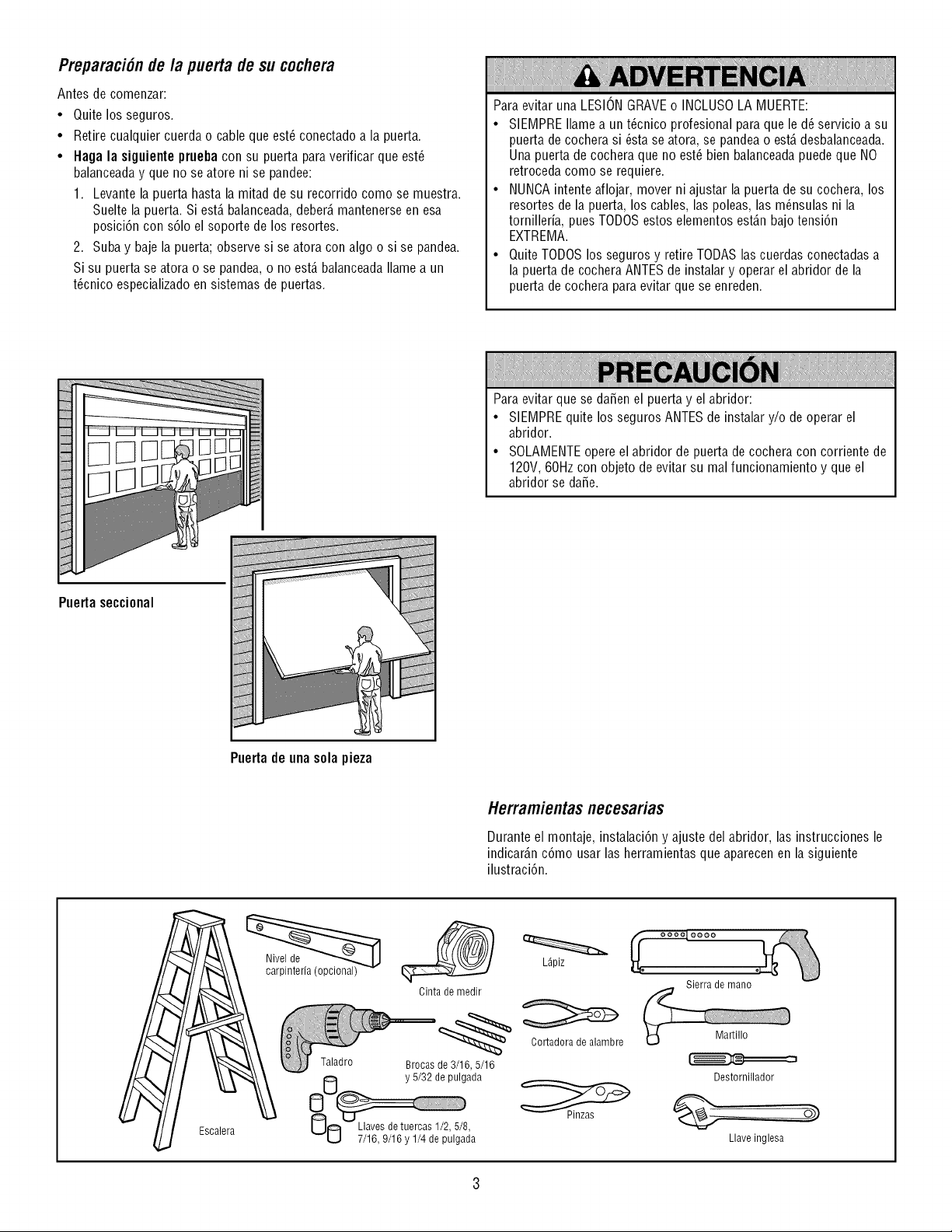
Preparaci6nde la puerta de su cochera
Antes de comenzar:
• Quite los seguros.
• Retire cualquier cuerda o cable que est_ conectado a la puerta.
• Haga la siguiente prueba con su puerta para verificar que est_
balanceaday que no se atore ni se pandee:
1. Levante la puerta hasta la mitad de su recorrido como se muestra.
Suelte la puerta. Si est,. balanceada,deber_,mantenerse en esa
posici6n con s61oel soporte de los resortes.
2. Suba y baje la puerta; observe si se atora con algo o si se pandea.
Si su puerta se atora o se pan@a, o no est,. balanceadaIlame a un
t@nico especializadoen sistemas de puertas.
Para evitar una LESIONGRAVEo INCLUSOLA MUERTE:
• SIEMPREIlame a un t@nico profesional para que le d_ servicio a su
puerta de cochera si _sta se atora, se pandea o est,. desbalanceada.
Una puerta de cochera que no est_ bien balanceadapuede que NO
retroceda como se requiere.
• NUNCAintente aflojar, mover ni ajustar la puerta de su co@era, los
resortes de la puerta, los cables, las poleas, las m_nsulas ni la
tornilleria, puesTODOSestos elementos est_.nbajo tensi6n
EXTREMA.
• Quite TODOSlos seguros y retire TODASlas cuerdas conectadas a
la puerta de cochera ANTESde instalar y operar el abridor de la
puerta de cochera para evitar que se enreden.
Para evitar que se daSen el puerta y el abridor:
• SIEMPREquite los seguros ANTESde instalar y/o de operar el
abridor.
• SOLAMENTEopere el abridor de puerta de cochera con corriente de
120V, 60Hz con objeto de evitar su mal funcionamiento y que el
abridor se daSe.
Puertaseccional
Puertade unasola pieza
Herramientasnecesarias
Durante el montaje, instalaci6n y ajuste del abridor, las instrucciones le
indicar_.nc6mo usar las berramientas que aparecen en la siguiente
ilustraci6n.
Escalera
Cinta de medir
Taladro Brocas de 3/16, 5/16
y 5/32 de pulgada
NO 7/16, 9/16 y 1/4 de p'ulgada
L_piz
Oortadora de alambre
Sierra de mano
Martillo
Destornillador
...... O_
Llave inglesa
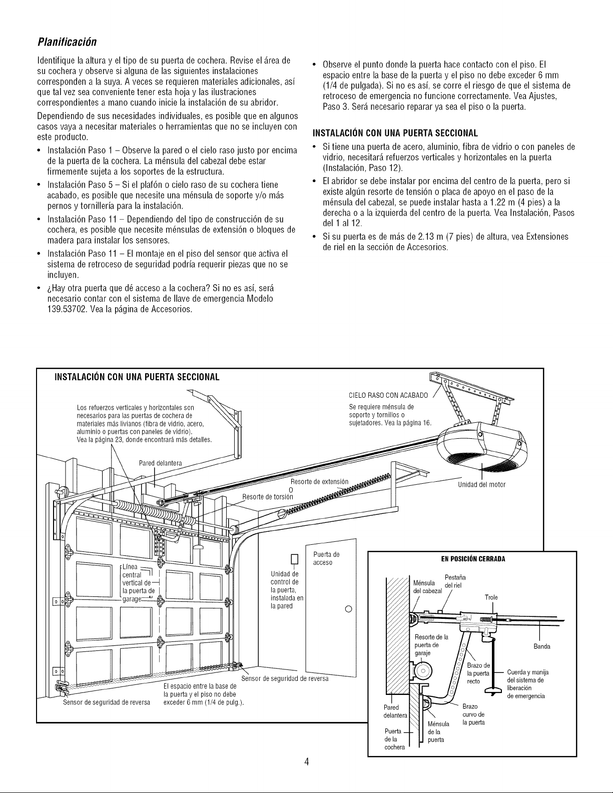
Planificaci6n
Identifique la altura y el tipo de su puerta de cochera. Reviseel _.reade
su cochera y observe si alguna de las siguientes instalaciones
corresponden a la suya. A veces se requieren materiales adicionales, asi
que tal vez sea convenientetener esta hoja y las ilustraciones
correspondientes a mano cuando inicie la instalaci6n de su abridor.
Dependiendo de sus necesidades individuales, es posible queen algunos
casos vaya a necesitar materiales o herramientas que no se incluyen con
este producto.
• Instalaci6n Paso 1 - Observe la pared o el cielo raso justo por encima
de la puerta de la cochera. La m_nsula del cabezaldebe estar
firmemente sujeta a los soportes de la estructura.
• Instalaci6n Paso 5 - Si el plaf6n o cielo raso de su cochera tiene
acabado, es posible que necesite una m_nsula de soporte y/o m_.s
pernos y tornilleria para la instalaci6n.
• Instalaci6n Paso 11 - Dependiendodel tipo de construcci6n de su
cochera, es posible que necesite m_nsulas de extensi6n o bloques de
madera para instalar los sensores.
• Instalaci6n Paso 11 - El montaje en el piso del sensor que activa el
sistema de retroceso de seguridad podria requerir piezas que no se
incluyen.
• &Hayotra puerta que d_ acceso a la cochera? Si no es asi, ser_.
necesario contar con el sistema de Ilave de emergencia Modelo
139.53702. Vea la p_.ginade Accesorios.
Observe el punto donde la puerta hace contacto con el piso. El
espacio entre la basede la puerta y el piso no debe exceder 6 mm
(1/4 de pulgada). Si no es asi, se corre el riesgo de que el sistema de
retroceso de emergencia no funcione correctamente. Vea Ajustes,
Paso 3. Ser_.necesario reparar ya sea el piso o la puerta.
INSTALACIONCON UNAPUERTASECCIONAL
• Si tiene una puerta de acero, aluminio, fibra de vidrio o con paneles de
vidrio, necesitar_,refuerzos verticales y horizontales en la puerta
(Instalaci6n, Paso 12).
• El abridor se debe instalar por encima del centro de la puerta, pero si
existe alg_n resorte de tensi6n o placa de apoyo en el paso de la
m_nsula del cabezal, se puede instalar hasta a 1.22 m (4 pies) a la
derecha o a la izquierda del centro de la puerta. Vea Instalaci6n, Pasos
del 1 al 12.
• Si su puerta es de m_.sde 2.13 m (7 pies) de altura, vea Extensiones
de riel en la secci6n de Accesorios.
INSTALACIONCONUNAPUERTASECCIONAL
Los refuerzos verticales y horizontales son
necesarios para las puertas de cochera de
materiales m_s livianos (fibra de vidrio, acero,
aluminio o puertas con paneles de vidrio).
Vea la pAgina 23, donde encontrarA mAs detalles.
Pared delantera
Resorte de extensi6n
0
Resorte de torsi6n
CIELO RASO CONACABADO
Se requiere mdnsula de
soporte y tornillos o
sujetadores. Vea la p_gina 16.
Unidad del motor
Linea
central-ql I
vertical de
la puerta de I
g
Unidad de
control de
la puerta,
instalada en
la pared
Puerta de
acceso
0
Sensor de seguridad de reversa
Sensor de seguridad de reversa_
El espacio entre la base de
la puerta y el piso no debe
exceder 6 mm (1/4 de pulg.).
EN POSICIONCERRADA
Pesta_a
Mensula del riel
Trole
Banda
Mensula
de la
puerta
Brazo
curvode
la pueda
Cuerday manija
del sistemade
liberaci6n
de emergencia
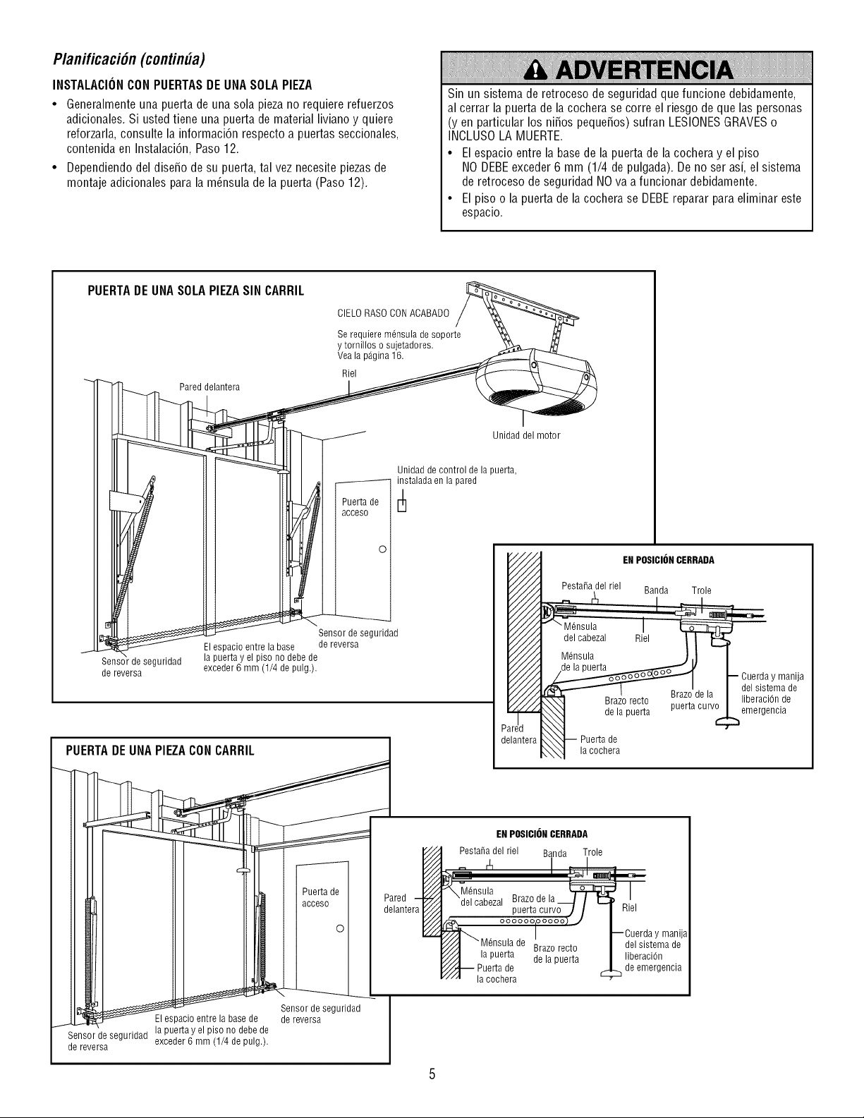
Planificaci6n (continUa)
INSTALACIONCON PUERTASDE UNASOLAPIEZA
• Generalmente una puerta de una sola piezano requiere refuerzos
adicionales. Si usted tiene una puerta de material liviano y quiere
reforzarla, consulte la informaci6n respecto a puertas seccionales,
contenida en Instalaci6n, Paso 12.
• Dependiendo del dise_o de su puerta, tal vez necesite piezas de
montaje adicionales para la m6nsula de la puerta (Paso 12).
Sin un sistema de retroceso de seguridad que funcione debidamente,
al cerrar la puerta de la cochera se corre el riesgo de que las personas
(yen particular los ni_os peque_os) sufran LESIONESGRAVESo
INCLUSOLA MUERTE.
• El espacio entre la basede la puerta de la cochera y el piso
NO DEBEexceder 6 mm (1/4 de pulgada). De no ser asi, el sistema
de retroceso de seguridad NO va a funcionar debidamente.
• El piso o la puerta de la cochera se DEBEreparar para eliminar este
espacio.
PUERTADE UNA SOLAPIEZASIN CARRIL
\
Sensordeseguridad
de reversa
Pared delantera
CIELO RASO CONACABADO
Se requiere m6nsula de soporte
y tornillos o sujetadores.
Vea la pAgina 16.
Riel
Puerta de
acceso
ol
Sensor de seguridad
El espacio entre la base de reversa
la puertayel piso no debe de
exceder 6 mm (1/4 de pulg.).
eseour,dadI
Elespacio entre la base de de reversa I
................................Sensor de seguridad La,pue;ay.eLpls_°In°deb,ede
de reversa u^vuu_ u mm it/'4 uu ,uuty. b |
]
Unidad del motor
Unidad de control de la puerta,
instalada en la pared
,i/11
/////
,,'///.,
/////
/////
/////
,,'///.,
/////
/////
/////
,,'///.,
/////
/////
/////
,,'///.,
/////
/////
/////
,,'///.,
/////
/////
/////
,,'///.,
/////
iiHfl
lantera
ENPOSICIONCERRADA
Pesta_a del riel Banda Trole
I
'- " ?_Ja
_ Puerta de
_N.._I lacochera
EN POSICIONCERRADA
Pesta_a del riel Banda Trole
Brazo recto
la puerta de la puerta
Puerta de
la cochera
Riel
manija
del sistema de
liberaciOn
de emergencia
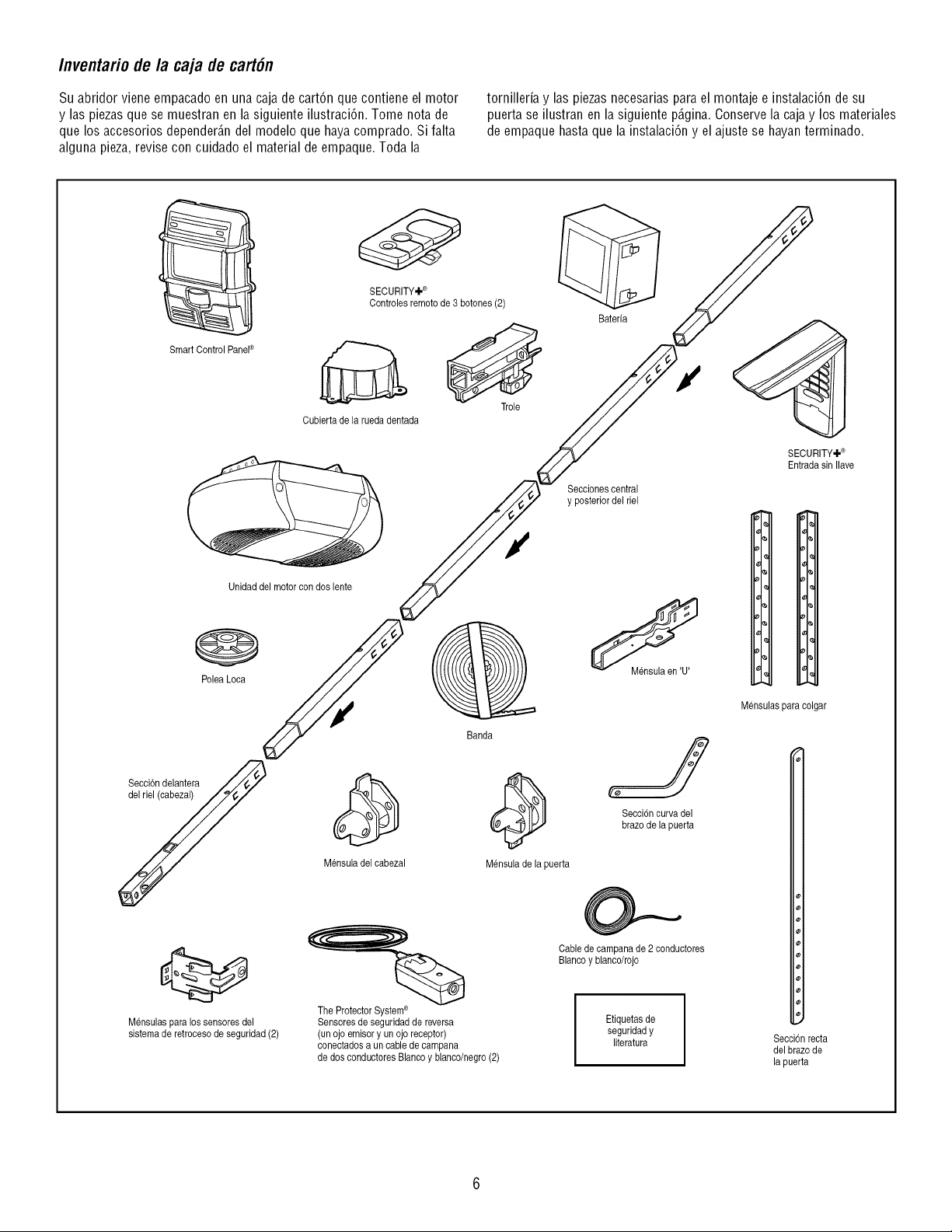
Inventario de la caja de cart6n
Su abridor viene empacado en una caja de cart6n que contiene el motor
y las piezasque se muestran en la siguiente ilustraci6n. Tome nota de
que los accesorios depender_.ndel modelo que hayacomprado. Si falta
alguna pieza, revise con cuidado el material de empaque. Toda la
tornilleria y las piezas necesariaspara el montaje e instalaci6n de su
puerta se ilustran en la siguiente p_.gina.Conservela caja y los materiales
de empaque hasta que la instalaci6n y el ajuste se hayan terminado.
Smart ControlPanel®
SECURITY÷®
Controles remotode 3 botches (2)
Cubierta de la ruedadentada
Trole
Bateria
Seccionescentral
y posteriordel riel
Unidaddel motorcon dos lente
@
PoleaLoca
Secci0ndelantera
del riel (cabezal)
Mensuladel cabezal
Banda
Mensulade la puerta
Secci6ncurva del
brazode la puerta
Mensulaspara lossensoresdel
sistemade retrocesode seguridad (2)
The ProtectorSystem®
Sensoresde seguridadde reversa
(un ojo emisor y un ojo receptor)
eoneetadosa uncable de campana
de dos conductoresBlanco y blanco/negro(2)
O--
Cablede campanade 2 conductores
Blancoy blanco/rojo
Etiquetasde
seguridady
literatura
SECURITY÷®
Entrada sin llave
%
I,
%
%
I°
9°
Mensulaspara colgar
Secci6nrecta
del brazo de
la puerta
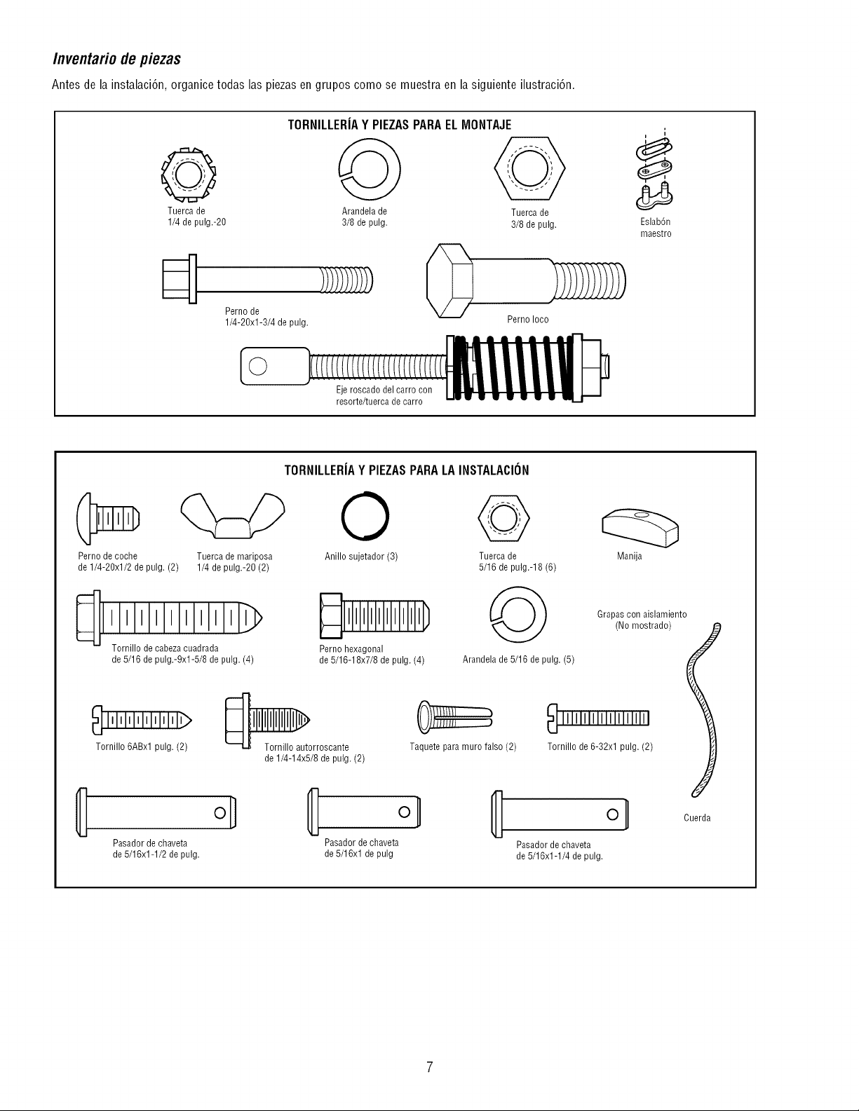
Inventario de piezas
Antes de la instalaci6n, organice todas las piezas en grupos como se muestra en la siguiente ilustraci6n.
TORNILLERIAY PIEZASPARAELMONTAJE
Tuerca de Arandela de Tuerca de
1/4 de pulg.-20 3/8 de pulg. 3/8 de pulg.
Perno de
1/4-20xl-3/4 de pulg. Perno Ioco
Ejeroscado del carro con
resorte/tuerca de carro
i
i
Eslab6n
maestro
TORNILLERIAY PIEZASPARALAINSTALACION
Perno de coche Tuerca de mariposa
de 1/4-20xl/2 de pulg. (2) 1/4 de pulg.-20 (2)
O
Anillo sujetador (3) Tuerca de
5/16 de pulg.-18 (6)
'Zor'nio'd 'ca,lz,'>
de 5/16 de pulg.-9xl-5/8 de pulg. (4)
Perno hexagonal
de 5/16-18x7/8 de pulg. (4) Arandela de 5/16 de pulg. (5)
lllMIMlllllllllll
Tornillo 6ABxl pulg. (2)
Pasador de chaveta
de 5/16x1-1/2 de pulg.
_orroscante
de 1/4-14x5/8 de pulg. (2)
Taquete para muro falso (2)
Pasador de chaveta
de 5/16xl de pulg
Manija
Grapas con aislamiento
(No mostrado)
gornillo de 6-32xl pulg. (2)
oH
Cuerda
Pasador de chaveta
de 5/16x1-1/4 de pulg.
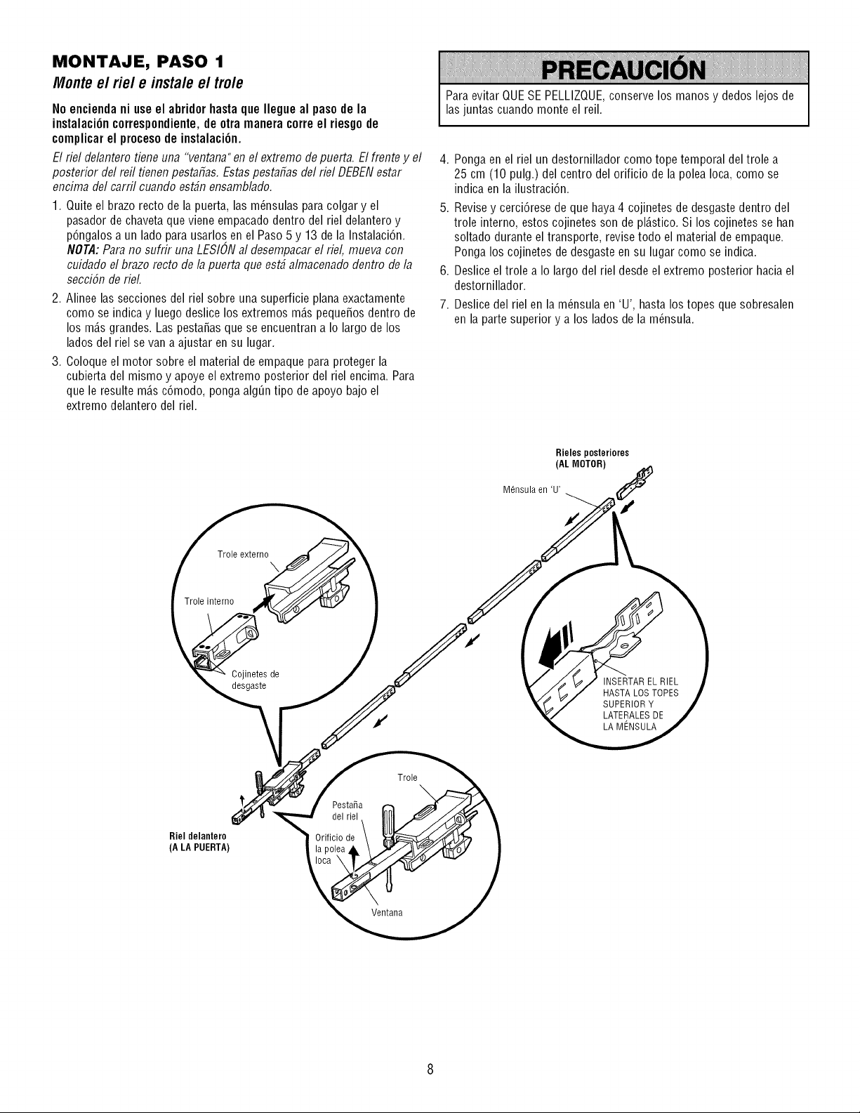
MONTAJE, PASO 1
Monte e/fie/e insta/e e/tro/e
No encienda ni use el abridor hasta que Ilegue al paso de la
instalaci6n correspondiente,de otra manera corre el riesgo de
complicar el proceso de instalaci6n.
El riel delantero tiene uiTa"veiTtaiTa"ei7el extremo de puerta. El frente y el
posterior del reil tienen pestafias. Estaspestafias del riel DEBENestar
encima del carril cuando est_n ensamblado.
1. Quite el brazo recto de la puerta, las m_nsulas para colgar y el
pasador de chavetaque viene empacado dentro del riel delantero y
p6ngalos a un lado para usarlos en el Paso 5 y 13 de la Instalaci6n.
NOTA:Para no sufrir una LESIONal desempacar el riel, mueva con
cuidado el brazo recto de la puerta que est_ almacenado dentro de la
seccibn de rieL
2. Alinee las secciones del riel sobre una superficie plana exactamente
como se indica y luego deslice los extremos m_.speque_os dentro de
los m_.sgrandes. Las pesta_as que se encuentran a Io largo de los
lados del riel se van a ajustar en su lugar.
3. Coloque el motor sobre el material de empaque para proteger la
cubierta del mismo y apoye el extremo posterior del riel encima. Para
que le resulte m_.sc6modo, ponga alg_n tipo de apoyo bajo el
extremo delantero del riel.
Para evitar QUESE PELLIZQUE,conserve los manos y dedos lejos de
las juntas cuando monte el reil.
4. Ponga en el riel un destornillador como tope temporal del trole a
25 cm (10 pulg.) del centro del orificio de la polea Ioca, como se
indica en la ilustraci6n.
5. Revisey cerci6rese de que haya4 cojinetes de desgaste dentro del
trole interno, estos cojinetes son de pl_.stico.Si los cojinetes se han
soltado durante el transporte, revise todo el material de empaque.
Ponga los cojinetes de desgaste en su lugar como se indica.
6. Deslice el trole a Io largo del riel desde el extremo posterior hacia el
destornillador.
7. Deslice del riel en la m_nsula en 'U', hasta los topes que sobresalen
en la parte superior y a los lados de la m_nsula.
Rieles posteriores
(AL MOTOR)
M6nsula en 'U'
Trole externo
\
Trole interno
Cojinetes de
desgaste
INSERTAR ELRIEL
HASTA LOS TOPES
SUPERIORY
LATERALESDE
LA MENSULA
Riel delantero
(A LA PUERTA)
PestaRa
del riel
Orificio de
Trole
\
Ventana
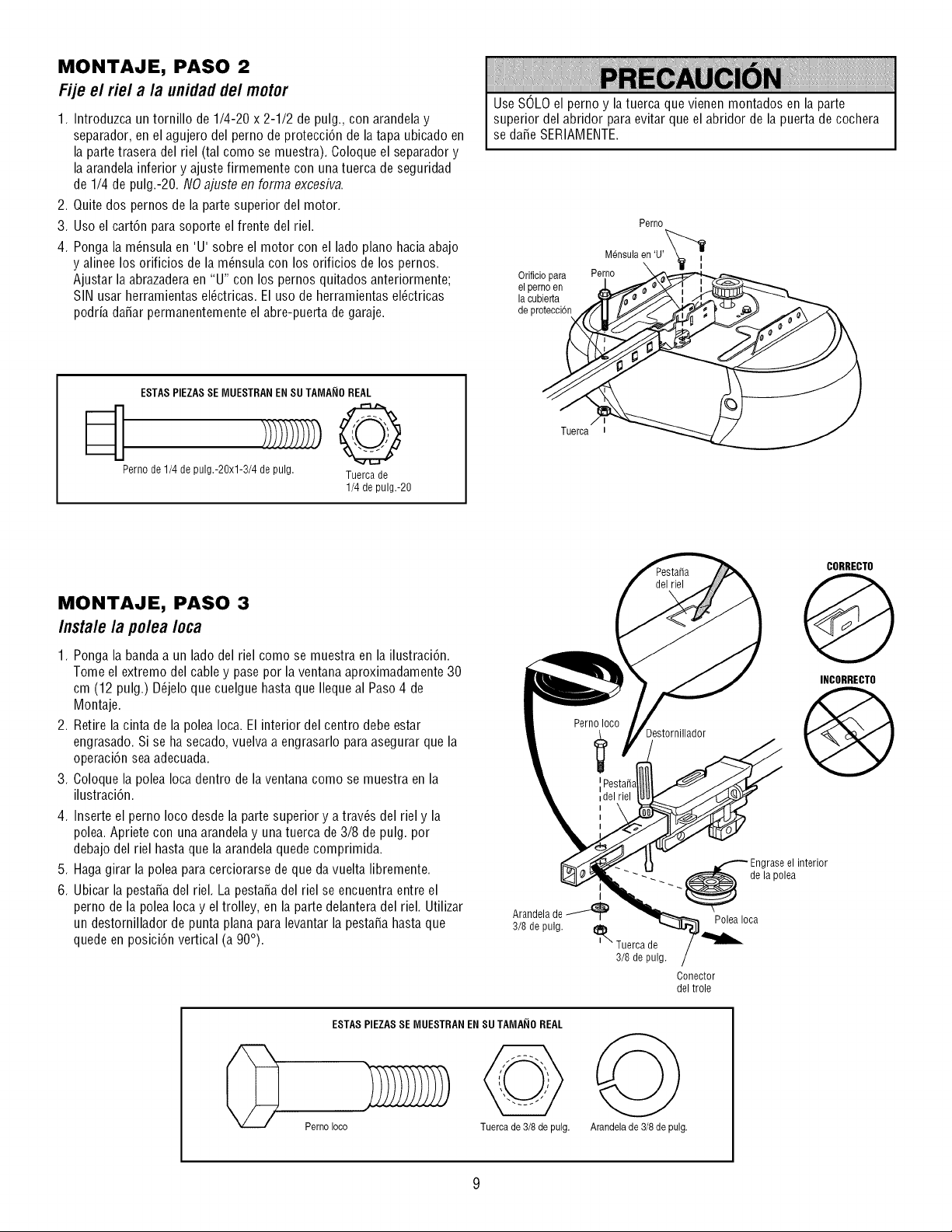
MONTAJE, PASO 2
Fije el riel a la unidadde/motor
1. Introduzca un tornillo de 1/4-20 x 2-1/2 de pulg., con arandelay
separador, en el agujero del perno de protecci6n de latapa ubicado en
la partetrasera del riel (tal como se muestra). Coloque el separador y
la arandela inferior y ajuste firmemente con una tuerca de seguridad
de 1/4 de pulg.-20. NO ajuste en forma excesiva.
2. Quite dos pernos de la parte superior del motor.
3. Uso el cart6n para soporte el frente del riel.
4. Ponga la m6nsula en 'U' sobre el motor con el lado piano hacia abajo
y alinee los orificios de la m_nsula con los orificios de los pernos.
Ajustar la abrazaderaen "U" con los pernos quitados anteriormente;
SIN usar herramientas el_ctricas. El uso de herramientas el_ctricas
podria daSar permanentemente el abre-puerta de garaje.
Use SOLO el perno y la tuerca que vienen montados en la parte
superior del abridor para evitar que el abridor de la puerta de cochera
se da_e SERIAMENTE.
Orificiopara
el pernoen
la cubierta
de proteccbn
Perno
Uensula e._'U'_lll
Perno
ESTAS PIEZASSE MUESTRAN ENSU TAMANOREAL
Perno de 1/4 de pulg.-20xl-3/4 de pulg. Tuerca de
1/4 de pulg.-20
Tuerca
MONTAJE, PASO 3
Instale la polea Ioca
1. Ponga la bandaa un lado del riel como se muestra en la ilustraci6n.
Tome el extremo del cable y pase por la ventana aproximadamente 30
cm (12 pulg.) D_jelo que cuelgue hasta que Ileque al Paso 4 de
Montaje.
2. Retire la cinta de la polea Ioca. El interior del centro debe estar
engrasado. Si se ha secado, vuelva a engrasarlo para asegurar que la
operaci6n sea adecuada.
3. Coloque la polea Ioca dentro de la ventana como se muestra en la
ilustraci6n.
4. Inserte el perno Ioco desde la parte superior y a trav6s del riel y la
polea. Apriete con una arandela y una tuerca de 3/8 de pulg. por
debajo del riel hasta que laarandela quede comprimida.
5. Haga girar la polea para cerciorarse de que da vuelta libremente.
6. Ubicar la pestaSadel riel. La pestaSadel riel se encuentra entre el
perno de la polea Ioca y el trolley, en la parte delantera del riel. Utilizar
un destornillador de punta plana para levantar la pestaSahasta que
quede en posici6n vertical (a 90°).
I
Arandela de
3/8 de pulg.
ESTAS PIEZASSE MUESTRAN EN SUTAMANO REAL
Perno Ioco
Tuerca de 3/8 de pulg.
Destornillador
CORRECTO
Q
INCORRECTO
Engrase el interior
-.. _. _de la polea
Polea Ioca
_ Tuerca de
3/8 de pulg.
Conector
del trole
Arandela de 3/8de pulg.
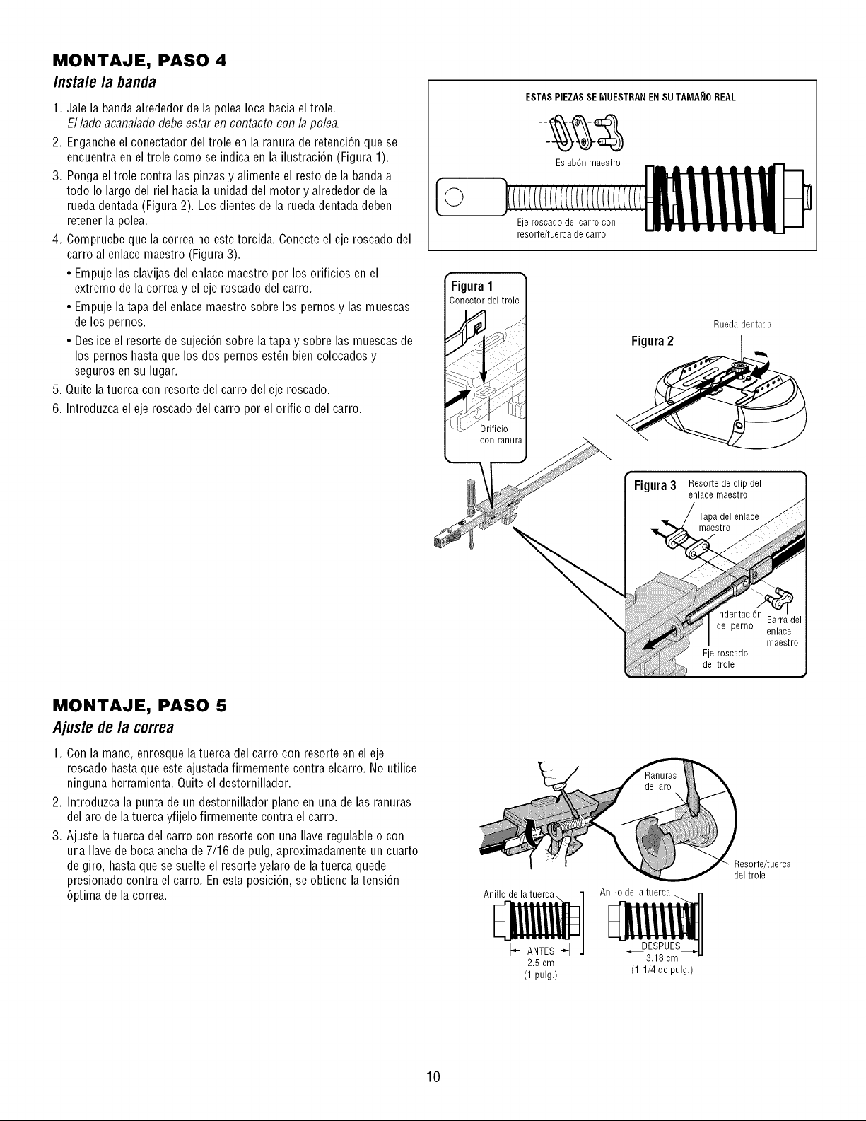
MONTAJE, PASO 4
/nsta/e /a banda
1. Jale la banda alrededor de la polea Ioca hacia el trole.
El lado acanalado debe estar en contacto con la pole&
2. Enganche el conectador del trole en la ranura de retenci6n que se
encuentra en eltrole como se indica en la ilustraci6n (Figura 1).
3. Ponga el trole contra las pinzas y alimente el resto de la bandaa
todo Io largo del riel hacia la unidad del motor y alrededor de la
rueda dentada (Figura 2). Los dientes de la rueda dentada deben
retener la polea.
4. Compruebe que la correa no estetorcida. Conecte el eje roscado del
carro al enlace maestro (Figura 3).
• Empuje las clavijas del enlace maestro por los orificios en el
extremo de la correa y el eje roscado del carro.
• Empuje la tapa del enlace maestro sobre los pernos y las muescas
de los pernos.
• Desliceel resorte de sujeci6n sobre la tapa y sobre las muescas de
los pernos hasta que los dos pernos est_n bien colocados y
seguros en su lugar.
5. Quite la tuerca con resorte del carro del eje roscado.
6. Introduzca el eje roscado del carro por el orificio del carro.
ESTAS PIEZASSE IVIUESTRANEN SU TAIVIA_IOREAL
Eslab6nmaestro
Eje roscado del carro con
resorte/tuerca de carro
f
Figura 1
Conector del trole
conranura
Figura2
Figura3
Rueda dentada
Resorte de clip del
enlace maestro
Tapa del enlace
maestro
del trole
MONTAJE, PASO 5
Ajuste de la correa
1. Con la mano, enrosque la tuerca del carro con resorte en el eje
roscado hasta que este ajustadafirmemente contra elcarro. No utilice
ninguna herramienta. Quite el destornillador.
2. Introduzca la punta de un destornillador piano en una de las ranuras
del aro de la tuerca yfijelo firmemente contra el carro.
3. Ajuste latuerca del carro con resorte con una Ilave regulable o con
una Ilave de boca ancha de 7/16 de pulg, aproximadamente un cuarto
de giro, hasta que se suelte el resorte yelaro de latuerca quede
presionado contra el carro. En esta posici6n, se obtiene la tensi6n
6ptima de la correa.
Anillo de la tuerca.
I-ANTES--I
2.5 cm
(1 pulg.)
_DESPUES_I
3.18 cm "
(1-1/4 de pulg.)
Resorte/tuerca
del trole
10
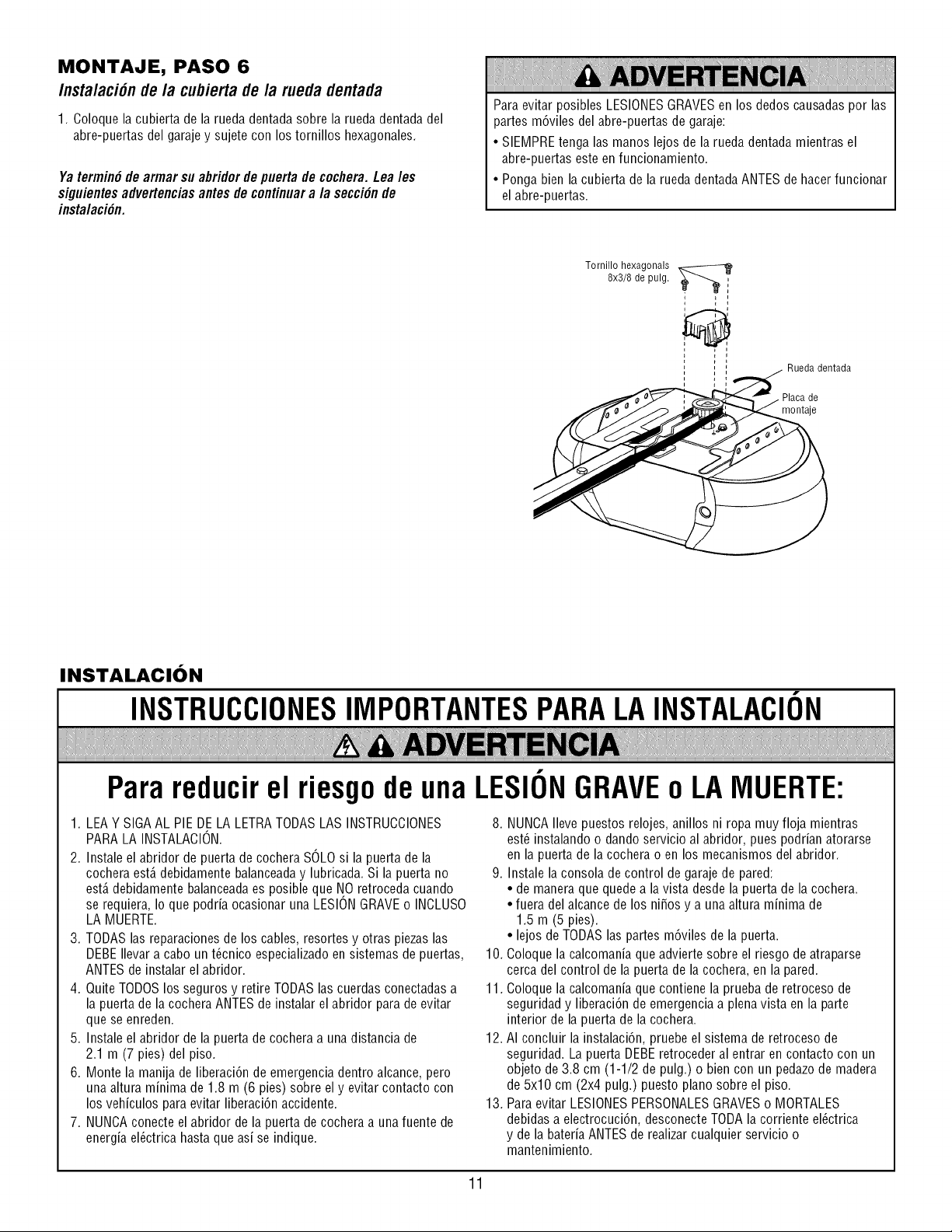
MONTAJE, PASO 6
Insta/aci6n de/a cubiertade la rueda dentada
1. Ooloque la cubierta de la rueda dentada sobre la rueda dentada del
abre-puertas del garajey sujete con los tornillos hexagonales.
Yatermin#de armarsuabridordepuertade cochera.Leales
siguientesadvertenciasantesdecontinuara la secci#nde
instalaci#n.
Para evitar posibles LESIONESGRAVESen los dedos causadaspor las
partes m6viles del abre-puertas de garaje:
• SIEMPREtenga las manos lejos de la rueda dentada mientras el
abre-puertas este en funcionamiento.
• Ponga bien la cubierta de la rueda dentada ANTES de hacer funcionar
el abre-puertas.
Tornillo hexagonals
8x3/8 de pulg. I
i
i
Rueda dentada
Placa de
montaje
INSTALACION
INSTRUCCIONESIMPORTANTESPARALAINSTALACION
Para reducirel riesgode una LESIONGRAVEo LAMUERTE:
1. LEA Y SIGA AL PIE DE LA LETRATODASLAS INSTRUCCIONES
PARA LA INSTALACION.
2. Instale el abridor de puerta de cochera SOLOsi la puerta de la
cochera est,. debidamente balanceaday lubricada. Si la puerta no
est,. debidamente balanceadaes posible que NO retroceda cuando
se requiera, Io que podria ocasionar una LESIONGRAVEo INCLUSO
LA MUERTE.
3. TODAS las reparaciones de los cables, resortes y otras piezas las
DEBE Ilevara cabo un t_cnico especializado en sistemas de puertas,
ANTESde instalar el abridor.
4. Quite TODOSlos seguros y retire TODASlas cuerdas conectadas a
la puerta de la cochera ANTES de instalar el abridor para de evitar
que se enreden.
5. Instale el abridor de la puerta de cochera a una distancia de
2.1 m (7 pies) del piso.
6. Monte la manija de liberaci6n de emergencia dentro alcance, pero
una altura minima de 1.8 m (6 pies) sobre el y evitar contacto con
los vehiculos para evitar liberaci6n accidente.
7. NUNCAconecte el abridor de la puerta de cochera a una fuente de
energia el_ctrica hasta que asi se indique.
8. NUNCAIleve puestos relojes, anillos ni ropa muy floja mientras
est_ instalando o dando servicio al abridor, pues podrian atorarse
en la puerta de la cochera o en los mecanismos del abridor.
9. Instale la consola de control de garaje de pared:
• de manera que quede a la vista desde la puerta de la cochera.
• fuera del alcance de los ni_os y a una altura minima de
1.5 m (5 pies).
• lejos de TODAS las partes m6viles de la puerta.
10. Coloque la calcomania que advierte sobre el riesgo de atraparse
cerca del control de la puerta de la cochera, en la pared.
11. Coloque la calcomania que contiene la prueba de retroceso de
seguridad y liberaci6n de emergencia a plena vista en la parte
interior de la puerta de la cochera.
12. AI concluir la instalaci6n, pruebe el sistema de retroceso de
seguridad. La puerta DEBEretroceder al entrar en contacto con un
objeto de 3.8 cm (1-1/2 de pulg.) o bien con un pedazode madera
de 5x10 cm (2x4 pulg.) puesto piano sobre el piso.
13. Para evitar LESIONESPERSONALESGRAVESo MORTALES
debidas a electrocuci6n, desconecte TODAla corriente el_ctrica
y de la bateria ANTESde realizar cualquier servicio o
mantenimiento.
11
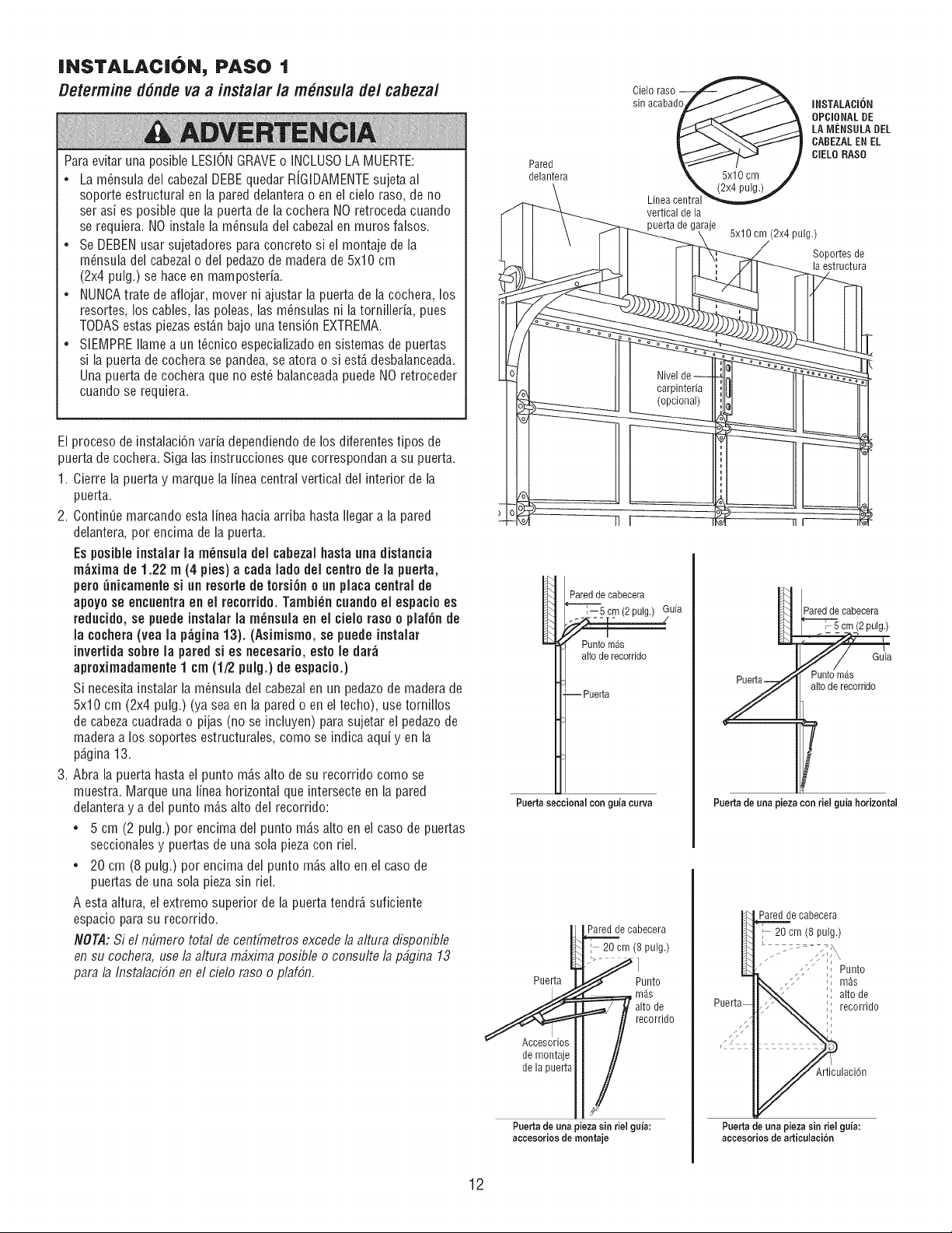
INSTALACI6N, PASO 1
Determined#ndevaa instalarla m nsulade/cabezal
Para evitar una posible LESIONGRAVEo INCLUSOLA MUERTE:
• La m_nsula del cabezalDEBEquedar RiGIDAMENTEsujeta al
soporte estructura[ en la pared deiantera o en ei cieio raso, de no
ser as[ es posible que la puerta de la cochera NO retroceda cuando
se requiera. NO instaie la m6nsula dei cabezalen muros falsos.
• Se DEBENusar sujetadores para concrete si el montaje de la
m_nsula del cabezal o del pedazode maderade 5x10 cm
(2x4 pulg.) se hace en mampostefia.
• NUNCAtrate de aflojar, mover ni ajustar la puerta de la cochera, los
resortes, los cables, las poleas, las m_nsuias ni la torniileria, pues
TODASestas piezasest_.nbajo unatensi6n EXTREMA.
• SIEMPREIlame a un t_cnico especializadoen sistemas de puertas
si la puerta de cochera se pandea, se atora o si est,, desbalanceada.
Una puerta de cochera que no est_ balanceadapuede NO retroceder
cuando se requiera.
El proceso de instalaci6n varia dependiendo de los diferentes tipos de
puerta de cochera. Siga las instrucciones que correspondan a su puerta.
1. Cierre la puerta y marque la linea central vertical dei interior de la
puerta.
2. ContinUemarcando esta linea hacia arriba hasta Ilegar a la pared
delantera, per encima de la puerta.
Es pesible [nstalar la m_nsula del cabezal hasta una distancia
m_ix[made 1.22 m (4 pies) a cada lade del centre de la puerta,
pete tinicamente si tin reserte de tersi6n e [in plata central de
apoye se encuentra en el recerfido. Tambi_n cuande el espacio es
reducide, se puede instalar la m_nsula en el cielo raso e plaf6n de
la cochera (yea la p_gina 13). (Asimismo, se puede instalar
invertida sobre la pared si es necesafio, esto le dar_
apreximadamente 1 cm (1/2 pulg.) de espacio.)
Si necesita instaiar la m_nsula dei cabezal en un pedazode maderade
5x10 cm (2x4 pulg.) (ya sea en la pared o en el techo), use tornillos
de cabezacuadrada o pijas (no se incluyen) para sujetar ei pedazo de
madera a los soportes estructurales, come se indica aqu[ yen la
p_.gina13.
3. Abra la puerta hasta el punto m_,salto de su recorrido come se
muestra. Marque una i[nea horizontal que intersecte en la pared
delantera y a dei punto m_,salto dei recorrido:
• 5 cm (2 pulg.) per encima del punto m6,salto en el case de puertas
seccionales y puertas de una sola pieza con riel.
• 20 cm (8 pulg.) per encima del punto m6,salto en el case de
puertas de una sola piezasin riei.
A esta altura, el extreme superior de la puerta tendr_ suficiente
espacio para su recorrido.
NOT,d: Si el mimero total de centfmetros excede la altura disponible
en su cochera, use la altura m_xima posible o consulte la p_gina 13
para la Instalaci6n en el cielo raso o plaf6n.
Cielo raso
sin acabado
Pared
delantera
vertical de la
puerta de garaje
Pared decabecera
--5 em (2pulg.)
Puntomas
altode recorrido
Puertaseccional conguia curva
Fc e cabecera
m (8 pulg.)
_7
Puerta Punto
Accesorios
demontaie
de la puerta
Puertade una pieza sin riel guia:
accesorios de montaje
INSTALACION
OPCIONAL DE
LA MI_NSULA DEL
CABEZALEN EL
CiEL0 RAS0
5x10 cm (2x4 pulg.)
Soportes de
la estructura
H
Y
Pared de cabecera
era_(2pulg.)
Puntomas
altoderecorrido
T
Puertade una pieza con rio[ guia horizontal
Puerta
Pared de cabecera
20 cm (8 pulg.)
Puertade una piezasin riel guia:
accesorios de articulaci6n
12
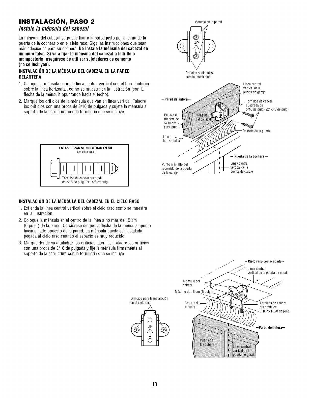
INSTALACION, PASO 2
Insta/e /a m_nsu/ade/cabeza/
La m_nsula del cabezal se puede fijar a la pared justo por encima de la
puerta de la cochera o en el cielo raso. Siga las instrucciones que sean
m_.sadecuadas parasu cochera. No instale la m_nsula del cabezal en
un muro falso. Si va a fijar la m_nsula del cabezal a ladrillo o
mamposteria, asegzirese de utilizar sujetadoresde cemento
(no se incluyen).
INSTALACIONDE LA MENSULADEL CABEZALEN LA PARED
DELANTERA
1. Coloque la m_nsula sobre la linea central vertical con el borde inferior
sobre la linea horizontal, como se muestra en la ilustraci6n (con la
flecha de la m_nsula apuntando hacia el techo).
2. Marque los orificios de la m_nsula que van en linea vertical. Taladre
los orificios con una broca de 3/16 de pulgada y sujete la m_nsula al
soporte de la estructura con la tornilleria que se incluye.
ESTAS PIEZASSE MUESTRAN ENSU
TAMA_IOREAL
de 5/16 de pulg. 9xl-5/8 de pulg.
Montaje en la pared
Orificios opcionales
para la instalaciOn
Punto mds alto del
recorrido de la puerta
de la garaje
Linea central
vertical de la
puerta de garaje
. Tornillos de cabeza
cuadrada de
5/16 de pulg.-9xl-5/8 de pulg.
la puerta
- Puerta de la cochera -
Linea central
de la
puerta de garaje
INSTALACIONDE LA MENSULADEL CABEZALEN ELCIELORASO
1. Extienda la linea central vertical sobre el cielo raso como se muestra
en la ilustraci6n.
2. Coloque la m6nsula en el centro de la linea a no m_.sde 15 cm
(6 pulg.) de la pared. Cerci6rese de que la flecha de la m_nsula apunte
hacia el lado opuesto de la pared. La m_nsula puedeser instalada
pegada al cielo raso cuando el espacio es muy reducido.
3. Marque d6nde va a taladrar los orificios laterales.Taladre los orificios
con una broca de 3/16 de pulgada y fije la m_nsula firmemente al
soporte de la estructura con la tornilleria que se incluye.
Orificios para la instalaciOn
en el cielo raso
.." - Cielo raso conacabado -
t _t ///_/_ Lineacentral
t _// / _ vertical de la puerta de garaje
Mdnsula del
cabezal _/_
/
M_ximo de 15 cm (6
Resorte
la puerta cuadrada de
5/16-9xl-5/8 de pulg.
-Pared delantera-
13
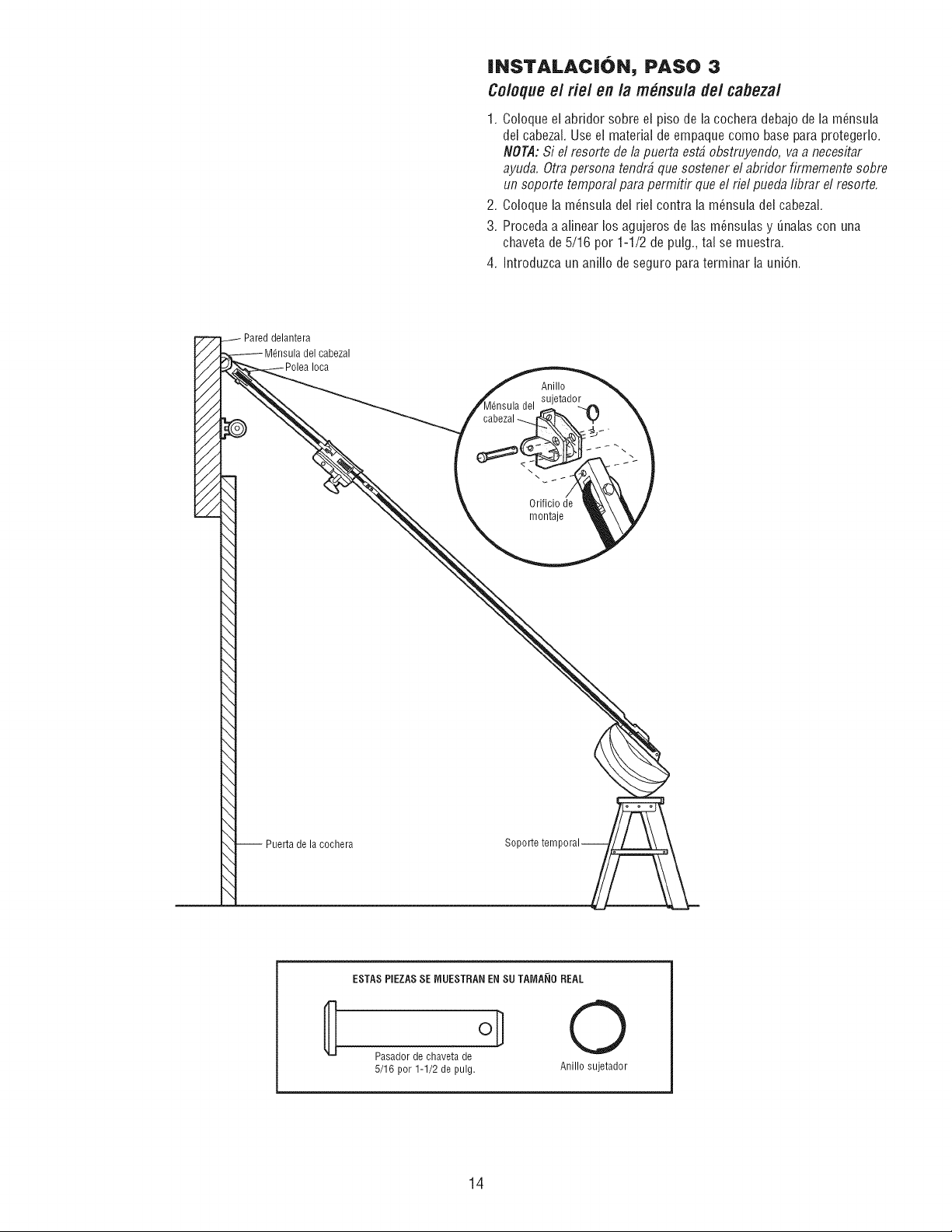
INSTALACION, PASO 3
Coloqueel fie/en la m_nsula de/cabezal
1. Coloque el abfidor sobre el piso de la cochera debajo de la m_nsula
del cabezal. Use el material de empaque como base para protegerlo.
NOTA: Si el resorte de la puerta est# obstruyendo, va a necesitar
ayuda. Otra persona tendr# que sostener el abridor firmemente sobre
un soporte temporal para permitir que el rid pueda librar el resorte.
2. Coloque la m_nsula del riel contra la m6nsula del cabezal.
3. Proceda a alinear los agujeros de las m_nsulas y _nalas con una
chaveta de5/16 por 1-1/2 de pulg., tal se muestra.
4. Introduzca un anillo de seguro para terminar la uni6n.
Anillo
,_tador
del
cabezal _
\
Orificiode
montaje
-- Puerta de la cochera
ESTASPIEZASSE IVlUESTRANEN SU TAIVIA_IOREAL
Pasador de chaveta de
5/16 por 1-1/2 de pulg.
0
Anillo sujetador
14
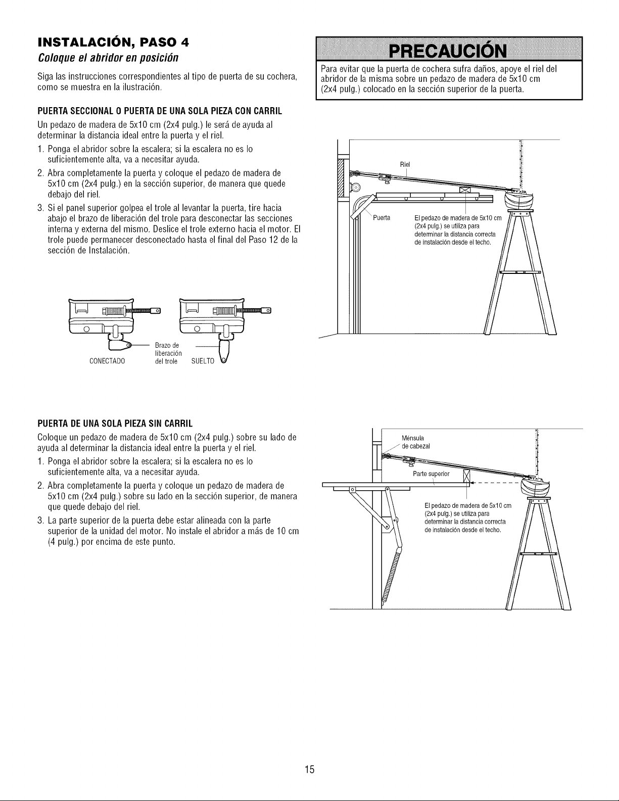
INSTALACION, PASO 4
Coloque el abridor en posici6n
Siga las instruccionescorrespondientes al tipo de puerta de su cochera,
como se muestra en la ilustraci6n.
PUERTASECCIONAL0 PUERTADE UNASOLAPIEZACON CARRIL
Un pedazode madera de 5x10 cm (2x4 pulg.) le ser_.de ayuda al
determinar la distancia ideal entre la puerta y el riel.
1. Ponga el abridor sobre la escalera; si la escalera no es Io
suficientemente alta, va a necesitar ayuda.
2. Abra completamente la puerta y coloque el pedazode madera de
5x10 cm (2x4 pulg.) en la secci6n superior, de manera que quede
debajo del riel.
3. Si el panel superior golpea el trole al levantar la puerta, tire hacia
abajo el brazo de liberaci6n del trole para desconectar las secciones
interna y externa del mismo. Deslice el trole externo hacia el motor. El
trole puede permanecer desconectado hasta el final del Paso 12 de la
secci6n de Instalaci6n.
Para evitar que la puerta de cochera sufra daSos, apoye el riel del
abridor de la misma sobre un pedazode madera de 5x10 cm
(2x4 pulg.) colocado en la secci6n superior de la puerta.
Riel
(2x4 pulg.)se utilizapara
Braze de --
eraci6
CONECTADO del trole SUELTO
PUERTADE UNASOLAPIEZASIN CARRIL
Coloque un pedazo de maderade 5x10 cm (2x4 pulg.) sobre su lado de
ayuda al determinar la distancia ideal entre la puerta y el riel.
1. Ponga el abridor sobre la escalera; si la escalera no es Io
suficientemente alta, va a necesitar ayuda.
2. Abra completamente la puerta y coloque un pedazode madera de
5x10 cm (2x4 pulg.) sobre su lado en la secci6n superior, de manera
que quede debajo del riel.
3. La parte superior de la puerta debe estar alineada con la parte
superior de la unidad del motor. No instale el abridor a m_.sde 10 cm
(4 pulg.) por encima de este punto.
I
Mensula
j de cabezal
Partesuperior
i
Elpedazo de madera de 5x10 cm
(2x4pulg.) se utilizapara
determinarla distanciacorrecta
de instalacbn desde eltecho.
15
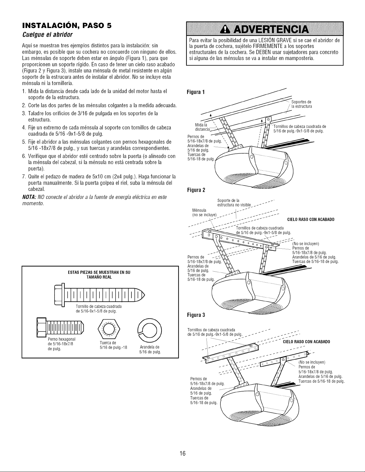
INSTALACION, PASO 5
Cuelgueel abridor
Aqui se muestran tres ejemplos distintos para la instalacibn; sin
embargo, es posible que su cochera no concuerde con ninguno de ellos.
Las m_nsulas de soporte deben estar en _.ngulo(Figura 1), para que
proporcionen un soporte rigido. En caso de tener un cielo raso acabado
(Figura 2 y Figura 3), instale una m_nsula de metal resistente en alg_n
soporte de la estrucura antes de instalar el abridor. No se incluye esta
m_nsula ni latornilleria.
1. Mida la distancia desde cada lado de la unidad del motor hasta el
soporte de la estructura.
2. Corte las dos partes de las m_nsulas colgantes a la medida adecuada.
3. Taladre los orificios de 3/16 de pulgada en los soportes de la
estructura.
4. Fije un extremo de cada m_nsula al soporte con tornillos de cabeza
cuadrada de 5/16 -9xl-5/8 de pulg.
5. Fije el abridor alas m_nsulas colgantes con pernos hexagonales de
5/16 -18x7/8 de pulg., y sus tuercas y arandelas correspondientes.
6. Verifique que el abridor est_ centrado sobre la puerta (o alineado con
la m_nsula del cabezal, si la m_nsula no est,. centradasobre la
puerta).
7. Quite el pedazode madera de 5x10 cm (2x4 pulg.). Hagafuncionar la
puerta manualmente. Si la puerta golpea el riel, suba la m_nsula del
cabezal.
NOTA:NO conecteel abridor a la fuente de energfa el#ctrica en este
momento.
ESTASPIEZASSE MUESTRAN ENSU
TAMA_IOREAL
'To'rn,,,'odJcaleza'culdra'd '''>
de 5/16-9xl-5/8 de pulg.
_ IPelrnlol I I I I I I_
hexagonal
de 5/16-18x7/8 Tuerca de
de pulg. 5/16 de pulg.-18
Arandela de
5/16 de pulg.
Para evitar la posibilidad de una LESIONGRAVEsi se cae el abridor de
la puerta de cochera, suj_telo FIRMEMENTEa los soportes
estructurales de la cochera. Se DEBENusar sujetadores para concreto
si alguna de las m_nsulas se va a instalar en mamposteria.
Figura1
)ortes de
estructura
Mida la ',
Pernos de ,
5/16-18x7/8 de pulg. ,,
Arandelas de
5/16 de pulg.
Tuercas de
5/16-18 de pulg
\ Tornillos de cabeza cuadrada de
5/16 de pulg.-9xl-5/8 de pulg.
Figura2
Pernos de _c:
5/16-18x7/8 de pulg.
Arandelas de
5/16 de pulg.
Tuercas de
5/16-18 de pulg.
(No se incluyen)
Pernos de
5/16-18x7/8 de pulg.
Arandelas de 5/16 de pulg.
Tuercas de 5/16-18 de pulg.
Figura3
Tornillos de cabeza cuadrada
de 5/16 de _ _ _ _ _ _ _ _ _ ;_'---
pulg.-9xl-5/8 de pulg.
Pernos de
5/16-18x7/8 de pulg.
Arandelas de
5/16 de pulg.
Tuercas de
5/16-18 de pulg.
(No se incluyen)
Pernos de
5/16-18x7/8 de pulg.
Arandelas de 5/16 de pulg.
Tuercas de 5/16-18 de pulg.
16
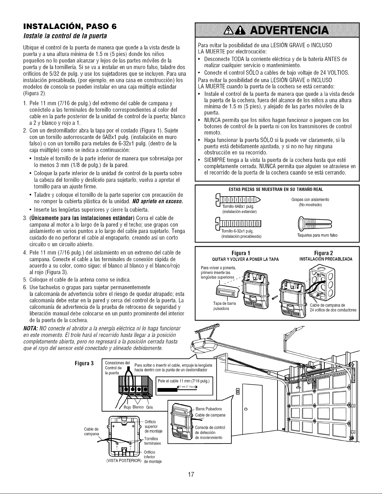
INSTALACION, PASO 6
Instalela controldela puerta
Ubique el control de la puerta de manera que quede a la vista desde la
puerta y a una altura minima de 1.5 m (5 pies) donde los niSos
pequeSos no Io puedan alcanzary lejos de las partes m6viles de la
puerta y de la tornilleria. Si se va a instalar en un muro falso, taladre dos
orificios de 5/32 de pulg. y use los sujetadores que se incluyen. Para una
instalaci6n precableada,(por ejemplo, en una casa en construcci6n) los
modelos de consola se pueden instalar en una caja mOItipleest_.ndar
(Figura 2).
1. Pele 11 mm (7/16 de pulg.) del extremo del cable de campana y
con@telo a las terminales de tornillo correspondientes al color del
cable en la parte posterior de la unidad de control de la puerta; blanco
a 2 y blanco y rojo a 1.
2. Con un destornillador abra latapa por el costado (Figura 1). Sujete
con un tornillo autorroscante de 6ABxl pulg. (instalaci6n en muro
falso) o con un tornillo para metales de 6-32xl pulg. (dentro de la
caja mOItiple)como se indica a continuaci6n:
• Instale el tornillo de la parte inferior de manera que sobresalga por
Io menos 3 mm (1/8 de pulg.) de la pared.
• Coloque la parte inferior de la unidad de control de la puerta sobre
la cabezadel tornillo y deslicelo para sujetarlo, vuelva a apretar el
tornillo para un ajuste firme.
• Taladre y coloque el tornillo de la parte superior con precauci6n de
no romper la cubierta pl_.sticade la unidad. NO apriete en exceso.
• Inserte las lengOetassuperiores y cierre la cubierta.
3. (Onicamente para las instalaciones est_ndar) Corra el cable de
campana al motor a Io largo de la pared y el techo; use grapas con
aislamiento en varios puntos a Io largo del cable para sujetarlo. Tenga
cuidado de no perforar el cable al engraparlo, creando asi un corto
circuito o un circuito abierto.
4. Pele 11 mm (7/16 pulg.) del aislamiento en un extremo del cable de
campana. Conecte el cable alas terminales de conexi6n r_.pidade
acuerdo a su color, como sigue: el blanco al blanco y el blanco/rojo
al rojo (Figura 3).
5. Coloque el cable de la antena como se indica.
6. Usetachuelas o grapas para sujetar permanentemente
la calcomania de advertencia sobre el riesgo de quedar atrapado; esta
calcomania debe estar en la pared y cerca del control de la puerta. La
calcomania de advertencia de la prueba de retroceso de seguridad y
liberaci6n manual debe colocarse en un punto prominente del interior
de la puerta de la cochera.
NOTA: NO conectee/abridor a/a energfa e/#ctrica ni /o haga funcionar
en este momento. El tro/e har# e/recorrido hasta //egar a/a posiciSn
comp/etamente abierta, pero no regresar# a/a posiciSn cerrada hasta
que e/rayo de/sensor est# conectadoy a/ineado debidamente.
Para evitar la posibilidad de una LESIONGRAVEo INCLUSO
LA MUERTEpor electrocuci6n:
• DesconecteTODA la corriente el@trica y de la bateria ANTESde
realizar cualquier servicio o mantenimiento.
• Conecte el control SOLOa cables de bajo voltaje de 24 VOLTIOS.
Para evitar la posibilidad de una LESIONGRAVEo INCLUSO
LA MUERTEcuando la puerta de la cochera se est,. cerrando:
• Instale el control de la puerta de manera que quedea la vista desde
la puerta de la cochera, fuera del alcance de los niSos a una altura
minima de 1.5 m (5 pies), y alejado de las partes m6viles de la
puerta.
• NUNCApermita que los niSos haganfuncionar o jueguen con los
botones de control de la puerta ni con los transmisores de control
remoto.
• Hagafuncionar la puerta SOLOsi la puede ver claramente, si la
puerta est,. debidamente ajustada, y si no no hay ninguna
obstrucci6n en su recorrido.
• SIEMPREtenga a la vista la puerta de la cochera hasta que est_
completamente cerrada. NUNCApermita que alguien se atraviese en
el recorrido de la puerta de la cochera cuando se est,. cerrando.
ESTAS PIEZAS SE MUESTRAN ENSU TAMANO REAL
_ ilililililililil_
Tornillo6ABxl pulg.
(instalaci6nestandar)
(instalacidnprecableada)
Grapas con aislamiento
(No mostrado)
Taquetesparamurofalso
Figura1
QUITARY VOLVER A PONERLA TAPA
Paravolver a ponerla,
primeroinsertelas
lengQetassuperiores
Tapa de barra
pulsadora
Figura2
INSTALACIONPRECABLEADA
Cable de campanade
24 voltios dedos conductores
Figura3
Cable de
campana
Parasoltar o insertirel cable, empuje la lengeeta
haciadentrocon la punta de un destornillador
Pele el cable 11mm (7/16 pulg.)
,_11 mm (7, 6pug_
Roio Gr, [ BarraPu,sadora
*1 I superior _ Consola de control
I _ de montaje L_7_t'_!ll de detecci6n
_Tornillos _ de movienmiento
_i terminales
Orificio
inferior
VISTA POSTERIOR de montaje
O
17
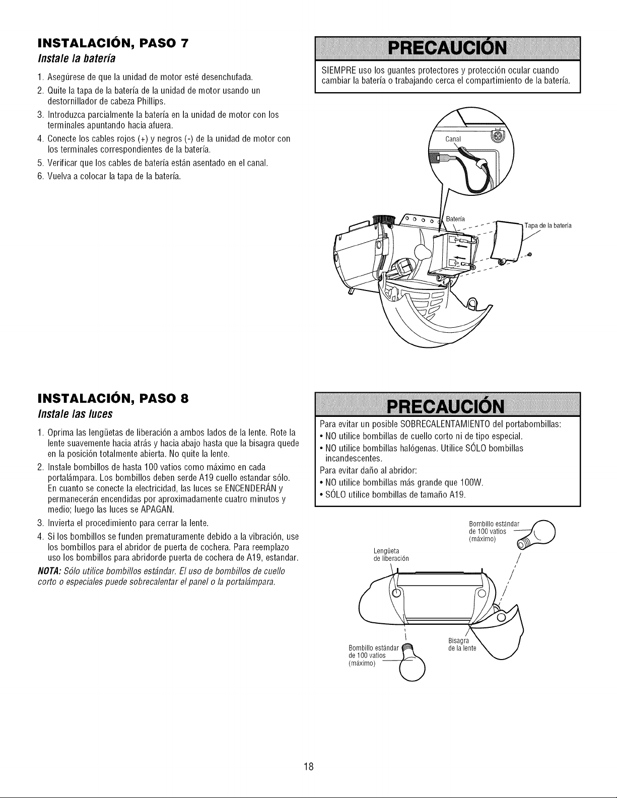
INSTALACION, PASO 7
Insta/e /a bateria
1. Aseg_resede que la unidad de motor est_ desenchufada.
2. Quite la tapa de la bateria de la unidad de motor usando un
destornillador de cabeza Phillips.
3. Introduzca parcialmente la bateria en la unidad de motor con los
terminales apuntando haciaafuera.
4. Conecte los cables rojos (+) y negros (-) de la unidad de motor con
los terminales correspondientes de la bateria.
5. Verificar que los cables de bateria est_.nasentado en el canal.
6. Vuelva a colocar la tapa de la bateria.
SIEMPRE uso los guantes protectores y protecci6n ocular cuando
cambiar la bateria o trabajando cerca el compartimiento de la bateria.
de la baterfa
INSTALACION, PASO 8
Instale /as luces
1. Oprima las lengiJetasde liberaci6n a ambos lados de la lente. Rote la
lente suavemente hacia atr_.sy hacia abajo hasta que la bisagra quede
en la posici6n totalmente abierta. No quite la lente.
2. Instale bombillos de hasta 100 vatios como m_.ximo en cada
portal_mpara. Los bombillos deben serde A19 cuello estandars61o.
En cuanto se conecte la electricidad, las luces se ENOENDERANy
permanecer_.nencendidas por aproximadamente cuatro minutos y
medio; luego las luces se APAGAN.
3. Invierta el procedimiento para cerrar la lente.
4. Si los bombillos se funden prematuramente debido a la vibraci6n, use
los bombillos para el abridor de puerta de cochera. Para reemplazo
uso los bombillos para abridorde puerta de cochera de A19, estandar.
NOTA: S51outilice bombiflos est#ndar. El uso de bombillos de cuello
corto o especiales puede sobrecalentar el panel o la portal#mpara.
Para evitar un posible SOBRECALENTAMIENTOdel portabombillas:
• NO utilice bombillas de cuello corto ni de tipo especial.
• NO utilice bombillas hal6genas.Utilice SOLO bombillas
incandescentes.
Para evitar daSo al abridor:
• NO utilice bombillas m_.sgrande que 100W.
• SOLOutilice bombillas de tama_o A19.
Leng0eta
de liberaci0n
Bombillo estandar
de 100 vatios ----_t )
(maximo)
/
/
/
Bombillo estandarb
de 100 vatios
(maximo) --
Bisagra
de lalente
18
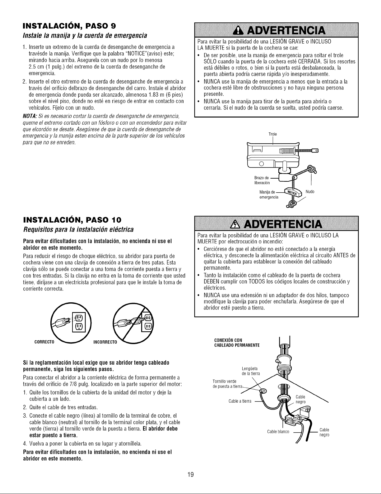
INSTALACION, PASO 9
Instale la manija y la cuerdade emergencia
1. Inserte un extremo de la cuerda de desenganche de emergencia a
trav_sde la manija. Verifique que la palabra "NOTICE"(aviso) este;
mirando hacia arriba. Asegurela con un nudo por Io menosa
2.5 cm (1 pulg.) del extremo de la cuerda de desenganchede
emergencia.
2. Inserte el otro extremo de la cuerda de desenganchede emergencia a
trav_s del orificio delbrazo de desenganche del carro. Instale el abridor
de emergencia donde pueda ser alcanzado, almenosa 1.83 m (6 pies)
sobre el nivel piso, donde no est_ en riesgo de entrar en contacto con
vehiculos. Fijelo con un nudo.
NOTA:Si es necesario cortar la cuerda de desenganchede emergencia,
queme el extremo cortado con un f6sforo o con un encendedorpara evitar
que elcord6n se desate.AsegEiresede que la cuerda de desenganchede
emergencia y la manija esten encima de laparte superior de los vehfculos
para que no se enreden.
INSTALACION, PASO 10
Requisitosparala instalaci6nel ctrica
Para evitar dificultades conla instalaci6n, no encienda ni use el
abridor en este momento.
Para reducir el riesgo de choque el_ctrico, su abridor para puerta de
cochera viene con una clavija de conexi6n a tierra detres patas. Esta
clavija s61ose puedeconectar a una toma de corriente puesta a tierra y
con tres entradas. Si la clavija no entra en la toma de corriente que usted
tiene, dirijase a un electricista profesional para que le instale la toma de
corriente correcta.
CORRECT_
INCORRECT0
Para evitar la posibilidad de una LESIONGRAVEo INCLUSO
LA MUERTEsi la puerta de la cochera se cae:
• De ser posible, use la manija de emergencia para soltar el trole
SOLOcuando la puerta de la cochera est_ CERRADA.Si los resortes
est,. d_biles o rotos, o bien si la puerta est,. desbalanceada,la
puerta abierta podria caerse r_.piday/o inesperadamente.
• NUNCAuse la manija de emergencia a menos que la entrada a la
cochera est_ libre de obstrucciones y no haya ninguna persona
presente.
• NUNCAuse la manija para tirar de la puerta para abrirla o
cerrarla. Si el nudo de la cuerda se suelta, usted podria caerse.
Trole
I
Manijade -_ _ Nudo
emergencia
Para evitar la posibilidad de una LESIONGRAVEo INCLUSOLA
MUERTEpor electrocuci6n o incendio:
• Cerci6rese de que el abridor no est_ conectado a la energia
el6ctrica, y desconecte la alimentaci6n el_ctrica al circuito ANTESde
quitar la cubierta para establecer la conexi6n del cableado
permanente.
• Tanto la instalacidn como el cableado de la puerta de cochera
DEBENcumplir con TODOSlos c6digos locales de construcci6n y
el_ctricos.
• NUNCAuse una extensi6n ni un adaptador de dos hilos, tampoco
modifique la clavija para poder enchufarla. Aseg0rese de que el
abridor est6 puesto a tierra.
CONEXIONCON
CABLEAD0PERMANENTE
Si la reglamentaci6n local exige que su abridor tenga cableado
permanente, siga los siguientespasos.
Para conectar el abridor a la corriente el_ctrica de forma permanente a
trav6s del orificio de 7/8 pulg. Iocalizado en la parte superior del motor:
1. Quite los tornillos de la cubierta de la unidad del motor y deje la
cubierta a un lado.
2. Quite el cable de tres entradas.
3. Conecte el cable negro (linea) al tornillo de laterminal de cobre, el
cable blanco (neutral) al tornillo de la terminal color plata, y el cable
verde (tierra) al tornillo verde de la puesta a tierra. El abridor debe
estar puesto a tierra.
4. Vuelva a poner la cubierta en su lugar y atornillela.
Para evitar dificultades conla instalaci6n, no encienda ni use el
abridor en este momento.
LengOeta
de la tierra
Tornillo verde
de puesta atierra_
Cable a tierra
negro
Cable blanco Cable
negro
19
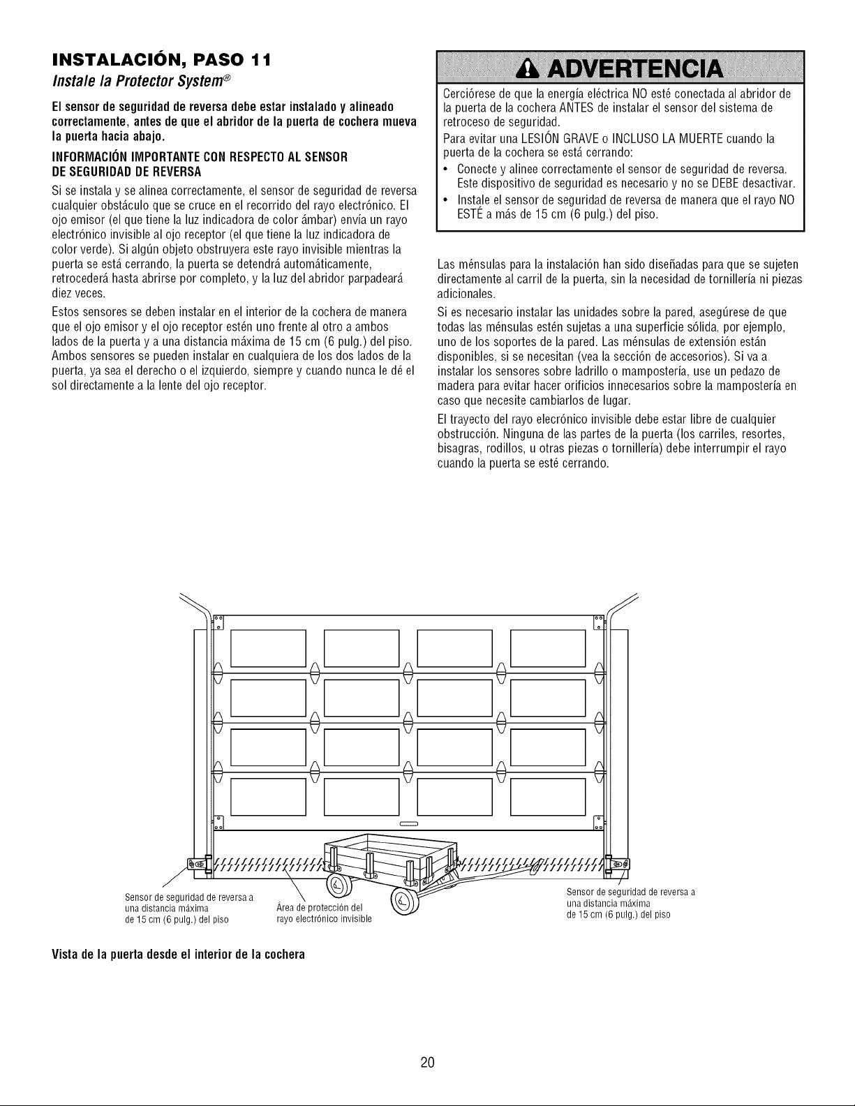
INSTALACION, PASO 11
Insta/e /a ProtectorSystem®
El sensorde seguridadde reversa debe estar instaladoy alineado
correctamente, antes de que el abridor de la puerta de cochera mueva
la puerta hacia abajo.
INFORMACIONIMPORTANTECON RESPECT0AL SENSOR
DESEGURIDADDE REVERSA
Si se instala y se alinea correctamente, el sensor de seguridad de reversa
cualquier obst_.culoque se cruce en el recorrido del rayo electr6nico. El
ojo emisor (el que tiene la luz indicadora de color _.mbar)envia un rayo
electr6nico invisible al ojo receptor (el que tiene la luz indicadora de
color verde). Si alg_n objeto obstruyera este rayo invisible mientras la
puerta se est,. cerrando, la puerta se detendr_,autom_.ticamente,
retroceder_,hasta abrirse por completo, y la luz del abridor parpadear_.
diez veces.
Estos sensores se deben instalar en el interior de la cochera de manera
que el ojo emisor y el ojo receptor est_n uno frente al otro a ambos
lados de la puerta y a una distancia m_.ximade 15 cm (6 pulg.) del piso.
Ambos sensores se pueden instalar en cualquiera de los dos lados de la
puerta, ya sea el derecho o el izquierdo, siempre y cuando nunca le d_ el
sol directamente a la lente del ojo receptor.
Cerci6rese de que la energia el_ctrica NOest_ conectadaal abridor de
la puerta de la cochera ANTESde instalar el sensor del sistema de
retroceso de seguridad.
Para evitar una LESIONGRAVEo INCLUSOLA MUERTEcuando la
puerta de la cochera se est,. cerrando:
• Conecte y alinee correctamente el sensor de seguridad de reversa.
Este dispositivo de seguridad es necesario y no se DEBEdesactivar.
• Instale el sensor de seguridad de reversa de manera que el rayo NO
ESTI_a m_.sde 15 cm (6 pulg.) del piso.
Las m_nsulas para la instalaci6n han sido diseSadas para que se sujeten
directamente al carril de la puerta, sin la necesidad de tornilleria ni piezas
adicionales.
Si es necesario instalar las unidades sobre la pared, aseg_rese de que
todas las m_nsulas est_n sujetas a una superficie s61ida,por ejemplo,
uno de los soportes de la pared. Las m_nsulas de extensi6n est_.n
disponibles, si se necesitan (vea la secci6n de accesorios). Siva a
instalar los sensores sobre ladrillo o mamposteria, use un pedazode
madera para evitar hacer orificios innecesarios sobre la mamposteria en
caso que necesite cambiarlos de lugar.
El trayecto del rayo elecr6nico invisible debe estar libre de cualquier
obstrucci6n. Ninguna de las partes de la puerta (los carriles, resortes,
bisagras, rodillos, u otras piezas o tornilleria) debe interrumpir el rayo
cuando la puerta se est_ cerrando.
Vistade la puertadesdeel interiorde la cochera
20
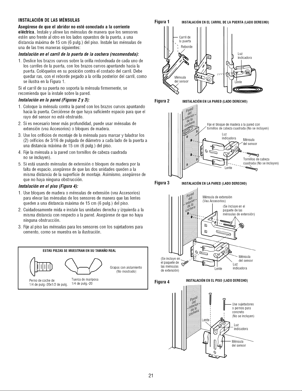
INSTALACIONDE LASMI_NSULAS
Aseg_rese de que el abridor no est_ conectadoa la corriente
el_ctrica. Instale y alinee las m_nsulas de manera que los sensores
est_n uno frente al otro en los lados opuestos de la puerta, a una
distancia m_.xima de 15 cm (6 pulg.) del piso. Instale las m_nsulas de
una de lastres maneras siguientes:
Instalaci6n en el carril de la puerta de la cochera (recomendada):
1. Deslice los brazos curvos sobre la orilla redondeadade cada uno de
los carriles de la puerta, con los brazoscurvos apuntando hacia la
puerta. Col6quelos en su posici6n contra el costado del carril. Debe
quedar ras, con el reborde pegado a la orilla posterior del carril, como
se ilustra en la Figura 1.
Si el carril de su puerta no soporta la m_nsula firmemente, se
recomienda que la instale sobre la pared.
Instalaci6n en la pared (Figuras 2 y 3):
1. Coloque la m_nsula contra la pared con los brazos curvos apuntando
hacia la puerta. Cerci6rese de que haya suficiente espacio para que el
rayo del sensor no est_ obstruido.
2. Si es necesario tener m_.sprofundidad, puede usar m_nsulas de
extensi6n (yea Accesorios) o bloques de madera.
3. Use los orificios de montaje de la m_nsula para marcar y taladrar los
(2) orificios de 3/16 de pulgada de di_metro a cada lado de la puerta a
una distancia m_.ximade 15 cm (6 pulg.) del piso.
4. Fije la m_nsula a la pared con tornillos de cabezacuadrada
no se incluyen).
5. Si est,. usando m_nsulas de extensi6n o bloques de madera por la
falta de espacio, aseg_rese deque las dos unidades queden a la
misma distancia de la superficie de montaje. Asimismo, aseg_rese de
que no haya ninguna obstrucci6n.
Instalaci6n en el piso (Figura 4):
1. Use bloques de madera o m_nsulas de extensi6n (yea Accesorios)
para elevar las m_nsulas de los sensores de manera que las lentes
queden a una distancia m_ima de 15 cm (6 pulg.) del piso.
2. Cuidadosamente mida e instale las unidades derecha y izquierdaa la
misma distancia con respecto a la pared. Aseg_rese de que no haya
ninguna obstrucci6n.
3. Fije al piso las m_nsulas para los sensores con los sujetadores para
cemento, como se muestra en la ilustraci6n.
ESTASPIEZASSE MUESTRAN EN SUTAMA_IO REAL
Perno de coche de Tuerca de mariposa
1/4 de pulg.-2Oxl/2 de pulg. 1/4 de pulg.-20
Grapas con aislamiento
(1/o mostrado)
Figura1 INSTALACIONEN ELCARRIL DE LA PUERTA(LADO DERECHO)
Carril de
'?eUCe
7---- -
Figura2 INSTALACIONEN LA PARED (LADO DERECHO)
Fijeel bloque de madera a la pared con
J tornillos de cabezacuadrada (No se incluyen)
Luz
indicadora Mdnsula
sensor
_Tornillos decabeza
___..t 1...... cuadrada(Nose incluyen)
_ Lente .... _
Figura3 INSTALACIONEN LA PARED(LADO DERECHO)
Mdnsula de extensi@
(VeaAccesorios)
-_ (pmSaiii!_!i !n _ien s,On)
(Seincleyeen .. M_nsula
_paqueZ:l_ "_,'_..i_l _zuzd.........
de extensi6n) Lente indicadora
Figura4
INSTALACIONENEL PISO (LADO DERECHO)
i F Use sujetadores
, o pernos para
, concreto
(No se incluyen)
Luz
indicadora
del sensor
21
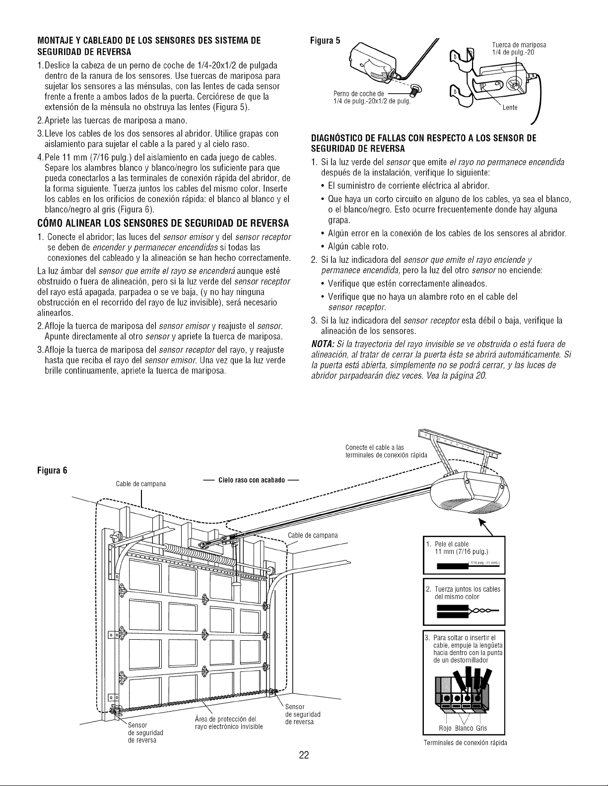
MONTAJEY CABLEADODE LOSSENSORESDESSISTEMADE
SEGURIDADDEREVERSA
1.Deslice la cabeza de un perno de coche de 1/4-20xl/2 de pulgada
dentro de la ranura de los sensores. Use tuercas de mariposa para
sujetar los sensores alas m_nsulas, con las lentes de cada sensor
frente a frente a ambos lados de la puerta. Cerci6rese de que la
extensi6n de la m_nsula no obstruya las lentes (Figura 5).
2.Apriete las tuercas de mariposa a mano.
3.Lleve los cables de los dos sensores al abridor. Utilice grapas con
aislamiento para sujetar el cable a la pared y al cielo raso.
4.Pele 11 mm (7/16 pulg.) del aislamiento en cada juego de cables.
Separe los alambres blanco y blanco/negro los suficiente para que
pueda conectarlos alas terminales de conexi6n r_.pidadel abridor, de
la forma siguiente. Tuerzajuntos los cables del mismo color. Inserte
los cables en los orificios de conexi6n r_.pida:el blanco al blanco y el
blanco/negro al gris (Figura 6).
COMO ALINEAR LOS SENSORES DE SEGURIDAD DE REVERSA
1. Conecteel abridor; las luces del sensor emisor y del sensor receptor
se deben de encendery permanecer encendidas si todas las
conexiones del cableado y la alineaci6n se han hecho correctamente.
La luz _.mbardel sensor que emite el rayo se encender#aunque est_
obstruido o fuera dealineaci6n, pero si la luz verde del sensor receptor
del rayo est,. apagada, parpadea o se ve baja, (y no hay ninguna
obstrucci6n en el recorrido del rayo de luz invisible), ser_.necesario
alinearlos.
2.Afloje latuerca de mariposa del sensor emisor y reajuste el sensor.
Apunte directamente al otro sensory apriete la tuerca de mariposa.
3.Afloje latuerca de mariposa del sensor receptor del rayo, y reajuste
hasta que reciba el rayo del sensor emisor. Una vez que la luz verde
brille continuamente, apriete latuerca de mariposa.
Figura5
Tuerca de mariposa
Perno de coche de ---_ -_
1/4 de pulg.-2Oxl/2 de pulg.
DIAGNOSTICODE FALLASCON RESPECTOA LOSSENSORDE
SEGURIDADDE REVERSA
1. Si la luz verde del sensorque emite el rayo no permanece encendida
despu6s de la instalaci6n, verifique Io siguiente:
• El suministro de corriente el_ctrica al abridor.
• Que haya un corto circuito en alguno de los cables, ya sea el blanco,
o el blanco/negro. Esto ocurre frecuentemente donde hay alguna
grapa.
• AIg_n error en la conexi6n de los cables de los sensores al abridor.
• AIg_n cable roto.
2. Si la luz indicadora del sensor que emite el rayo enciendey
pennanece encendida, pero la luz del otro sensor no enciende:
• Verifique que est6n correctamente alineados.
• Verifique que no haya un alambre roto en el cable del
sensor receptor.
3. Si la luz indicadora del sensor receptor estad6bil o baja, verifique la
alineaci6n de los sensores.
NOTA: Si la trayectoria del rayo invisible seve obstruida o est# fuera de
alineaciSn,al tratar de cerrar la puerta #sta se abrir# autom#ticamente. Si
la puerta est#abierta, simplemente no se podr# cerrar, y las luces de
abridor parpadear#n diez veces. Veala p#gina 20.
Figura6
Cablede campana
'Sensor
de seguridad
de reversa
Conecteel cable alas
terminales de conexiOn r_pida
-- Cielo raso conacabado -- .......... " ....
p
Cable de campana
\
1. Pele el cable
11mm(7/16pulg.)
I 7_16 pulg (11 ram) I
2. Tuerza juntos los cables
del mismo color
Area de protecciOn del
rayo electrOnico invisible
Sensor
de seguridad
de reversa
22
3. Para soltar o insertir el
cable, empuje la leng_Jeta
hacia dentro con la punta
de un destornillador
Rojo Blanco Gris
Terminales de conexi6n r_pida
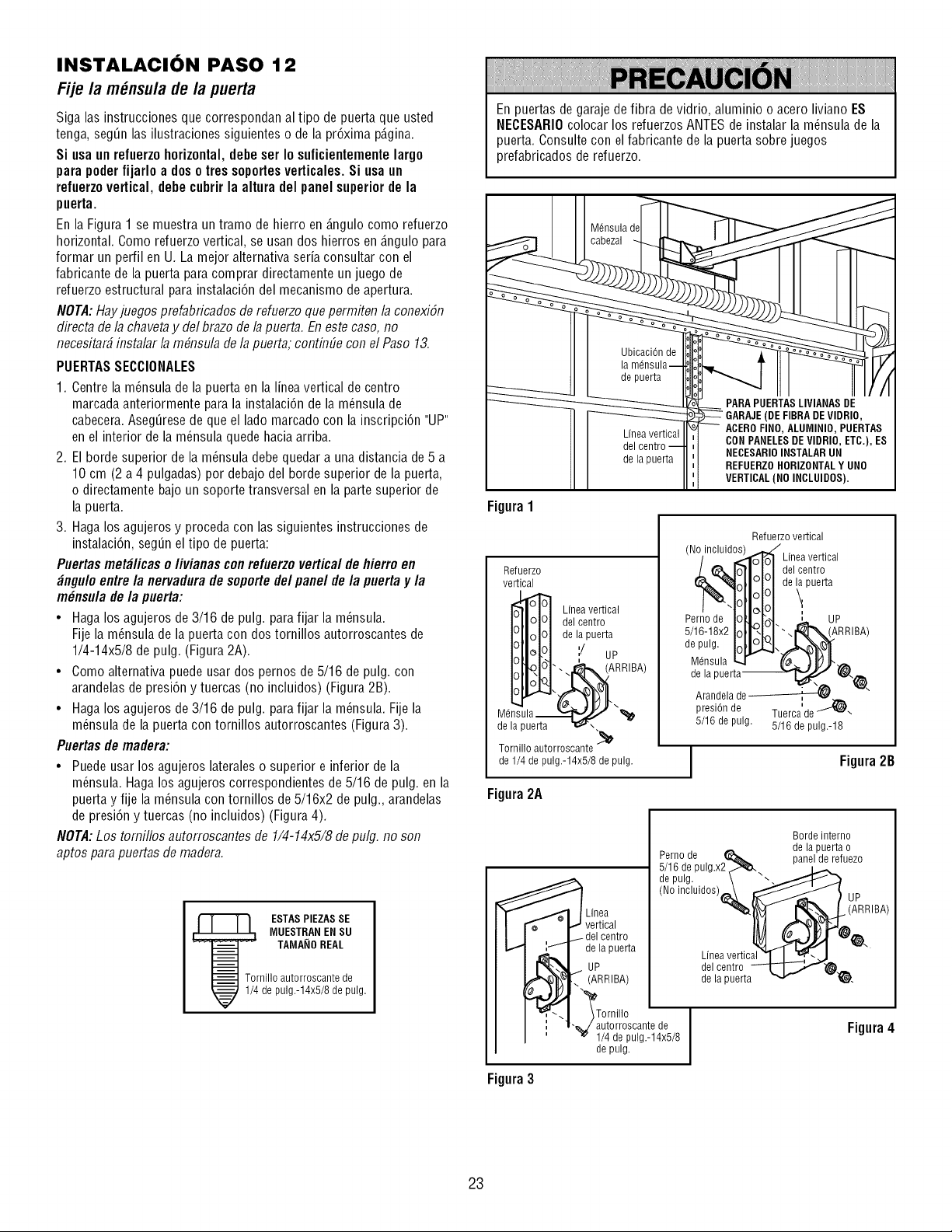
INSTALACION PASO 12
Fije la m_nsula de/a puerta
Siga las instrucciones que correspondan al tipo de puerta que usted
tenga, segQnlas ilustraciones siguientes o de la pr6xima p_.gina.
Si usa un refuerzohorizontal, debe ser Io suficientemente largo
para poderfijarlo a doso tres soportesverticales. Si usa un
refuerzovertical, debe cubrir la altura del panel superiorde la
puerta.
En la Figura 1 se muestra un tramo de hierro en _.ngulocomo refuerzo
horizontal. Como refuerzo vertical, se usan dos hierros en _.ngulopara
formar un perfil en U. La mejor alternativa seria consultar con el
fabricante de la puerta para comprar directamente un juego de
refuerzo estructural para instalaci6n del mecanismo de apertura.
NOTA:Hayjuegos prefabricados de refuerzo quepermiten la conexiSn
directa de la chaveta y del brazo de la puerta. En este caso, no
necesitar# instalar la m#nsula de la puerta; continfie con el Paso 13.
PUERTASSECCIONALES
1. Centre la m_nsula de la puerta en la linea vertical de centro
marcada anteriormente para la instalaci6n de la m_nsula de
cabecera.Aseg_rese de que el lado marcado con la inscripci6n "UP"
en el interior de la m_nsula quede hacia arriba.
2. El borde superior de la m_nsula debe quedar a una distancia de 5 a
10 cm (2 a 4 pulgadas) por debajo del borde superior de la puerta,
o directamente bajo un soporte transversal en la parte superior de
la puerta.
3. Haga los agujeros y proceda con las siguientes instrucciones de
instalaci6n, seg_n el tipo de puerta:
Puertas met_licas o/ivianas con refuerzo vertical de flierro en
_ngu/o entre/a nervadurade soporte de/panel de/a puerta y/a
m_nsu/a de/a puerta:
• Haga los agujeros de 3/16 de pulg. para fijar la m_nsula.
Fije la m6nsula de la puerta con dos tornillos autorroscantes de
1/4-14x5/8 de pulg. (Figura 2A).
• Como alternativa puede usar dos pernos de 5/16 de pulg. con
arandelas de presi6n y tuercas (no incluidos) (Figura 2B).
• Haga los agujeros de 3/16 de pulg. para fijar la m6nsula. Fije la
m_nsula de la puerta con tornillos autorroscantes (Figura3).
Puertas de madera:
• Puede usar los agujeros lateraleso superior e inferior de la
m6nsula. Haga los agujeros correspondientes de 5/16 de pulg. en la
puerta y fije la m_nsula con tornillos de 5/16x2 de pulg., arandelas
de presi6n y tuercas (no incluidos) (Figura 4).
NOTA:Los tomillos autorroscantes de 1/4-14x5/8 de pulg. no son
aptos para puertas de madera.
--J TAMA_IOREAL
Tornillo autorroscante de
1/4 de pulg.-14x5/8 de pulg.
En puertas de garaje de fibra de vidrio, aluminio o acero liviano ES
NECESARIOcolocar los refuerzos ANTESde instalar la m_nsula de la
puerta. Consulte con el fabricante de la puerta sobre juegos
prefabricados de refuerzo.
Figura1
Refuerzo
vertical
_----'1olOI Lineavertical
I_11olOI delcentro
FIIr4oI de lapuerta
ii°.J
dMed_s_'Lae_
Tornilloautorroscante
de 1/4 de pulg.-14x5/8 de pulg.
Figura2A
(
ACEROFINO, ALUMINIO, PUERTAS
CON PANELESDEVIDRIO, ETC.), ES
NECESARIOINSTALAR UN
REFUERZOHORIZONTALY UNO
VERTICAL(NO INCLUIDOS).
Refuerzo vertical
(No/incluid_ Linea vertical
1_5,.1_1.1_,1 del centro
%, ;tlililde ipaerta
Pernode IOlL,M. L up
5/16-18x2Iot KI".At'N/ARR'BA>
de pulg, p_.J.,./_.h_
Udnsula '-4 _'_-_ _[0jl"
de la puerta_ t_.
Arandela de_
i
presi6n de Tuerca'de J_\
5/16 de pulg. 5/16 de pulg.-18
Figura2B
Linea
vertical
centro
de la puerta
UP
(ARRIBA)
Borde interno
, _ de la puerta o
e+rno,ae , rdi_,,, panel de refuezo
/] b ae pu_g.xz _
de pulg. \ _'-.___
Linea vertica_ _
del centro _..,,,,_._
de la puerta _ "_"_.
Figura3
autorroscante de
1/4 de pulg.-14x5/8
de pulg.
J
Figura4
23
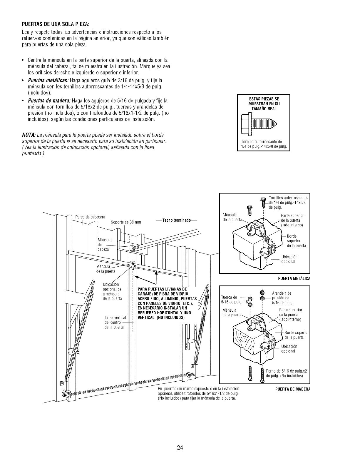
PUERTASDEUNASOLAPIEZA:
Lea y respetetodas las advertencias e instrucciones respecto a los
refuerzos contenidas en la p_.ginaanterior, ya que son v_.lidastambi_n
para puertas de una sola pieza.
• Centre la m_nsula en la parte superior de la puerta, alineadacon la
m_nsula del cabezal, tal se muestra en la ilustraci6n. Marque ya sea
los orificios derecho e izquierdo o superior e inferior.
• Puertas met_licas: Hagaagujeros guia de 3/16 de pulg. y fije la
m_nsula con los tornillos autorroscantes de 1/4-14x5/8 de pulg.
(incluidos).
• Puertas de madera: Haga los agujeros de 5/16 de pulgada y fije la
m_nsula con tornillos de 5/16x2 de pulg., tuercas y arandelasde
presi6n (no incluidos), o con tirafondos de 5/16x1-1/2 de pulg. (no
incluidos), seg_n las condiciones particulares de instalaci6n.
NOTA:La m#nsu/a para /a puerta puede ser flTsta/adasobre el borde
superior de/a puerta si es necesario para su insta/aciSn en particular.
(Vea/a i/ustraciSn de co/ocaciSnopciona/, sefia/ada con/a/flTea
punteada.)
ESTASPIEZAS SE
MUESTRAN EN SU
TA[VlA_IOREAL
Tornillo autorroscante de
1/4 de pulg.-14x5/8 de pulg.
Pared de cabecera
de la puerta
Soportede38 mm
opcional del
a mdnsula
de la puerta
Linea vertical
del centro
de la puerta
--Techo terminado--
PARA PUERTASLIVIANAS DE
GARAJE(DE FIBRA DEVIDRIO,
ACEROFINO, ALUMINIO, PUERTAS
CONPANELESDE VIDRIO, ETC.),
ES NECESARIOINSTALARUN
REFUERZOHORIZONTALY UNO
VERTICAL.(NO INCLUIDOS
M6nsula
de la
En puertas sin marco expuesto o en la instalacion
opcional, utilice tirafondos de 5/16x1-1/2 de pulg.
(No incluidos) para fijar la m6nsula de la puerta.
_1, Tornillos autorroscantes
t_--de 1/4 de pulg.-14x5/8
_de pulg.
+
, Parte superior
de la puerta
(lado interno)
Borde
superior
dela puerta
UbicaciOn
opcional
PUERTAIVIETALICA
Tuerca de
5/16 de pulg.-]8+
M6nsula
de la
_ randela de
presiOn de
5/16 de pulg.
Parte superior
de la puerta
(lado interno)
Borde superior
de la puerta
Ubicaci6n
opcional
_--Perno de 5/16 de pulg.x2
de pulg. (No incluidos)
PUERTADEIVIADERA
24
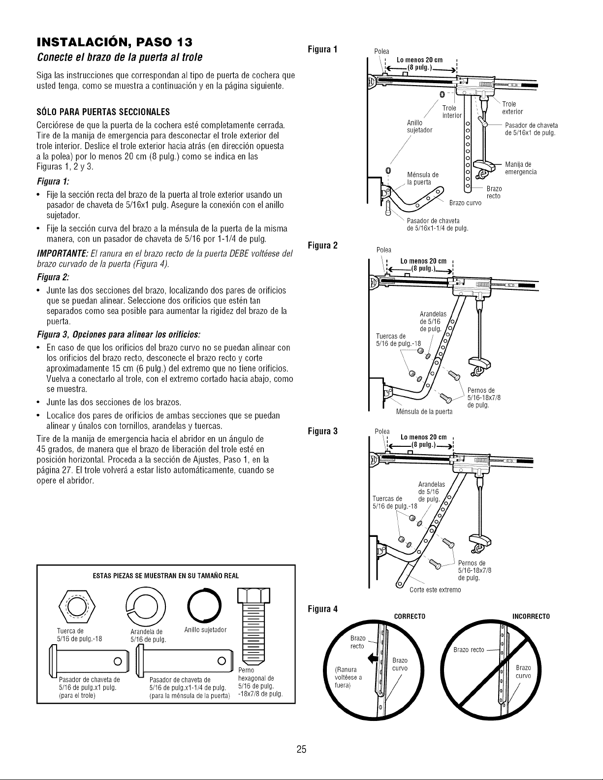
INSTALACION, PASO 13
Conecte el brazo de la puerta al trole
8ioa las instruccionesque correspondan al tipo de puerta de cochera que
usted tenoa, como se muestra a continuaci6n yen la p_.oinasiouiente.
Figura1
SOLOPARA PUERTASSECCIONALES
Cerci6rese de que la puerta de la cochera est_ completamente cerrada.
Tire de la manija de emergencia para desconectar el trole exterior del
trole interior. Deslice el trole exterior hacia atr_.s(en direcci6n opuesta
a la polea) por Io menos 20 cm (8 pulg.) como se indica en las
Figuras 1,2 y 3.
Figura 1:
• Fije la secci6n recta del brazo de la puertaal trole exterior usando un
pasador de chavetade 5/16xl pulg. Asegure la conexi6n con el anillo
sujetador.
• Fije la secci6n curva del brazoa la m_nsula de la puerta de la misma
manera, con un pasador de chaveta de 5/16 por 1-1/4 de pulg.
Figura 2
IMPORTANTE:El ranura en el brazo recto de la puerta DEBEvolt#ese del
brazo curvado de la puerta (Figura 4).
Figura 2:
• Junte las dos secciones del brazo, Iocalizando dos pares de orificios
que se puedan alinear. Seleccionedos orificios que est_n tan
separados como sea posible para aumentar la rigidez del brazo de la
puerta.
Figura 3, Opcionespara alinear los orificios:
• En caso deque los orificios del brazo curvo no se puedan alinear con
los orificios del brazo recto, desconecte el brazo recto y corte
aproximadamente 15 cm (6 pulg.) del extremo que no tiene orificios.
Vuelva a conectarlo al trole, con el extremo cortado hacia abajo, como
se muestra.
• Junte las dos secciones de los brazos.
• Localice dos pares de orificios de ambas secciones que se puedan
alinear y _nalos con tornillos, arandelas y tuercas. Figura 3
Tire de la manija de emergencia hacia el abridor en un _.ngulode
45 grados, de manera que el brazo de liberaci6n del trole est6 en
posici6n horizontal. Proceda a la secci6n de Ajustes, Paso 1, en la
p_.gina27. El trole volver_,a estar listo autom_.ticamente,cuando se
opere el abridor.
ESTAS PIEZASSE MUESTRAN ENSU TAMANOREAL
Arandela de Anillo sujetador
5/16 de pulg.
°l
Pasadordechavetade
5/16 de pulg.xl-1/4 de pulg.
(para la m6nsula de la puerta)
Perno
hexagonal de
5/16 de pulg.
-18x7/8 de pulg.
Tuerca de
5/16 de pulg.-18
_ Pasador de chaveta de
5/16 de pulg.xl pulg.
(para el trole)
Figura4
\ Trole
exterior
Pasador de chaveta
de 5/16xl de pulg.
Brazo curvo
_-Pasador de chaveta
de 5/16x1-1/4 de pulg.
Brazo
recto
Manija de
emergencia
Polea
, Lo mellOS20 em ,
i(----(8 P"Jg)---->i
Arandelaej
de 5/16 /(
de pulg. /0
Tuercas de / /o/
5/16 de pulg.-18 / /o°/
Mdneuladela puerta
_ _lr__°lS8dx_/8
de pulg.
Polea
, LOmenos 20 cm ,
(8pulg.)._._.)i
_ . de 5/16 Z /
Tuercas de de pulg./2/
u d:
CORRECTO INCORRECTO
25
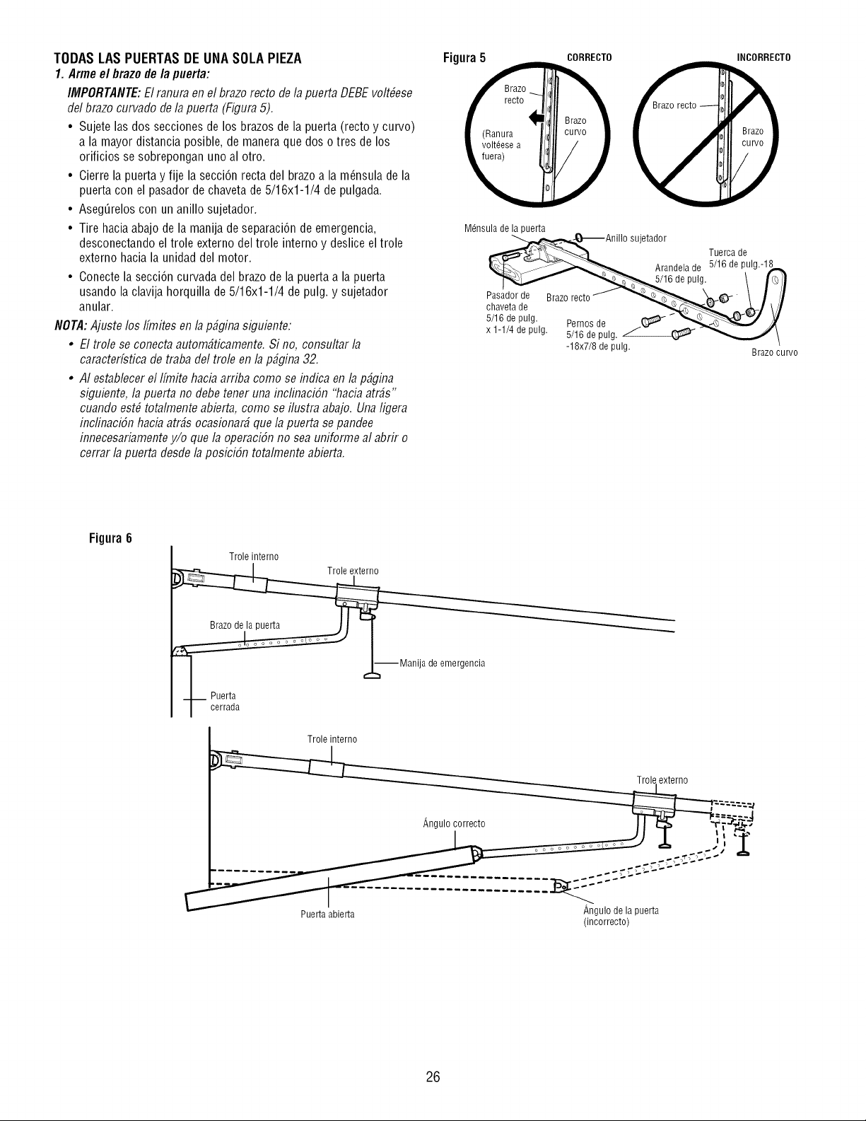
TODAS LAS PUERTAS DE UNA SOLA PIEZA
1. Arme el brazo de/a puerta:
IMPORTANTE:El ranura el7el brazorecto de la puerta DEBE volt#ese
del brazo curvado de la puerta (Figura5).
• Sujete las dos secciones de los brazos de la puerta (recto y curvo)
a la mayor distancia posible, de manera que dos o tres de los
orificios se sobrepongan uno al otro.
• Cierre la puerta y fije la secci6n recta del brazo a la m_nsula de la
puerta con el pasador de chavetade 5/16x1-1/4 de pulgada.
• Aseg_relos con un anillo sujetador.
• Tire hacia abajo de la manija de separaci6n de emergencia,
desconectando el trole externo del trole intemo y deslice el trole
externo hacia la unidad del motor.
• Conecte la secci6n curvada del brazo de la puerta a la puerta
usando la clavija horquilla de 5/16x1-1/4 de pulg. y sujetador
anular.
NOTA:Ajuste los ffmites en la p_gina siguiente:
• E/tro/e se conecta autom_ticamente. Si no, consu/tar/a
caracter[stica de traba de/tro/e en /ap_gina 32.
• A/estab/ecer e//[mite haciaarriba como se flTdicaen/a p_gina
siguiente, /a puerta no debe tener una inc/inacibn "hacia arras"
cuando est# tota/mente abierta, como se i/ustra abajo. Una /igera
inc/inaci6n haciaatr_s ocasionar_ que /a puerta sepandee
innecesariamentey/o que /a operacibn no sea uniforme a/abrir o
cerrar /a puerta desde /a posicibn tota/mente abierta.
Figura 5 CORRECTO INCORRECTO
recto
I J
Mdnsula de la puerta
_6 deAnill° sujetador
Tuerca de
Arandela de 5/16 de pulg.-18_._
ou,0.//+j/
Pasador de Brazo recto _ '",4,__------______._ 'ktt_.Q_ \ I iI
VI
x 1-1/4depul_ 5/16depulg._ -"_''_f /
-18x7/8depulg. Brazocurvo
Figura 6
Trole interno
I ,,,.L-- Manija de emergencia
Puerta
I cerrada
Trole interno
Puerta abierta
Angulode lapuerta
(incorrecto)
26
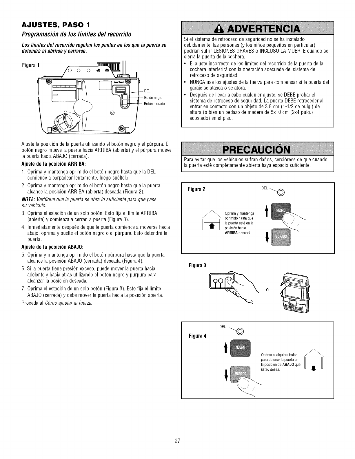
AJUSTES, PASO 1
Programaci6n de/os/imites de/recorrido
Los/imites de/recorrido regu/an /os puntos en los que/a puerta se
detendr_ al abrirse y cerrarse.
Figura1
negro
Bot6n morado
Si el sistema de retroceso de seguridad no se ha instalado
debidamente, las personas (y los niSos pequeSosen particular)
podrian sufrir LESIONESGRAVESo INCLUSOLA MUERTEcuando se
cierra la puerta de la cochera.
• El ajuste incorrecto de los limites del recorrido de la puerta de la
cochera interferir_,con la operaci6n adecuadadel sistema de
retroceso de seguridad.
• NUNCAuse los ajustes de lafuerza para compensar si la puerta del
garaje se atasca o se atora.
• Despu_s de Ilevar a cabo cualquier ajuste, se DEBEprobar el
sistema de retroceso de seguridad. La puerta DEBEretroceder al
entrar en contacto con un objeto de 3.8 cm (1-1/2 de pulg.) de
altura (o bien un pedazode madera de 5x10 cm (2x4 pulg.)
acostado) en el piso.
Ajuste la posici6n de la puerta utilizando el bot6n negro y el p_rpura. El
bot6n negro mueve la puerta hacia ARRIBA (abierta) y el p_rpura mueve
la puerta hacia ABAJO (cerrada).
Ajuste de la posici6nARRIBA:
1. Oprima y mantenga oprimido el bot6n negro hasta que la DEL
comience a parpadear lentamente, luego su61telo.
2. Oprima y mantenga oprimido el bot6n negro hasta que la puerta
alcance la posici6n ARRIBA (abierta) deseada (Figura 2).
NOTA: Verifique que la puerta se abra Io suficiente para que pase
su vehfculo.
3. Oprima el estaci6n de un solo bot6n. Esto fija el limite ARRIBA
(abierta) y comienza a cerrar la puerta (Figura3).
4. Inmediatamente despu6sde que la puerta comience a moverse hacia
abajo, oprima y suelte el bot6n negro o el p_rpura. Esto detendr_,la
puerta.
Ajuste de la posici6nABAJ0:
5. Oprima y mantenga oprimido el bot6n p_rpura hasta que la puerta
alcance la posici6n ABAJO (cerrada) deseada(Figura 4).
6. Si la puerta tiene presi6n exceso, puede mover la puerta hacia
adelentey haciaatras utilizando el boton negro y purpura para
alcanzar la posici6n deseada.
7. Oprima el estaci6n de un solo bot6n (Figura 3). Esto fija el limite
ABAJO(cerrada) y debe mover la puerta hacia la posici6n abierta.
Proceda al CSmoajustar la fuerza.
Para evitar que los vehiculos sufran daSos, cerci6rese de que cuando
la puerta est_ completamente abierta haya espacio suficiente.
Figura2 DEL
_ prima y mantenga
oprimido hasta que
lapuerta esteen la
posici6n hacia
ARRIBA deseada
t
I
Figura 3
Figura4
DEL
!
Optimacualquierabot6n
para detenerla puerta en
la posici6nde ABAJO que
usteddesea.
27
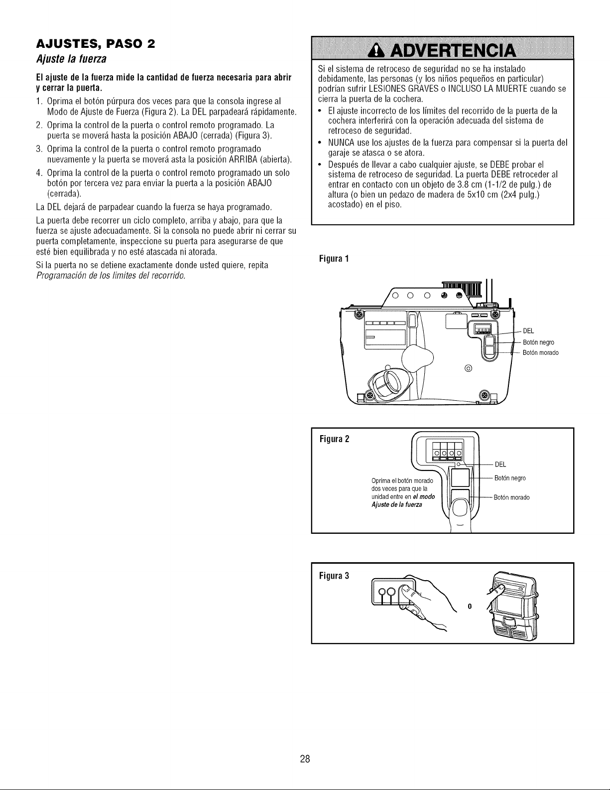
AJUSTES, PASO 2
Ajuste la fuerza
El ajuste de la fuerza mide la cantidad de fuerza necesaria para abrir
y cerrar la puerta.
1. Oprima el bot6n p_rpura dos veces para que la consola ingrese al
Modo de Ajuste de Fuerza(Figura 2). La DEL parpadear_,r_.pidamente.
2. Oprima la control de la puerta o control remoto programado. La
puerta se mover_,hasta la posici6n ABAJO (cerrada) (Figura 3).
3. Oprima la control de la puerta o control remoto programado
nuevamente y la puerta se mover_,asta la posici6n ARRIBA (abierta).
4. Oprima la control de la puerta o control remoto programado un solo
bot6n por tercera vez para enviar la puerta a la posici6n ABAJO
(cerrada).
La DEL dejar_,de parpadear cuando lafuerza se haya programado.
La puerta debe recorrer un ciclo completo, arriba y abajo, para que la
fuerza se ajuste adecuadamente.Si la consola no puedeabrir ni cerrar su
puerta completamente, inspeccione su puerta para asegurarse de que
est6 bien equilibrada y no est_ atascadani atorada.
Si la puerta no se detiene exactamente donde usted quiere, repita
ProgramaciSn de los limites del recorrido.
Si el sistema de retroceso de seguridad no se ha instalado
debidamente, las personas (y los niSos pequeSosen particular)
podrian sufrir LESIONESGRAVESo INCLUSOLA MUERTEcuando se
cierra la puerta de la cochera.
• El ajuste incorrecto de los limites del recorrido de la puerta de la
cochera interferir_,con la operaci6n adecuadadel sistema de
retroceso de seguridad.
• NUNCAuse los ajustes de lafuerza para compensar si la puerta del
garaje se atasca o se atora.
• Despu_s de Ilevar a cabo cualquier ajuste, se DEBEprobar el
sistema de retroceso de seguridad. La puerta DEBEretroceder al
entrar en contacto con un objeto de 3.8 cm (1-1/2 de pulg.) de
altura (o bien un pedazode madera de 5x10 cm (2x4 pulg.)
acostado) en el piso.
Figura1
negro
Bot6n morado
Figura2
Oprima el bot6n morado
dos veces para que la
unidad entre en el modo
A]uste de la fuerza
negro
Figura3
28
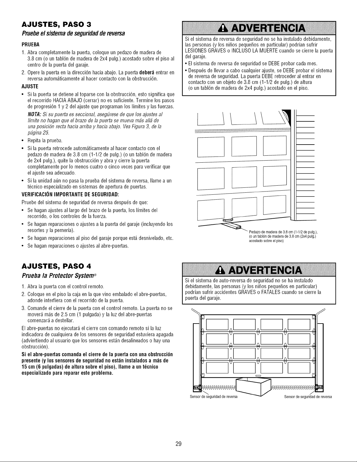
AJUSTES, PASO 3
Pruebee/sistemade seguridadde reversa
PRUEBA
1. Abra completamente la puerta, coloque un pedazode madera de
3.8 cm (o un tabl6n de madera de 2x4 pulg.) acostado sobre el piso al
centro de la puerta del garaje.
2. Opere la puerta en la direcci6n haciaabajo. La puerta deber_ entrar en
reversa autom_.ticamenteal hacer contacto con la obstrucci6n.
AJUSTE
• Si la puerta se detiene al toparse con la obstrucci6n, esto significa que
el recorrido HACIAABAJO (cerrar) no es suficiente. Termine los pasos
de progresi6n 1 y 2 del ajuste que programan los limites y las fuerzas.
NOTA:Si su puerta es seccional, asegElresede que los ajustes al
Ifmite no hagan que el brazo de lapuerta se mueva m_s all_ de
unaposici6n recta hacia arriba y hacia abajo. VeaFigura 3, de la
p#gina 25.
• Repita la prueba.
• Si la puerta retrocede autom_.ticamenteal hacer contacto con el
pedazode maderade 3.8 cm (1-1/2 de pulg.) (o un tabl6n de madera
de 2x4 pulg.), quite la obstrucci6n y abra y cierre la puerta
completamente por Io menos cuatro o cinco veces paraverificar que
el ajuste sea adecuado.
• Si la unidad a_n no pasa la prueba del sistema de reversa, Ilame a un
t_cnico especializadoen sistemas de apertura de puertas.
VERIFICACIONIMPORTANTEDESEGURIDAD:
Pruebe del sistema de seguridad de reversa despu_s de que:
• Se haganajustes al largo del brazo de la puerta, los limites del
recorrido, o los controles de la fuerza.
• Se hagan reparacioneso ajustes a la puerta del garaje (incluyendo los
resortes y la perneria).
• Se hagan reparacionesal piso del garaje porque est,. desnivelado,etc.
• Se hagan reparacioneso ajustes al abre-puertas.
Si el sistema de reversa de seguridad no se ha instalado debidamente,
las personas (y los ni_os peque_os en particular) podrian sufrir
LESIONESGRAVESo INCLUSOLA MUERTEcuando se cierre la puerta
del garaje.
• Elsistema de reversa de seguridad se DEBEprobar cada mes.
• Despu6sde Ilevar a cabo cualquier ajuste, se DEBEprobar el sistema
de reversa de seguridad. La puerta DEBEretroceder al entrar en
contacto con un objeto de 3.8 cm (1-1/2 de pulg.) de altura
(o un tabl6n de madera de 2x4 pulg.) acostado en el piso.
maderade 3.8cm (1-1/2de pulg.),
(oun tabbn de maderade 3.8 cm (2x4pulg.)
acostadosobre el piso)
AJUSTES, PASO 4
Pruebala ProtectorSystem+
1. Abra la puerta con el control remoto.
2. Coloque en el piso la caja en la que vino embalado el abre-puertas,
adonde interfiera con el recorrido de la puerta.
3. Comande el cierre de la puerta con el control remoto. La puerta no se
mover_,m_.sde 2.5 cm (1 pulgada) y la luz del abre-puertas
comenzar_,a destellar.
El abre-puertas no ejecutar_,el cierre con comando remoto si la luz
indicadora de cualquiera de los sensores de seguridad estuviera apagada
(adviertiendo al usuario que los sensores est_.ndesalineadoso hay una
obstrucci6n).
Si el abre-puertas comanda el cierre de la puerta con una obstrucci6n
presente (y los sensoresde seguridadno est_n instaladosa ms de
15 cm (6 pulgadas) de altura sobre el piso), Ilame a un t_cnico
especializado para reparar este problem.
Si el sistema de auto-reversa de seguridad no se ha instalado
debidamente, las personas (y los niSos pequeSosen particular)
podrian sufrir accidentes GRAVESo FATALEScuando se cierre la
puerta del garaje.
Sensorde seguridadde reversa Sensor de seguridadde reversa
29
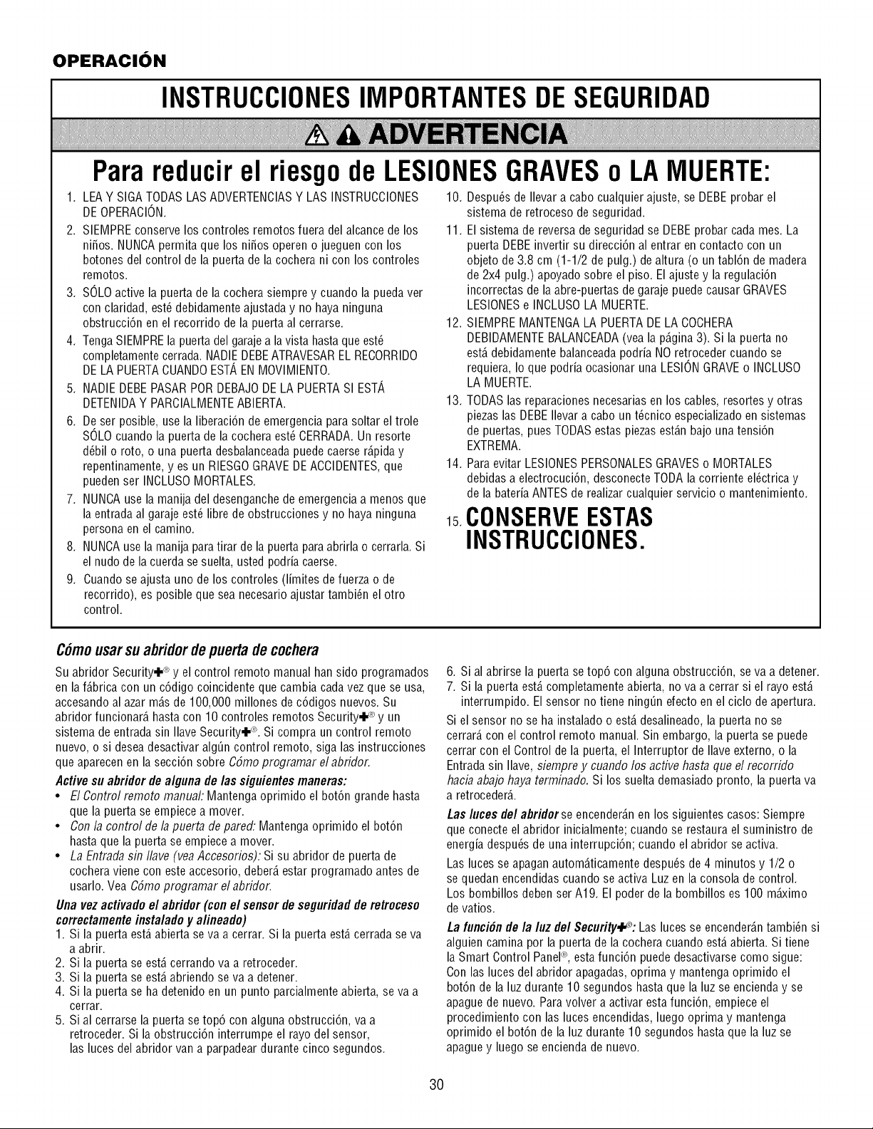
OPERACION
INSTRUCCIONESIMPORTANTESDESEGURIDAD
Para reducirel riesgo de LESIONESGRAVESo LA IViUERTE:
1. LEAY SIGATODAS LAS ADVERTENCIASY LAS INSTRUCCIONES 10. Despu6s de Ilevar a cabo cualquier ajuste, se DEBEprobar el
DEOPERACION.
2. SIEMPREconserve los controles remotos fuera del alcance de los
ni_os. NUNCApermita que los ni_os operen o jueguen con los
botones del control de la puerta de la cochera ni con los controles
remotos.
3. SOLOactive la puerta de la cochera siempre y cuando la puedaver
con claridad, est_ debidamente ajustada y no haya ninguna
obstrucci6n en el recorrido de la puerta al cerrarse.
4. TengaSIEMPREla puerta del garaje a la vista hastaque est_
completamente cerrada.NADIEDEBEATRAVESAREL RECORRIDO
DELA PUERTACUANDOESTAEN MOVIMIENTO.
5. NADIE DEBEPASARPOR DEBAJODE LA PUERTASI ESTA
DETENIDAY PARCIALMENTEABIERTA.
6. De ser posible, use la liberaci6n de emergencia para soltar el trole
SOLOcuando la puerta de la cochera est_ CERRADA.Un resorte
d6bil o roto, o una puerta desbalanceadapuede caerse r_.piday
repentinamente, yes un RIESGOGRAVEDEACCIDENTES,que
pueden ser INCLUSOMORTALES.
7. NUNCAuse la manija del desenganche de emergencia a menos que
la entrada al garaje est_ libre de obstrucciones y no haya ninguna
persona en el camino.
8. NUNCAuse la manija paratirar de la puerta paraabrirla o cerrarla. Si
el nudo de la cuerda se suelta, usted podria caerse.
9. Cuando se ajusta uno de los controles (limites de fuerza o de
recorrido), es posible que sea necesario ajustar tambi_n el otro
control.
sistema de retroceso de seguridad.
11. El sistema de reversa de seguridad se DEBEprobar cada mes. La
puerta DEBEinvertir su direcci6n al entrar en contacto con un
objeto de 3.8 cm (1-1/2 de pulg.) de altura (o un tabl6n de madera
de 2x4 pulg.) apoyado sobre el piso. El ajuste y la regulaci6n
incorrectas de la abre-puertas de garaje puede causar GRAVES
LESIONESe INCLUSOLA MUERTE.
12. SIEMPRE MANTENGALA PUERTADE LA COCHERA
DEBIDAMENTEBALANCEADA(vea la p_.gina3). Si la puerta no
est,. debidamente balanceadapodria NO retroceder cuando se
requiera, Io que podria ocasionar una LESIONGRAVEo INCLUSO
LA MUERTE.
13. TODASlas reparaciones necesarias en los cables, resortes y otras
piezas las DEBEIlevar a cabo un t_cnico especializadoen sistemas
de puertas, pues TODASestas piezasest_.nbajo una tensi6n
EXTREMA.
14. Para evitar LESIONESPERSONALESGRAVESo MORTALES
debidas a electrocuci6n, desconecte TODAla corriente el_ctrica y
de la bateria ANTESde realizar cualquier servicio o mantenimiento.
CONSERVEESTAS
INSTRUCCIONES.
C6mousarsu abridorde puerta de cochera
Su abridor Security+ ® y el control remoto manual han sido programados
en la f_.bricacon un c6digo coincidente que cambia cada vez que se usa,
accesando al azar m_.sde 100,000 millones de c6digos nuevos. Su
abridor funcionar_, hasta con 10 controles remotos Security.l-® y un
sistema de entrada sin Ilave Security.I-®. Si compra un control remoto
nuevo, o si desea desactivar alg_n control remoto, siga las instrucciones
que aparecen en la secci6n sobre CSmoprogramar elabridor.
Active su aflridor de alguna de/as siguientesmaneras:
• El Control remoto manual: Mantenga oprimido el bot6n grande hasta
que la puerta se empiece a mover.
• Con la controlde la puerta depared: Mantenga oprimido el bot6n
hasta que la puerta se empiece a mover.
• La Entradasin Ilave (vea Accesorios): Si su abridor de puerta de
cochera viene con este accesorio, deber_,estar programado antes de
usarlo. Vea CSmoprogramar el abridor.
Una vez activado el aflridor (con el sensor de seguridad de retroceso
correctamenteinsta/ado y a/ineado)
1. Si la puerta est,. abierta se va a cerrar. Si la puerta est,. cerrada se va
a abrir.
2. Si la puerta se est,. cerrando va a retroceder.
3. Si la puerta se est,. abriendo se va a detener.
4. Si la puerta se ha detenido en un punto parcialmente abierta, se va a
cerrar.
5. Sial cerrarse la puerta se top6 con alguna obstrucci6n, va a
retroceder. Si la obstrucci6n interrumpe el rayo del sensor,
las luces del abridor van a parpadeardurante cinco segundos.
6. Si al abrirse la puerta se top6 con alguna obstrucci6n, se va a detener.
7. Si la puerta est,. completamente abierta, no va a cerrar si el rayo est,.
interrumpido. El sensor no tiene ning_n efecto en el ciclo de apertura.
Si el sensor no se ha instalado o est,. desalineado, la puerta no se
cerrar_,con el control remoto manual. Sin embargo, la puerta se puede
cerrar con el Control de la puerta, el Interruptor de Ilave externo, o la
Entrada sin Ilave, siempre y cuando los active hasta que el recorrido
hacia abajo haya terminado. Si los suelta demasiado pronto, la puerta va
a retroceder&
Las luces gel abridorse encender_.nen los siguientes casos: Siempre
que conecte el abridor inicialmente; cuando se restaura el suministro de
energia despu6s de una interrupci6n; cuando el abridor se activa.
Las luces se apagan autom_.ticamentedespu6s de 4 minutos y 1/2 o
se quedan encendidas cuando se activa Luz en la consola de control.
Los bombillos deben ser A19. El poder de la bombillos es 100 m_imo
de vatios.
La funci#n de la luz de/Security._: Las luces se encender_.ntambi_n si
alguien camina por la puerta de la cochera cuando est,. abierta. Si tiene
la Smart Control Panel®, esta funci6n puededesactivarse como sigue:
Con las luces del abridor apagadas, oprima y mantenga oprimido el
bot6n de la luz durante 10 segundos hasta que la luz se encienda y se
apague de nuevo. Para volver a activar esta funci6n, empiece el
procedimiento con las luces encendidas, luego oprima y mantenga
oprimido el bot6n de la luz durante 10 segundos hasta que la luz se
apaguey luego se encienda de nuevo.
3O
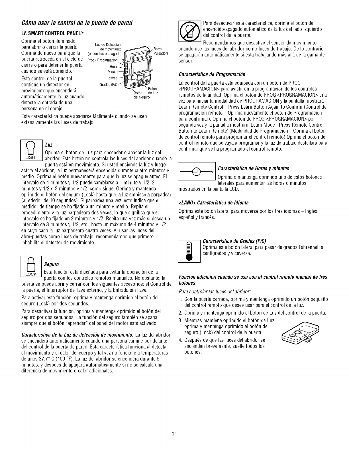
Cdmousar /a contre/de /a puerta de pared
LA SMART CONTROLPANEL®
Oprima el bot6n iluminado
para abrir o cerrar la puerta.
Oprima de nuevo para que la
puerta retroceda en el ciclo de
cierre o para detener la puerta
cuando se est,. abriendo.
Esta control de la puertal
contiene un detector de
movimiento que encender_.
autom_.ticamentela luz cuando
detecte la entrada de una
persona en el garaje.
Luz de Detecci6n
de movimiento
(encendidooapagad._ _
Prog <Programaci6n>_;_
Hora "q_ I '
Minuto
Idioma
Grados (F/C)/
_/Barra
_ Pulsadora
Bot6n
Bot6n de Luz
del Seguro
Esta caracteristica puede apagarsef_.cilmente cuando se usen
extensivamente las luces de trabajo.
L_tGHT LUZ
Oprima el bot6n de Luz paraencender o apagar la luz del
abridor. Estebot6n no controla las luces del abridor cuando la
puerta est,. en movimiento. Si usted enciende la luz y luego
activa el abridor, la luz permanecer_,encendida durante cuatro minutos y
medic. Oprima el bot6n nuevamente paraque la luz se apague antes. El
intervalo de 4 minutos y 1/2 puede cambiarse a 1 minuto y 1/2, 2
minutos y 1/2 o 3 minutos y 1/2, como sigue: Oprima y mantenga
oprimido el bot6n del seguro (Lock) hasta que la luz empiecea parpadear
(alrededor de 10 segundos). Si parpadea una vez, esto indica que el
medidor de tiempo se ha fijado a un minuto y medic. Repita el
procedimiento y la luz parpadear_,dos veces, Io que significa que el
intervalo se ha fijado en 2 minutos y 1/2. Repita una vez m_.ssi desea un
intervalo de 3 minutos y 1/2, etc., hasta un m_ximo de4 minutos y 1/2,
en cuyo caso la luz parpadear_,cuatro veces. AI usar las luces del
abre-puertas como luces de trabajo, recomendamos que primero
inhabilite el detector de movimiento.
_ eguro
Esta funci6n est,. dise5ada para evitar la operaci6n de la
• puerta con los controles remotos manuales. No obstante, la
puerta se puede abrir y cerrar con los siguientes accesorios: el Control de
la puerta, el Interruptor de Ilave externo, y la Entrada sin Ilave.
Para activar estafunci6n, oprima y mantenga oprimido el bot6n del
seguro (Lock) por dos segundos.
Para desactivar la funci6n, oprima y mantenga oprimido el bot6n del
seguro por dos segundos. La funci6n del seguro tambi_n se apaga
siempre que el bot6n "aprender" del panel del motor est6 activado.
CaracteHstica de la Luz de detecci#n de movimiento: La luz del abridor
se encender_,autom_.ticamentecuando una persona camine por delante
del control de la puerta de pared. Esta caracteristica funciona al detectar
el movimiento y el calor del cuerpo y tal vez no funcione a temperaturas
de unos 37.7° C (100 °F). La luz del abridor se encender_,durante 5
minutos, y despu_sde apagar_,autom_.ticamentesi no se calcula una
diferencia de movimiento o calor adicionales.
Para desactivar esta caracteristica, oprima el bot6n de
encendido/apagadoautom_.tico de la luz del lado izquierdo
del control de la puerta.
Recomendamos que desactive el sensor de movimiento
cuando use las luces del abridor como luces de trabajo. De Io contrario
se apagar_.nautom_.ticamentesi est,. trabajando m_.sall_.de la gama del
sensor.
Caracteristica de Programaci6n
La control de la .puertaest,.equipada con un bot6n de PROG
<PROGRAMACION>para asistir en la programaci6n de los controles
remotos de la unidad. Oprima el bot6n de PROG<PROGRAMAClON>una
vez para iniciar la modalidad de PROGRAMACIONy la pantalla mostrar_.
Learn Remote Control- Press Learn Button Again to Confirm (Control de
programaci6n remoto - Oprima nuevamente el bot6n de Programaci6n
para confirmar). Oprima el bot6n de PROG<PROGRAMACION>por
segunda vez y la pantalla mostrar_. 'Learn Mode - Press Remote Control
Button to Learn Remote' (Modalidad de Programaci6n - Oprima el bot6n
de control remoto para programar el control remoto) Oprima el bot6n del
control remoto que se vaya a programar y la luz detrabajo destellar_,para
confirmar que se ha programado el control remoto.
H--_"_--M Caracteristica de Horasy minutos
Oprima o mantenga oprimido uno de estos botones
laterales para aumentar las horas o minutos
mostrados en la pantalla LCD.
<LANG>Caracteristica de Idioma
Oprima este bot6n lateral para moverse por los tres idiomas - Ingles,
espa_ol y franc6s.
Caracteristica de Grados(F/C)
Oprima estebot6n lateral para pasar de grados Fahrenheita
centigrados y viceversa.
FunciOnadicionalcuandose usa conel controlremotomanualdetres
botones
Para controiar /as luces del abridor:
1. Con la puerta cerrada, oprima y mantenga oprimido un bot6n peque_o
del control remoto que desee usar para el control de la luz.
2. Oprima y mantenga oprimido el bot6n de Luzdel control de la puerta.
3. Mientras mantiene oprimido el bot6n de Luz,
oprima y mantenga oprimido el bot6n del
seguro (Lock) del control de la puerta.
4. Despu_s de que las luces del abridor se
enciendan brevemente, suelte todos los
botones.
31
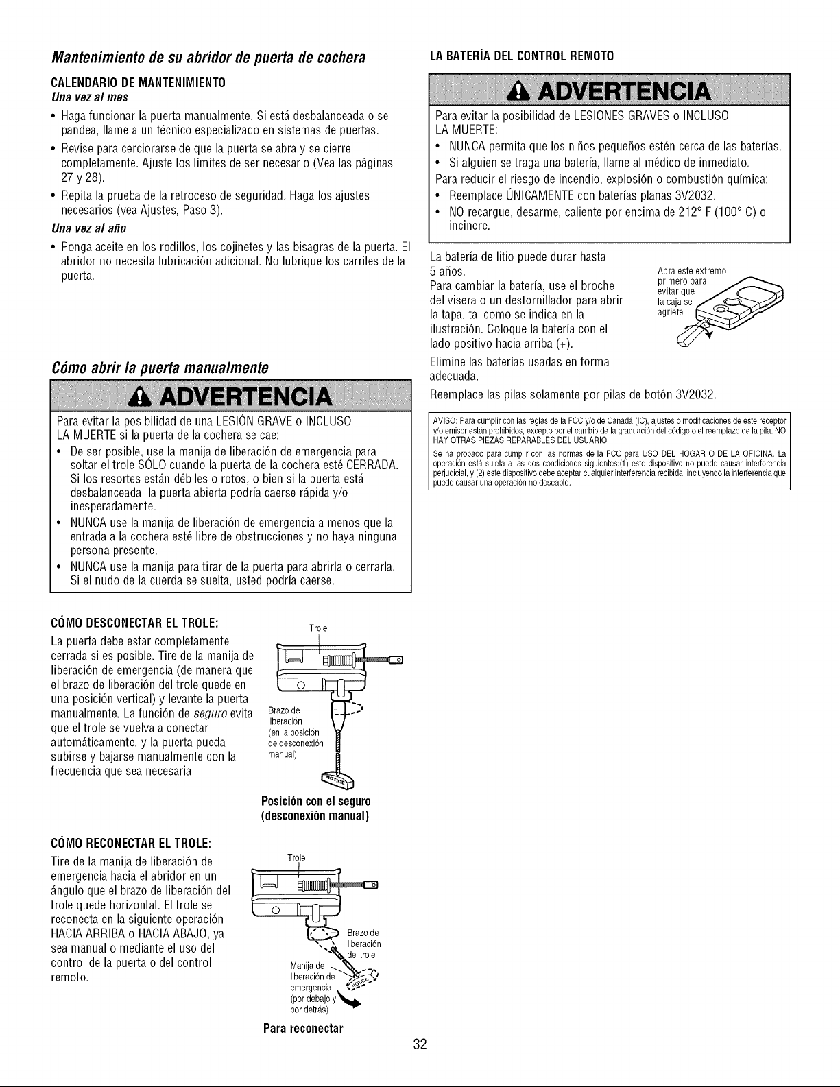
Mantenimiento de su abridor de puerta de cochera
CALENDARIODE MANTENliVIIENTO
Una vez al mes
• Hagafuncionar la puerta manualmente Si est_ desbalanceadao se
pan@a, Ilamea un t@nico especializadoen sistemas de puertas
• Revise para cerciorarse de que la puerta se abra y se cierre
completamente. Ajuste los limites de ser necesario (Vea las p_.ginas
27 y 28).
• Repita la prueba de la retroceso de seguridad. Haga los ajustes
necesarios (vea Ajustes, Paso 3).
Una vez al a#o
• Pongaaceite en los rodillos, loscojinetes y las bisagras de la puerta El
abridor no necesita lubricaci6n adicional. No lubrique los carriles de la
puerta.
C6moabrir la puerta manualmente
Para evitar la posibilidad de una LESIONGRAVEo INOLUSO
LA MUERTEsi la puerta de la cochera se cae:
• De ser posible, use la manila de liberaci6n de emergencia para
soltar el trole SOLOcuando la puerta de la cochera est_ CERRADA.
Si los resortes est_.nd_biles o rotos, o bien si la puerta est,.
desbalanceada,la puerta abierta podria caerse r_.piday/o
inesperadamente.
• NUNCAuse la manila de liberaci6n de emergencia a menos que la
entrada a la cochera est_ libre de obstrucciones y no haya ninguna
persona presente.
• NUNCAuse la manila para tirar de la puerta para abrirla o cerrarla.
Si el nudo de la cuerda se suelta, usted podria caerse.
LA BATERIADEL CONTROLREMOTO
Para evitar la posibilidad de LESIONESGRAVESo INCLUSO
LA MUERTE:
• NUNCApermita que los n 5os pequeSosest_n cerca de las baterias.
• Si alguien setraga una bateria, Ilame al m_dico de inmediato.
Para reducir el riesgo de incendio, explosi6n o combusti6n quimica:
• Reemplace UNICAMENTEcon baterias planas 3V2032.
• NO recargue, desarme, caliente por encima de 212° F (100° C) o
incinere.
La bateria de litio puede durar hasta
5 aSos.
Para cambiar la bateria, use el broche
del visera o un destornillador para abrir
la tapa, tal como se indica en la
ilustraci6n. Coloque la bateria con el
lado positivo hacia arriba (+).
Elimine las baterias usadas en forma
adecuada.
Abra este extremo
primero para
evitar que J ('-
la caja se _..._._/-"---_-,._/j'
agrle_
Reemplace las pilas solamente por pilas de bot6n 3V2032.
AVISO: Para cumplir con las reglas de la FCC y/o de Canada (IC). ajustes o modificaciones de este receptor I
y/e emiser estan prehibides, excepte per el cambie de la graduaci6n del c6dige e el reemplaze de la pila. NO I
HAY OTRAS PIEZAS REPARABLES DEL USUARIO I
Se ha prebade para cutup r con las nermas de la FCC para USO DEL HOGAR O DE LA OFICINA. La
operaci6n est,1 sujeta a las des cendicienes siguientes:(1) este dispesitive no puede causar interferencia I
perjudicial, y (2) este dispesitivo debe aceptar cualquier interferencia recibida, incluyendo la interferencia que
puede causar una operac 6n no deseab e.
COMO DESCONECTARELTROLE:
La puerta debe estar completamente
cerrada si es posible. Tire de la manila de
liberaci6n de emergencia (de maneraque
el brazo de liberaci6n del trole quede en
una posici6n vertical) y levante la puerta
manualmente. La funci6n de seguro evita
que el trole se vuelvaa conectar
autom_.ticamente,y la puerta pueda
subirse y bajarse manualmente con la
frecuencia que sea necesaria.
COMO RECONECTARELTROLE:
Tire de la manila de liberaci6n de
emergencia hacia el abridor en un
_.nguloque el brazo de liberaci6n del
trole quede horizontal. El trole se
reconecta en la siguiente operaci6n
HACIAARRIBA o HACIAABAJO,ya
sea manual o mediante el uso del
control de la puerta o del control
remoto.
Trole
de desconexi6n
manual)
PosiciOnconel seguro
(desconexiOn manual)
Trole
". _ liberacidn
"'% del trole
Manila de _ _ __
,iberaci6nde'_,_'
emergencia _. ,._-"
(por debajo y_
par detras)
Parareconectar
32
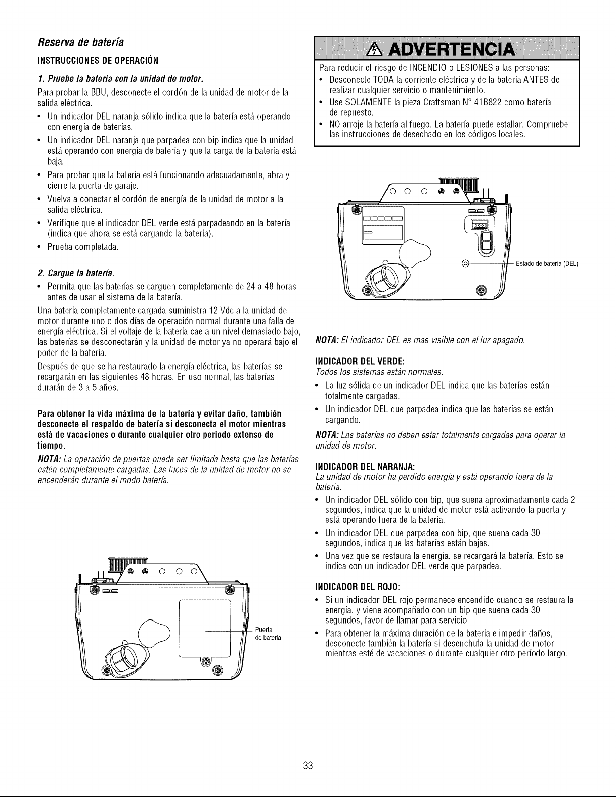
Reservade bateria
INSTRUCCIONESDE OPERACION
1. Pruebe /a bateria con/a unidad de motor.
Para probar la BBU, desconecte el cord6n de la unidad de motor de la
salida ebctrica.
• Un indicador DEL naranja s61ido indica que la bateria est,. operando
con energia de baterias.
• Un indicador DEL naranja que parpadea con bip indica que la unidad
est,. operando con energia de bateria y que la carga de la bateria est,.
baja.
• Para probar que la bateria est,.funcionando adecuadamente,abra y
cierre la puerta de garaje.
• Vuelva a conectar el cord6n de energia de la unidad de motor a la
salida el_ctrica.
• Verifique que el indicador DELverde est,. parpadeandoen la bateria
(indica que ahora se est,. cargando la bateria).
• Prueba completada.
2. Cargue/a bateria.
• Permita que las baterias se carguen completamente de 24 a 48 horas
antes de usar el sistema de la bateria.
Una bateria completamente cargada suministra 12 Vdc a la unidad de
motor durante uno o dos dias de operaci6n normal durante unafalla de
energia ebctrica. Si el voltaje de la bateria cae a un nivel demasiado bajo,
las baterias se desconectar_.ny la unidad de motor ya no operar_,bajo el
poder de la bateria.
Despu6s de que se ha restaurado la energia el_ctrica, las baterias se
recargar_.nen las siguientes 48 horas. En uso normal, las baterias
durar_.nde 3 a 5 aSos.
Para obtener la vida m_xima de la bateria y evitar dafio, tambi_n
desconecteel respaldo de bateria si desconectael motor mientras
est_ de vacaciones o durantecualquier otro periodo extensode
tiempo.
NOTA:La operaci6n de puertas puede ser limitada hasta que las baterfas
est#n completamente cargadas.Las luces de la unidad de motor no se
encender#n durante el modo baterfa.
Puerta
de bateria
Para reducir el riesgo de INCENDIOo LESIONESa las personas:
• DesconecteTODA la corriente el_ctrica y de la bateria ANTESde
realizar cualquier servicio o mantenimiento.
• Use SOLAMENTEla pieza Craftsman N° 41B822 como bateria
de repuesto.
• NO arroje la bateria al fuego. La bateria puede estallar. Compruebe
las instrucciones de desechado en los c6digos locales.
@
Estado de bateria (DEL)
NOTA:El indicador DELes mas visible con el luz apagado.
INDICADORDELVERDE:
Todoslos sistemas est#n normales.
• La luz s61idade un indicador DEL indica que las baterias est_.n
totalmente cargadas.
• Un indicador DEL que parpadeaindica que las baterias se est_.n
cargando.
NOTA:Las baterfas no deben estar totalmente cargadas para operar la
unidad de motor.
INDICADORDEL NARANJA:
La unidad de motor ha perdido energfay est_ operando fuera de la
baterfa.
• Un indicador DEL s61idocon hip, que suena aproximadamente cada 2
segundos, indica que la unidad de motor est,. activando la puerta y
est,. operando fuera de la bateria.
• Un indicador DEL que parpadeacon bip, que suena cada30
segundos, indica que las baterias est_.nbajas.
• Una vez que se restaura la energia, se recargar_,la bateria. Esto se
indica con un indicador DEL verde que parpadea.
INDICADORDELROJO:
• Si un indicador DEL rojo permanece encendido cuando se restaura la
energia, y viene acompaSado con un bip que suena cada30
segundos, favor de Ilamar para servicio.
• Para obtener la m_.ximaduraci6n de la bateria e impedir da5os,
desconecte tambi_n la bateria si desenchufa la unidad de motor
mientras est_ de vacaciones o durante cualquier otro periodo largo.
33
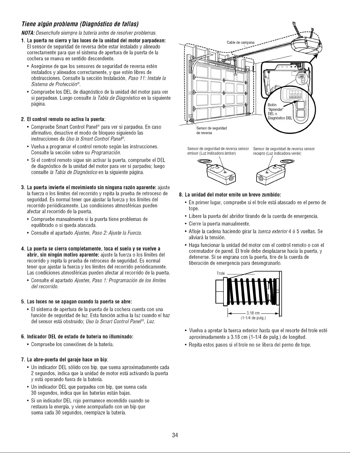
Tienealg#n prob/ema (Diagn6sticode fa//as)
NOTA:Desenchufe siempre la baterfa antes de resolver problemas.
1. La puertano cierra y las luces de la unidaddel motor parpadean:
El sensor de seguridad de reversa debe estar instalado y alineado
correctamente para que el sistema de apertura de la puerta de la
cochera se mueva en sentido descendente.
• Aseg_rese de que los sensores de seguridad de reversa est6n
instalados y alineados correctamente, y que est6n libres de
obstrucciones. Consulte la secci6n Instalaci6n, Paso 11: Instale la
Sistema de Protecci617_.
• Compruebe los DEL de diagn6stico de la unidad del motor para ver
si parpadean. Luego consulte la Tabla de Diagn6stico en la siguiente
p_.gina.
2. El controlremoto no activa la puerta:
• Compruebe Smart Control Panel® para ver si parpadea. En caso
afirmativo, desactive el modo de bloqueo siguiendo las
instrucciones de Uso /a Smart Control PaneP.
• Vuelva a programar el control remoto seg_n las instrucciones.
Consulte la secci6n sobre su Programaci6n.
• Si el control remoto sigue sin activar la puerta, compruebe el DEL
de diagn6stico de la unidad del motor para ver si parpadea;luego
consulte/a Tab/ade Diagn6stico en la siguiente p_.gina.
3. La puerta invierte el movimiento sin ninguna raz6n aparente: ajuste
la fuerza o los limites del recorrido y repita la prueba de retroceso de
seguridad. Es normal tener que ajustar la fuerza y los limites del
recorrido peri6dicamente. Las condiciones atmosf6ricas pueden
afectar al recorrido de la puerta.
• Compruebe manualmente si la puerta tiene problemas de
equilibrado o si queda atascada.
• Consulte el apartado Ajustes, Paso 2: Ajuste/a Fuerza.
4. La puertase cierra completamente,toca el suelo y se vuelve a
abrir, sin ning_n motivo aparente: ajuste lafuerza o los limitesdel
recorrido y repita la prueba de retroceso de seguridad. Es normal
tener que ajustar lafuerza y los limites del recorrido peri6dicamente.
Las condiciones atmosf6ricas pueden afectar al recorrido de la puerta.
• Consulte el apartado Ajustes, Paso 1: ProgramaciSn de los Iflnites
del recorrido.
iv
i
Sensor de seguridad
de reversa
Cable de campana
)
Sensor de seguridad de reversa sensor Sensor de seguridad de reversa sensor
emisor (Luz indicadora _mbar) recepto (Luz indicadora verde)
8. La unidaddel motor emite un breve zumbido:
• En primer lugar, compruebe si el trole est,. atascado en el perno de
tope.
• Libere la puerta del abridor tirando de la cuerda de emergencia.
• Cierre la puerta manualmente.
• Afloje la cadena haciendo girar la tuerca exterior4 6 5 vueltas. Se
aliviar_,la tensi6n.
• Haga funcionar la unidad del motor con el control remoto o con el
conmutador de pared. El trole debe desplazarse hacia la puerta, y
detenerse. Si se engranacon la puerta, tire de la cuerda de
liberaci6n de emergencia para desengranarlo.
Trole --
5. Las luces no se apagancuando la puerta se abre:
• El sistema de apertura de la puerta de la cochera cuenta con una
funci6n de seguridad de luz. Estafunci6n activa la luz cuando el haz
del sensor est,. obstruido; Uso la Smart Control Panel®,Luz.
6. IndicadorDELdeestadode bateriano illuminado:
• Compruebelos conexi6nesde la bateria.
1_ 3.18
(1-1/4 de pulg.)
• Vuelva a apretar la tuerca exterior hasta que el resorte del trole est6
aproximadamente a 3.18 cm (1-1/4 de pulg.) de Iongitud.
• Repita estos pasos si el trole no se libera del perno de tope.
7. La abre-puerta del garaje hace un bip:
• Un indicador DEL s61idocon bip, que suena aproximadamente cada
2 segundos, indicaque la unidad de motor est,. activando la puerta
y est,. operando fuera de la bateria.
• Un indicadorDEL que parpadea con bip, que suena cada
30 segundos, indica que las baterias est_.nbajas.
• Si un indicador DEL rojo permanece encendido cuando se
restaura la energia, y viene acompaSado con un bip que
suena cada30 segundos, reemplazela bateria.
34
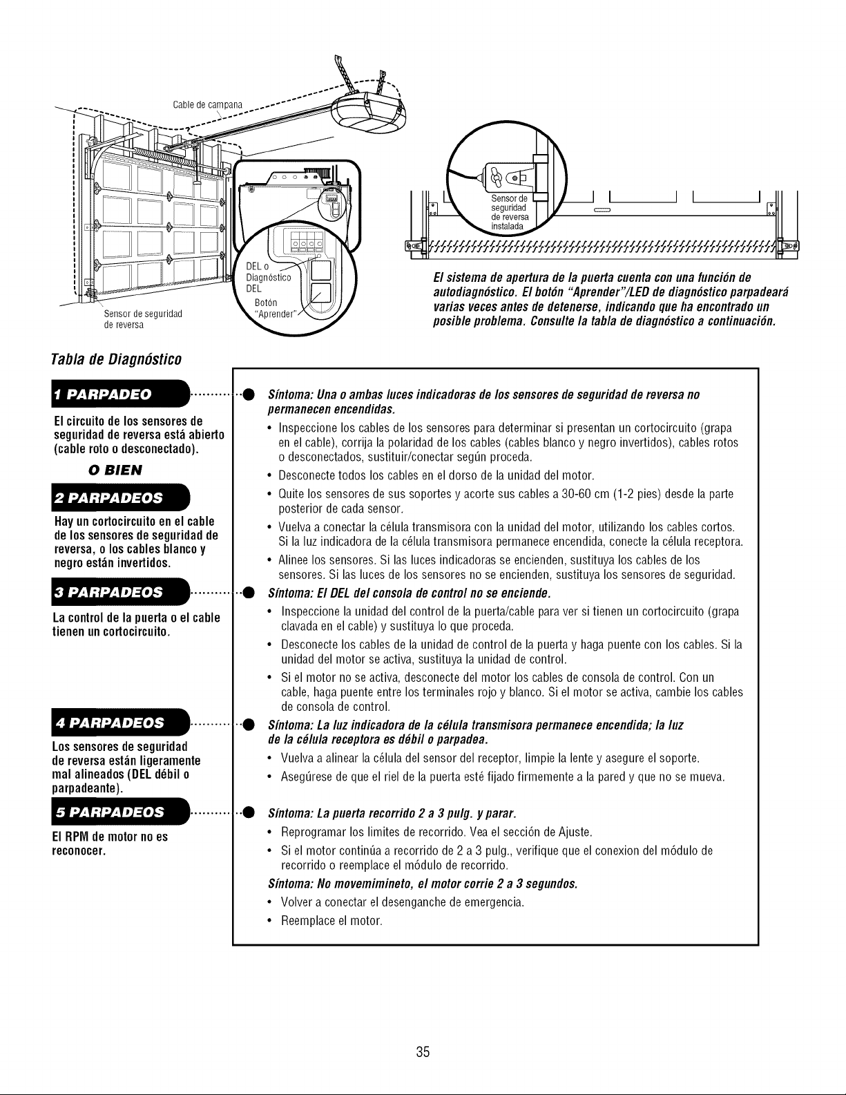
Cable de campana
\
Sensor de seguridad
de reversa
El sistema de apertura de/a puerta cuenta con una funci6n de
autodiagn6stico.El bot6n "Aprender'/LED de diagn6sticoparpadear_
varias veces antes de detenerse, indicandoque ha encontradoun
posib/e prob/ema. Consu/te/a tab/a de diagn6sticoa continuaci6n.
Tabla de Diagn6stico
Elcircuitodelos sensoresde
seguridaddereversaest_abierto
(cablerotoo desconectado).
0 BIEN
Hayuncortocircuitoenel cable
delossensoresdeseguridadde
reversa,o loscablesblancoy
negroest_ninvertidos.
Lacontrolde lapuertao el cable
tienenuncortocircuito.
Lossensoresdeseguridad
de reversaest_nligeramente
realalineados(DELd_bilo
parpadeante).
ElRPMde motornoes
reconocer.
•"0 Sintoma: Una o ambas luces indicadorasde los sensores de seguridad de reversa no
permanecen encendidas.
• Inspeccione los cables de los sensores para determinar si presentan un cortocircuito (grapa
en el cable), corrija la polaridad de los cables (cables blanco y negro invertidos), cables rotos
o desconectados, sustituir/conectar seg_n proceda.
• Desconectetodos los cables en el dorso de la unidad del motor.
• Quite los sensores de sus soportes y acorte sus cables a 30-60 cm (1-2 pies) desde la parte
posterior de cada sensor.
• Vuelva a conectar la c_lula transmisora con la unidad del motor, utilizando los cables cortos.
Si la luz indicadora de la c_lula transmisora permanece encendida, conecte la c61ulareceptora.
• Alinee los sensores. Si las luces indicadoras se encienden,sustituya los cables de los
sensores. Si las luces de los sensores no se encienden, sustituya los sensores de seguridad.
•"0 Sfntoma: El DELdel consola de control no se enciende.
• Inspeccione la unidad del control de la puerta/cable para ver si tienen un cortocircuito (grapa
clavada en el cable) y sustituya Io que proceda.
• Desconectelos cables de la unidad de control de la puerta y haga puente con los cables. Si la
unidad del motor se activa, sustituya la unidad de control.
• Si el motor no se activa, desconecte del motor los cables de consola de control. Con un
cable, haga puente entre los terminales rojo y blanco. Si el motor se activa, cambie los cables
de consola de control.
•"0 Sintoma: La luz indicadora de la c61ula transmisorapermanece encendida; la luz
de la c#lula receptoraes d_bil o parpadea.
• Vuelva a alinear la c_lula del sensor del receptor, limpie la lente y asegure el soporte.
• Aseg_rese de que el riel de la puerta est6fijado firmemente a la pared y que no se mueva.
..e
Sintoma: La puerta recorrido 2 a 3 pulg. y parar.
• Reprogramar los limites de recorrido Vea el secci6n de Ajuste
• Si el motor continua a recorrido de 2 a 3 pulg, verifique que el conexion del m6dulo de
recorrido o reemplaceel m6dulo de recorrido.
Sintoma: No movemimineto, el motor corrie 2 a 3 segundos.
• Volver a conectar el desenganchede emergencia
• Reemplaceel motor.
35
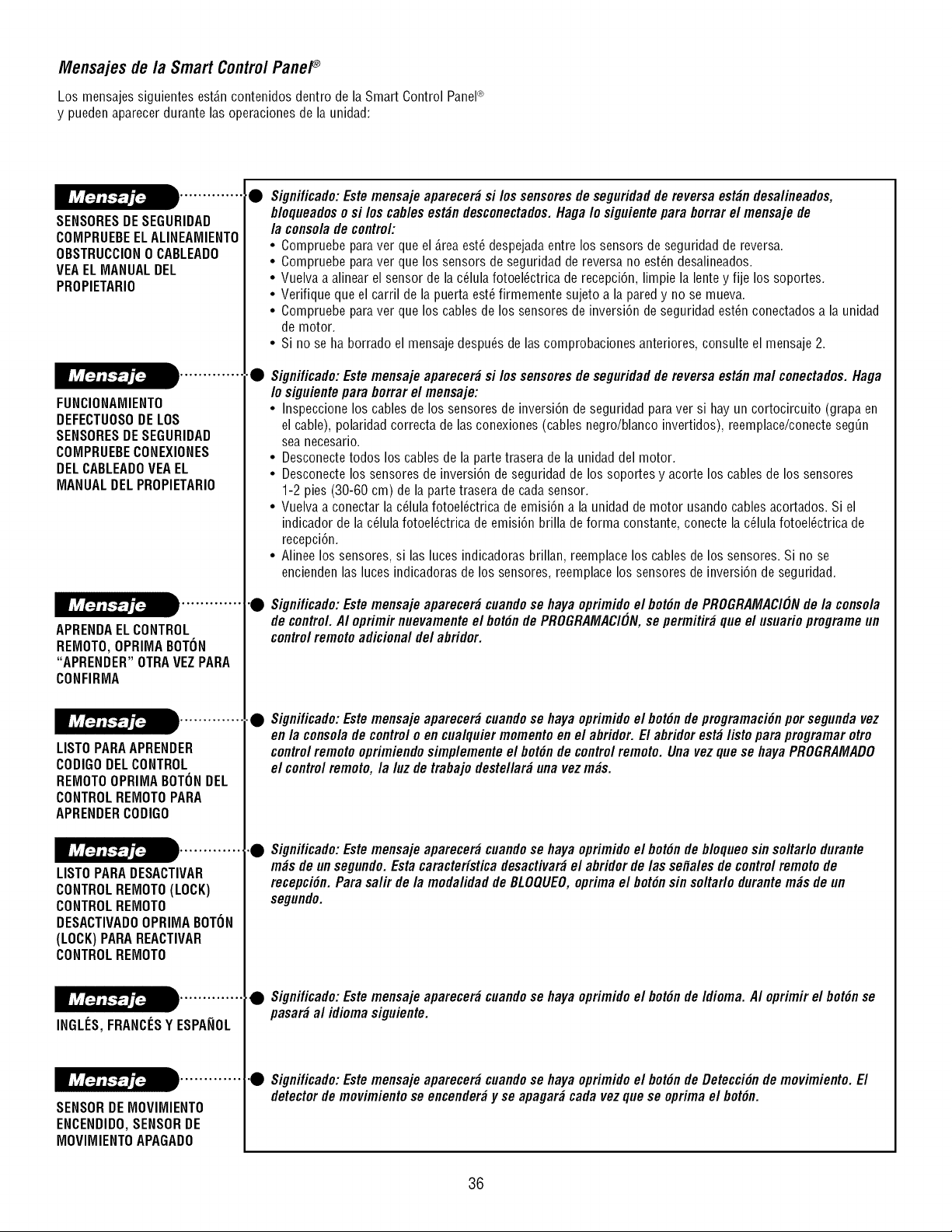
Mensajes de/a Smart ControlPaneP
Los mensajessiguientes est_.ncontenidos dentro de la Smart Control PaneP
y pueden aparecer durante las operaciones de la unidad:
SENSORESDE SEGURIDAD
COMPRUEBEELALINEAMIENTO
OBSTRUCCION0 CABLEADO
VEAEL MANUAL DEL
PROPIETARIO
FUNCIONAMIENTO
DEFECTUOSODELOS
• Significado:Este mensaje aparecer# si los sensores de seguridad de reversa est#n desa/ineados,
b/oqueadoso si los cables est#n desconectados.Haga /o siguiente para borrarel mensaje de
/a conso/ade control:
• Compruebe para ver que el Area est_ despejada entre los sensors de seguridad de reversa.
• Compruebe para ver que los sensors de seguridad de reversa no est_n desalineados.
• Vuelva a alinear el sensor de la c_lula fotoel_ctrica de recepci6n, limpie la lente y fije los soportes.
• Verifique que el carril de la puerta est_firmemente sujeto a la pared y no se mueva.
• Compruebe para ver que los cables de los sensores de inversi6n de seguridad est_n conectados a la unidad
de motor.
• Si no se ha borrado el mensaje despu_s de las comprobaciones anteriores, consulte el mensaje 2.
SENSORESDE SEGURIDAD
COMPRUEBECONEXIONES
DEL CABLEADOVEAEL
MANUAL DEL PROPIETARIO
APRENDAELCONTROL
REMOTO,OPRIMABOTON
"APRENDER"OTRAVEZPARA
CONFIRMA
LISTOPARAAPRENDER
CODIGODELCONTROL
REMOTOOPRIMABOTONDEL
CONTROLREMOTOPARA
APRENDERCODIGO
LISTOPARADESACTIVAR
CONTROLREMOTO(LOCK)
CONTROLREMOTO
DESACTIVADOOPRIMA BOTON
(LOCK) PARAREACTIVAR
CONTROLREMOTO
INGLI_S,FRANCI_SY ESPA_IOL
SENSORDE MOVIMIENTO
ENCENDIDO,SENSORDE
MOVIMIENTOAPAGADO
Significado:Este mensaje aparecer# si los sensores de seguridad de reversa est#n mal conectados.Haga
/o siguientepara borrar el mensaje:
• Inspeccione los cables de los sensores de inversi6n de seguridad para ver si hay un cortocircuito (grapa en
el cable), polaridad correcta de las conexiones (cables negro/blanco invertidos), reemplace/conecte segQn
sea necesario.
• Desconectetodos los cables de la parte trasera de la unidad del motor.
• Desconecte los sensores de inversi6n de seguridad de los soportes y acorte los cables de los sensores
1-2 pies (30-60 cm) de la parte trasera de cada sensor.
• Vuelva a conectar la c_lula fotoel_ctrica de emisi6n a la unidad de motor usando cables acortados. Si el
indicador de la c_lula fotoel_ctrica de emisi6n brilla de forma constante, conecte la c_lula fotoel_ctrica de
recepci6n.
• Alinee los sensores, si las luces indicadoras brillan, reemplace los cables de los sensores. Si no se
encienden las luces indicadoras de los sensores, reemplace los sensores de inversi6n de seguridad.
•• Significado:Este mensaje aparecer# cuandose haya oprimidoel bot#n de PROGRAMACIONde/a conso/a
de control. A/ oprimir nuevamenteel bot#n de PROGRAMACION,se permitir# que el usuario programe un
controlremote adiciona/ de/ abridor.
• Significado:Estemensajeaparecer_cuandose hayaoprimidoel bot6ndepmgramaci6npot segundavez
enla consoladecontrolo encualquiermomentoenel abridor.El abridorest_ listoparapmgramarotto
controlremoteoprimiendosimplementeel bot6ndecontrolremote. Unavezquese hayaPROGRAMADO
el controlremoto,la luzdetrabajodestellar_unavezm_s.
.• Significado:Este mensaje aparecer# cuandose haya oprimidoel bot#n de b/oqueosin so/tar/o durante
m#s de un segundo. Esta caracteristica desactivar#el abridor de/as sefa/es de control remoto de
recepci#n. Para sa/ir de/a moda/idad de BLOQUEO,optima el bot#n sin so#aflo durantem#s de un
segundo.
• Significado:Este mensaje aparecer# cuandose haya oprimidoel bot#nde Idioma. AI oprimir el bot#n se
pasar# a/ idioma siguiente.
•• Significado:Estemensajeaparecer_cuandose hayaoprimidoel bot6nde Detecci6ndemovimiento.El
detectorde movimientose encender_y se apagar_cadavezquese optima el bot6n.
36
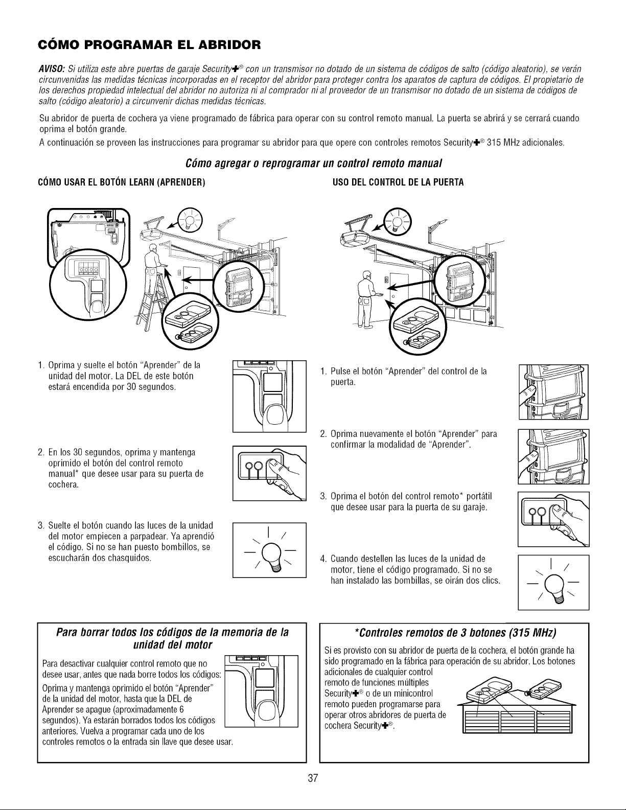
COMO PROGRAMAR EL ABRIDOR
A VISO:Si utiliza este abre puertas de garaje Secufity,I._ con un transmisor no dotado de un sistema de cSdigos de salto (cSdigo aleatorio), se verst7
circunvenidas las medidas t#cnicas incorporadas en el receptor del abridor para proteger contra los aparatos de captura de cSdigos. Elpropietario de
los derechos propiedad intelectual del abridor no autoriza ni al comprador ni al proveedor de un transmisor no dotado de un sistema de cSdigos de
salto (cSdigoaleatorio) a circunvenir dichas medidas t#cnicas.
Su abridor de puerta de cochera ya viene programado de f_.bricaparaoperar con su control remoto manual. La puerta se abrir_,y se cerrar_,cuando
oprima el bot6n grande.
A continuaci6n se proveen las instrucciones para programar su abridor para que opere con controles remotos Security.I-<_315 MHz adicionales.
C6mo agregaro reprogramarun contro/remotomanua/
COMO USAREL BOTONLEARN(APRENDER) USO DELCONTROLDE LA PUERTA
1. Oprima y suelte el bot6n "Aprender" de la
unidad del motor. La DEL de este bot6n
estar_,encendida por 30 segundos.
2. En los 30 segundos, oprima y mantenga
oprimido el bot6n del control remoto
manual* que desee usar para su puerta de
cochera.
3. Suelte el bot6n cuando las luces de la unidad
del motor empiecen a parpadear. Ya aprendi6
el c6digo. Si no se han puesto bombillos, se
escuchar_.ndos chasquidos.
I /
1. Pulse el bot6n "Aprender" del control de la
puerta.
2. Oprima nuevamente el bot6n "Aprender" para
confirmar la modalidad de "Aprender".
3. Oprima el bot6n del control remoto* port_.til
que desee usar para la puerta de su garaje.
4. Cuando destellen las luces de la unidad de
motor, tiene el c6digo programado. Si no se
han instalado las bombillas, se oir_.n dos clics.
\1 /
Para borrar todos/os c6digosde/a memoria de la
unidad de/motor
Paradesactivarcualquiercontrol remoto que no
deseeusar,antes quenada borretodos los c6digos:
Oprimay mantengaoprimido el bot6n"Aprender"
de launidaddel motor, hastaque laDELde
Aprenderse apague(aproximadamente6
segundos).Ya estar_.nborradostodos los c6digos
anteriores.Vuelvaa programar cadauno de los
controlesremotos o la entradasin Ilaveque deseeusar.
*Contro/es remotos de 3 botones (315 MHz)
Si es provisto con su abridor de puertade la cochera,el bot6n grande ha
sido programadoen la f_.bricaparaoperaci6n de su abridor. Losbotones
adicionalesde cualquiercontrol
remoto de funciones m_ltiples _ _
Security+<_*o de un minicontrol
remoto puedenprogramarsepara
operarotros abridoresde puertade
cocheraSecurity,_L
37
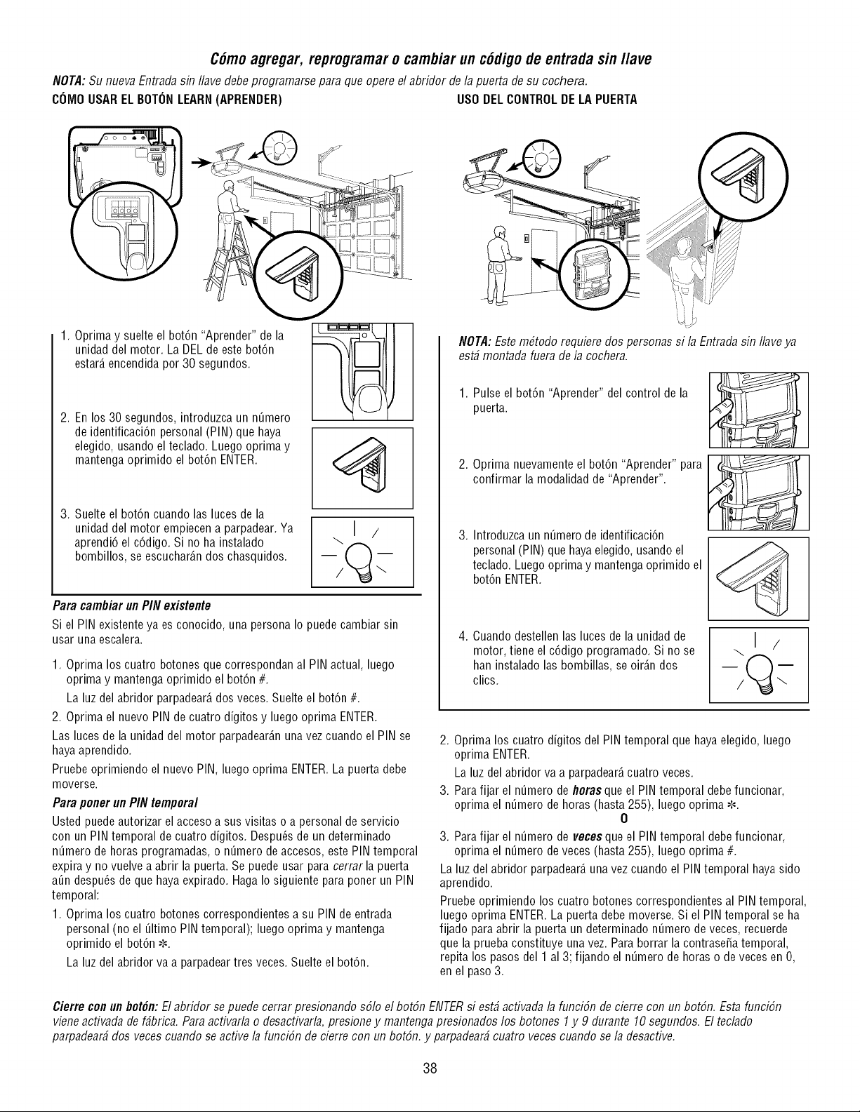
C6moagregar, reprogramaro cambiar un cddigode entradasin/lave
NOTA:Su nueva Entrada sin Ilave debe programarse para que opere el abridor de la puerta de su cochera.
COMO USAREL BOTONLEARN(APRENDER) USO DELCONTROLDE LA PUERTA
1. Oprima y suelte el bot6n "Aprender" de la
unidad del motor. La DEL de este bot6n
estar_,encendida por 30 segundos.
2. En los 30 segundos, introduzca un nQmero
de identificaci6n personal (PIN) que haya
elegido, usando el teclado. Luego oprima y
mantenga oprimido el bot6n ENTER.
3. Suelte el bot6n cuando las luces de la
unidad del motor empiecen a parpadear.Ya
aprendi6 el c6digo. Si no ha instalado
bombillos, se escuchar_.ndos chasquidos.
Para cambiar un PIN existente
Si el PIN existente ya es conocido, una persona Io puede cambiar sin
usar una escalera.
1. Oprima los cuatro botones que correspondan al PIN actual, luego
oprima y mantenga oprimido el bot6n #.
La luz del abridor parpadear_,dos veces. Suelte el bot6n #.
2. Oprima el nuevo PIN de cuatro digitos y luego oprima ENTER.
Las luces de la unidad del motor parpadear_.nunavez cuando el PIN se
haya aprendido.
Pruebe oprimiendo el nuevo PIN, luego oprima ENTER.La puerta debe
moverse.
Para porter un PIN temporal
Usted puede autorizar el acceso a sus visitas o a personal de servicio
con un PIN temporal de cuatro digitos. Despu6s de un determinado
n_mero de horas programadas, o n_mero de accesos, este PIN temporal
expira y no vuelve a abrir la puerta. Se puede usar para cerrar la puerta
a_n despu6s de que haya expirado. Haga Io siguiente para poner un PIN
temporal:
1. Oprima los cuatro botones correspondientes a su PIN de entrada
personal (no el _ltimo PIN temporal); luego oprima y mantenga
oprimido el bot6n _-'.
La luz del abridor va a parpadeartres veces. Suelte el bot6n.
)
NOTA:Este m_todo requiere dos personas si la Entrada sin Ilave ya
est_ montada fuera de la cochera.
1. Pulse el bot6n "Aprender" del control de la
puerta.
2. Oprima nuevamente el bot6n "Aprender" para
confirmar la modalidad de "Aprender".
3. Introduzca un n_mero de identificaci6n
personal (PIN) que hayaelegido, usandoel
teclado. Luego oprima y mantenga oprimido el
bot6n ENTER.
4. Cuando destellen las luces de la unidad de
motor, tiene el c6digo programado. Si no se
han instalado las bombillas, se oir_.ndos
clics.
\1 /
2. Oprima los cuatro digitos del PIN temporal que haya elegido, luego
oprima ENTER.
La luz del abridor va a parpadear_,cuatro veces.
3. Para fijar el n_mero de horas que el PIN temporal debe funcionar,
oprima el n_mero de horas (hasta 255), luego oprima -','-'.
0
3. Para fijar el n_mero de veces que el PINtemporal debe funcionar,
oprima el n_mero de veces (hasta 255), luego oprima #.
La luz del abridor parpadear_,una vez cuando el PIN temporal haya sido
aprendido.
Pruebe oprimiendo los cuatro botones correspondientes al PIN temporal,
luego oprima ENTER.La puerta debe moverse. Si el PIN temporal se ha
fijado para abrir la puerta un determinado n_mero de veces, recuerde
que la prueba constituye una vez. Para borrar la contrase5a temporal,
repita los pasos del 1 al 3; fijando el n_mero de horas o de veces en O,
en el paso 3.
Cierre con un bot6n: El abridor se puede cerrar presionando sS/oel botSn ENTERsi est# acfivada /a funciSn de cierre con un botSn. Esta funciSn
vieneacfivada de f#brica. Para acfivar/a o desactivar/a,presione y mantenga presionados /os botones 1y 9 durante 10 segundos. El tec/ado
parpadear# dos veces cuando se active/a funciSn de cierre con un botSn,y parpadear# cuatro veces cuando se /a desactive.
38
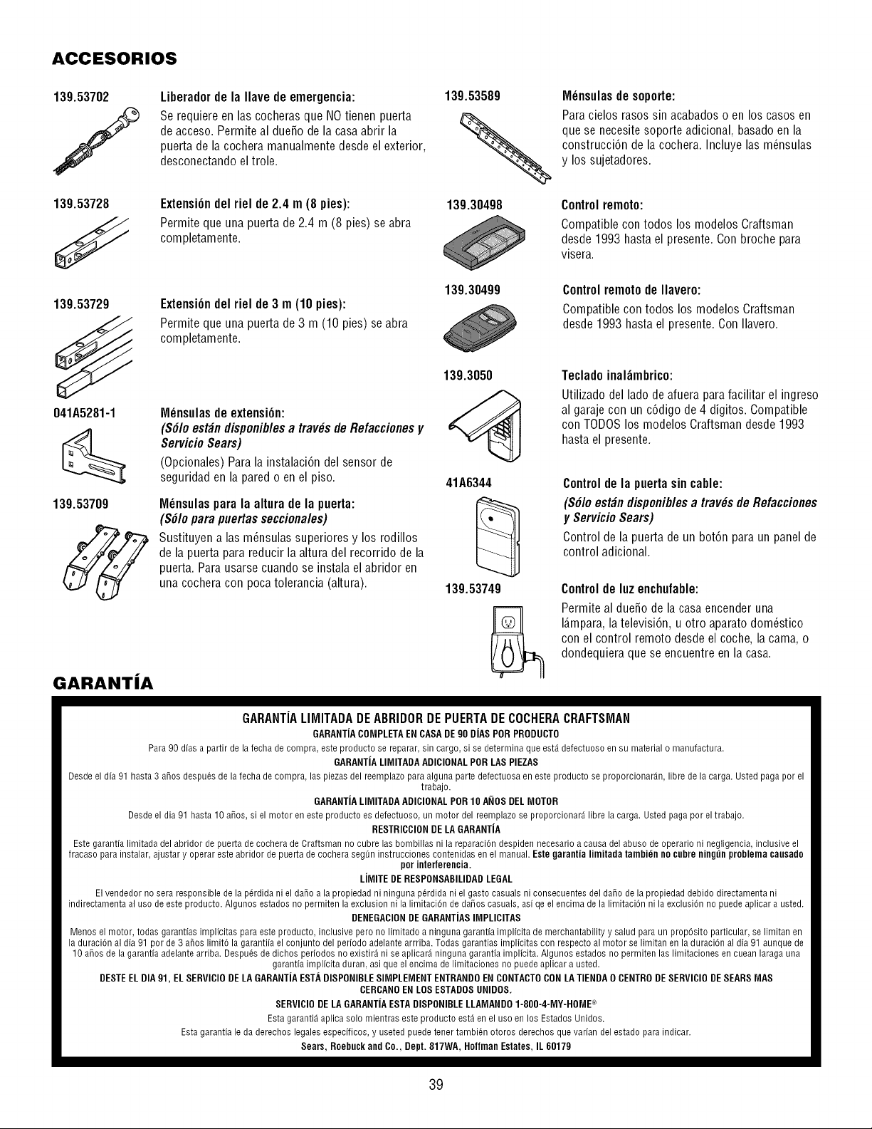
ACCESORIOS
139.53702
f
139.53728
Liberadorde la Ilave de emergencia:
Se requiere en las cocheras que NOtienen puerta
de acceso. Permite al due_o de la casaabrir la
puerta de la cochera manualmente desde el exterior,
desconectando el trole.
ExtensiOndel riel de 2.4 m (8 pies):
Permite que una puerta de 2.4 m (8 pies) se abra
completamente.
139.53589
139.30498
M_nsulas de soporte:
Para cielos rasos sin acabados o en los casos en
que se necesite soporte adicional, basadoen la
construcci6n de la cochera. Incluyelas m_nsulas
y los sujetadores.
Control remoto:
Compatible con todos los modelos Craftsman
desde 1993 hasta el presente. Con broche para
visera.
139.53729
ExtensiOndel riel de 3 m (10 pies):
Permite que una puerta de 3 m (10 pies) se abra
completamente.
139.30499 Control remotode Ilavero:
Compatible con todos los modelos Craftsman
desde 1993 hasta el presente. Con Ilavero.
041A5281-1
139.53709
GARANTJA
M_nsulasde extension:
(S#loest#ndisponiblesa tray,s deRefaccionesy
ServicioSears)
(Opcionales)Paralainstalaci6ndelsensorde
seguridadenlaparedo enelpiso.
M_nsulas para la altura de la puerta:
(S#lo para puertas seccionales)
Sustituyen alas m_nsulas superiores y los rodillos
de la puerta para reducir la altura del recorrido de la
puerta. Para usarse cuando se instala el abridor en
una cochera con poca tolerancia (altura).
139.3050
41A6344
139.53749
Teclado inal_mbrico:
Utilizado del ladode afuera para facilitar el ingreso
al garaje con un c6digo de 4 digitos. Compatible
con TODOSlos modelos Craftsman desde 1993
hasta el presente.
Controlde la puertasincable:
(S#Ioest#ndisponiblesa tray,s de Refacciones
y ServicioSears)
Controlde lapuertade un bot6nparaunpanelde
controladicional.
Controlde IGZenchufable:
Permite al dueSo de la casa encender una
I_.mpara,la televisi6n, u otro aparato dom_stico
con el control remoto desde el coche, la cam& o
dondequiera que se encuentre en la casa.
GARANTIALIMITADADEABRIDORDEPUERTADECOCHERACRAFTSMAN
GARANTiACOMPLETAENCASA DE90 DJASPOR PRODUCTO
Para 90 dias a partir de la techa de compra, este producto se reparar, sin cargo, si se determina que est4 defectuoso en su material o manufactura.
GARANTiALIMITADA ADIOIONALPOR LAS PIEZAS
Desdeel dia 91 hasta 3 ahos despu6s de la fecha de compra, las piezas del reemplazo para alguna parte defectuosa en este producto se proporcionar4n, libre de la carga. Usted paga por el
trabajo.
GARANTJALIMITADA ADICIONALPOR 10 ANOS DEL MOTOR
Desdeel dia 91 hasta 10 a_os, si el motor en este producto es defectuoso, un motor del reemplazo se proporcionar4 libre la carga. Usted paga por el trabajo.
RESTRICCIONDE LA GARANTiA
Este garantia limitada del abridor de puerta de cochera de Craftsnlan no cubre las bombillas ni la reparaci6n despiden necesario a causa del abuso de operario ni negligencia, inclusive el
fracaso para instalar, ajustar y operar este abridor de puerta de cochera segtin instrucciones contenidas en el manual. Esle garantia limitada tambidn no cubre ningtin problema causado
por interferencia.
LJMITE DERESPONSABILIDADLEGAL
Elvendedor no sera responsible de la pdrdida ni el da_o a la propiedad ni ninguna p6rdida ni el gasto casuals ni consecuentes del daho de la propiedad debido directamenta ni
indirectamenta al uso de este producto. Algunos estados no permiten la exclusion ni la limitaci6n de da5os casuals, asi qe el encima de la limitaci6n ni la exclusi6n no puede aplicar a usted.
DENEGACIONDE GARANTJASIMPLICITAS
Menos el motor, todas garantias implicitas para este producto, inclusive pero no limitado a ninguna garantia implicita de merchantability y salud para un prop6sito particular, se limitan en
la duraci6n al dia 91 por de 3 ahos limit6 la garantiia el conjunto del periodo adelante arrriba. Todas garantias implicitas con respecto al motor se limitan en la duraci6n al dia 91 aunque de
10 ahos de la garantia adelante arriba. Despu6s de dichos periodos no existir_ ni se aplicar4 ninguna garantia implicita. Algunos estados no permiten las limitaciones en cuean laraga una
garantia implicita duran, asi que el encima de limitaciones no puede aplicar a usted.
DESTEEL DIA 91, ELSERVICIO DE LA GARANTJAESTA DISPONIBLESIMPLEMENT ENTRANDOENCONTACTOCON LATIENDA 0 CENTRODESERVICIODE SEARSMAS
CERCANOEN LOS ESTADOSUNIDOS.
SERVICIO DELA GARANTiAESTA DISPONIBLELLAMANDO 1-800-4-MY-HOME ®
Esta garanti_ aplica solo mientras este producto est4 en el uso en los Estados Unidos.
Esta garantia le da derechos legales especificos, y useted puede tener tambi6n otoros derechos que varian del estado para indicar.
Sears, Roebuck and Co., Dept. 817WA, Holfman Estates, IL 60179
39

Your Home
For troubleshooting, product manuals and expert advice:
www.managemylife.com
For repair- in your home - of all major brand appliances,
lawn and garden equipment, or heating and cooling systems,
no matter who made it, no matter who sold it!
For the replacement parts, accessories and
owner's manuals that you need to do-it-yourself.
For Sears professional installation of home appliances
and items like garage door openers and water heaters.
1-800-4-MY-HOME ® (1-800-469-4663)
Call anytime, day or night (U.S.A. and Canada)
www.sears.com www.sears.ca
Our Home
For repair of carry-in items like vacuums, lawn equipment,
and electronics, call anytime for the location of your nearest
Sears Parts & Repair Service Center
1-800-488-1222 (U.S.A.) 1-800-469-4663 (Canada)
www.sears.com www.sears.ca
To purchase a protection agreement on a product serviced by Sears:
1-800-827-6655 (U.S.A.) 1-800-361-6665 (Canada)
Para pedir servicio de reparacidn
a domicilio, y para ordenar piezas:
1-888-SU-HOGAR ®
(1-888-784-6427)
Au Canada pour service en fran(_ais:
1-800-LE-FOYER Mc
(1-800-533-6937)
www.sears.ca
TM
® Registered Trademark / Trademark of KCD IP, LLC in the United States, or Sears Brands, LLC in other countries
® Marca Registrada / TMMarca de F_.brica de KCD IP, LLC en Estados Unidos, o Sears Brands, LLC in otros parses
MCMarque de commerce / MDMarque deposee de Sears Brands, LLC
114A4283F © 2013 KCP IP, LLC