Loading ...
Loading ...
Loading ...
YourCraftsmangeneratorrequiressomeassembly
andisreadyfor useonlyafterit hasbeenproperly
servicedwiththerecommendedoilandfuel.
Ifyou haveany problemswith theassemMyof
your generator,pleasecallthegeneratorhelpline
at 1-800-222-3136.
IMPORTANT:Anyattemptto runtheenginebeforeit
hasbeenservicedwiththerecommendedoilwillresult
inan enginefailure.
REMOVE GENERATOR FROM
CARTON
1. Set the carton on a rigid flat surface.
2. Remove everything from carton except generator.
3. Open carton completely by cutting each corner
from top to bottom.
4. Leave generator on carton to install wheel kit.
CARTON CONTENTS
Check all contents. If any parts are missing or damaged,
call the generator helpline at 1-800-222-3136.
• The main unit
• Owner's manual
• Engine oil
• 120/240 Volt, 30 Amp locking plug
• Wheel Kit
ASSEMBLING THE WHEEL KIT
NOTE: Wheel kit is not intended for over=the=road use.
You will need the following tools to install these
components:
• 1/2" or 13mm wrench
• Socket wrench with a 1/2" or 13mm socket
• Pliers
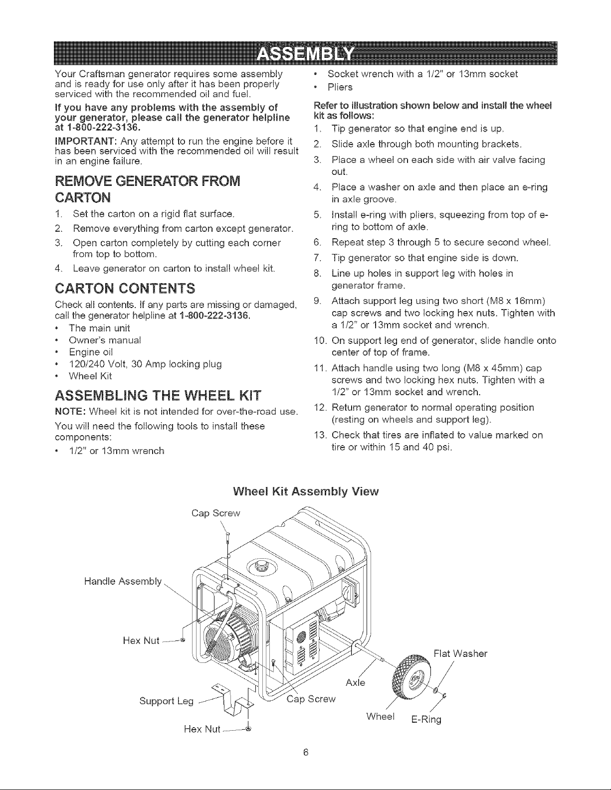
Refer to imlustrationshown below and install the wheel
kit as fol!ows:
1. Tip generator so that engine end is up.
2. Slide axle through both mounting brackets.
3. Place a wheel on each side with air valve facing
out.
4. Place a washer on axle and then place an e-ring
in axle groove.
5. Install e-dng with pliers, squeezing from top of e-
ring to bottom of axle.
6. Repeat step 3 through 5 to secure second wheel.
7. Tip generator so that engine side is down.
8. Line up holes in support leg with holes in
generator frame.
9. Attach support leg using two short (M8 x 16mm)
cap screws and two locking hex nuts. Tighten with
a 1/2" or 13mm socket and wrench.
10. On support leg end of generator, slide handle onto
center of top of frame.
11. Attach handle using two long (M8 x 45mm) cap
screws and two locking hex nuts. Tighten with a
1/2" or 13mm socket and wrench.
12. Return generator to normal operating position
(resting on wheels and support leg).
13. Check that tires are inflated to value marked on
tire or within 15 and 40 psi.
Whee_ Kit Assembly View
Cap Screw
\
\,
Handle Assembly,
Hex
Support Leg
Hex Nut _
Cap Screw
Axle
Wheel
Flat Washer
/
/
E=Ring
Loading ...
Loading ...
Loading ...