OWNER'S MANUAL
CAUTION
RISKOFELECTRICSHOCK
\ DONOTOPEN
CAUTION: TO REDUCE THE RISK OF
ELECTRIC SHOCK, DO NOT REMOVE
COVER (OR BACK). NO USER-SERVICEABLE
PARTS INSIDE. REFER SERVICING TO
QUALIFIED SERVICE PERSONNEL.
• Explanation of Graphical Symbols
The lighhling flash with alxowhead symbol within an
equilateral triangle, is intended to alert you to the
presence of unmsulated "dangerous voltage" within
the product's enclosure that may be of sufficient
magnitude to constitute a risk of elecnic shock to
persons
The exclamation point within an equilateral niangle
is intended to ale_ you to the presence of important
operating andmaintenance (servicing) instructions in
the literature accompanying the appliance
1 Read Instructions All the safety and operating instructions
should be read before the product is operated.
2 Retain Instructions The safety and operating instructions
should be retained for fnmre reference.
3 Heed Warnings All warnings on the product and in the
operating instructions should be adhered to.
4 Follow Instructions All operating and use instructions
should be followed.
5 Cleaning Unphtg this product from the wall outlet bel\_re
cleaning. Do not use liquid cleaners or aerosol cleaners. Use
a clean, dry cloth lbr cleaning.
6 Attachments Do not use attachments not recommended by
the product manui;actnrer as they may cause hazards.
7 \,_hter and Moisture Do not use this prodnct near water
for example, near a bath tnb. wash bowl, kitchen sink. or
laundry tub: in a wet basement: or near a swinnning pool:
and the like.
8 Accessories Do not place this product on an unstable cart,
stand, tripod, bracket, or table. The product may fall,
causing serious inju_" to a child or adulL and serious
damage to the product. Use only with a cart, stand, tripod,
bracket, or table reconmlended by the manui;actnrer, or sold
with the product Any mounting of the product should
follow the manui;acmrer's instructions, and should use a
mounting accesso_" recommended by the naanufacmrer.
9 A product and cart combination should be moved with care.
Quick stops, excessive force, and uneven
snrfaces may cause the prodnct and cart
combination to overturn
10 Ventilation Slots and openings in the cabinet are provided
for ventilation and to ensure reliable operation of the
product and to protect it from overheating, and these
openings must not be blocked or covered. The openings
should never be blocked by placing the product on a bed,
sol;a, rug, or other similar surface. This product should not
be placed in a built-in installation such as a bookcase or rack
unless proper ventilation is provided or the manufacturer's
instructions have been adhered to.
11 Power Sources This product should be operated only from
the type of power soarce indicated on the marking label. If
you are not sure of the type of power supply to your home.
consult your product dealer or local power compan)t For
products intended to operate from batte D"power, or other
sources, refer to the operating instructions.
12 Grounding or Polarization This product may be equipped
with a polarized altemating current line plug (a plug having
one blade wider than the other). This plug will fit into the
power ontlet only one way. This is a safety feature. If you
are unable to insert the plug fully into the outlet, tD"
reversing the plug. If the plug should still fail to fit, contact
your electrician to replace your obsolete outlet. Do not
defeat the safety purpose of the polarized plug.
13 Power-Cord Protection Power-supply cords should be
romed so that they are not likely to be walked on or pinched
by items placed npon or against them, paying particular
attention to cords at plugs, convenience receptacles, and the
point where they exit from the product.
14 Lightning For added protection for this product during a
lightning storm, or when it is left unattended and unused for
long periods of time. unphtg it from the wall omlet and
disconnect the antenna or cable system. This will prevent
damage to the product due to lightning and power-line
surges.
15 Power Lines An omside antemla system should not be
located in the vicinity of overhead power lines or other
electric light or power circuits, or where it can l;all into such
power lines or circuits. When installing an omside antenna
system, extreme care should be taken to keep from touching
such power lines or circuits as contact with them might be
fatal.
16 Overloading Do not overload wall outlets, extension
cords, or integral convenience receptacles as this can result
in a risk of fire or electric shock.
17 Object and Liquid Entry Never push o[!iects of any kind
into this product through openings as they may touch
dangerous voltage points or short-out parts that could result
in a fire or electric shock. Never spill liquid of any kind on
the product.
18 Servicing Do not attempt to service this product yonrself
as opening or removing covers may expose you to
dangerous voltage or other hazards. Refer all servicing to
qualified service persoanel.
19 Damage Requiring Service Unplug this product from the
wall outlet and refer servicing to qualified sendce personnel
under the following conditions:
a) \t]len the power-supply cord or plug is damaged,
b) If liquid has been spilled, or objects have ihllen into the
product,
c) If the product has been exposed to rain or water.
20
d) If the product does not operate normally by %llowing
the operating instructions. Adiust only those controls
that are covered by the operating instructions as an
improper adiustment of other controls may result in
damage and will often require extensive work by a
qnalified teclmician to restore the product to its normal
operation,
e) If the product has been dropped or damaged in any
wa3\ and
t) When the prodnct exhibits a distinct change in perfor-
mance - this indicates a need for service.
Replacement Parts \_&en replacement parts are reqnired,
be sure the service technician has used replacement parts
specified by the manufacturer or have the same
characteristics as the original part. Unauthorized
substitutions may result in fire, electric shock, or other
hazards.
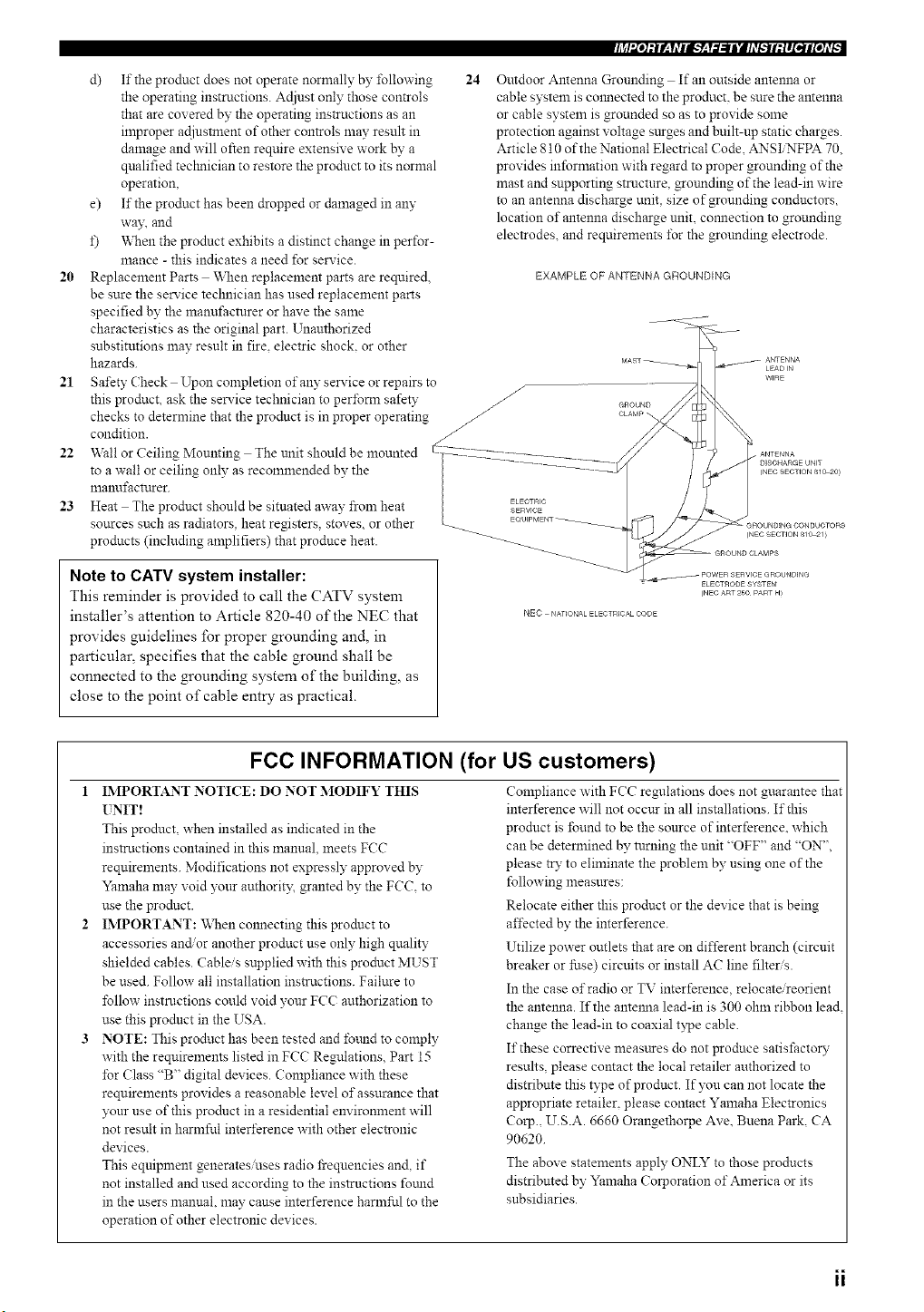
24
Outdoor Antenna Grounding If an outside antenna or
cable system is colmected to the product, be sure the antenna
or cable system is grounded so as to provide some
protection against voltage sttrges and built-up static charges.
Article 810 of the National Electrical Code, ANSIiNFPA 70.
provides information with regard to proper grounding of the
mast and supporting stmctnre, _otmding of the lead-in wire
to an antenna discharge unit, size of grounding conductors,
location of antenna discharge unit, comlection to grounding
electrodes, and requirements tbr the grmmding electrode.
EXAMPLE OF ANTENNA GROUNDING
21 Safety Check Upon completion of any serxice or repairs to
/
this product, ask the service technician to perfom_ safety _ cnouND
checks to determine that the product is in proper operating _ CLA_'.
condition. _ ........
22 Wall or Ceiling Mounting The unit should be mounted -I27_2222_-_2222__T222Z.................... __
to a wall or ceiling only as recommended by the ................ 5/
manufactrtrer. |
23 Heat The product should be sitnated away from heat _cT)c /
sources such as radiators, heat registers, stox es. or other _ EOU_PMENT_
products (including amplifiers) that produce heat. _ _
Note to CATV system installer:
This reminder is provided to call the CATV system
installer's attention to Article 820-40 of the NEC that NEC ._,o,_o_,o_,o_
provides guidelines for proper grounding and, in
particular, specifies that the cable ground shall be
connected to the grounding system of the building, as
close to the point of cable entry as practical.
FCC INFORMATION (for US customers)
1 IMPORTANT NOTI(?E: DO NOT MODIFY THIS
UNIT!
This product, when installed as indicated in the
instructions contained in this manual, meets FCC
requirements. Modifications not expressly approved by
Yamaha may void yonr authorit3; granted by the FCC. to
use the prodnct.
IMPORTANT: When cmmecting this prodnct to
accessories and/or another product use only high qnality
shielded cables. Cableis supplied with this product MUST
be used. Follow all installation ins_uctions. Failure to
follow instructions could void your FCC authorization to
use this product in the USA.
NOTE: This prodnct has been tested and fomld to comply
with the requirements listed in FCC Regulations. Part 15
for (?lass "B" digital devices. Compliance with these
requirements provides a reasonable level of assurance that
yonr use of this prodnct in a residential environment will
not result in harmful interference with other electronic
devices.
This equipment generates uses radio _equencies and, if
not installed and used according to the instructions fotmd
in the users manual, may cause interference harmful to the
operation of other electronic devices.
Compliance with FCC regulations does not guarantee that
interference will not occur in all installations. If this
product is found to be the source of interference, which
can be determined by turning the unit "OFF" and "ON",
please try to eliminate the problem by using one of the
following measnres:
Relocate either this product or the device that is being
affected by the interference.
Utilize power outlets that are on different branch (circuit
breaker or fuse) circuits or install AC line filters.
In the case or'radio or TV interference,relocate/reorient
the antenna. If the antelma lead-in is 300 ohm ribbon lead
change the lead-in to coaxial type cable.
It"these corrective measares do not produce satisfactoW
results, please contact the local retailer authorized to
distribute this type of product. If you can not locate the
appropriate retailer, please contact Yamaha Electronics
Corp., U.S.A. 6660 Orangethorpe Ave. Buena Park, CA
90620.
The above statements apply ONLYto those products
distributed by Yamaha Corporation of America or its
subsidiaries.
ii
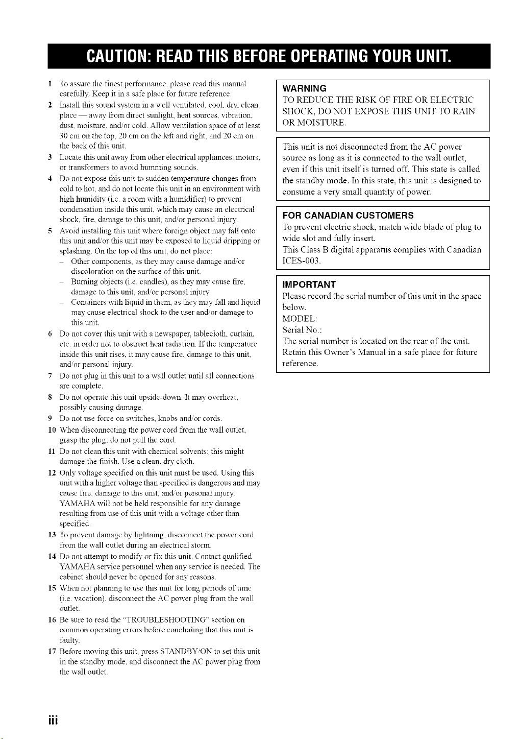
1 To assure the finest perfomlance, please read this manual
carefnll?: Keep it in a safe place for future reference.
2 Install this sound system in a well ventilated, cool, d_'. clean
place away fi'om direct sunlight, heat sottrces, vibration,
dust, moisture, an_or cold. Allow ventilation space of at least
30 cm on the top, 20 cm on the left and right, and 20 cm on
the back of this unit.
3 Locate this unit away from other electrical appliances, motors.
or transl\_rmers to avoid hunmaing sounds.
4 Do not expose this unit to sudden temperature changes from
cold to hot, and do not locate this unit in an environment with
high humidity (i.e. a room with a hmnidifier) to prevent
condensation inside this unit. which may cause an electrical
shock, fire, damage to this unit, anct or personal injury.
5 Avoid installing this unit where foreign object may fall onto
this unit and'or this unit may be exposed to liquid dripping or
splashing. On the top of this unit. do not place:
Other components, as they may cause damage andor
discoloration on the surl'ace of this unit.
Bttrning olziects (i.e. candles), as they may cause fre,
dan_age to this unit, and/or personal iNuD'.
Containers with liquid in them, as they may l'all and liquid
may cause electrical shock to the user andor damage to
this trait.
6 Do not cover this unit with a newspapec tablecloth, curtain.
etc. in order not to obstrnct heat radiation. If the temperature
inside this unit rises, it may cause fire. damage to this unit,
and/or personal il:.iury.
7 Do not plug in this unit to a wall outlet nntil all connections
are complete.
8 Do not operate this unit upside-down. It may overheat,
possibly causing damage.
9 Do not use force on switches, knobs andor cords.
10 When discomlecting the power cord from the wall omlet,
grasp the plug; do not pull the cord.
11 Do not clean this unit with chemical solvents: this might
danaage the finish. Use a clean, dry cloth.
12 Only voltage specified on this tmit nmst be used. Using this
unit with a higher voltage than specified is dangerous and may
cause fire, damage to this unit, and/or personal iNury.
YAMAHA will not be held responsible for an?"damage
resulting from use of this tulit with a voltage other than
specified.
13 To prevent damage by lightning, discomlect the power cord
from the wall outlet during an electrical stom_.
14 Do not attempt to modil_" or fix this unit. Contact qualified
YAMAHA service personnel when an?"service is needed. The
cabinet should never be opened for an?" reasons.
15 When not planning to use this unit for long periods of time
(i.e. vacation), discoanect the AC power plug fi'om the wall
outlet.
16 Be snre to read the "TROUBLESHOOTING" section on
connnon operating errors before concluding that this nnit is
lhults:
17 Before moving this unit, press STANDB_ON to set this unit
in the standby mode, and disconnect the AC power plug fi'om
the wall outlet.
WARNING
TO REDUCE THE RISK OF FIRE OR ELECTRIC
SHOCK, DO NOT EXPOSE THIS L_'IT TO RAIN
OR MOISTURE.
This unit is not disconnected fi'om the AC power
source as long as it is connected to the wall outlet,
even if this unit itself is turned off. This state is called
the standby mode. In this state, this unit is designed to
consume a very small quantity of power.
FOR CANADIAN CUSTOMERS
To prevent electric shock, match wide blade of plug to
wide slot and fully insert.
This (:lass B digital apparatus complies with Canadian
ICES-003.
IMPORTANT
Please record the serial number of this unit in the space
below.
MODEL:
Serial No.:
The serial number is located on the rear of the unit.
Retain this Owner's Manual in a safe place for future
reference.
===
III
"OD Q
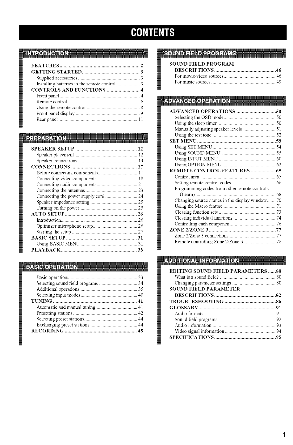
FEAT[ RES ............................................................. 2
GETTING STARTED ............................................ 3
Supplied accessories .................................................. 3
Installing batteries in the remote con_ol ................... 3
CONTROLS AND FUNCTIONS ......................... 4
Front panel ................................................................. 4
Remote control ........................................................... 6
Using the remote con_ol ........................................... 8
Front panel display .................................................... 9
Rear panel ................................................................ 11
SPEAKER SETUP ............................................... 12
Speaker placement ................................................... 12
Speaker colmections ................................................ 13
CONNECTIONS .................................................. 17
Before connecting components ................................ 17
Connecting video components ................................. 18
Connecting audio components ................................. 21
Connecting the antennas .......................................... 23
Connecting the power supply cord .......................... 24
Speaker impedance setting ...................................... 25
Tttrning on the power ............................................... 25
AUTO SETUP ....................................................... 26
In_oduction .............................................................. 26
Optimizer microphone setup .................................... 26
Starting the setup ..................................................... 27
BASIC SETUP ...................................................... 31
Using BASIC ME_",qr .............................................. 31
PLAYBACK .......................................................... 33
Basic operations ....................................................... 33
Selecting sound field programs ............................... 34
Additional operations ............................................... 35
Selecting input modes .............................................. 40
T[ NING ................................................................ 41
Automatic and manual tuning .................................. 41
Presetting stations .................................................... 42
Selecting preset stations ........................................... 44
Exchanging preset stations ...................................... 44
RECORDING ....................................................... 4g
SOIND FIELD PROGRAM
DESCRIPTIONS ............................................... 46
For movi#video sources .......................................... 46
For music sources .................................................... 49
!
ADVANCED OPERATIONS .............................. 50
Selecting the OSD mode .......................................... 50
Using the sleep timer ............................................... 50
Mannally adjusting speaker levels ........................... 51
Using the test tone ................................................... 52
SET MENU ............................................................ 53
Using SET MENU ................................................... 54
Using SOLrND MENU ............................................ 55
Using INPUT MENU .............................................. 60
Using OPTION MENU ........................................... 62
REMOTE CONTROL FEATURES ................... 65
Control area ............................................................. 65
Setting remote control codes ................................... 66
Progranmling codes from other remote controls
(Learn) ................................................................. 68
Changing soarce names in the display window ....... 70
Using the Macro feature .......................................... 71
Clearing function sets .............................................. 73
Clearing individual functions .................................. 74
Controlling each component .................................... 76
ZONE 2/ZONE 3 ................................................... 77
Zone 2/Zone 3 connections ...................................... 77
Remote controlling Zone 2/Zone 3 .......................... 78
11
EDITING SOUND FIELD PARAMETERS ...... 80
\_mt is a sound field'? ............................................. 80
Changing parameter settings ................................... 80
SOIND FIELD PARAMETER
DESCRIPTIONS ............................................... 82
TROUBLESHOOTING ....................................... 86
GLOSSARY ........................................................... 91
Andio formats .......................................................... 91
Sound field programs ............................................... 92
Andio in±bmaation ................................................... 93
Video signal infomaation ......................................... 94
SPECIFICATIONS ............................................... 95
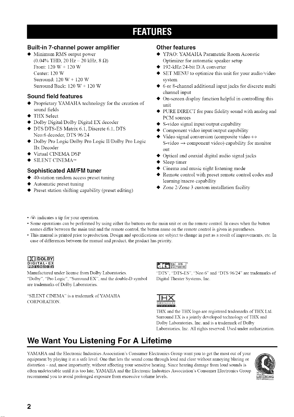
Built-in 7-channel power amplifier
Minimum RMS output power
(0.04% THD, 20 Hz 20 kHz, 8 £2)
Front: 120 W + 120 W
Center: 120 W
Surround: 120 W + 120 W
Surround Back: 120 W + 120 W
Sound field features
I_ Proprietary YAMAHA technology for the creation of
sound fields
THX Select
Dolby DigitaliDolby Digital EX decoder
I_ DTSiDTS-ES Matrix 6.1, Discrete 6.1, DTS
Neo:6 decoder, DTS 96/24
I_ Dolby Pro LogiciDolby Pro Logic IIiDolby Pro Logic
IIx Decoder
Virtual CINEMA DSP
SILENT CINEMA TM
Sophisticated AM/FM tuner
I_ 40-station random access preset tuning
I_ Automatic preset tuning
Preset station shifting capability (preset editing)
Other features
YPAO: YAMAHA Parametric Room Acoustic
Optimizer for automatic speaker setup
I_ 192-kHzi24-bit DiA converter
I_ SET MENU to optimize this unit for your audio'video
system
I_ 6 or 8-channel additional input jacks for discrete multi
channel input
I_ On-screen display function helpful in controlling this
unit
I_ PURE DIRECT for pure fidelity sound with analog and
PCM sources
I_ S-video signal input/output capability
I_ Component video input/output capability
I_ Video signal conversion (composite video <-+
S-video --> component video) capability for monitor
out
I_ Optical and coaxial digital audio signal jacks
I_ Sleep timer
I_ Cinema and music night listening mode
I_ Remote control with preset remote control codes and
learning macro capability
I_ Zone 2/Zone 3 custom installation facility
• -"4;'-indicates a tip for your operation.
• Some operations can be performed by using either the buttons on the main unit or on the remote control. In cases when the bntton
nanaes differ between the main unit and the remote control, the button name on the remote control is given in parentheses.
• This manual is printed prior to production. Design and specifications are subject to change in part as a result of improvements, etc. In
case of differences between the manual and product, the product has priority.
[1rt_
DIGITAL _ lt_N
Manufactured trader license from Dolby Laboratories.
"Dolby", "Pro Logic", "Sttrround EX". and the double-D symbol
are trademarks of Dolby Laboratories.
"DTS". "DTS-ES", "Neo:6" and "DTS 9624" are trademarks of
Digital Theater Systems. Inc.
"SILENT CINEMA" is a trademark of YAMAHA
CORPORATION.
SURROUND EX
lilllllHlllllXlt.
THX and the THX logo are registered trademarks of THX Ltd.
Surround EX is a jointly dex eloped technology of THX and
Dolby Laboratories. Inc. and is a trademark of Dolby
Laboratories. Inc. All rights reserved. Used under authorization.
We Want You Listening For A Lifetime
YAMAHA and the Electronic Industries Association's Consumer Electronics Gronp want you to get the most out of yonr
equipment by playing it at a safe level. One that lets the sound come tl_rongh loud and clear without annoying blaring or
distortion and, most importantl?; without affecting your sensitive hearing. Since hearing damage from loud sounds is
often undetectable until it is too late, YAMAHA and the Electronic Indnstries Association's Consnmer Electronics Group
recommend yon to avoid prolonged exposnre froln excessive vohnne levels.
LISTZNING
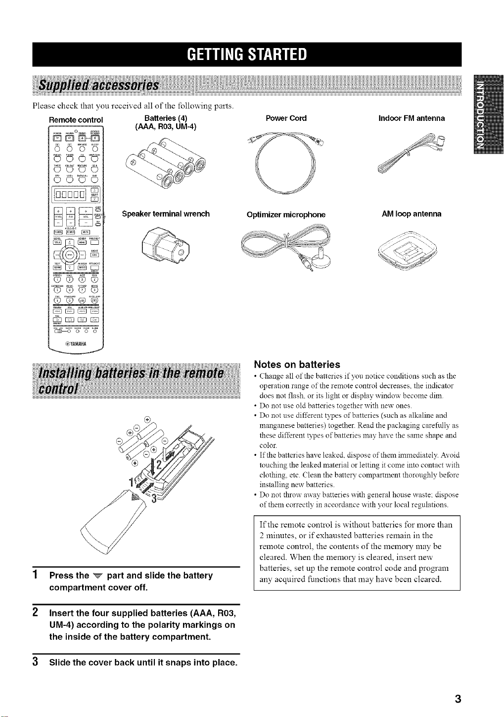
Please check that you received all of the following parts.
Remote control
CD _D 0 0
© ©°_©
9©,
OOQO
OOQQ
F2 C:2}{:--=-:3
@_MAH_
Batteries (4)
(AAA, R03, UM-4)
Speaker terminal wrench
Press the _ part and slide the battery
compartment cover off.
Insert the four supplied batteries (AAA, R03,
UM-4) according to the polarity markings on
the inside of the battery compartment.
3 Slide the cover back until it snaps into place.
Power Cord Indoor FM antenna
Optimizer microphone
AM loop antenna
Notes on batteries
• Change all of the batteries if )_u notice conditions such as the
operation range of the remote control decreases, the indicator
does not flash, or its light or display window become dim.
• Do not use old batteries together with new ones.
• Do not use different types of batteries (such as alkaline and
manganese batteries) together. Read the packaging careftdly as
these different types of batteries may have the same shape and
color.
• If the batteries have leake& dispose of them immediately. AYoid
touching the leaked material or letting it come into contact with
clothing, etc. (}lean the battery compartment thoroughly before
installing new batteries.
• Do not throw away batteries with general house waste: dispose
of them correctly in accordance with your local regulations.
If the remote control is without batteries for more than
2 minutes, or if exhausted batteries remain in the
remote control, the contents of the memory may be
cleared. When the memory is cleared, insert new
batteries, set up the remote control code and program
any acquired functions that may have been cleared.
3
..........._3
J
o
@ @ @ @
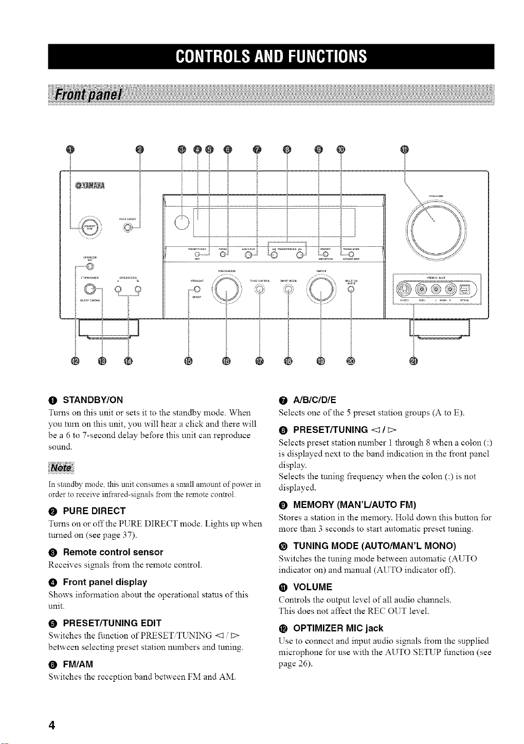
O STANDBY/ON
Turns on this unit or sets it to the standby mode. When
you tum on this unit, you will hear a click and there will
be a 6 to 7-second delay before this unit can reproduce
sol.lnd.
NoZe
In standby mode. this mlit consmnes a small amount of power in
order to receive infrared-signals from the remote control.
O PURE DIRECT
Turns on o1"off the PURE DIRECT mode. Lights up when
turned on (see page 37).
O Remote control sensor
Receives signals ficom the remote control.
0 Front panel display
Shows information about the operational status of this
unit.
O PRESET/TUNING EDIT
Switches the function of PRESET T[_ING <1 [::>
between selecting preset station numbers and tuning.
0 FM/AM
Switches the reception band between FM and AM.
0 A/BICIDIE
Selects one of the 5 preset station groups (A to E).
O PRESET/TUNING <1 / c>
Selects preset station number 1 through 8 when a colon (:)
is displayed next to the band indication in the front panel
display.
Selects the tuning frequency when the colon (:) is not
displayed.
O MEMORY (MAR'L/AUTO FM)
Stores a station in the memory. Hold down this button for
more than 3 seconds to start automatic preset tuning.
@ TUNING MODE (AUTO/MAN'L MONO)
Switches the tuning mode between automatic (AUTO
indicator on) and manual (AUTO indicator ofI).
O VOLUME
Controls the output level of all audio channels.
This does not affect the REC OUT level.
_) OPTIMIZER MIC jack
Use to connect and input audio signals l'rom the supplied
microphone for use with the AUTO SETUP function (see
page 26).
4
@ (_ PHONES (SILENT CINEMA) jack
Outputs audio signals for listening with headphones.
When you connect headphones, no signals are output to
the PRE OUT jacks or to the speakers.
All Dolby Digital and DTS audio signals are mixed down
to the left and right headphone channels.
O SPEAKERS A/B
Turn on or off the set of front speakers connected to the A
and/or B terminals on the rear panel each time the
corresponding button is pressed.
O STRAIGHT/EFFECT
Switches the sound fields off or on. When STRAIGHT is
selected, input signals (2-channel or multi-channel) are
output directly from their respective speakers without
effect processing.
@ PROGRAM
Use to select sound field programs or adjust bass treble
balance (in conjunction with TONE CONTROL).
• TONE CONTROL
Use to adjust the bass treble balance for the front left right
and center channels (see page 35).
O INPUT MODE
Sets the priority (AUTO, DTS, ANALOG) for the type of
signals received when one component is connected to two
or more of this unit's input jacks (see page 40).
_) INPUT selector
Selects the input source you want to listen to or watch.
@ MULTI CH INPUT
Selects the source connected to the MULTI CH INPUT
jacks. When selected, the MULTI CH INPUT source takes
priority over the source selected with INPUT (or the input
selector buttons on the remote control).
_) VIDEO AUX jacks
Input audio and video signals from an extemal source
such as a game console. To reproduce source signals from
these jacks, select V-AUX as the input source.
_e]dll:{e]l_l'_,Idl_l_lld[e,_#[eld$
5
|O[O]_TII:{O]i_.'I_q_TIII:IhT[m'*II[O]_T_
This section describes the function of each control on the
remote control used to control this unit. To operate other
components, see "REMOTE CONTROL FEATURES" on
page 65.
@
I
.....
D
88
V-AUX CBIJS,_T MD,TAPE CD-R
......O (D O (D
DDDDD
C23
--_ PtESE r " AMP
+ + +
-- $0URC
TVVOL CH VOL
J
_ _ _ TV
cTqcB CTq
DISCstop
@YAMAHA
@
--@
=@
=@
--@
@
@
--@
@
@
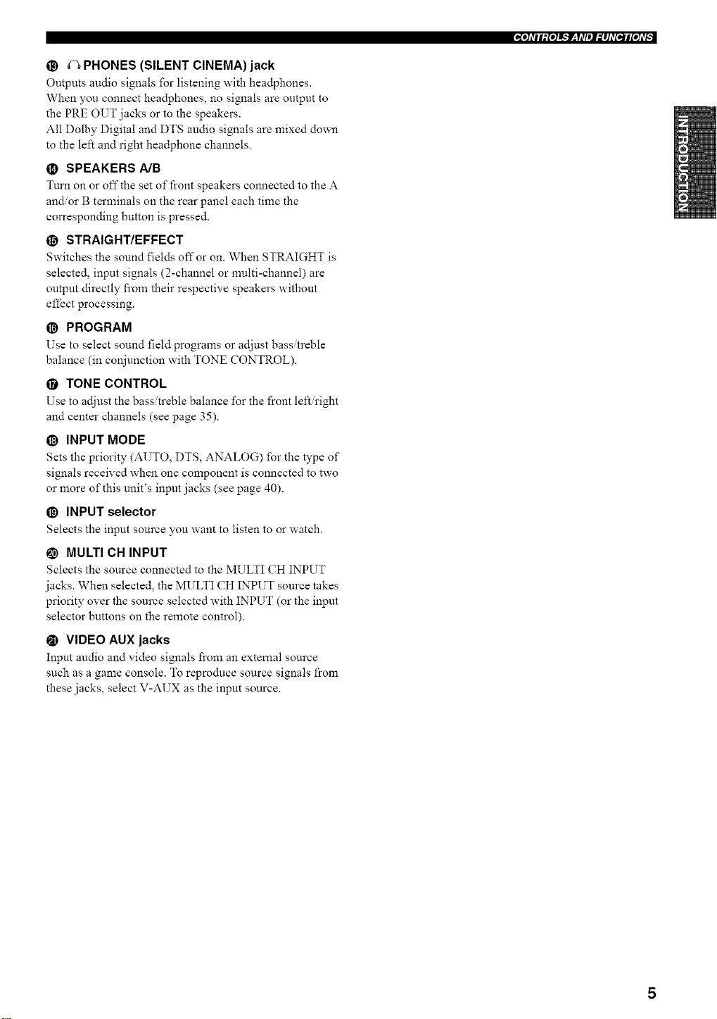
O Infrared window
Outputs infrared control signals. Aim this window at the
component you want to operate.
O Transmission indicator
Flashes while the remote control is sending signals.
O Input selector buttons
Select the input source and change the control area.
O Display window
Shows the name of the selected source component that
you can control.
O PRESET +/-
Selects preset station numbers when this unit is in tuner
mode.
0 A/BICIDIE
Selects preset groups when this unit is in tuner mode.
O LEVEL
Selects the speaker channel to be adjusted and sets the
level.
O Cursor buttons/_ / V / <1 / C>/ ENTER
Use to select and adjust DSP program parameters or SET
MENU items.
O TEST
Outputs the test tone to adjust the speaker levels.
@ Sound field program/Numeric buttons
Use to select sound l_eld programs or input numbers.
Use numbers 1 through 8 to select preset stations when
this unit is in tuner mode.
O MACRO ON/OFF
Turns the macro function on and ofI_
O MACRO
Use to program a series of operations for control by a
single button (see page 71).
@ STANDBY
Sets this unit in the standby mode.
_) SYSTEM POWER
Turns on the power of this unit.
O INPUT MODE
Sets the priority (AUTO, DTS, ANALOG) for the type of
signals received when one component is connected to two
or more of this unit's input jacks (see page 40).
@ SLEEP
Sets the sleep timer.
• MULTI CH IN
Selects MULTI CH INPUT when using an external
decoder (etc.).
6
@ SELECT A/?
Selects another component that you can control
independently of the input component selected with the
input selector buttons.
@ VOL +/-
Increases o1"decreases the volume leveh
@ AMP/SOURCE/TV
Selects the component you want to control with the
remote control.
AMP: Set to this position to operate this unit.
SOURCE: Set to this position to operate the component
selected with an input selector button.
TV: Set to this position to operate the television.
To set the remote control codes lbr components, see
page 66.
@ MUTE
Mutes the sound. Press again to restore the audio output to
the previous volume level. You can adjust how much the
mute function reduces the output volume in the MUTE
menu of the SET MENU mode (see page 59).
• PURE DIRECT
Turns on or off PURE DIRECT mode (see page 37).
@ SET MENU
Selects the SET MENU mode.
NIGHT
Turns on or off the night listening modes (see page 38).
O ON SCREEN
Selects the display mode of the on-screen display (OSD)
this unit sends to your monitor.
!_ STRAIGHT/EFFECT
Switches the sound fields off or on. When STRAIGHT is
selected, input signals (2-channel or multi-channel) are
output directly from their respective speakers without
effect processing.
• EXTD. SUR
Switches between 5. l or 6.1 7.1 channel playback of
nmlti-ehannel software.
RE-NAME
Used to change the input source name in the display
window (see page 70).
_) CLEAR
Used to clem" functions acquired when using the learn and
rename features, or setting remote control codes (see
page 73).
@ LEARN
Used to set up the remote control code or program
functions from other remote controls (see pages 66 and
68).
,,IO]dll:{o]l_*tT__Ydl_l_#ld[e,*l#[old_
7
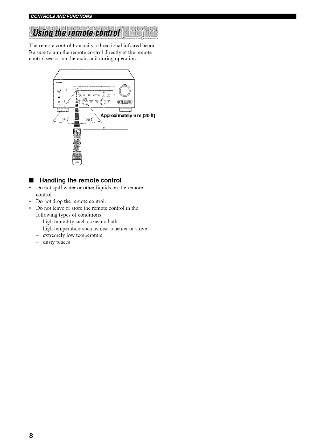
The remote control transmits a directional infrared beam.
Be sure to aim the remote control directly at the remote
control sensor on the main unit during operation.
Approximately6 m (20 It)
Handling the remote control
Do not spill water 02"other liquids on the remote
control.
Do not drop the remote control.
Do not leave or store the remote control in the
following types of conditions:
high humidity such as near a bath
high temperature such as near a heater or stove
extremely low temperature
dusty places
8
"[I]_TII:{I]!',.'lr-_y_T/II,_I]AT[tlI[I]_T[
V-AUX MD/TAPE CD-R CD
SILENT YPAO AUTO STEREO
_HiFi DSP
MEMORY TUNED
I CINEMA
@
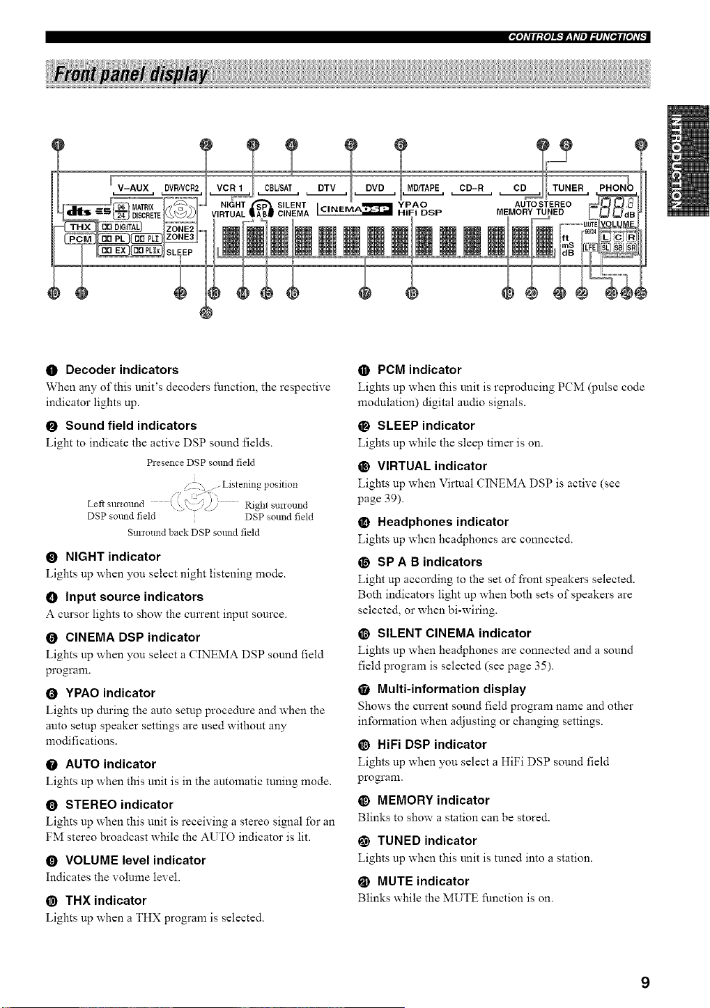
O Decoder indicators
When any of this unit's decoders function, the respective
indicator lights up.
O Sound field indicators
Light to indicate the active DSP sound fields.
Presence DSP solmd field
. Z . Listening position
Left Sll!-iollnd ' S i
. \ .q// I_ght st no1 nd
DSP sound field DSP sound field
Surround back DSP sound field
O NIGHT indicator
Lights up when you select night listening mode.
O Input source indicators
A cursor lights to show the current input source.
O CINEMA DSP indicator
Lights up when you select a CINEMA DSP sound field
program.
O YPAO indicator
Lights up during the auto setup procedure and when the
auto setup speaker settings are used without any
modifications.
O AUTO indicator
Lights up when this unit is in the automatic tuning mode.
O STEREO indicator
Lights up when this unit is receiving a stereo signal for an
FM stereo broadcast while the AUTO indicator is lit.
O VOLUME level indicator
Indicates the volume level.
@ THX indicator
Lights up when a THX program is selected.
O PCM indicator
Lights up when this unit is reproducing PCM (pulse code
modulation) digital audio signals.
O SLEEP indicator
Lights up while the sleep timer is on.
@ VIRTUAL indicator
Lights up when Virtual CINEMA DSP is active (see
page 39).
_) Headphones indicator
Lights up when headphones are connected.
O SP A B indicators
Light up according to the set of front speakers selected.
Both indicators light up when both sets of speakers are
selected, or when bi-wiring.
@ SILENT CINEMA indicator
Lights up when headphones are connected and a sound
field program is selected (see page 35).
• Multi-information display
Shows the cun'ent sound field program name and other
information when adjusting or changing settings.
O HiFi DSP indicator
Lights up when you select a HiFi DSP sound field
progranL
_) MEMORY indicator
Blinks to show a station can be stored.
@ TUNED indicator
Lights up when this unit is tuned into a station.
@ MUTE indicator
Blinks while the MUTE function is on.
9
EoI, Idl/l:{,ll_._-q_Jl_lld[_l[,Id[,:
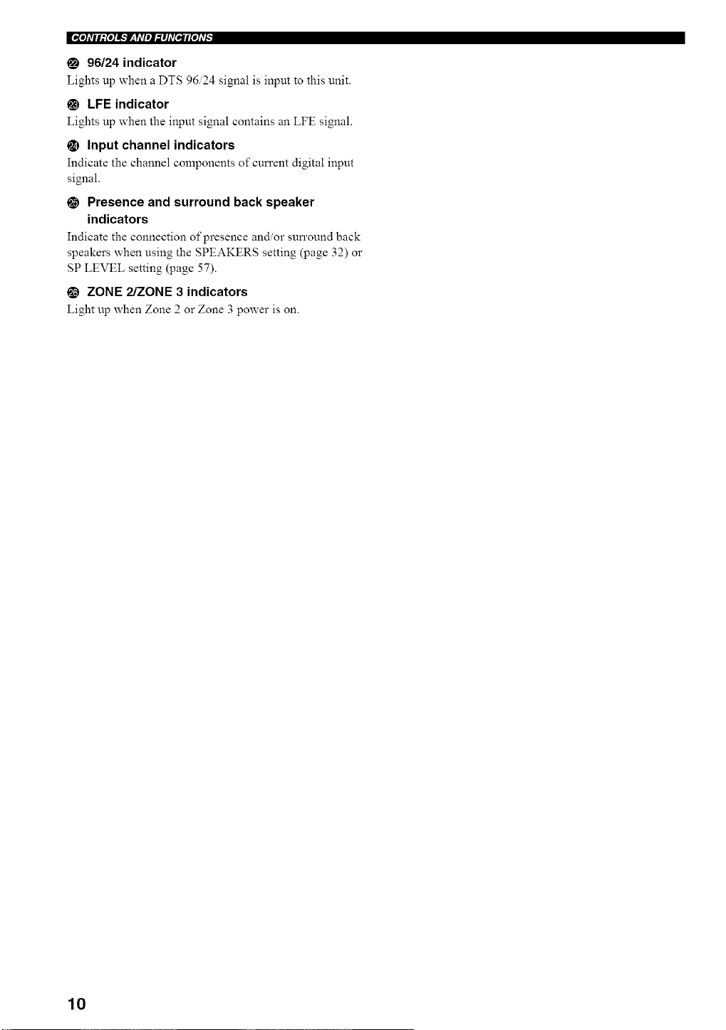
96/24 indicator
Lights up when a DTS 96/24 signal is input to this unit.
@ LFE indicator
Lights up when the input signal contains an LFE signal.
_) Input channel indicators
Indicate the channel components of cun'ent digital input
signal.
0 Presence and surround back speaker
indicators
Indicate the connection of presence andor sun'ound back
speakers when using the SPEAKERS setting (page 32) or
SP LEVEL setting (page 57).
_) ZONE 2/ZONE 3 indicators
Light up when Zone 2 or Zone 3 power is on.
10
"[I]_TII:{I]!',.'lr-_y_TIII,_I]AT[tlI[I]_T[
÷
/i
@
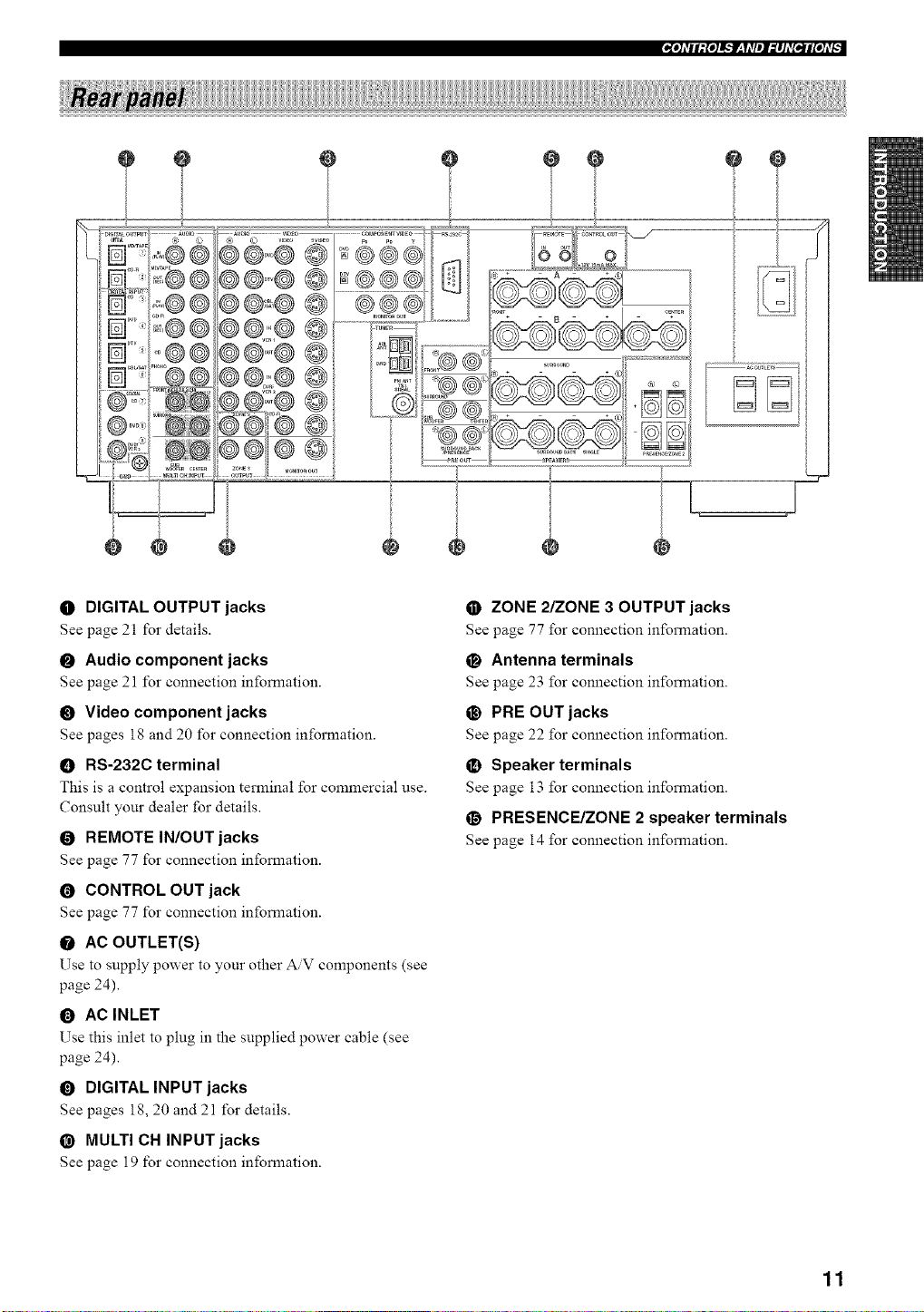
O DIGITAL OUTPUT jacks
See page 21 for details.
O Audio component jacks
See page 21 for connection information.
O Video component jacks
See pages 18 and 20 for connection information.
O RS-232C terminal
This is a control expansion terminal for commercial use.
Consult your dealer for details.
O REMOTE IN/OUT jacks
See page 77 for connection information.
O CONTROL OUT jack
See page 77 for connection information.
O AC OUTLET(S)
Use to supply power to your other AV components (see
page 24).
0 AC INLET
Use this inlet to plug in the supplied power cable (see
page 24).
O DIGITAL INPUT jacks
See pages 18, 20 and 21 for details.
@ MULTI CN INPUT jacks
See page 19 for connection information.
• ZONE 2/ZONE 3 OUTPUT jacks
See page 77 for connection information.
O Antenna terminals
See page 23 for connection information.
@ PRE OUT jacks
See page 22 for connection information.
_) Speaker terminals
See page 13 for connection information.
O PRESENCE/ZONE 2 speaker terminals
See page 14 for connection information.
11
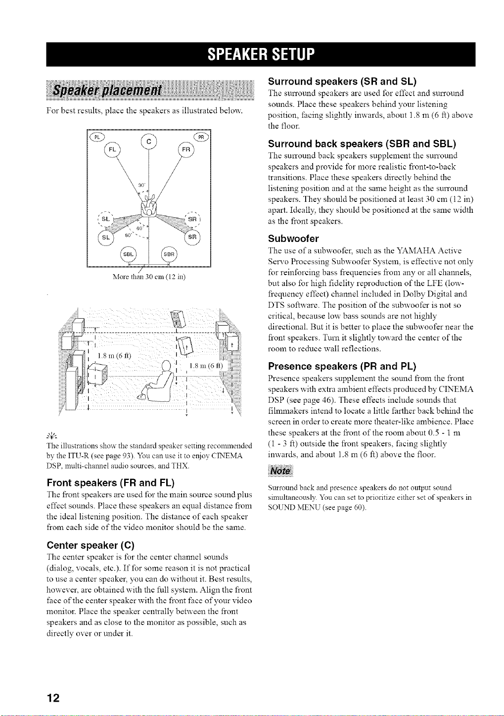
For best results, place the speakers as illustrated below.
(£9
\ 30
More than 30 Clll (12 in)
The illustrations show the standard speaker setting recommended
by the ITU-R (see page 93). You can use it to el_ioy CINEMA
DSP, umlti-channel audio sources, and THX.
Front speakers (FR and FL)
The front speakers are used for the main source sound plus
effect sounds. Place these speakers an equal distance fi'om
the ideal listening position. The distance of each speaker
from each side of the video monitor should be the same.
Center speaker (C)
The center speaker is for the center channel sounds
(dialog, vocals, etc.). If for some reason it is not practical
to use a center speaker, you can do without it. Best results,
however, are obtained with the full system. Align the front
fiace of the center speaker with the front face of your video
monitor. Place the speaker centrally between the front
speakers and as close to the monitor as possible, such as
directly over or under it.
Surround speakers (SR and SL)
The sun'ound speakers are used for effect and sun'ound
sounds. Place these speakers behind your listening
position, _acing slightly inwards, about 1.8 an (6 ft) above
the floor.
Surround back speakers (SBR and SBL)
The surronnd back speakers supplement the sun'ound
speakers and provide for more realistic front-to-back
transitions. Place these speakers directly behind the
listening position and at the same height as the surround
speakers. They should be positioned at least 30 can (12 in)
apart. Ideally, they should be positioned at the same width
as the front speakers.
Subwoofer
The use of a subwoofer_ such as the YAMAHA Active
Servo Processing Subwoofer System, is effective not only
for reinforcing bass l}equencies l}om any or all channels,
but also for high fidelity reproduction of the LFE (low-
l}equency effect) channel included in Dolby Digital and
DTS software. The position of the subwoofer is not so
critical, because low bass sounds are not highly
directional. But it is better to place the subwoofer near the
front speakers. Turn it slightly toward the center of the
room to reduce wall reflections.
Presence speakers (PR and PL)
Presence speakers supplement the sonnd from the front
speakers with extra ambient effects produced by CINEMA
DSP (see page 46). These effects include sounds that
fihmnakers intend to locate a little farther back behind the
screen in order to create more theater-like ambience. Place
these speakers at the front of the room about 0.5 - 1 m
(1 - 3 ft) outside the front speakers, _acing slightly
inwards, and about 1.8 m (6 ft) above the floor.
Surround back and presence speakers do not output sound
simultaneously. You can set to prioritize either set of speakers in
SOUND MENU (see page 60).
12
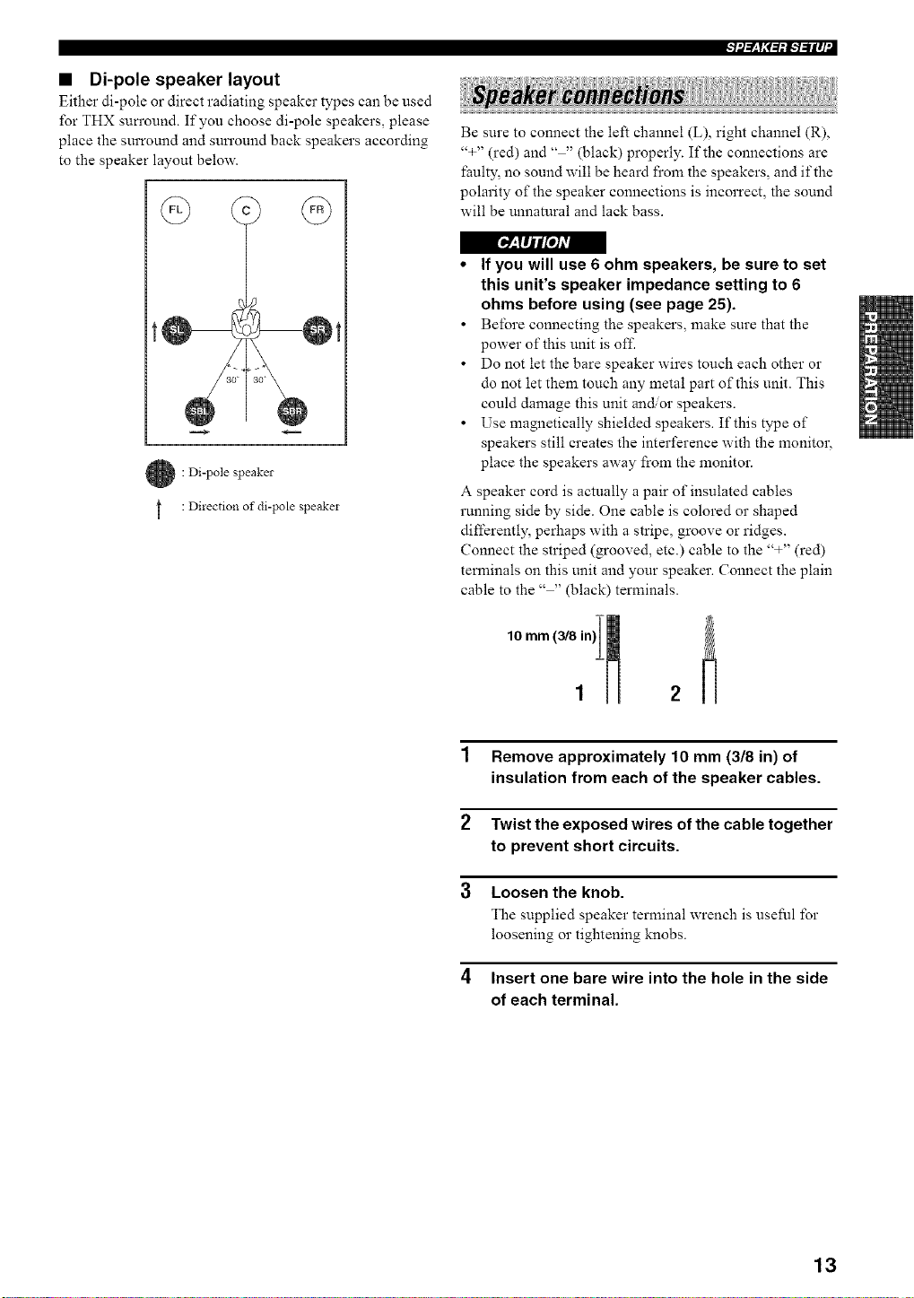
• Di-pole speaker layout
Either di-pole or direct radiating speaker types can be used
for THX sun'ound. If you choose di-pole speakers, please
place the surround and sun'ound back speakers according
to the speaker layout below.
r___fl/tL'o/Avl
: Di-pole speaker
: Direction of di-pole speaker
++l'--_y+,_=,+l,.-b-ilq "I
Be sure to connect the left channel (L), right channel (R),
'%" (red) and .... (black) properly. If the connections are
faulty, no sound will be heard from the speakers, and if the
polarity of the speaker connections is incorrect, the sound
will be unnatural and lack bass.
• If you will use 6 ohm speakers, be sure to set
this unit's speaker impedance setting to 6
ohms before using (see page 25).
• Before connecting the speakers, make sure that the
power of this unit is off.
• Do not let the bare speaker wires touch each other or
do not let them touch any metal part of this unit. This
could damage this unit an_or speakers.
• Use magnetically shielded speakers. If this type of
speakers still creates the interference with the monitor,
place the speakers away from the monitor.
A speaker cord is actually a pair of insulated cables
running side by side. One cable is colored or shaped
differently, perhaps with a stripe, groove or ridges.
Connect the striped (grooved, etc.) cable to the '%" (red)
terminals on this unit and your speaker. Connect the plain
cable to the .... (black) terminals.
1 Remove approximately 10 mm (3/8 in) of
insulation from each of the speaker cables.
2 Twist the exposed wires of the cable together
to prevent short circuits.
3 Loosen the knob.
The supplied speaker terminal wrench is useful for
loosening or tightening knobs.
4 Insert one bare wire into the hole in the side
of each terminal.
13
IF/i/-_y;1-tif-/=/Iq•
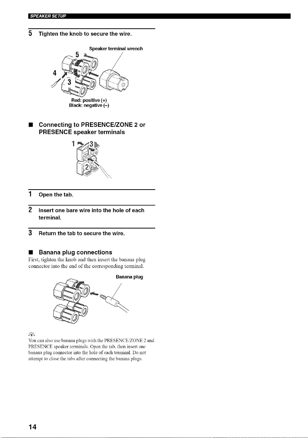
5 Tighten the knob to secure the wire.
4
/
Speaker terminal wrench
/
Red: positive (+)
Black: negative (-)
• Connecting to PRESENCE/ZONE 2 or
PRESENCE speaker terminals
1 Open the tab.
2 Insert one bare wire into the hole of each
terminal.
3 Return the tab to secure the wire.
• Banana plug connections
First, tighten the knob and then insert the banana plug
connector into the end of the corresponding terminal.
Banana plug
/
You can also use banana plugs with the PRESENCE/ZONE 2 and
PRESENCE speaker terminals. Open the tab, then insert one
banana plug cormector into the hole of each terminal. Do not
attempt to close the tabs after connecting the banana plugs.
14
++l'--_y++=,iI,.-+--iIq "I
9 .
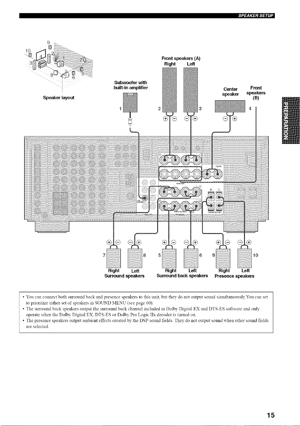
Speaker layout
Subwoofer with
built-in amplifier
Front speakers (A)
Right Left
2 3
Center Front
speaker speakers
(B)
10
Right Left
Presence speakers
• You can connect both surround back and presence speakers to this unit. but they do not output sound simultaneously.You can set
to prioritize either set of speakers in SOLrND MENU (see page 60).
• The surround back speakers output the surround back channel included in Dolby Digital EX and DTS-ES software and only
operate when the Dolby Digital EX, DTS-ES or Dolby Pro Logic IIx decoder is turned on.
• The presence speakers output ambient effects created by the DSP sound fields. They do not output sound when other sound fields
are selected.
15
l'-'lil_Yi'+++l'-'l-"llq"
• FRONT terminals
Connect one or two speaker systems to these terminals. If
you use only one speaker system, connect it to either the
FRONT A or B terminals.
Not+
The Canada model calmot output to two separate speaker systelns
simultaneously.
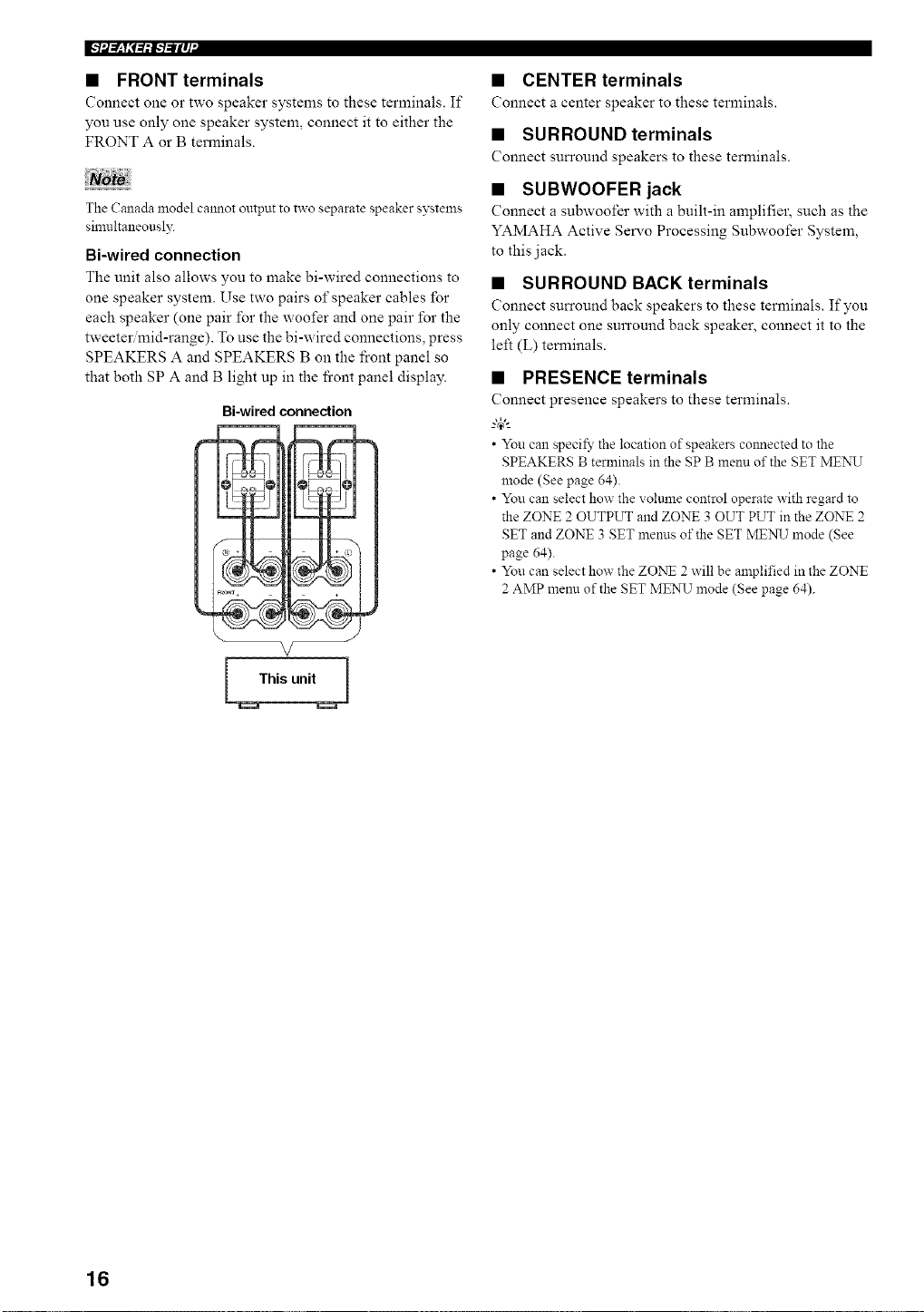
Bi-wired connection
The unit also allows you to make bi-wired connections to
one speaker system. Use two pairs of speaker cables for
each speaker (one pair for the woofer and one pair for the
tweeter mid-range). To use the bi-wired connections, press
SPEAKERS A and SPEAKERS B on the front panel so
that both SP A and B light up in the fi'ont panel display.
Bi-wired connection
This unit
• CENTER terminals
Connect a center speaker to these terminals.
• SURROUND terminals
Connect surround speakers to these terminals.
• SUBWOOFER jack
Connect a subwoofer with a built-in amplifier, such as the
YAMAHA Active Servo Processing Subwoofer System,
to this jack.
• SURROUND BACK terminals
Connect surround back speakers to these terminals. If you
only connect one surround back speaker, connect it to the
left (L) terminals.
• PRESENCE terminals
Connect presence speakers to these terminals.
--'4_'--
• You can specify the location of speakers colmected to the
SPEAKERS B terminals in the SP B menu of the SET MENU
mode (See page 64).
• You can select how the voltmle control operate with regard to
the ZONE 2 OUTPUT and ZONE 3 OUT PUT in the ZONE 2
SET and ZONE 3 SET menus of the SET ME:N_J mode (See
page 64).
• You can select how the ZO:NT 2 will be amplified in the ZONE
2 AMP menn of the SET MENU mode (See page 64).
16
[_: IIHroJAq
Do not connect this unit or other components to the mains
power until all connections between components are
complete.
• Cable indications
For analog signals
le_ analog cables _d_l
right analog cables _a_
For digital signals
optical cables _f[ o2'
coaxial cables ( c [7
For video signals
video cables _
S-video cables _Z_
• Analog jacks
You can input analog signals fi'om audio components by
connecting audio pin cables to the analog jacks on this
unit. Connect red plugs to the right jacks and white plugs
to the left jacks.
• Digital jacks
This unit has digital .jacks lbr direct transmission of digital
signals through either coaxial or fiber optic cables. You
can use the digital jacks to input PCM, Dolby Digital and
DTS bitstreams. When you connect components to both
the COAXIAL and OPTICAL jacks, priority is given to
the input signals from the COAXIAL jack. All digital
input jacks are compatible with 96-kHz sampling digital
signals.
This unit handles digital and analog signals independently. Thus
audio signals input to the analog jacks are only onVput to the
analog OUT (REC)jacks. Likewise audio signals inpm to the
digital (OPTICAL or COAXIAL) jacks are only ontput to the
DIGITAL OUTPUT jacks.
Dust protection cap
Pull out the cap from the optical jack before you connect
the fiber optic cable. Do not discard the cap. When you are
not using the optical jack, be sure to put the cap back in
place. This cap protects the jack from dust.
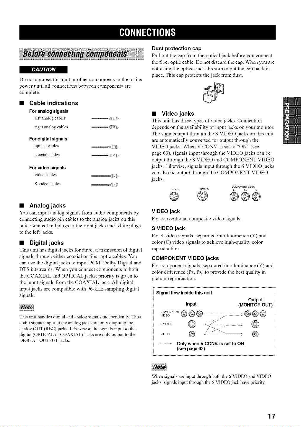
• Video jacks
This unit has three types of video .jacks. Connection
depends on the availability of input jacks on your monitor.
The signals input through the S VIDEO jacks on this unit
are automatically converted for output through the
VIDEO jacks. When V CONV. is set to "ON" (see
page 63), signals input through the VIDEO jacks can be
output through the S VIDEO and COMPONENT VIDEO
jacks. Likewise, signals input through the S VIDEO jacks
can also be output through the COMPONENT VIDEO
jacks.
COMPONENTVIDEO
vmEo SVIDEO p_ p_ g
@ @ @©@
VIDEO jack
For conventional composite video signals.
S VIDEO jack
For S-video signals, separated into luminance (Y) and
color (C) video signals to achieve high-quality color
reproduction.
COMPONENT VIDEO jacks
For component signals, separated into luminance (Y) and
color difference (PB, PR) to provide the best quality in
picture reproduction.
_. ..................................................................................................... i
Signal flow inside this unit !
Output iI
Input (MONITOR OUT) i
S VIDEO
VIDE() ,,
"V\Nensignals are input tl_rough both the S VIDEO and VIDEO
jacks, signals input through the S VIDEO jack have priority.
17
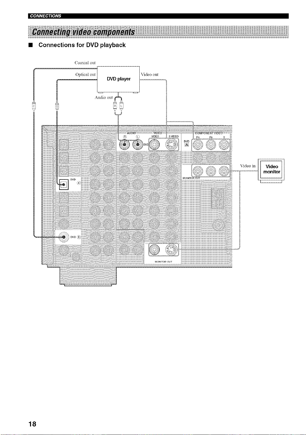
I*_'h'fi'l=i*ilPh'_
• Connections for DVD playback
Coaxial out
Optical out
f
DVD player
Video out
i_!_/i_);!!!iiiiiiiiiiiiiiiiii
!!_??i_i_ii!i!i!i!i!
HHHHHHH
iiiiiiiiiiiii
iiiiiiiiiiii/
HHHHHHii
iiiiiiiiiiiii
HHHHHHH
iiiiiiiiiiiiii
iiiiiiiiiiiii
iiiiiiiiiiii/
iiiiiiiiiiii/
iiiiiiiiiiiii
iiiiiiiiiiiiii
HHHHHHH
iiiiiiiiiiiii
HHHHHHH
iiiiiiiiiiiii
Video in
18
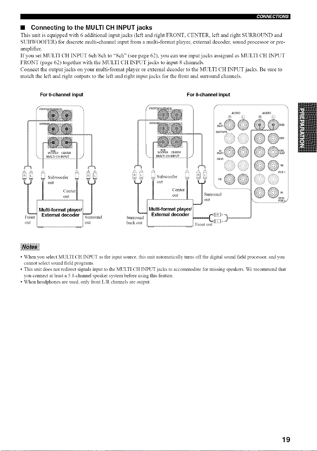
'_'h_liT_lqlpl#
• Connecting to the MULTI CH INPUT jacks
This unit is equipped with 6 additional input jacks (left and right FRONT, CENTER, left and right SURROUND and
SUBWOOFER) for discrete multi-channel input from a multi-format player, external decoder, sound processor or pre-
amplifier.
If you set MULTI CH INPUT 6chi8ch to "8ch" (see page 62), you can use input jacks assigned as MULTI CH INPUT
FRONT (page 62) together with the MULTI CH INPUT jacks to input 8 channels.
Connect the output jacks on your multi-format player or external decoder to the MULTI CH INPUT jacks. Be sure to
match the left and right outputs to the left and right input jacks for the front and surround channels.
For 6-channel input For 8=channel input
0 Subwoofer _
__lt out "
1 centeii T
! o.t L /
Multi-format playerfl I
External decoder _ronnd
l ont
AUDIO
MDffAPg
CD-R
AUDIO
@@o::,
VCR 2
• When you select MULTI CH INPUT as the input source this unit antomaticalh' turns offthe digital sound field processor, and you
cannot select sotmd field prograzns.
T T
• This trait does not redirect signals input to the MULTI CH INPUT jacks to accomznodate _\_rmissing speakers. We reconnnend that
you connect at least a 5.1-channel speaker system be_\_re using this feature.
• When headphones are used. only front ER channels are output.
19
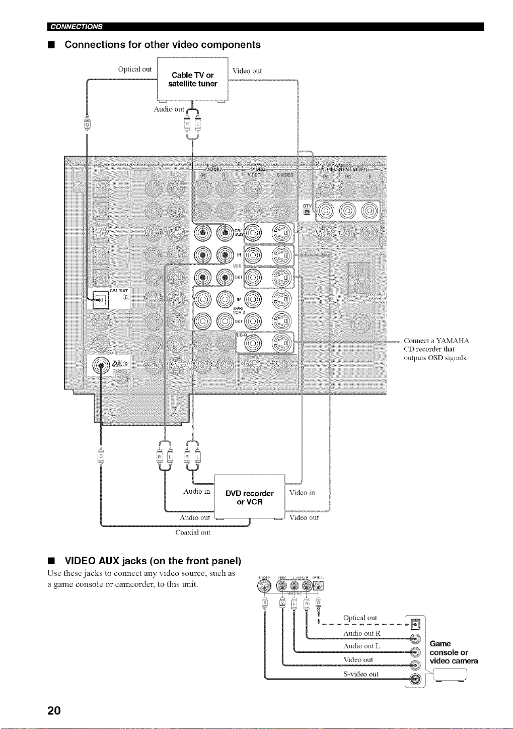
• Connections for other video components
Optical out
Cable TV or
satellite tuner
Audio out
Video out
Coaxial out
Video in
Video out
Connect a YAMAHA
CD recordm flmt
outpms OSD signals.
• VIDEO AUX jacks (on the front panel)
Use these jacks to connect any video source, such as
a game console or camcorder, to this unit.
s,,l_Eo VIDEO L _JE,10_ OPTICAL
g
Optical out
Audio out R
Audio out L
Video out
S-video out
20
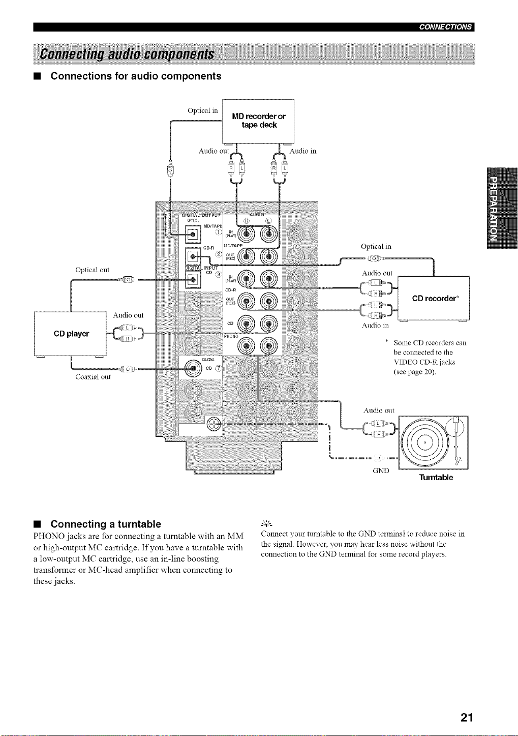
• Connections for audio components
Opticalin[ .._ -- 1
,v,u reeomer or
ped
Audio out,ntrc,C_r__ _r _ia_Audioin
R;!? !i
Optical out
[
CD player
I
Coaxial out
Audio out
Optical in
Audio out 1
CD recorder* /
Audio m
* Some CD recorders can
be connected to the
VIDEO CD-R j acks
(see page 20).
Audio out
i
|
GND
• Connecting a turntable
PHONO jacks are for connecting a turntable with an MM
or high-output MC cartridge. If you have a turntable with
a low-output MC cartridge, use an in-line boosting
transformer or MC-head amplifier when connecting to
these jacks.
Turntable
g_,._
Colmect yonr turntable to the GND terminal to reduce noise in
the signal. However. 5x_umay hear less noise without the
connection to the GND temainal for some record players.
21
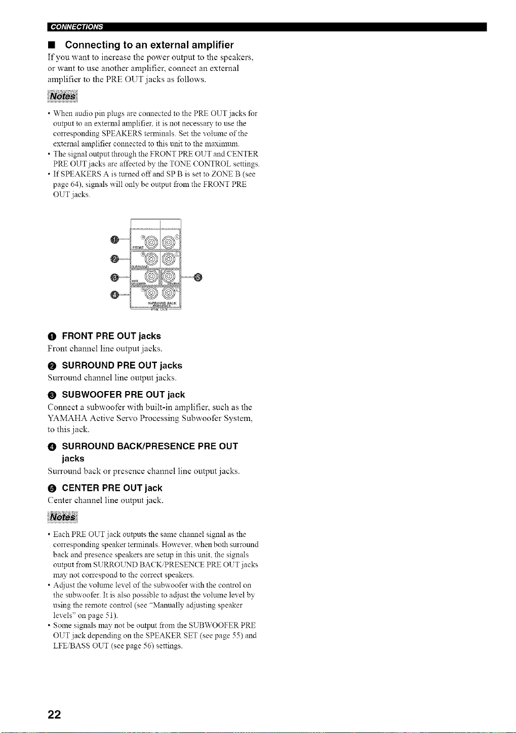
• Connecting to an external amplifier
If you want to increase the power output to the speakers,
or want to use another amplifier, connect an external
amplifier to the PRE OUT jacks as follows.
• When audio pin plugs are connected to the PRE OUT jacks for
output to an external amplifier, it is not necessary to use the
corresponding SPEAKERS terminals. Set the volunle of the
external amplifier connected to this unit to the maxinmm.
• The signal output through the FRONT PRE OUT and CENTER
PRE OUT jacks are affected by the TONE CONTROL settings.
• If SPEAKERS A is turned offand SP B is set to ZONE B (see
page 64), signals will only be untput from the FRONT PRE
OUT jacks.
O ......
@ ............ O
_ROUND _aCK
O FRONT PRE OUT jacks
Front channel line output jacks.
O SURROUND PRE OUT jacks
Sun'ound channel line output jacks.
O SUBWOOFER PRE OUT jack
Connect a subwoofer with built-in amplifier, such as the
YAMAHA Active Servo Processing Subwoofer System,
to this jack.
0 SURROUND BACK/PRESENCE PRE OUT
jacks
Sun'ound back or presence channel line output jacks.
O CENTER PRE OUT jack
Center channel line output jack.
• Each PRE OUT jack outputs the same channel signal as the
corresponding speaker terminals. However, when both surround
back and presence speakers are setup in this unit, the signals
outpm from SURROL_rND BACK/PRESENCE PRE OUT jacks
may not correspond to the correct speakers.
• Actiust the volunae level of the subwoofer with the control on
the subwoofer. It is also possible to adjust the volmne level by
using the remote control (see "Manually ac[iusting speaker
levels" on page 51).
• Some signals may not be output _om the SUBWOOFER PRE
OUT jack depending on the SPEAKER SET (see page 55) and
LFEiBASS OUT (see page 56) settings.
22
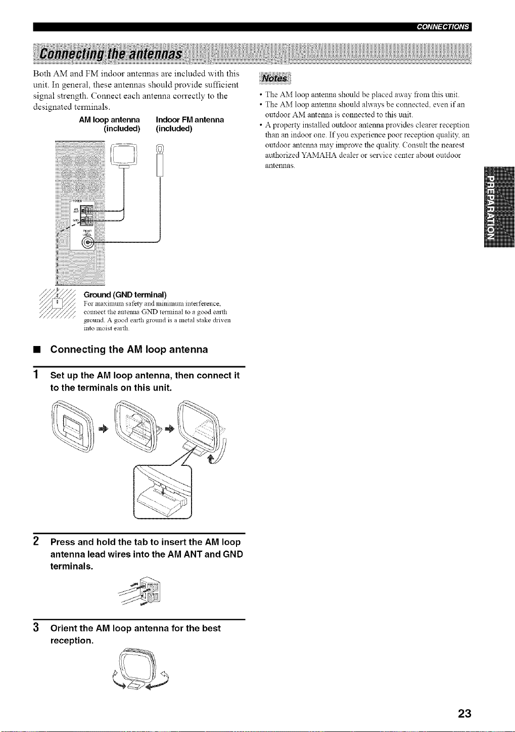
Both AM and FM indoor antennas are included with this
unit. In general, these antennas should provide sufficient
signal strength. Connect each antenna correctly to the
designated temfinals.
AM loop antenna Indoor FM antenna
(included) (included)
• The AM loop antenna should be placed away from this mlit.
• The AM loop antenna should ahvays be connecte& even if an
outdoor AM antemla is connected to this unit.
• A property installed outdoor antenna provides clearer reception
than an indoor one. If you experience poor reception qualit)_ an
outdoor antelma may improve the quality. Consult the nearest
authorized YAMAHA dealer or service center about outdoor
antennas.
Ground (GND terminal)
For maximum safew and zninmluzn interference,
connect the antenna GND terminal to a good earth
ground. A good earth ground is a metal stake driven
into moist earth
• Connecting the AM loop antenna
Set up the AM loop antenna, then connect it
to the terminals on this unit.
÷
2 Press and hold the tab to insert the AM loop
antenna lead wires into the AM ANT and GND
terminals.
3 Orient the AM loop antenna for the best
reception.
23
IN'h'fil=i*ilPh'_
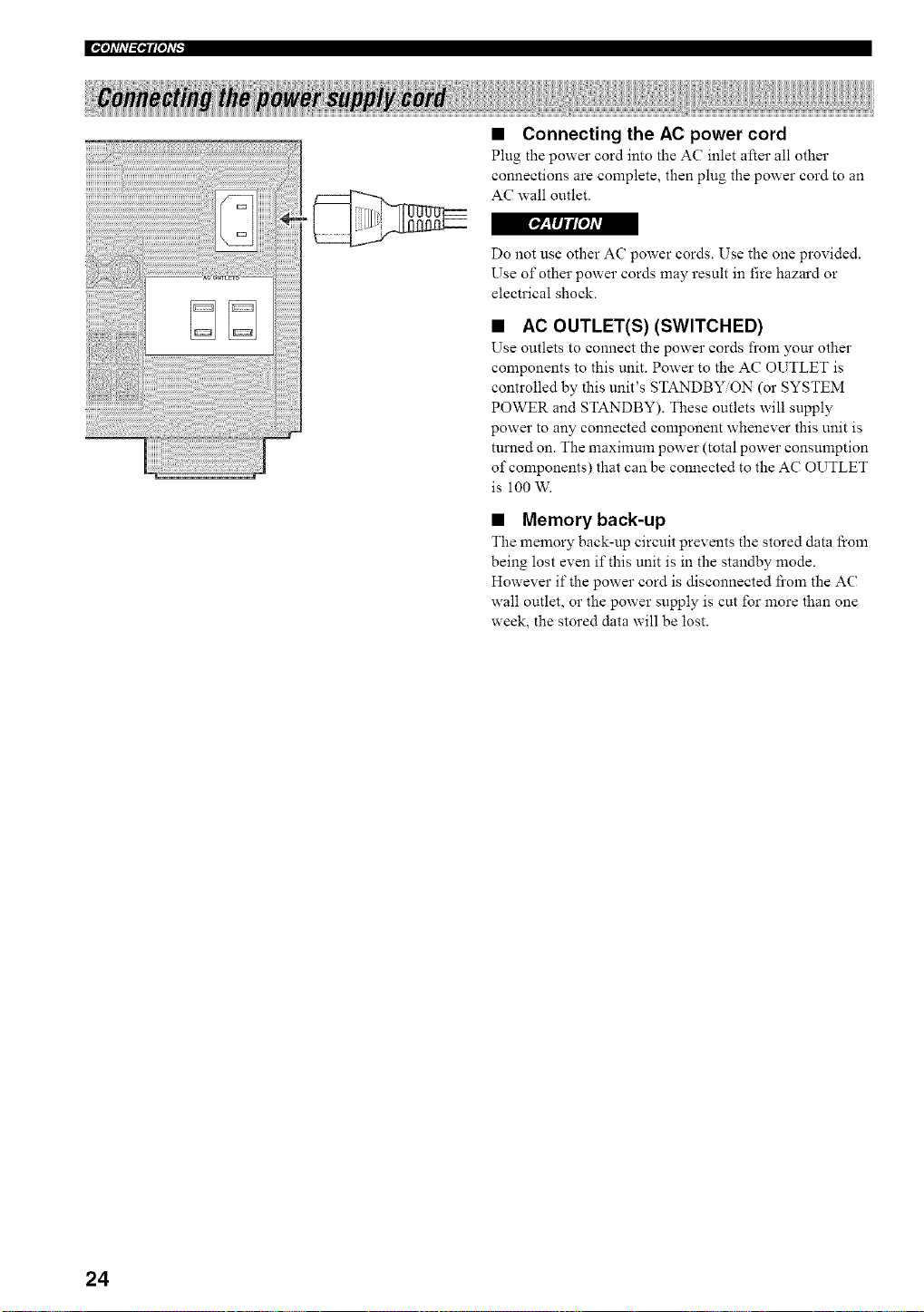
• Connecting the AC power cord
Plug the power cord into the AC inlet after all other
connections are complete, then plug the power cord to an
AC wall outlet.
r_'_lljlt[oJAV_
Do not use other AC power cords. Use the one provided.
Use of other power cords may result in fire hazard or
electrical shock.
• AC OUTLET(S) (SWITCHED)
Use outlets to connect the power cords fi'om your other
components to this unit. Power to the AC OUTLET is
controlled by this unit's STANDBY/ON (or SYSTEM
POWER and STANDBY). These outlets will supply
power to any connected component whenever this unit is
turned on. The maximum power (total power consumption
of components) that can be connected to the AC OUTLET
is 100 W.
• Memory back-up
The memory back-up circuit prevents the stored data from
being lost even if this unit is in the standby mode.
However if the power cord is disconnected fi'om the AC
wall outlet, or the power supply is cut for more than one
week, the stored data will be lost.
24
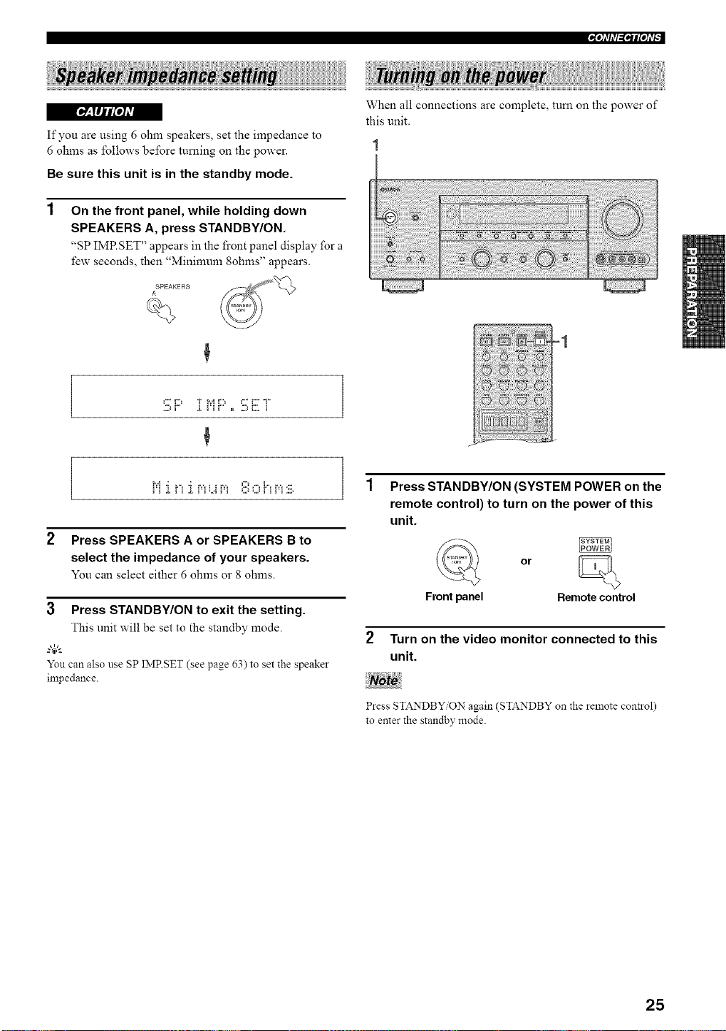
_:lIJl[oJAvA
If you are using 6 ohm speakers, set the impedance to
6 ohms as follows before turning on the power.
Be sure this unit is in the standby mode.
On the front panel, while holding down
SPEAKERS A, press STANDBY/ON.
"SP IMP.SET" appears in the front panel display for a
few seconds, then "Mininmm 8ohms" appears.
SPEAKERS
A
When all connections are complete, turn on the power of
this unit.
C' D T iYiD C ' i:: T
...._ ! .L ! ! ! = ,.,,_ L,, !
i'i .i, ri .i, pi_.,ipi _:::,_.,,_i'ii_i:iil,
2 Press SPEAKERS A or SPEAKERS B to
select the impedance of your speakers.
You can select either 6 ohms or 8 ohms.
=1
3 Press STANDBY/ON to exit the setting.
This unit will be set to the standby mode.
g4,_
Yon can also use SP IMRSET (see page 63) to set the speaker
impedance.
Press STANDBY/ON (SYSTEM POWER on the
remote control) to turn on the power of this
unit.
or
Front panel Remote control
Turn on the video monitor connected to this
unit.
Press STANDBY ON again (STANDBY on the remote control)
to enter the standby mode.
25
This receiver employs YAMAHA Parametric Room
Acoustic Optimizer (YPAO) technology which lets you
avoid troublesome listening-based speaker setup and
achieves highly accurate sound adjustments. The supplied
optimizer microphone collects and analyzes the sound
your speakers produce in your actual listening
environment.
The basic setup feature (page 31) is useful if you want to set up
your system quickly and with minimal effort. However. we
reconmlend that you come back and perform auto setup later to
take advantage of YPAO and el_ioy even higher fidelity.
• Please be advised that it is normal for loud test tones to be
output during the auto setup procedure.
• If auto setup stops and error messages appear on the screen,
i\_llow the troubleshooting on page 29.
YPAO perfomls the following checks and makes
appropriate adjustments to give you the best possible
sound from your system.
WIRING
Checks which speakers are connected and the polarity of
each speaker.
DISTANCE
Checks the distance of each speaker from the listening
position and adjusts the tinting of each channel.
SIZE
Checks the speaker's frequency response and sets the
appropriate low freqnency crossover for each channel.
EQUALIZING
Adjusts frequency and levels of each channel's parametric
equalizer to reduce coloration across the channels and
create a cohesive sound field. This is particularly
important if you use different brands or sizes of speakers
for some channels or have a room with unique sonic
characteristics.
YPAO equalizing calibration incorporates three
parameters (fi'equency, level and Q factor) for each of the
seven bands in its parametric equalizer to provide highly
precise automatic adjustment of frequency characteristics.
LEVEL
Checks and adjusts the sound level (volume) of each
speaker.
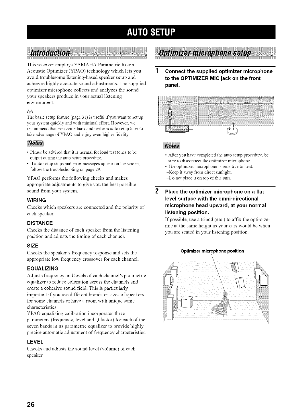
1 Connect the supplied optimizer microphone
to the OPTIMIZER MIC jack on the front
panel.
• After you have completed the auto setup proce&tre, be
sure to discolmect the optimizer microphone.
• The optimizer microphone is sensitive to heat.
Keep it away from direct sunlight.
Do not place it on top of this trait.
Place the optimizer microphone on a flat
level surface with the omni-directional
microphone head upward, at your normal
listening position.
If possible, use a tripod (etc.) to affix the optimizer
mic at the same height as your ears would be when
you are seated in your listening position.
Optimizer microphone position
26
iffll'/"/"ilq'l
For best results, make sure the room is as quiet as possible
during the auto setup procedure (YPAO). If there is too
nmch ambient noise, the results may not be satisfacto W.
"4;'-
Ifyottr subwoofer canadjust the output volume and the crossover
frequency\set the volume to about halfway (or sligNly less) and
set the crossover frequency to the maxilnmn.
VOLUME
©
MIN MA×
CROSSOVER'
HIGH CUT
Subwoofer
1 Switch on this unit and video monitor.
Make sure the OSD is displayed (see page 50).
2 Set AMP/SOURCE/TV to AMP, then press
SET MENU to enter the SET MENU.
[ then
SETME_
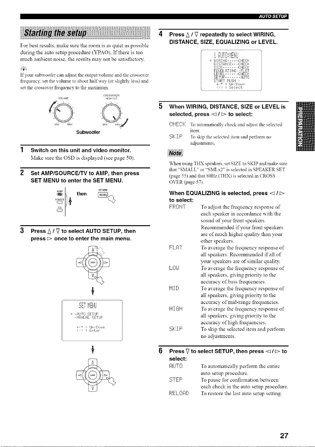
Press k / V to select AUTO SETUP, then
press _:>once to enter the main menu.
+ , +]iJT{i 5ErLIF'
• H61HLII:_LgETLIF'
*/_ ; Up/[:,c,14t-i
Press A / V repeatedly to select WIRING,
DISTANCE, SIZE, EQUALIZING or LEVEL.
_=IH%=I i,g,,__ ii i
÷ idiR!HG ..... CHECK
D! STAHCE,, • CHECk:
SIZE ....... CHE:Ck:
EOLIF,L !Z I HG.. FL_qT
LE:UEL ...... CHECK
SETUF' ..... F_LITO
S]F/RT F'UE;H >
J, _ ; Ul:/[,okIJ*
< " 1: 2,e, le, ct
When WIRING, DISTANCE, SIZE or LEVEL is
selected, press <q / b> to select:
i =1,,,11,,, i =1,,,
,...._,,....,...._'.To autolnatically check and adiustthe selected
item.
,::,"i.." 'r iD
....,_...._., To skip the selected item and pert\ran no
actlustmeuts.
When using THX speakers, set SIZE to SKIP and make sare
that "SMALL" or "SMLx2" is selected in SPEAKER SET
(page 55) and that 80Hz (THX) is selected in (?ROSS
OVER (page 57).
When EQUALIZING is selected, press <1/ c>
to select:
li::'i::'¢'Mi"l'..'...u".'I TO adjust the frequency response of
each speaker in accordance with the
sound of your front speakers.
Recommended if your front speakers
are of much higher quality than your
other speakers.
i:Til....r...,l","F,To average the frequency response of
all speakers. Recommended if all of
your speakers are of similar quality.
,",i.i To average the frequency response of
all speakers, giving priority to the
accuracy of bass frequencies.
i"ii [;, To average the frequency response of
all speakers, giving priority to the
accuracy of mid-range frequencies.
liJl.l.T'...u¢:":iJl To average the frequency response of
all speakers, giving priority to the
accuracy of high frequencies.
....,:n...',,...._.'r,i::' To skip the selected item and perform
no adjustments.
Press _ to select SETUP, then press <_/b> to
select:
r".%.,l="ii"Fl%_'...' To automatically perform the entire
auto setup procedure.
....,:::'-i"i:::i:::,,,,...., To pause for confirmation between
each check in the auto setup procedure.
F;?.(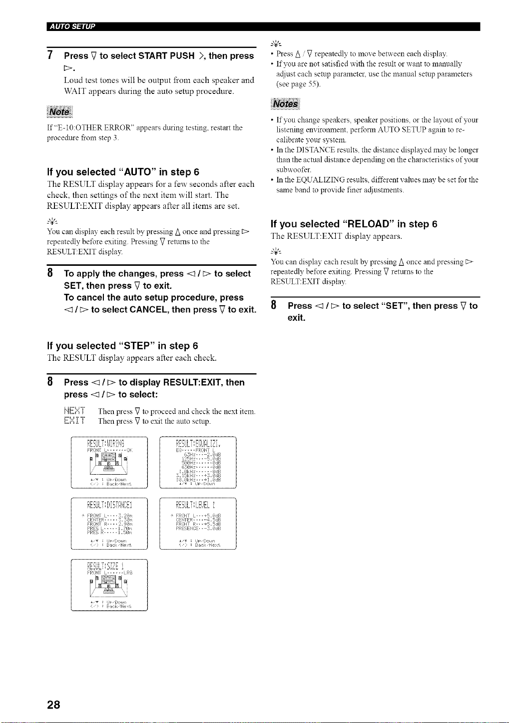
l_lql',l"l"ilq
7 Press V to select START PUSH >, then press
b>.
Loud test tones will be output from each speaker and
WAIT appears during the auto setup procedure.
If"E-10:OTHER ERROR" appears during testing restart the
procedure from step 3.
If you selected "AUTO" in step 6
The RESULT display appears for a few seconds after each
check, then settings of the next item will start. The
RESULT:EXIT display appears after all items are set.
-'T'-
You can display each result by pressing A once and pressing c>
repeatedly be%re exiting. Pressing V returns to the
RESULT:EXIT displa)q
To apply the changes, press <1 / b> to select
SET, then press V to exit.
To cancel the auto setup procedure, press
<1/ b> to select CANCEL, then press V to exit.
"@_
• Press Z_/ V repeatedly to move between each display.
• If you are not satisfied with the result or want to mannally
adiust each setup parameter, use the mamtal setup parameters
(see page 55).
• If you change speakers, speaker positions, or the layout of)z+nr
listening environment, perfoml AUTO SETUP again to re-
calibrate VOtLrsystem.
• In the DISTANCE results, the distance displayed may be longer
than the actual distance depending on the characteristics of )_+nr
subwoofer.
• In the EQUALIZING results, different values may be set for the
same band to provide finer adiustments.
If you selected "RELOAD" in step 6
The RESULT:EXIT display appears.
_.,#._
You can display each result by pressing Z_once and pressing _>
repeatedly be%re exiting. Pressing V returns to the
RESULT:EXIT display.
8 Press <:] / b> to select "SET", then press V to
exit.
If you selected "STEP" in step 6
The RESULT display appears after each check.
Press _/b> to display RESULT:EXIT, then
press <1 / b> to select:
........v, Th p Vt p d d h kth tit
,.,_....,..,+ en ress o rocee an c ec e nex era.
...."" ' Th p gt ittl p_....,..=.+.+ en ress o ex le auto sem .
B:E2St++LT+,[++1+iP{+?
PFONT L, ...... i3[
Ba,:: k, Pe>t
RBULTE+.U£LiL
i+ ..... F'Ri3NT L
6SII;, --2+8,:_F
125P;" • $,@dB
6381-4; _,SB
1,Ok I-_; @,fib
3,15[:i-_; ,, -,3,_dB
÷ FRi)I,tT L-,..3,2@'_
CEI,tTEF,:..... 3, 3;@n
FRONT R,,,. 2, ?@_
PRE5 L ..... 1,78n
PRE5 B:..... 1,5@1'_
¢;_ :J'+ [>oun
Bal< pc1
9??ii "r i ?i++l
÷ FRiZ+_!TL+,+ ,+5,@dB
CEI'+TER...... 4,5dB
FRONT R., ,+5,SdB
PRESENi2E. , +3, @,:JB
• ,T : J FzCcI,@
: B@:k Ne t
D_,++I+IT+,?f?_ i
FROItT L. ..... LPG
Baci, I xt
28
iI'll'/q"ilq'l
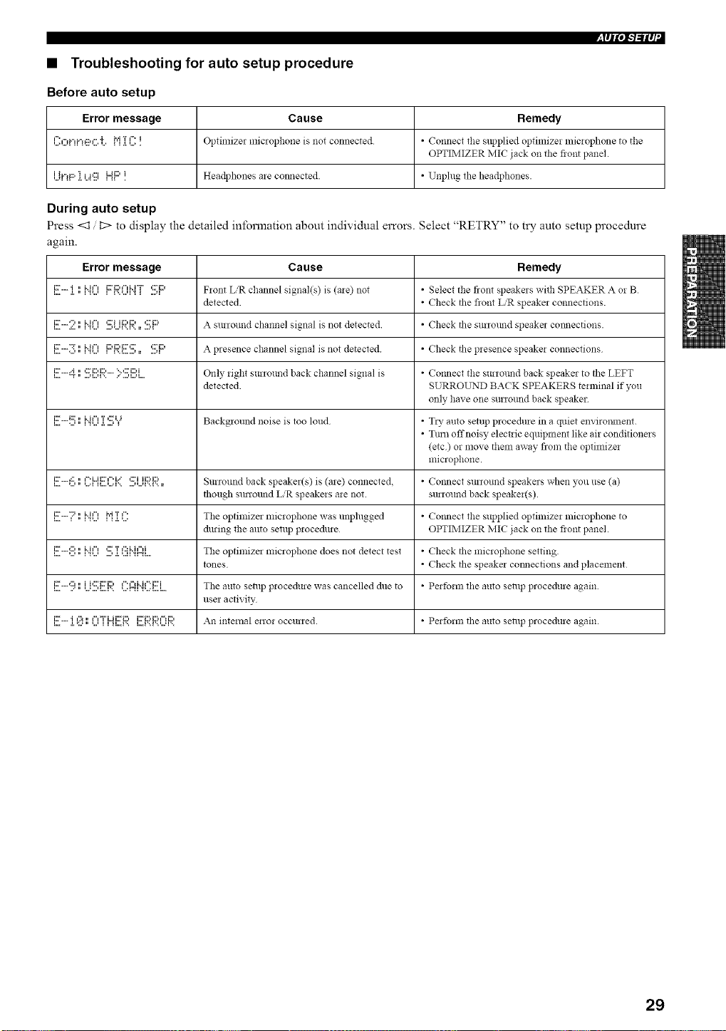
• Troubleshooting for auto setup procedure
Before auto setup
Error message Cause Remedy
{":f"d"d'n:::_f".']'. M T {":i OptilniZel miclopho!le is not connected * Co!lnect tile supplied optimizer lniclophone to tile
OPTIMIZER IVlIC jack on tile fiont panel.
i it"d:::' 'i i =p:::{ {lli"Ji:::'i. Headphones are COllllected. • Unphlg tile headphones.
During auto setup
Press <1 D to display the detailed information about individual errors. Select "RETRY" to try auto setup procedure
again.
Error message Cause Remedy
L.,,i:_" .L • {3_...,'i i { l...,...q 3 _ ...+ql=J Flont L,'R channel signal(s) is (ale) not • Select tile front speakers withSPEAKER A oi B
detected. • Check tile fiont L/R speaker connections.
!!!!-2" !"!'? ,.?...i!:::,.!:::,.. *!!!'!::, A surround channel signal is not detected. • Check tile surrottnd speaker comlections.
,....i:r.....":r....,.",,*...,i"i"",i::'i:::'i:::"::r,...,........,• ....,,,::ri::, A presence channel signal is not detected • Check tile presence speakei co!lnections
I....i::_''"H"T." ....,I...,F..,::."i:::,i:::,.......'"':::'i::)i...,l...q. Only _ight surround back channel signal is • Co,meet tile surwtmd back speaker to tile LEFT
detected. SURROLrND BACK SPEAKERS terminal if you
only have one surwund back speaker
,...i:::".....,::::....,.",i"i""_...,T.,.....,'::r,.=,_ Background noise is too lolld • TI_" alltO setup procedure in a quiet enviwmnent.
• Tirol offnoisy electric equipment like air conditioners
(etc) or move them away flora tile optimizei
microphone.
i...i:::'+:::+...,.",...=i"%"ii:::''q"=.H....,..."r+.....-...+i'..r..,::."i ii:::,i:::,• Surround back speaker(s) is (are) connected. • Co,meet surround speakers when you use (a)
though sunound L'R speakeis aie not. surround back speakeffs).
,....i::....."::=,.",i"i"",,...,,i"_,T.,._...."" The optimizer microphone was unplugged • Colmect the supplied optimize1 microphone to
during the auto setup procedure OPTIMIZER IVIIC jack on tile fiont panel.
,....i:::".....,:::,,...,.",i"i""_,...,....,':::.,.T,...,,":::i"h"'i_,"_,.... Tile optimizer microphone does not detect test • Check tile microphone setting.
tones • Check tile speaker comlections and placement
l...i:r.....,:::, • i i,:::' I:::'i:::,...."'...' ...' _....r.. ,....r'_ 1f" ,=l M f" i:::'i,,...._...., The auto setup procedure was cancelled due to • Perform the auto setup procedure again.
use1 activity
l...i::r..... .l.'i':.._¢:_." _...'f"FT'i"Ji::ri:::,l1 II...I'.. I... I '..i '.. '...q '..i::ri:::'i:::' ¢_li::) All internal enoi occurred. • Perfornl the auto selllp procedure again.
29
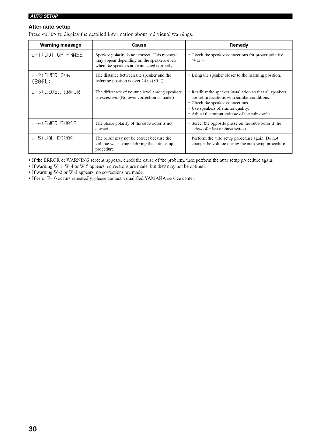
I_lqlOi-'b'ilq
After auto setup
Press <:1 t::> to display the detailed information about individual warnings.
Warning message Cause Remedy
'A*i'i"".l.'i,," '..._'..._¢=liH"I '.Jl¢=d:::' li::d"Jl"P:Fi::Fl1I"I ....q.. Speake: pola:ity is not correct. This message • Check tile speake: connectio!ls fol propel pola:ity
may appear depending on the speakers even (+ or )
when tile speakers are connected correctly.
[ti-:i?. ',1l:_li..i{!!!:l:;:'.24r,=! Tile distance between the speaker and tile • B:ing tile speaker close: to tile listening position.
,'=,:::,,'::,.,::'._", listening position is over 24 m (80 ft)
,.,.*i'i--":r....,,",...,.......,..,..ii::'iii:::'i ,...,...,...,..,,...i:::'i:::'i:::""i:::'The diffe:ence ofvohune level among speake:s • Readjust tile speake: illstallatio!l so that all speake:s
is excessive. (No level correction is made) ate set in locations with sin:ilar conditions
• Check the speaker connections
• Use speakers of similar quality.
• Adjust tile ontput vohnne of tile subwoofe:
,._._i'i""H"r,"....''r'._I,:::"irii:::'i::'l..,li:::'L.i¢"1_:::'i:::'' ''"...'_ Tile phase polarity of the subwoofer is not • Select tile opposite phase on tile subwoofer if the
cor:ect, subwoofe: has a phase switch.
'A'i'i""t::::....'," 'v"'...'l....ii I"li I....1'..F.. '..21'..i::Fi:::,i:::,¢"d:::, Tile lestllt may not be correct because tile • Perform tile auto setup pl ocedlue again Do not
volume was changed du:ing tile auto setup change tile volume during tile auto seia:p p:ocedure.
p:ocedure
• If the ERROR or WARNING screens appears, check the cause of the problem, then perform the auto setup procedttre again.
• If warning W-l, W-4 or W-5 appears, corrections are made. but they may not be optimal.
• If warning W-2 or W-3 appears, no corrections are made.
• If error E-10 occurs repeatedl)_ please contact a qualified YAMAHA service center.
30
The basic system parameters are set automatically when
you run auto setup (page 26). Basic setup is useful if you
want to quickly setup your speakers or to manually adjust
some of the items set in auto setup.
--T--
If you wish to configure the unit lnanually using more precise
adiustments, use the detailed parameters in SOLLND MEN_r
(page 55) instead of BASIC MENU.
Altering any parameters in BASIC MENU will reset all
parameters in SOUND MENU.
3 Press <3 / C> to enter BASIC MENU.
4
When ROOM is selected, press <3 / c> to
change the setting.
Select the size of the room you have installed your
speakers in. Roughly speaking, the room sizes are
defined as follows:
S (small) 16 x 13 It, 200 ft2 (4.8 x 4.0 m, 20 m 2)
h'i(medium) 20 x 16 ft, "2300 It (6Jx5.0m, 30m 2)
,i....(large) 26 x 19 ft, 450 ft 2 (7.9 x 5.8 m, 45 m 2)
-1
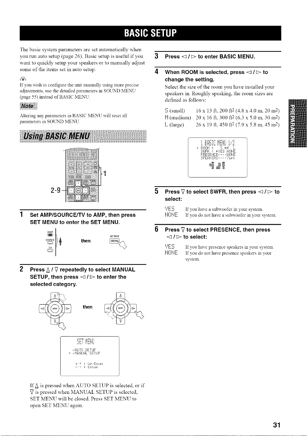
2=9 `
Set AMP/SOURCE/TV to AMP, then press
SET MENU to enter the SET MENU.
_EI) _ then
Press A / V repeatedly to select MANUAL
SETUP, then press <3 / c> to enter the
selected category.
• AUTO SETLIF'
e ,HI:IilUF, L SETLIF'
Ul [:lOLih
<- ; ] i"d:,_:,l
E,H:,oo,,,L,o s;,,'.,
ROOH : S H'I L
- -r=, _'?ES:, k, _ ML-ME
clJ iF'RESEiEE,.. I],.,E
SPEAKERS .... 7:Fk
_N NN
Press _7to select SWFR, then press <3 / c> to
select:
"_"{:::.::::, If you haxe a subwoofer in },our systeln.
I,,11 I I,, 1 I,,,
,".-...,,".,,.... If you do not have a subwoofer in your system.
Press V to select PRESENCE, then press
<3 / c> to select:
"/'.c.b If you have presence speakers in ?,our system
I,,11 I I,, 1 I,,,
,".,,...,,".,,.... If you do not haxe presence speakers in ?,our
systeln.
IfA is pressed when AUTO SETUP is selecte& or if
V is pressed when MANUAL SETUP is selected,
SET MENU will be closed. Press SET MENU to
open SET MENU again.
31
l:+F/pl-'/-'ilq '
Choices
2
:3
4
5
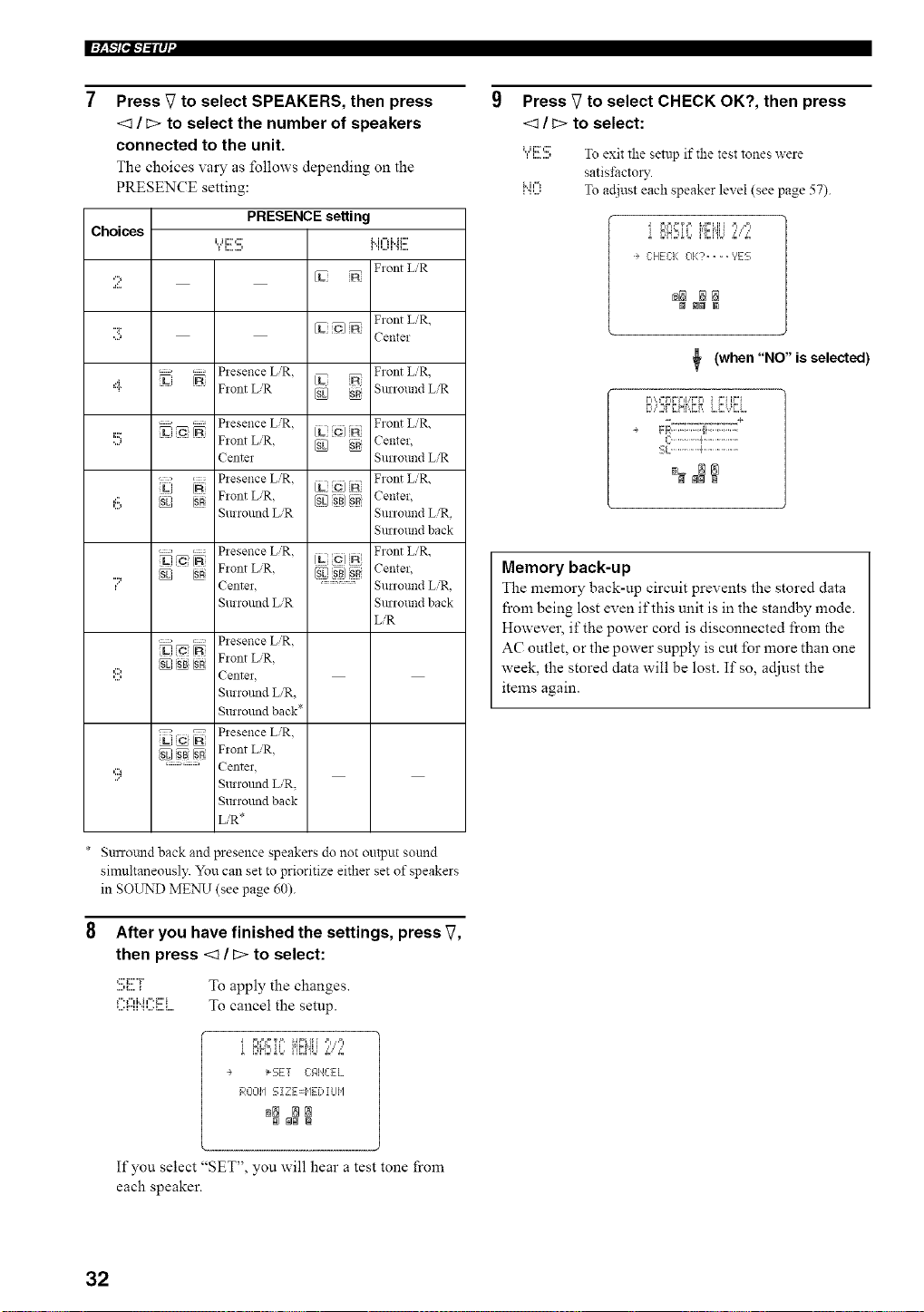
Press V to select SPEAKERS, then press
<_ / c> to select the number of speakers
connected to the unit.
The choices vary as follows depending on the
PRESENCE setting:
PRESENCE setting
Flont L'R
VL
Front L]R,
[L O]
Center
............. Piesence L]R.
Fiont LiR
Front L'R.
Surround L/R
........... Piesence LiR.
Flont L_R. _ 'SR
Centel
Plesence L,'R.
SR Fiont L/R. _E]_1 SR[
Suriound L,'R
............. Plesence L,'R.
U ic IN c) _ A
N Flont L,'R, [g_ ssJ N
Center. .............
Suriound L/R
Front L/R,
Center,
Sunound LiR
Front L/R,
Center,
Surround L/R,
Surround back
Front L/R,
Center,
Sunound L/R,
Surround back
LiR
. Presence L]R,
_[SB}_+ Front L,,'R,
Center
Surromid LR,
Surround back*
'c; _ Piesence LiR.
S{SL/ _ [SR Fiont L_R.
=:=: Center,
Surromid L/R,
Surround back
L/R*
* Surrotmd back and presence speakers do not output sound
simultaneously. You can set to prioritize either set of speakers
in SOUND ME_N_T(see page 60).
After you have finished the settings, press V,
then press <1 / c> to select:
:!!!;i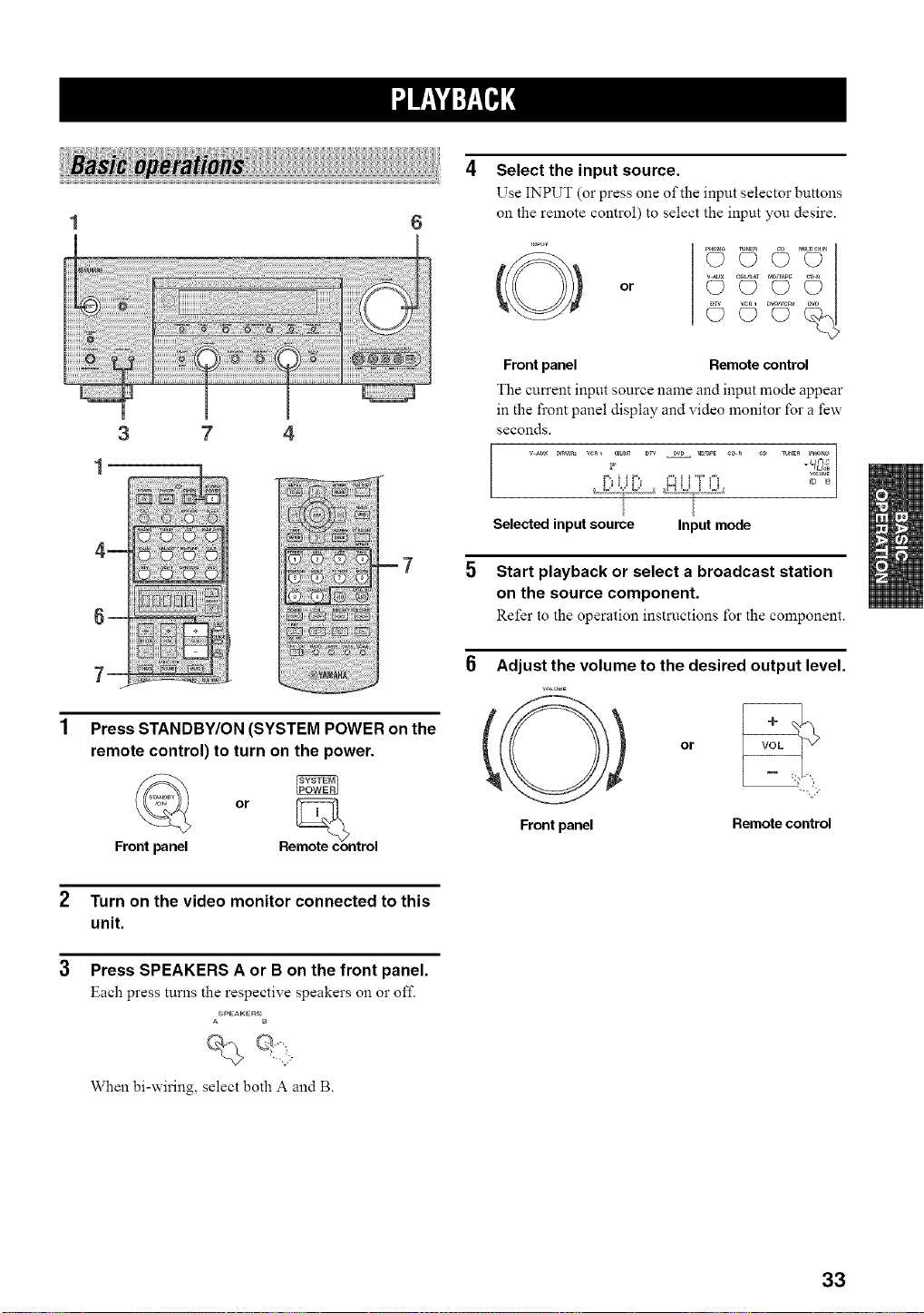
3 7 4
1
Press STANDBY/ON (SYSTEM POWER on the
remote control) to turn on the power.
or moth,con
Front panel Re trol
2 Turn on the video monitor connected to this
unit.
3 Press SPEAKERS A or B on the front panel.
Each press turns the respective speakers on o1"off.
ASPEAKERS
When bi-wiring, select both A and B.
Select the input source.
Use INPUT (or press one of the input selector buttons
on the remote control) to select the input you desire.
or
(D C) C? _
Frontpanel Remotecontrol
The current input source name and input mode appear
in the front panel display and video monitor for a few
seconds.
Selectedinputsource Inputmode
5 Start playback or select a broadcast station
on the source component.
Refer to the operation instructions for the component.
6 Adjust the volume to the desired output level.
VOL_,,,E
Frontpanel
or VOL
--..., '>
Remote control
33
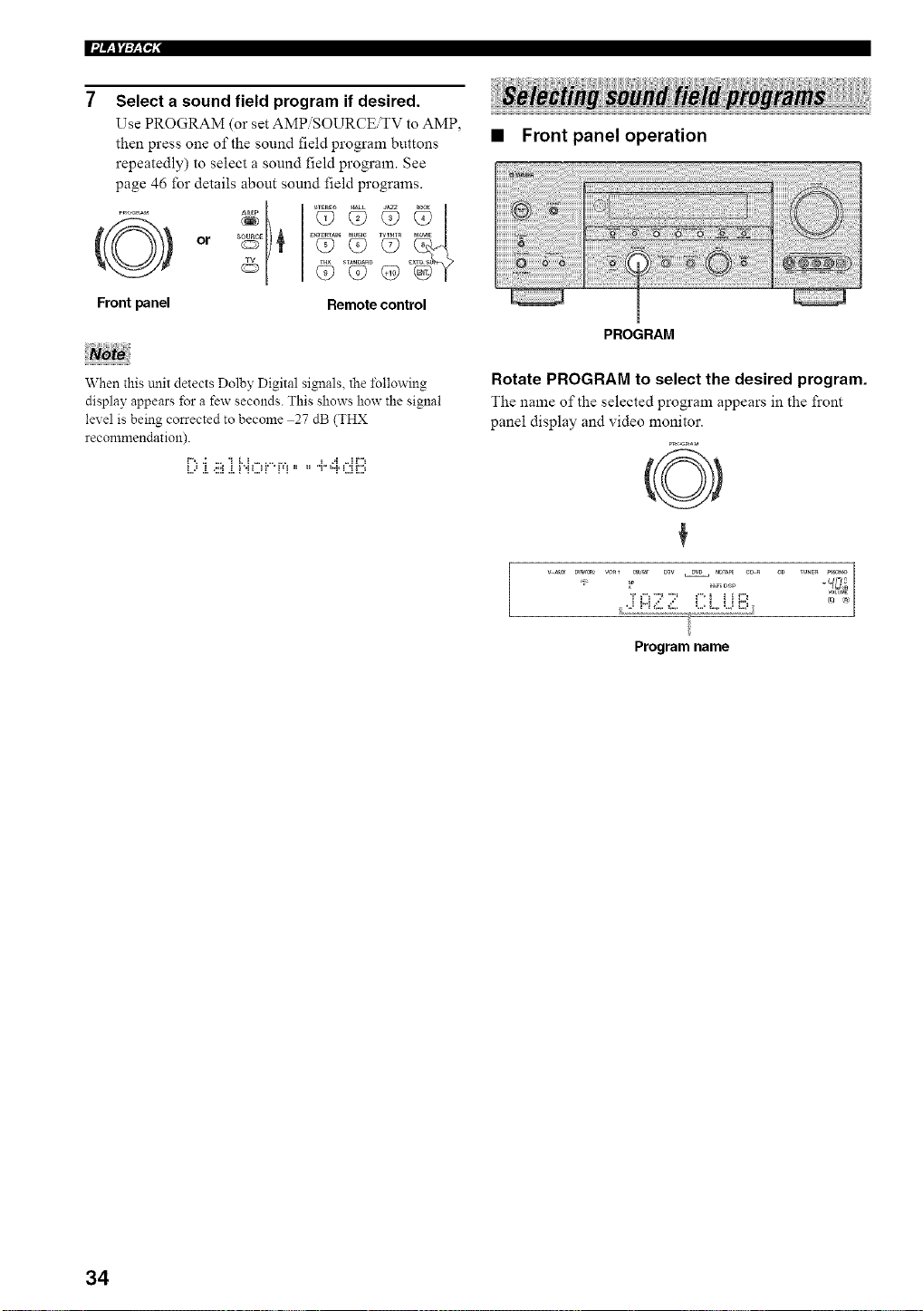
Front panel
Select a sound field program if desired.
Use PROGRAM (or set AMPiSOURCEiTV to AMP.
then press one of the sound field program buttons
repeatedly) to select a sound field program. See
page 46 for details about sound field programs.
or }
Remote control
• Front panel operation
When this unit detects Dolby Digital signals, the l\_llowing
display appears for a few seconds. This shows how the signal
level is being corrected to become 27 dB (THX
recommendation).
i..==.i.<::i.i.i "iLJf ' i=i " " T ="i'L;iD
PROGRAM
Rotate PROGRAM to select the desired program.
The name of the selected program appears in the front
panel display and video monitor.
0
/ ,.i H _:_,._:_,. L.=L. U i2'J
Program name
34
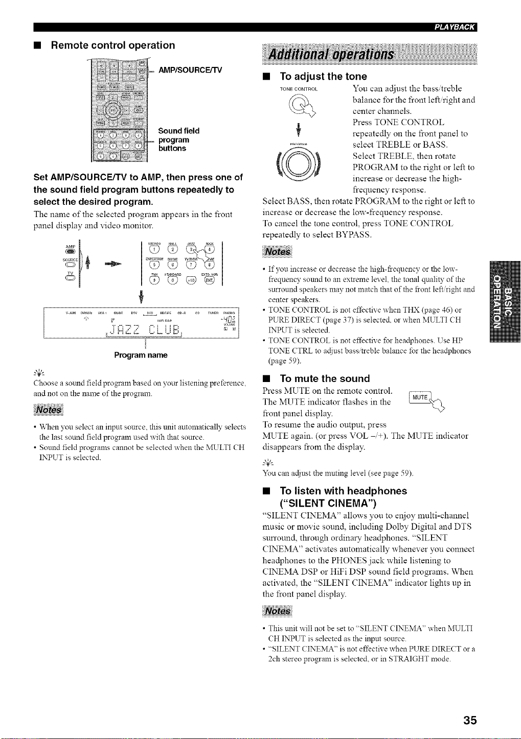
• Remote control operation
AMP/SOU RCE/TV
Sound field
program
buttons
Set AMP/SOURCE/TV to AMP, then press one of
the sound field program buttons repeatedly to
select the desired program.
The name of the selected program appears in the front
panel display and video monitor.
<> <> G>EV°
¢
_ _R_ w_l CBb_ DTV DV_ M_PE CD_ eD TU_E_ PH_
_OLW*E
Program name
Choose a sound field program based on your listening preference,
and not on the name of the program.
• When you select an input source, this unit automatically selects
the last sound field program used with that source.
• Sound field programs cannot be selected when the MULTI CH
INPUT is selected.
• To adjust the tone
TONECOmROL You can adjust the bass treble
balance for the front left right and
center channels.
Press TONE CONTROL
repeatedly on the fi'ont panel to
........... select TREBLE or BASS.
Select TREBLE, then rotate
PROGRAM to the right or left to
increase or decrease the high-
frequency response.
Select BASS, then rotate PROGRAM to the right or left to
increase or decrease the low-frequency response.
To cancel the tone control, press TONE CONTROL
repeatedly to select BYPASS.
• If you increase or decrease the high-ffeqnency or the low-
frequency sound to an extreme level, the tonal qnality of the
surround speakers may not match that of the front left/right and
center speakers.
• TONE CONTROL is not effective when THX (page 46) or
PURE DIRECT (page 37) is selecte& or when MULTI CH
INPUT is selected.
• TONE CONTROL is not effective for headphones. Use HP
TONE CTRL to ac{iustbass/treble balance for the headphones
(page 59).
• To mute the sound
Press MUTE on the remote control.
The MUTE indicator flashes in the
front panel display.
To resume the audio output, press
MUTE again. (or press VOL _+). The MUTE indicator
disappears from the display.
-"4_"-
You can ac{iust the nmting level (see page 59).
• To listen with headphones
("SILENT CINEMA")
"SILENT CINEMA" allows you to enjoy multi-channel
music or movie sound, including Dolby Digital and DTS
sun'ound, through ordinary hea@hones. "SILENT
CINEMA" activates automatically whenever you connect
hea@hones to the PHONES jack while listening to
CINEMA DSP or HiFi DSP sound field programs. When
activated, the "SILENT CINEMA" indicator lights up in
the front panel display.
• This unit will not be set to "SILENT CINEMA" when */RTLTI
CH INPUT is selected as the input source.
• "SILENT CINEMA" is not effective when PURE DIRECT or a
2ch stereo program is selected, or in STRAIGHT mode.
35
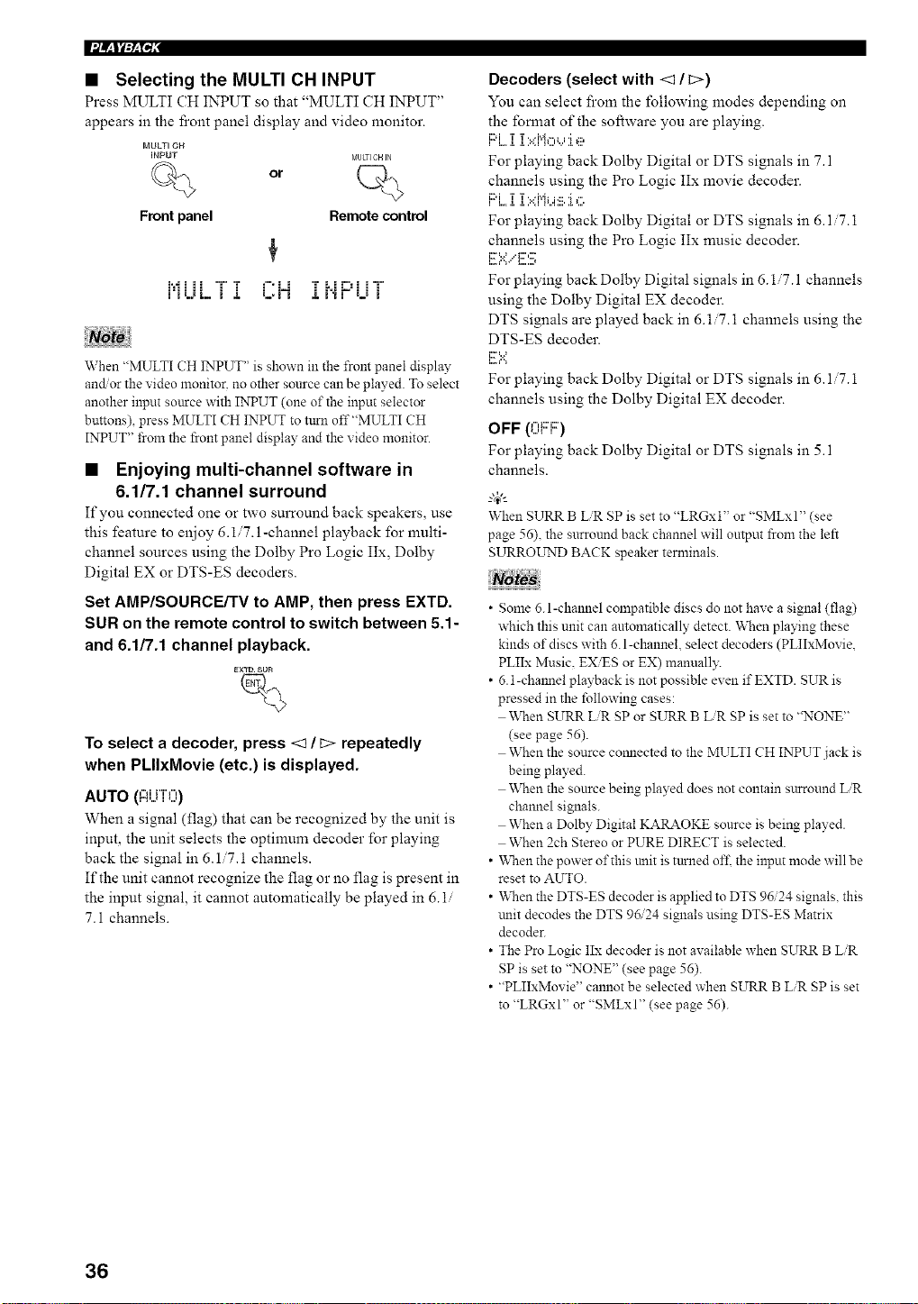
• Selecting the MULTI CH INPUT
Press MULTI CH INPUT so that "MULTI CH INPUT"
appears in the l]contpanel display and video monitor.
MULTI OH
INPUT MULTICHJN
or
Front panel
Remote control
i'iLJL i J. L,i'i ,i, i'iV i l i
When "MULTI CH INPUT" is shown in the from panel display
andor the video monitor, no other source can be played. To select
another input source with INPUT (one of the input selector
buttons) press MULTI CH INPUT to turn off"MULTI CH
INPUT" from the front panel display and the video monitor.
• Enjoying multi-channel software in
6.1/7.1 channel surround
If you connected one or two surround back speakers, use
this feature to enjoy 6.1.7.1-channel playback for multi-
channel sources using the Dolby Pro Logic IIx, Dolby
Digital EX or DTS-ES decoders.
Set AMP/SOURCE/TV to AMP, then press EXTD.
SUR on the remote control to switch between 5.1-
and 6.1/7.1 channel playback.
To select a decoder, press <1 / i;> repeatedly
when PLIIxMovie (etc.) is displayed.
AUTO (l:ii..jTO)
When a signal (flag) that can be recognized by the unit is
input, the unit selects the optimum decoder for playing
back the signal in 6.1/7.1 channels.
If the unit cannot recognize the flag or no flag is present in
the input signal, it cannot automatically be played in 6.1/
7.1 channels.
Decoders (select with <1 / t>)
You can select froln the following modes depending on
the fomlat of the software you are playing.
I"G....I. I.>d'qo_J I e
For playing back Dolby Digital or DTS signals in 7.1
channels using the Pro Logic IIx movie decoder.
i i..,, a..i ..............
For playing back Dolby Digital or DTS signals in 6.1 7.1
channels using the Pro Logic IIx music decoder.
i:r=.:.:**...'i:::''::_
For playing back Dolby Digital signals in 6.17.1 channels
using the Dolby Digital EX decoder.
DTS signals are played back in 6.1 7. i channels using the
DTS-ES decoder.
F :.<
For playing back Dolby Digital or DTS signals in 6.1 '7. i
channels using the Dolby Digital EX decoder.
OFF (OF'F::)
For playing back Dolby Digital or DTS signals in 5.1
channels.
When SURR BUR SP is set to "LRGxl" or "SMLxl" (see
page 56), the surround back channel will output from the left
SURROL_TNDBACK speaker terminals.
• Some 6.l-channel compatible discs do not have a signal (flag)
which this unit can automatically detect. When playing these
kinds of discs with 6. l-channel, select decoders (PLIIxMovie,
PLIIx Music. EXiES or EX) manuall?:
• 6.1-chmmel playback is not possible even if EXTD. SUR is
pressed in the following cases:
When SURR LiR SP or SURR BUR SP is set to "NONE"
(see page 56).
When the source comlected to the MULTI CH INPUT jack is
being played.
When the source being played does not contain surround LiR
channel signals.
When a Dolby Digital KARAOKE source is being played.
When 2ch Stereo or PURE DIRECT is selected.
• "When the power of this unit is turned of£ the input mode will be
reset to AUTO.
• When the DTS-ES decoder is applied to DTS 96/24 signals, this
trait decodes the DTS 96/24 signals using DTS-ES Matrix
decoder.
• The Pro Logic IIx decoder is not available when SURR B LiR
SP is set to "NONE" (see page 56).
• "PLIIxMovie" cannot be selected when SURR B LiR SP is set
to "LRGxl" or "SMLxI" (see page 56).
36
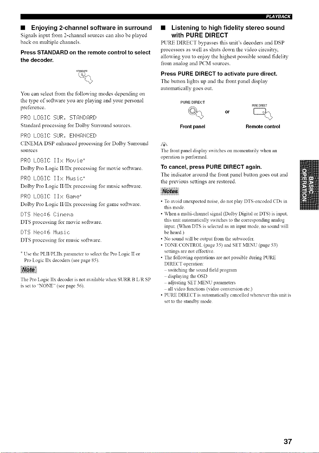
• Enjoying 2-channel software in surround
Signals input from 2-channel sources can also be played
back on multiple channels.
Press STANDARD on the remote control to select
the decoder.
_AN_A_D
%
You can select fi'om the following modes depending on
the type of software you are playing and your personal
preference.
Standard processing for Dolby Surround sources.
_:::,i:::.",i ,-.':::T,-. ,:::'iii:::, i::r_..iL.i,-,_..i,".i::ri-,
CINEMA DSP enhanced processing for Dolby Surround
sources
i:::'F;;:0L.0(!!ii(?iT':.::i"i,:::,,...,:i.,ii_*
Dolby Pro Logic II,IIx processing for movie software.
i:::,i:::,_"l i ¢"ff::: T ¢" T T. • i'd i j ....; ¢.. *
•, .................. • ,, ,,, .... , ,, ,,.,
Dolby Pro Logic II,IIx processing for nmsic software.
!:::'!::;:9L..'?(!!:.]?2i[?i:..:l!_.ii_r,_e*
Dolby Pro Logic II,IIx processing for game software.
[)"[:!!!:i"4,1x,',',=!!,_":'i_.",,:::,r,',.::_
DTS processing for movie software.
[)"[:!!!:i"4eo',',6 _,'i_J.:::.'i,".
DTS processing for nmsic software.
T
* Use the PLII PLIIx parameter to select the Pro Logic II or
Pro Logic IIx decoders (see page 85).
The Pro Logic IIx decoder is not available when SURR B LR SP
is set to "NONE" (see page 56).
• Listening to high fidelity stereo sound
with PURE DIRECT
PURE DIRECT bypasses this unit's decoders and DSP
processors as well as shuts down the video circuitry,
allowing you to enjoy the highest possible sound fidelity
from analog and PCM sources.
Press PURE DIRECT to activate pure direct.
The button lights up and the front panel display
automatically goes out.
PORE DIRECT
PURE DIRECT
% or [_
Front panel Remote control
The front panel display switches on momeutarily when an
operation is pertbrmed.
To cancel, press PURE DIRECT again.
The indicator around the front panel button goes out and
the previous settings are restored.
• To avoid unexpected noise, do not play DTS-encoded CDs in
this mode.
• \,_]len a multi-chmmel signal (Dolby Digital or DTS) is input,
this unit automatically switches to the corresponding analog
input. (When DTS is selected as an input mode. no sotmd will
be heard.)
• No sound will be output from the subwoofer.
• TONE CONTROL (page 35) and SET MENU (page 53)
settings are not effective.
• The following operations are not possible during PURE
DIRECT operation:
switching the sound field program
displaying the OSD
adjusting SET MENU parameters
all video fi.mctions (video conversion etc.)
• PURE DIRECT is automatically cancelled whenever this unit is
set to the standby mode.
37
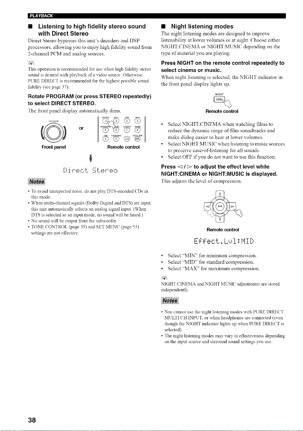
Ifl/_l_:_l"i,"
• Listening to high fidelity stereo sound
with Direct Stereo
Direct Stereo bypasses this unit's decoders and DSP
processors, allowing you to enjoy high fidelity sound from
2-channel PCM and analog sources.
This operation is recommended for use when high fidelity stereo
sound is desired with playback of a xideo source. Otherwise.
PURE DIRECT is recommended for the highest possible sound
fidelity (see page 37).
Rotate PROGRAM (or press STEREO repeatedly)
to select DIRECT STEREO.
The fi'ont panel display automatically dims.
Front panel
_TEREO HALL d_
l_Tm_ M_E
or E Q? Q?
Remote control
[-"..: .......... i. =" *i.............
• To avoid unexpected noise, do not play DTS-encoded CDs in
this mode.
• When multi-chamlel signals (Dolby Digital and DTS) are input,
this trait automatically selects an analog signal input. (\_&en
DTS is selected as an input mode. no sound will be heard.)
• No sotmd will be output from the subwoofer.
• TONE CONTROL (page 35) and SET MENU (page 53)
settings are not effective.
• Night listening modes
The night listening modes are designed to improve
listenability at lower volumes or at night. Choose either
NIGHT:CINEMA or NIGHT:MUSIC depending on the
type of material you are playing.
Press NIGHT on the remote control repeatedly to
select cinema or music.
When night listening is selected, the NIGHT indicator in
the front panel display lights up.
NIGHT
Remote control
• Select NIGHT:CINEMA when watching fihns to
reduce the dynamic range of film soundtracks and
make dialog easier to hear at lower volumes.
• Select NIGHT:MUSIC when listening to music sources
to preserve ease-of-listening for all sounds.
• Select OFF if you do not want to use this function.
Press <1 / _> to adjust the effect level while
NIGHT:CINEMA or NIGHT:MUSIC is displayed.
This adjusts the level of compression.
Remote control
i"'l",l"* ...... ,i, 1 , ,'i , 1,,,IT i",,
_:::.T' ".."=:::'L.*L. ==L.,'...'J. ==J'l J.L.'
• Select "MIN" for minimum compression.
• Select "MID" for standard compression.
• Select "MAX" for maxinmm compression.
-"4"-
NIGHT:CINEMA and NIGHT:MUSIC ac[iustments are stored
independently.
• You calmot use the night listening modes with PURE DIRECT,
MULTI CH INPUT. or when headphones are connected (even
though the NIGHT indicator lights up when PURE DIRECT is
selected).
• The night listening modes may vary in effectiveness depending
on the input source and snrround sound settings you use.
38
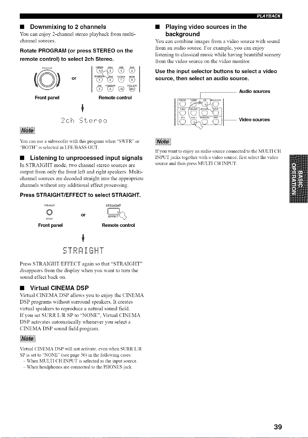
• Downmixing to 2 channels
You can enjoy 2-channel stereo playback from multi-
channel sources.
Rotate PROGRAM (or press STEREO on the
remote control) to select 2ch Stereo.
Front panel
E_ WT_ _lE
or Q? Q?
Remote control
You can use a subwoofer with this program when "SWFR" or
"BOTH" is selected in LFE BASS OUT.
• Listening to unprocessed input signals
In STRAIGHT mode, two channel stereo sources are
output fi'om only the front left and right speakers. Multi-
channel sources are decoded straight into the appropriate
channels without any additional effect processing.
Press STRAIGHT/EFFECT to select STRAIGHT.
ST_aE{;m STRAIGHT
© or
EffECT
Front panel Remote control
"=', i P,=""L=I i i'_ P=I i
Press STRAIGHT EFFECT again so that "STRAIGHT"
disappears from the display when you want to turn the
sound effect back on.
• Virtual CINEMA DSP
Virtual CINEMA DSP allows you to enjoy the CINEMA
DSP programs without surround speakers. It creates
virtual speakers to reproduce a natural sound field.
If you set SURR LR SP to "NONE", Virtual CINEMA
DSP activates automatically whenever you select a
CINEMA DSP sound field program.
• Playing video sources in the
background
You can combine images fi'om a video source with sound
from an audio source. For example, you can enjoy
listening to classical music while having beautiful scenery
from the video source on the video monitor.
Use the input selector buttons to select a video
source, then select an audio source.
Audio sources
--------------------Video sources
If you want to eujoy an audio source connected to the MULTI CH
INPUT jacks together with a video source, first select the video
source and then press MULTI (H INPUT.
Virtual CINEMA DSP will not activate, even when SURR LiR
SP is set to "NONE" (see page 56) in the following cases:
When MULTI CH INPUT is selected as the input source.
When headphones are connected to the PHONES jack.
39
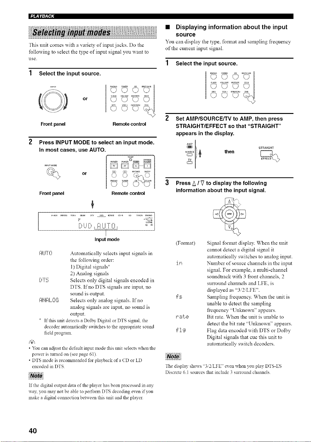
This unit comes with a variety of input jacks. Do the
following to select the type of input signal you want to
1.lse.
Select the input source.
(@) or
Front panel
..........Z¢I
C} O
© c>....o
Remote control
or
Front panel
Press INPUT MODE to select an input mode.
In most cases, use AUTO.
o
_o_to I_NEN CO 7_eHIN
Remote control
|
Input mode
Ai...iTO Automatically selects input signals in
the fbllowing order:
1) Digital signals*
2) Analog signals
I;,T:!!; Selects only digital signals encoded in
DTS. If no DTS signals are input, no
sound is output.
I:::Ii".iI::ii..o08 Selects only analog signals. If no
analog signals are input, no sound is
output.
* If this unit detects a Dolby Digital or DTS signal, the
decoder automatically switches to the appropriate sound
field program.
• You can acliust the default input mode this tulit selects when the
power is turned on (see page 61).
• DTS mode is reconmlended for playback of a CD or LD
encoded in DTS.
If the digital output data of the player has been processed in an?"
way. you may not be able to peri\mn DTS decoding even if you
make a digital connection between this unit and the player.
• Displaying information about the input
source
You can display the type, format and sampling frequency
of the current input signal.
Select the input source.
.............2¢1
c? c)
© c).... c9
Set AMP/SOURCE/TV to AMP, then press
STRAIGHT/EFFECT so that "STRAIGHT"
appears in the display.
%El) _ then
Press A / V to display the following
information about the input signal.
(Format) Signal format display. When the unit
cannot detect a digital signal it
automatically switches to analog input.
:i.iq Number of source channels in the input
signal. For example, a multi-channel
soundtrack with 3 front channels, 2
surround channels and LFE, is
displayed as "3i2iLFE".
",::':ii_. Sampling frequency. When the unit is
unable to detect the sampling
frequency "Unknown" appears.
i...ii_i;e Bit rate. When the unit is unable to
detect the bit rate "Unknown" appears.
",::'][g Flag data encoded with DTS or Dolby
Digital signals that cue this unit to
automatically switch decoders.
The display shows "3i2iLFE" even when you play DTS-ES
Discrete 6.1 sources that include 3 sttrround channels.
40
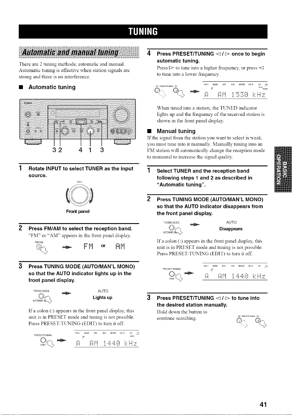
There are 2 tuning methods; automatic and manual.
Automatic tuning is effective when station signals are
strong and there is no interference.
• Automatic tuning
32 41 3
Rotate INPUT to select TUNER as the input
source.
Front panel
Press FM/AM to select the reception band.
"FM" or "AM" appears in the front panel display.
FIvl/AM
F H or RH
Press TUNING MODE (AUTO/MAN'L MONO)
so that the AUTO indicator lights up in the
front panel display.
TUNING MODE AUTO
Lights up
Ifa colon C) appears in the front panel display, this
unit is in PRESET mode and tuning is not possible.
Press PRESET TI_'ING (EDIT) to turn it of£
ve_ CBb_ DW _D Ma_PE e_a CD 2
PRES£TrrUNING _ AUTO
Press PRESET/TUNING <1 / c> once to begin
automatic tuning.
Press _2>to tune into a higher frequency, or press <1
to tune into a lower frequency.
VC_l CBb_ DTV DW M_AP_ ¢_ _ ¢D T_
When tuned into a station, the TIJNED indicator
lights up and the l_cequency of the received station is
shown in the front panel display.
• Manual tuning
If the signal fi'om the station you want to select is weak,
you must tune into it manually. Manually tuning into an
FM station will automatically change the reception mode
to monaural to increase the signal quality.
1 Select TUNER and the reception band
following steps 1 and 2 as described in
"Automatic tuning".
Press TUNING MODE (AUTO/MAN'L MONO)
so that the AUTO indicator disappears from
the front panel display.
I'tlNING f¢ODE _ AUTO
Disappears
Ifa colon C) appears in the front panel display, this
unit is in PRESET mode and tuning is not possible.
Press PRESET TUNING (EDIT) to turn it off.
PRESErgUNING _
i,,,_ !'_ ! ! .!, "T "P_L,_ r,, ! !aL,
Press PRESET/TUNING <1 / c> to tune into
the desired station manually.
Hold down the button to
continue searching.
41
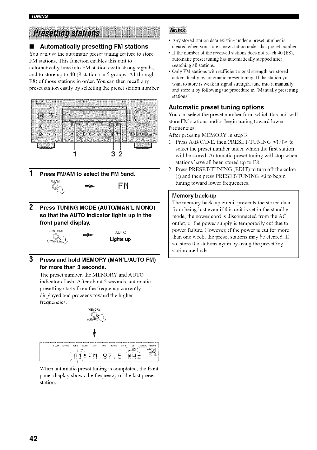
llq_,'#_,'+'
+++++++ ++++++i+++!+!+!+++;++i+i++ii
• Automatically presetting FM stations
You can use the automatic preset tuning feature to store
FM stations. This function enables this unit to
automatically tune into FM stations with strong simaals,
and to store up to 40 (8 stations in 5 groups, A1 through
E8) of those stations in order. You can then recall any
preset station easily by selecting the preset station number.
1 32
1 Press FM/AM to select the FM band.
FM/AM
W' m',"+
i=i'i
Press TUNING MODE (AUTO/MAN'L MONO)
so that the AUTO indicator lights up in the
front panel display.
TUNING MODE AUTO
Lights up
Press and hold MEMORY (MAN'L/AUTO FM)
for more than 3 seconds.
The preset number, the MEMORY and AUTO
indicators flash. After about 5 seconds, automatic
presetting starts from the frequency cun'ently
displayed and proceeds toward the higher
frequencies.
MEMORY
• Any stored station data existing under a preset number is
cleared when you store a new station trader that preset number.
• If the number of the received stations does not reach 40 (ES),
automatic preset tnning has antomatically stopped after
searching all stations.
• Only FM stations with sufficient signal strength are stored
automatically by automatic preset tuning. If the station you
want to store is weak in signal strength, tune into it manually
and store it by following the procedure in "Manually presetting
stations".
Automatic preset tuning options
You can select the preset number from which this unit will
store FM stations and.or begin tuning toward lower
frequencies.
After pressing MEMORY in step 3:
1 Press A/B/C/DiE, then PRESET/TUNING <1 / t:> to
select the preset number under which the first station
will be stored. Automatic preset tuning will stop when
stations have all been stored up to E8.
2 Press PRESET/TUNING (EDIT) to turn off the colon
(:) and then press PRESET/TUNING <1 to begin
tuning toward lower frequencies.
Memory back-up
The memory back-up circuit prevents the stored data
from being lost even if this unit is set in the standby
anode, the power cord is disconnected from the AC
outlet, or the power supply is temporarily cut due to
power failure. However, if the power is cut for more
than one week, the preset stations may be cleared. If
so, store the stations again by using the presetting
station methods.
++. _TO_,_ _mr ¸,
+,"_ _ I+ + ++ _+l +. ,+ ++++ _:,,
+
When automatic preset tuning is completed, the front
panel display shows the fi'equency of the last preset
station.
42
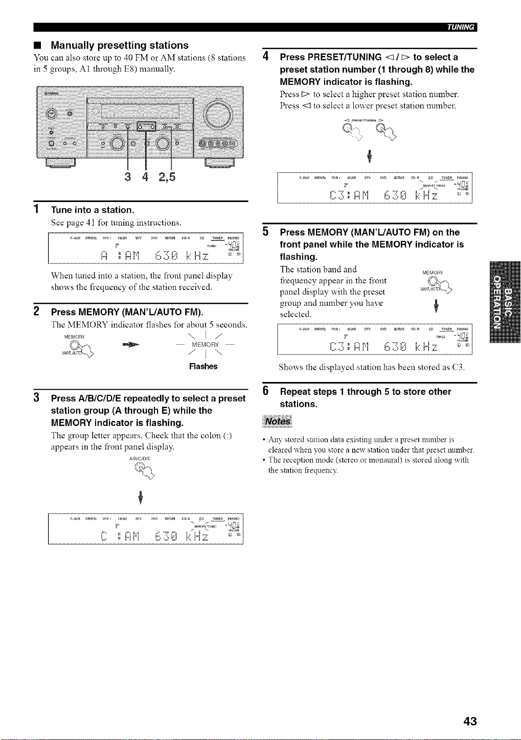
• Manually presetting stations
You can also store up to 40 FM or AM stations (8 stations
in 5 groups, A1 through E8) manually.
3 4 2,5
1 Tune into a station.
See page 41 for tuning instructions.
v m× _r_ VC_l e_r Dw pro M_T_PE C_ _ ¢D T_mE_ PH_O
Vm,_E
H _ H _q O ,.2__:[J i':. i"i ,¢'
When tuned into a station, the front panel display
shows the frequency of the station received.
2
Press MEMORY (MAN'IJAUTO FM).
The MEMORY indicator flashes for about 5 seconds.
MEMOR_ \ I /
MEMORY
/ I \
Flashes
Press AIBICIDIE repeatedly to select a preset
station group (A through E) while the
MEMORY indicator is flashing.
The group letter appears. Check that the colon C)
appears in the front panel display.
A/B,'C/D/E
B_
Iqi'#i'_'
Press PRESET/TUNING <1 / c> to select a
preset station number (1 through 8) while the
MEMORY indicator is flashing.
Press 12> to select a higher preset station number.
Press <3 to select a lower preset station number.
5 Press MEMORY (MAN'L/AUTO FM) on the
front panel while the MEMORY indicator is
flashing.
The station band and _o_¥
fi'equency appear in the front
panel display with the preset
group and number you have
selected.
,....-:,., ,...,_..._ ......:,.,..:, _._i...._"° --_%
Shows the displayed station has been stored as C3.
Repeat steps 1 through 5 to store other
stations.
• Any stored station data existing under a preset number is
cleared when you store a new station under that preset number.
• The reception mode (stereo or monaural) is stored along with
the station frequency.
43
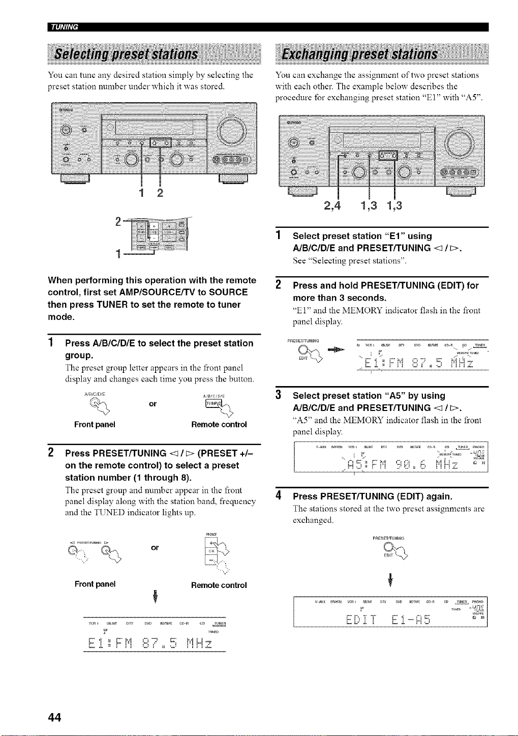
You can tune any desired station simply by selecting the
preset station number under which it was stored.
You can exchange the assignment of two preset stations
with each other. The example below describes the
procedure lbr exchanging preset station "E 1" with "A5".
1 2
2,4 1,3 1,3
When performing this operation with the remote
control, first set AMP/SOURCE/TV to SOURCE
then press TUNER to set the remote to tuner
mode.
Press A/BICIDIE to select the preset station
group.
The preset group letter appears in the fi'ont panel
display and changes each time you press the button.
,_JB/C/DiE
A/_/C/B/E
or
Front panel Remote control
Press PRESET/TUNING <1 / _> (PRESET +/-
on the remote control) to select a preset
station number (1 through 8).
The preset group and number appear in the front
panel display along with the station band, frequency
and the TUNED indicator lights up.
or
PRBEY
Front panel Remote control
vcR1 C_L_T _W DW raD,_ c_ c_ TU_E_
_P runE_
1 Select preset station "El" using
A/BICIDIE and PRESET/TUNING <1/c>.
See "Selecting preset stations".
Press and hold PRESET/TUNING (EDIT) for
more than 3 seconds.
"El" and the MEMORY indicator flash in the front
panel display.
PRESE_rUNIHG
nl vci_ _.................. ....... 9......
i2..i. ,, r" i'i ,::2,!' ,, ..J i'i r"i Z.
Select preset station "A5" by using
A/BICIDIE and PRESET/TUNING <1/c>.
"A5" and the MEMORY indicator flash in the front
panel display.
!"! ,.J _ ! ! ! .,," _:,3 _ _.,,_ ! ! ! ! &,
4 Press PRESET/TUNING (EDIT) again.
The stations stored at the two preset assignments are
exchanged.
W,_3 [ [ W, [ "'H,_
44
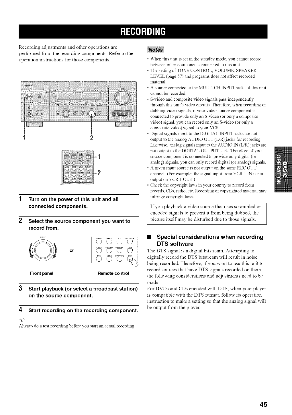
Recording adjustments and other operations are
performed from the recording components. Refer to the
operation instrnctions for those components.
1 Turn on the power of this unit and all
connected components.
2 Select the source component you want to
record from.
O
Front panel
or
©©
Remote control
3 Start playback (or select a broadcast station)
on the source component.
4 Start recording on the recording component.
Ahvays do a test recording before yon start an actual recording.
• \_len this unit is set in the standby mode, you calmot record
between other components co_mected to this unit.
• The setting of TONE CONTROL VOLUME. SPEAKER
LEVEL (page 57) and progranls does not affect recorded
material.
• A source colmected to the MULTI CH INPUT jacks of this unit
cannot be recorded.
• S-video and composite video signals pass independently
through this tmit's video circuits. Therefore, when recording or
dubbing video signals, if your video source component is
connected to provide only an S-video (or only a composite
video) signal, you can record only an S-video (or only a
composite video) signal to your VCR.
• Digital signals input to the DIGITAL INPUT jacks are not
ontput to the analog AUDIO OUT (L/R) jacks for recording.
Likewise. analog signals input to the AUDIO IN (L/R)j acks are
not output to the DIGITAL OUTPUT jack. Thereibre. if your
source component is connected to provide only digital (or
analog) signals, yon can only record digital (or analog) signals.
• A given input source is not output on the same RE(; OUT
channel. (For example, the signal input from VCR 1 IN is not
output on VCR 1 OUT.)
• Check the cop xTight laws in your count15 to record from
records. CDs, radio, etc. Recording of cop3Tighted material may
infringe copyright laws.
If you playback a video source that uses scrambled or
encoded signals to prevent it from being dubbed, the
picture itself may be disturbed due to those signals.
• Special considerations when recording
DTS software
The DTS signal is a digital bitstream. Attempting to
digitally record the DTS bitstream will result in noise
being recorded. Therefore, if you want to use this unit to
record sources that have DTS signals recorded on them,
the following considerations and adjustments need to be
lllade.
For DVDs and CDs encoded with DTS, when your player
is compatible with the DTS format, follow its operation
instruction to make a setting so that the analog signal will
be output fi'om the player.
45
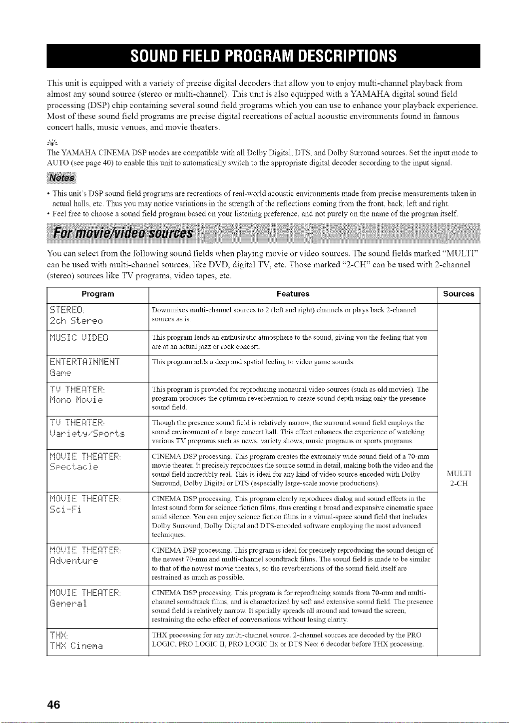
This unit is equipped with a variety of precise digital decoders that allow you to enjoy multi-channel playback fi'om
ahnost any sound source (stereo or multi-channel). This unit is also equipped with a YAMAHA digital sound field
processing (DSP) chip containing several sound field progrmns which you can use to enhance your playback experience.
Most of these sound field programs are precise digital recreations of actual acoustic environments found in famous
concert halls, music venues, and movie theaters.
g4;--
The YAMAHA CINEMA DSP modes are compatible with all Dolby Digital, DTS, and Dolby Sttrround sources. Set the inpnt mode to
AUTO (see page 40) to enable this trait to automatically switch to the appropriate digital decoder according to the input signal.
• This unit's DSP somld field pro_ams are recreations of real-world acoustic em ironlnents made from precise measurements taken in
actual halls, etc. Thus yon may notice xariations in the strength of the reflections coming from the front, back, left and right.
• Feel free to choose a sound field program based on yoar listening preference, and not purely on the name of the program itself.
You can select from the following sound fields when playing movie or video sources. The sound fields marked "MULTI"
can be used with multi-channel sources, like DVD, digital TV, etc. Those marked "2-CH" can be used with 2-channel
(stereo) sources like TV programs, video tapes, etc.
Program Features Sources
',:::,_ _"...._"'",........_' Dowmnixes multi-channel sources to 2 (left and figh0 channels or plays back 2-channel
:_?.,::;{"i¢::'i',,::ai."._:::,_", sources as is.
ii"_i_,,,.<,,,,b:::'Ta,,,,..¢_"',..",_._,,'_,,,,,,,.,ii 'r r',,i:::',=_ This program lends an enthusiastic atnlospheie to tile sound, giving you tile feeling that _vou
are at an actual jazz or rock concmt.
i:::'i..r'r'¢:'i:::,"r'_",..,_...=. r ..".,'ri.ii.,.ii:::'i.rT'.....,. This program adds a deep and spatial feeling to video game sounds
l.:i.ii_i'qe
{!.) {{"1[::.H I _2:._:':'.. Thisprogramisprovidedf_rieproducingmonauralvideosomces(suchasoldmovies).The
N,"_i.",", i"h"_.._'i _:::, program pro&rues the optimum reverberation to create sound depth using only the presence
sound field.
"Fivi "i%,,ii:::'n"l"i%2:'i:::,,,,,.,.... ... Thollgh tile presence sound field is relatively_ nanow, tile stlrlolllld SOUlldfield employs tile
{J.::ai.".i ,::a'i'._...i/'::.;;:._",i."d'..:::. sound environment of a large concert hall. This effect enhances file experience of watching
various TV programs such as news, variety shows, music programs o! spozts programs.
,.m......u,.............' "" ' "a_"_ ' ="" _....... CINEMA DSP processing. This program creates the extrelnely wide sotmd field of a 70-rain
'.!!:';F::'eG 'i7...iii!G ]. ,ii? movie theater. It precisely, ieproduces the source somM in detail, making bo_'h the video and the
sound field incredibly real. This is ideal for any kind of video source encoded with Dolby MULTI
Surround Dolby Digital or DTS (especially, la*ge-scale movie productions). 2-CH
i.eh'_i......iT..............i:::""i%..ii:::'f"C'Pi:::"i:::,... CINEMA DSP processing. This program clearly *eproduces dialog and souud effects in tile
'.!!1,:::,:i.-F:::i. latest sotmd fbrm tbr science fiction fihns, thus creating a broad and expansive cinematic space
amid silence. "z_u can enjoy science fiction fihns in a virtual-space sottod field that includes
Dolby Surround, Dolby Digital and DTS-encoded softwaie employing tile most advanced
techniques.
,.m......u,.....' "" _ "a_"_......._ ' ="" _....... CINEMA DSP processing. This program is ideal for precisely, reproducing the sotmd design of
l._n"41.Ji:::,i.=l'h.ii.%::5 the newest 70-ram and multi-channel smmdt*ack fihns. The sound field is made to be simila*
to that of the newest movie theate*s, so tile *everbe*ations of the sotmd field itself are
*estrained as much as possible.
,.m......u,.............' "" ' "a_"_ ' ="" _....... CINEMA DSP processing. This prog!am is for reproducing sounds from 70-rain and multi-
l.!_,ii?i...!ei._qi!]. channel soundtrack fihns and is characterized by, soft and extensive sound field. The presence
sound field is relatively narrow It spatially spreads all around and towa*d the screen,
*estraining the echo effect of conve*sations without losing cla*ity
"ri..a==...... THX processing for any multi-cham_el source. 2-cham_el sources are decoded bv_ the PRO
"ri..a='.'=f": i i.-.::ar,',.:::, LOGIC, PRO LOGIC II. PRO LOGIC IIx or DTS Neo: 6 decode* before THX processing.
46
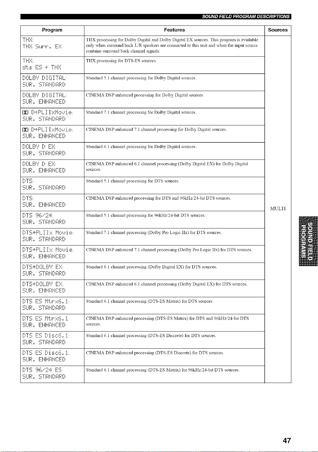
-'Iol#ldl_l_l=lm_J_:[oItq:V-qJ_ll_l_;-"f_l:tl_i£oJd_
Program Features Sources
"i"i...i=:...... THX p:ocessin_ for Dolbv_ Digital and Dolby Digital EX sources. This program is available
"i"U==:.:=='!!!;i...#"q.".,= i!!!==:.:== only when sunound back LIR speakers are connected to this unit and when the input so:uce
contains surro:md back channel si_:als
"i"i..i==...... THX processing, tbr DTS-ES sources
.=J.i.... i::,::' .i.. "i"i..J% =
,...'u,...,...,i'.,,",i i.::,u, ,...'i'*._.'r_...,":::"r.,."r,",i_r",, " Standa:d 5 1 channel processing for Dolby Digital sources.
l...._...,l....l...,i%f",i i::,i.Jl l....i%._.'r,...,":::T.,."i",",i=,",, . CINEMA DSP eilhanced processing, fo: Dolbv_ Digital SOllrces
,:Fi ii::, E:i..ii..M"lMl='i::r ',
Flll l..:'"l"l"'l....l..I.::'::P'I':::'L.;I':::': Standard7 1 channelprocessing for DolbyDigital sources.
,:Fi ii::, <:' "i" =='d..ir'., =='d:)r'.,
Fill l:::'+F::q...:i::i:::.::Mo'.,':i.e: CINEMA DSP etzhanced 7 1 channel processing fo: Dolby Digital sources.
'::_iii:;:',. F'i'._i,,4gli',,if":F'r':,
l..='=...'l...l..._i'd"di::,i..ll i%.. K::'=....=....=. Ntandard () l channel proeessi!lg fol Dolby Digital sol3rces.
,::Fi ii:::, _:::'"1" f"l M r',, f"l K::,P,
l..='Ul...,l..._i'd"di::,i..lli%.=i:::'=....=....=. CINEMA DSP enhanced 6 1 channel processing (Dolby Digital EX) fo: Dolby Digital
,::."i ii:::, i:::'i..ii=Jl"iM f_.E:'r ',, SOllrces
i%T,,=.....':" gtandaid 5 1 channel processing for DTS SOlUCes
....ll,,,ll'., l: .,,,i _ i"_i ,ii,,,,l,,_l,,,i,,,
i%T,:::',,...... CINE_IA DSP enhanced p:ocessing for DTS and 96kHz/24-bit DTS sources,
,:::'i ii:::, i:::'M i..Jf"_i.. i _-'i:::' r'.,
MULTI
i::,"i"'.!!;9'=.!!.":;?:"!. Standa:d 5 1 channel processing tbr 96kHz/24-bit DTS sources
.... _1,,,11', , ii ,,,,I _ I"_I 'H,,,'p_l',,i,,,
' F:,"r'q..H=:'i 'r'i":.:' i"i,",,..,'i,::_. 'Standard7 1 channelprocessing(DolbyP:oLogiclIx) t_:DTSsources.
...._,,,11'.. l: .,,i _ i"_i ,ii,,,,l,,_l,,,i,,,,
i:)T:!!i"PF:'L.:[T':.:: Mo'...':i.,::_: CINEMA DSP enhanced 7 1 channel processing (Dolby P:o Logic IIx) t): DTS sources
':Ei ii:;;'., i:::'b_i-41:::IHl-:i:::'i":,
r"d'r',:::',,_.r",f"d,........ , ............i:::,u i:::k,=_=. ' Standard 6 I channel processing (Dolby Digital EX) fo: DTS sources,
,:::'i ii:::, _:::'"i" ¢"d.. ir'., ¢"_K::,r'.,
....i_,,,11'., l: .,,,i _ i"_i ,ii,,,,l,,_l,,,i,,,
r"d'r',:::',,_.r",f"d,,....... . ............i:::,u i::==...... CINEMA DSP enhanced 6 I channel processing (Dolby Digital EX) fo: DTS so:uces.
,:::'i ii:::, i:::'i..i i=J _"_i.. i _""K::'i",
i:::'"i":!!1i!!!::!!!;MLi"'::.::6=,:[: Standa:d 6 1 channel processing (DTS-ES Matrix) to: DTS sources
.... _1,,,11', , ii ,,,,I _ I"_I 'H,,,'p_l',,i,,,
i::q":!;ES M'i:.i'::<6=,:[: CrNEMA DSP enhanced p:ocessing (DTS-ES IMat:ix) fo: DTS and 96kHz.'24-bit DTS
,:::'i ii:::, i:::'i..i i.J I"_i.. i _""K::'i", SOllrces
L:'I ::::, I:::,_::,I,,:'I :::_.,:::._:,::,.I : Standa:d 6 1 channel processing (DTS-ES Discrete) to: DTS sources
,:::'i ii:::, _:::'"i" _'d.. ii", _'d:::,i",
...._,,,11',, i: ,,,,i _ i"_i ,ii,,,,l,,_l,,,l,,,,
L:'I ::::, I:::,2::,L:'I, :::_.,::;_:::,.I : CINEMA DSP enhanced p:ocessing (DTS-ES Discrete) fo: DTS sources,
':::;iii:;?,. ,i:::'i'._i-4glHl2i:::'r':,
i%-i",:::',........ ¢:.:::,.,,y':,.,,i,=..........i:D:::' Standard 6 I channel processing (DTS-ES Matrix) tb: 96kHz/24-bit DTS so:n ces
,::'i ii:::, _:::'"i" _'d.. ii", _'d:::,i",
...._,,,11'.. i: .,,i _ i"_i ,ii,,,,l,,_l,,,l,,,
47
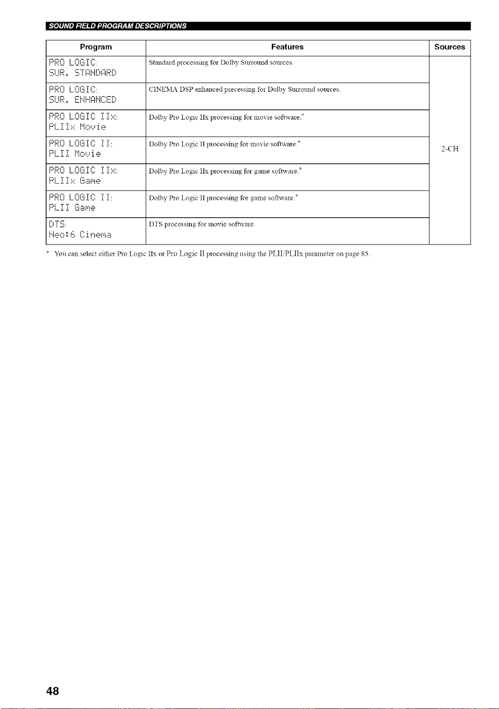
Program Features Sources
i::d:::,l"l..............i t"l ¢:.':j.TI"'. Stalldald processing fol Dolby SlU 10lllld SOlllCes
...._,...q'.. :: ...., _ i"_ 'H.."r'_F'._.."
i::d:::'l"=..............i _".':::a.'r _"'. CINEIVlA DSP enhallced plecessin_ foi Dolbv_ Surround sources.
,...i H..., _...i..n..a_ il..ii u.._ ',
i:::d:::,t"t i I"u':.':TI"' T T*. - • *
•. ............ a...... ..... Dolby PIo Logic IIx processing to] movte sofiwaie.
PL]:]:X M,:::,'...':i.e
i:::,i:::,t"l i F'H':::TF" T T
..............•............. ..,...... ... Dolby P*o Logic II processing fo_movie softwale * 2-CH
i,._i i i r,'h"ti,.i "Ig:,
i::d:::,t"= i I-==':::TI-' T T*. - *
•,.................. . ..... .... Dolby Pw Logic IIx processing tot game softwaie.
i:::,i T T. * l'::i.::ar,'H:::,
i L. ,i, ,,, ,,,.
iDi:::,F'l i F'H':::TI"' T T
•............. ..,...... ..... Dolby Pw Logic II processing fo_game sofiwae.*
i::d T T n.:::H'¢ll:::,
i i,,,* ,i, a..............
i",..,"i" ,:::'..... DTS p]ocessing 1_! movie softwaie.
_'ou can se]ect eitl]e] Pio Logic IIx o2 Pro l_ogic II p]ocessing using the PLII PLIIx paramete] on page 85.
48
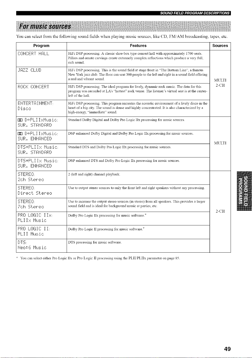
-'Io]#hV_l_l=lm_J'.t:[oI_t:Y-qJ_ll_]_;-'I_l:tl'.li[oJ_
You can select fi'om the following sound fields when playing music sources, like CD, FMAM broadcasting, tapes, etc.
Program Features Sources
"=l"fi..h"=ii:'C,"i"L.il"fii HiFi DSP processing. A classic shoe-box type co!lcelt hall with approximately 1700 seats.
Pillars and ornate cravings create extremely complex *eflections which produce a very fin
rich sound
T_","::'"::= _".i i i_::, HiFi DSP processing. This is tile sound field at stage front in "The Bottom Line", a t:amous
New York jazz club The floor can seat 300 people to the left and *ight in a sound field offe, ing
a real and vibrant sound MULTI
,.,*...,,....v,i::'_"'"'ii*....,...,_"'"_i"i_"'i:::'i::'"r'.,,,...._....v,_ HiFi DSP processing. The ideal prog*am tbr lively dynamic rock music The data fol this 2-CH
program was *ecorded at LA's "hottest" rock venue The listener's vi_tual seat is at the cente*-
le_ of tile hall.
i:ri,,i"L"i:rii::,"i"i='l,,".,.......TM h'ii::r M "i" HiFi DSP processing. This program recreates the acoustic environment of a lively disco in the
i'?'i.:::,"._", hemt of a big city The sotmd is dense and highly concentrated It is also characte*ized by a
high-energy "immediate" sound
rlrl {.)+ I' L J. ].I.::PIbi:ilHkC: Standa*d Dolby Digital and Dolby P*o Logic 11xprocessing tbr music sources
,:::"i ii:::, *:::'"i" 1%M r'., 1%i:::,1".,
....,*.,,q'.. :: .2 _ r".q 'H,,,'r".q',,L,
rlrl [)..I..F::'L]i ]ii.::{"ii...i:ill.:i,C : DSP enhanced Dolby Digital and Dolby Pro Logic Itx processing for music sources.
,:;_i lid i:::'Mi,,M"lMl==i::'r ',
....i*,,,q',, :: L,H _I ir"H ,p,,:L,,L,,
MULTI
L?I'.:::,"k}"L .[ .[ 1.:: ["{i...i'iil.:kC: Standard DTS and Dolby P*o Logic Itx processing t_! music sources
,::=i ii:::, *:::'"i"i='lM r'.,iu'lE:,] ".,
[)T'.!!.;..ki::'Li[]i1.:: Mi...i.lll.:i.c: DSP enhanced DTS and Dolby P*o Logic Itx processing to, music sou*ces
'::_iii:;?.. g'i'._i..4';::Ib.il":g'[':,
'.:::,I I:::.I"::U...'. 2 (lef_ and *ight) channel playback
::;!:,:::.i,S_:..ei."eo
' .........................'::_Ti::ri:;?l:::'l'' ' Use to output ste*eo sources to only the fiont left and right speake*s without any processing.
I71i.%::a_".1'.'.:::,1:.._iilq"'eO
...., II...I.,:'I...1' Use to increase the output stereo sources (in ste*eo) from all speakers This provides a large*
'?_".h c::'L,::ai."._:::,_", sound field and is ideal fm background music at parties etc
2-CH
J:::,i:::,,'°_i _",,':::'r_".'r 'r.,
.............. a...... .... .. Dolby Pro Logic ttx processing _bzmusic software *
i:::q 'r 'r, . ["{i a,:::. 'i _=',
, L,, ,i. ,. z,,
i::,i:::,¢"_ i _"H':::'r_", T T • - *
............. .a..... ..... Dolby Pro Logm 1Iprocessing foz musm sottwa*e
r""r":::'........ DTS processing for music so_ware.
l"4eO116 MiJ_::.'i ,",
• You can select eithe* Pro Logic 11xor Pro Logic II processing using the PLII PLIIx parameter on page 85.
49
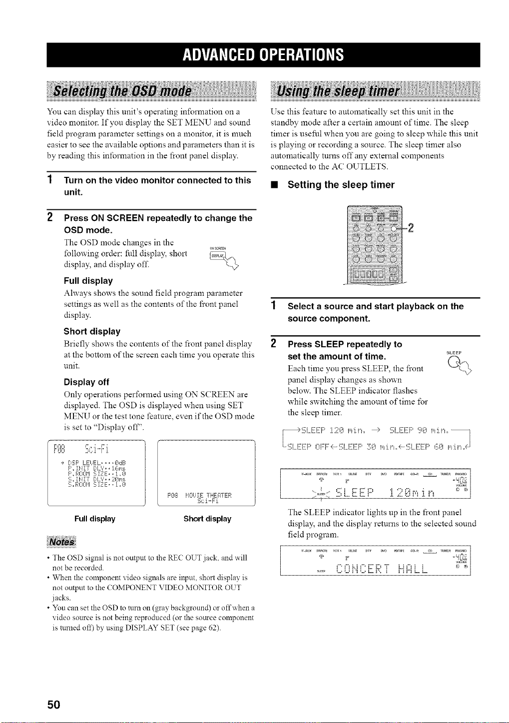
You can display this unit's operating information on a
video monitor. If you display the SET MENU and sound
field program parameter settings on a monitor, it is much
easier to see the available options and parameters than it is
by reading this information in the front panel display.
1 Turn on the video monitor connected to this
unit.
2 Press ON SCREEN repeatedly to change the
OSD mode.
The OSD mode changes in the
_NSCaEEN
following order: fi41 display, short _,___
display, and display off
L@
Full display
Ahvays shows the sound field program parameter
settings as well as the contents of the front panel
display.
Short display
Briefly shows the contents of" the front panel display
at the bottom of tlle screen each time you operate this
unit.
Display off
Only operations performed using ON SCREEN are
displayed. The OSD is displayed when using SET
MENU or the test tone feature, even if the OSD mode
is set to "Display off'.
r,@=I <%.;,o;:r;
r_'< .,=<q ii
÷ DS;P LEUEL, ,, ,[_dE:
F',,i}/!7 DL'?,, 1@:_
F',, RCIOM S iZ E,, 1 ,, 0
S,, IH! "r DL_',, 20_,_
S_RO@I SIZE,, i _0
_q-_ij_ 7. E¸- -r.,
F'@8 ,/.., _E , H:.,qTh....
2,_21"-b l
Full display Short display
• The OSD signal is not output to the RE(? OUT jack, and will
not be recorded.
• When the component video signals are input, short display is
not output to the COMPONENT \ffDEO MONITOR OUT
jacks.
• Yon can set the OSD to turn on (gray background) or offwhen a
video source is not being reproduced (or the source component
is turned off) by using DISPLAY SET (see page 62).
Use this feature to automatically set this unit in the
standby mode after a certain amount of time. The sleep
timer is useful when you are going to sleep while this unit
is playing or recording a source. The sleep timer also
automatically turns off any external components
connected to the AC OUTLETS.
• Setting the sleep timer
-2
1 Select a source and start playback on the
source component.
2 Press SLEEP repeatedly to
SLEEP
set the amount of time. f-h..
Each time you press SLEEP, the front
panel display changes as shown
below. The SLEEP indicator flashes
while switching the amount of time for
the sleep timer.
' _o([ 2) L,,i:::.i:::,r" [ ..(i,qrq [ iq
The SLEEP indicator lights up in the front panel
display, and the display returns to the selected sound
field program.
-frO;
g. __M g' i:7D "i" L,if"_i i _
50
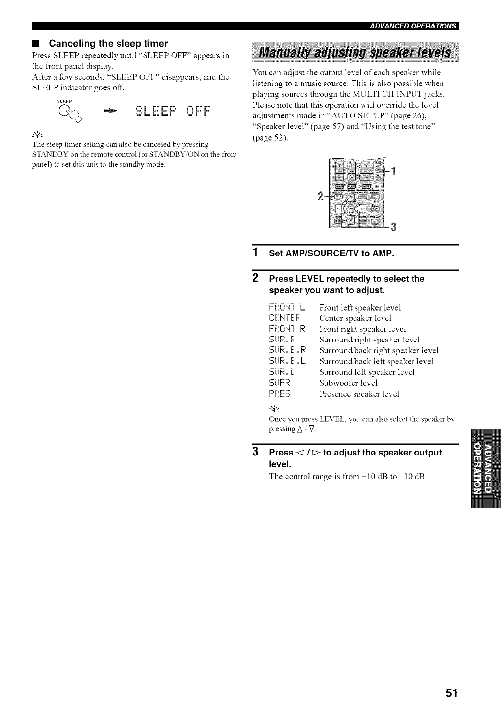
• Canceling the sleep timer
Press SLEEP repeatedly until "SLEEP OFF" appears in
the front panel display.
After a few seconds, "SLEEP OFF" disappears, and the
SLEEP indicator goes off.
SLEEP
•_J L, L. L. m B.Bm m
The sleep timer setting can also be canceled by pressing
STANDBY on the remote control (or STANDBY ON on the front
panel) to set this unit to the standby mode.
:y_Jr/_qt_[e,l:/_lel'.1:/:V__W#lel,_
You can adjust the output level of each speaker while
listening to a music source. This is also possible when
playing sources through the MULTI CH INPUT jacks.
Please note that this operation will oven'ide the level
adjustments made in "AUTO SETUP" (page 26),
"Speaker level" (page 57) and "Using the test tone"
(page 52).
E
1 SetAMP/SOURCEKVtoAMP.
2
Press LEVEL repeatedly to select the
speaker you want to adjust.
12:_:::,='=li..i "i " i
i l',,,,,.q'.,l 1
n"*i:::'i.. r 'i" i:::'i:::,
n..._...,n H.._ n n...,
....,_...q r=.:: I".
'... H n... n..._
iii_i:ii_iii:'_ii:*
_.,&
Once you press
pressing Z_g
Front left speaker level
Center speaker level
Front right speaker level
Surround right speaker level
Surround back right speaker level
Surround back left speaker level
Surround left speaker level
Subwoofer level
Presence speaker level
LEVEL, you can also select the speaker by
Press <1 / c> to adjust the speaker output
level.
The control range is from +10 dB to 10 dB.
51
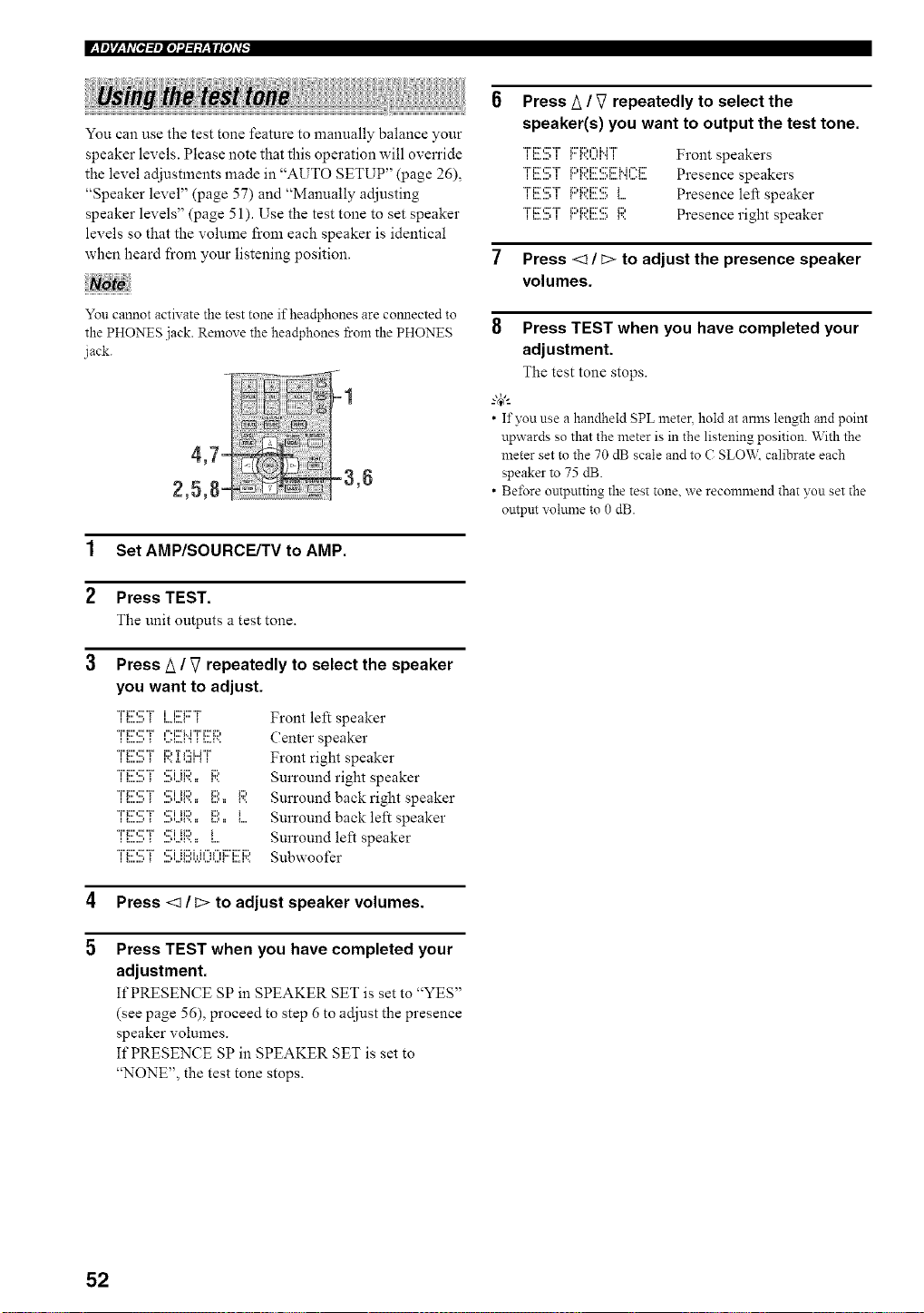
You can use the test tone feature to manually balance your
speaker levels. Please note that this operation will override
the level adjustments made in "AUTO SETUP" (page 26),
"Speaker level" (page 57) and "Manually adjusting
speaker levels" (page 51). Use the test tone to set speaker
levels so that the volume from each speaker is identical
when heard from your listening position.
You cannot activate the test tone if headphones are comlected to
the PHONES jack. Remove the headphones from the PHONES
jack.
1 Set AMP/SOURCE/TV to AMP.
2 Press TEST.
The unit outputs a test tone.
3 Press/_ / V repeatedly to select the speaker
you want to adjust.
"i"ii::',::2"i" ,:2i ii:::, i1::,
"i"ii::',::2"i" ,:2i ii:::, i:::, i:::,
*'H:::":::;"i"'::;iii:;).. P,.. i
"i"ii::',::2"i" ,:2i ii:::, i
i i... ,... t ,... i ll...,i, i i ii i i... i... i..J
Front left speaker
(:enter speaker
Front right speaker
Surround right speaker
Surround back right speaker
Surround back left speaker
Surround left speaker
Subwoofer
4 Press <1 / D to adjust speaker volumes.
5
Press TEST when you have completed your
adjustment.
It'PRESENCE SP in SPEAKER SET is set to "YES"
(see page 56), proceed to step 6 to adjust the presence
speaker volumes.
If PRESENCE SP in SPEAKER SET is set to
"NONE", the test tone stops.
Press A / _7 repeatedly to select the
speaker(s) you want to output the test tone.
*'i"i::_',:::'*'i"ii.._...., i _i:::'_i::'t"H"r'i"_...,...H".,i Front speakers
"J"J::r,::rT_:::,_:::,J::r,::rm..J,-._::'Presence speakers
TJ::r,:::T _:::,_::,J:::,:::_ Presence left speaker
*'J"J:r,::r*'J"_:::,_:::,J:::,:::_:::, Presence right speaker
7 Press <1/C> to adjust the presence speaker
volumes.
8 Press TEST when you have completed your
adjustment.
The test tone stops.
--'4_'--
• If you use a handheld SPL metec hold at arms length and point
upwards so that the meter is in the listening position. With the
meter set to the 70 dB scale and to C SLO'V_,:calibrate each
speaker to 75 dB.
• Before ontpntting the test tone. we recommend that you set the
ontpm volume to 0 dB.
52
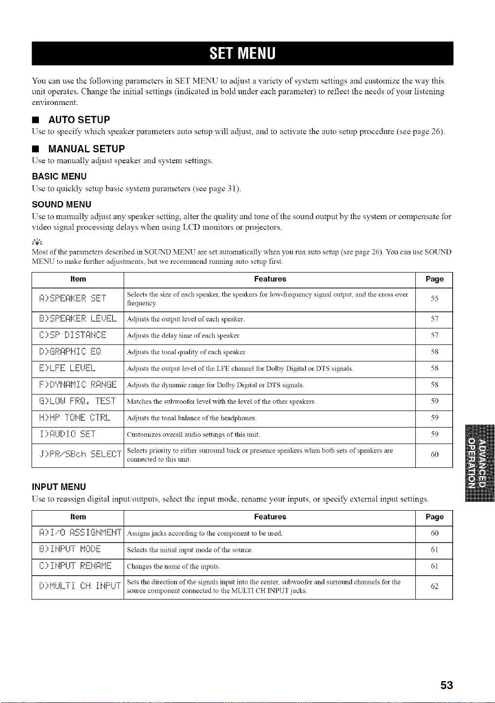
You can use the following parameters in SET MENU to adjust a variety of system settings and customize the way this
unit operates. Change the initial settings (indicated in bold under each parameter) to reflect the needs of your listening
environment.
• AUTO SETUP
Use to specify which speaker parameters auto setup will adjust, and to activate the auto setup procedure (see page 26).
• MANUAL SETUP
Use to manually adjust speaker and system settings.
BASIC MENU
Use to quickly setup basic system parameters (see page 3 i).
SOUND MENU
Use to manually adjust any speaker setting, alter the quality and tone of the sound output by the system or compensate for
video signal processing delays when using LCD monitors or proiectors.
g4_'--
Most of the parmneters described in SOUND MEN]I are set automatically when you run auto setup (see page 26). You can use SOI__rND
MENU to make further ac[iustments, but we recommend rtmning auto setup first.
Item Features Page
I"l"_I:L"i:li:'l"li..='i::i:l_:'i::'"i" Selects tile size of each speakei tile speakels tor Iow-fleqllency signal olltptlt, and tile cross ovei
iiiil i.. iiill iiiiiiii_ii.,iiiii_iii ,iiiiiii,= _ 55
fiequency
i:::,", ,:::'i:::,i:::'l"HY_::'i:::,i i::i ii:::'i Adjllsts the olltptlt level of each speaker. 57iiiili.'iii.ll iiiiiiii_ii,,iiiiiiiii iiiiiiii,=ii,,'iiiiiii
,"'",,:::'i:::,r'.,T,:'"r i",Mi"i::: Adjusts the delay tinle of each speaker 57_iiiI i., iiill iii=" iii ,iii I i iii_l iilii= 1....
InII." Iii.l111i_nIHi"l " 1':5i:::l l"l i:::' i"i 'rI"'i1 .i. ,.... iiiii ii:=:i:::' i-i Adjusts the tonal quality of each speakei 58
_.......,...._i:::''.,i i:::'i:::'_.....,...._.........,...._ii:::'iii:::i Adjusts the output level of the LFE channel fo! Dolby Digital or DTS signals 58
,......",....I.,,..,MI,_.,r".,,'l"_.,.I,....'' _'..r".,,""l...m.:,.....,,........ Adjusts the dynamic range for Dolby Digital oi DTS signals. 58
,':::".,i ,"li.i i:::'i:::,l'_"ri:r¢:'T'
,...,..",....,...,,.v_ _'..,.:.:=, _,..._...,, Matches the subwoofer level with tile level of tile othei speakeis 59
_ _ r" _ _i...i ", i...ii: I "i"l"lMi:::_ '.iil_ Illii.= '...' _ml.+"'"i%:)i Adjusts the tonal balance of the headphones 59
1]11"]"_'...l[.."1[.Ii..i....i]....] Customizes overall audio settings of this unit. 59
j' ) F:,R/,.!!;I:::h....I.=_,:::'ixrii:::,=="rSelects priori b, to either surround back or presence speakeis when both sets of speakers aie
.........,.......=_ 60
connected to this unit
INPUT MENU
Use to reassign digital input outputs, select the input mode, rename your inputs, or specify external input settings.
Item Features Page
I"I ,"I"l "_ T.I.,." I=llii.I I"_ ,,,*l ,,,,I ,L I,,,l I _ 1I"l I::'%:::' T I'::: i" i i'l'i i:::' H "i_I I....I _ _ Assigns jacks according to the conll3onent to be llsed. _0
i!!)):[i"ii:::'UT MIX:'E Selects tile initial input mode of the source 61
{ . .i _ {111111111 I t I11.1111. {1111 {11_{111
'iiii i." i[* I II_ Iii*' _ lI..lii.=l ',".'_ _ .... ChaIlges the name of the i!lplltS _1
i::,)MLiL.T]: UH ]:I"4F:'i...iTSetsthedirecti_n_fthesigna_sinputint_thecente_,subw_fe_andsm`_undchanne_sf_rthe 62
source component connected to tile MULTI CH INPUT jacks
53
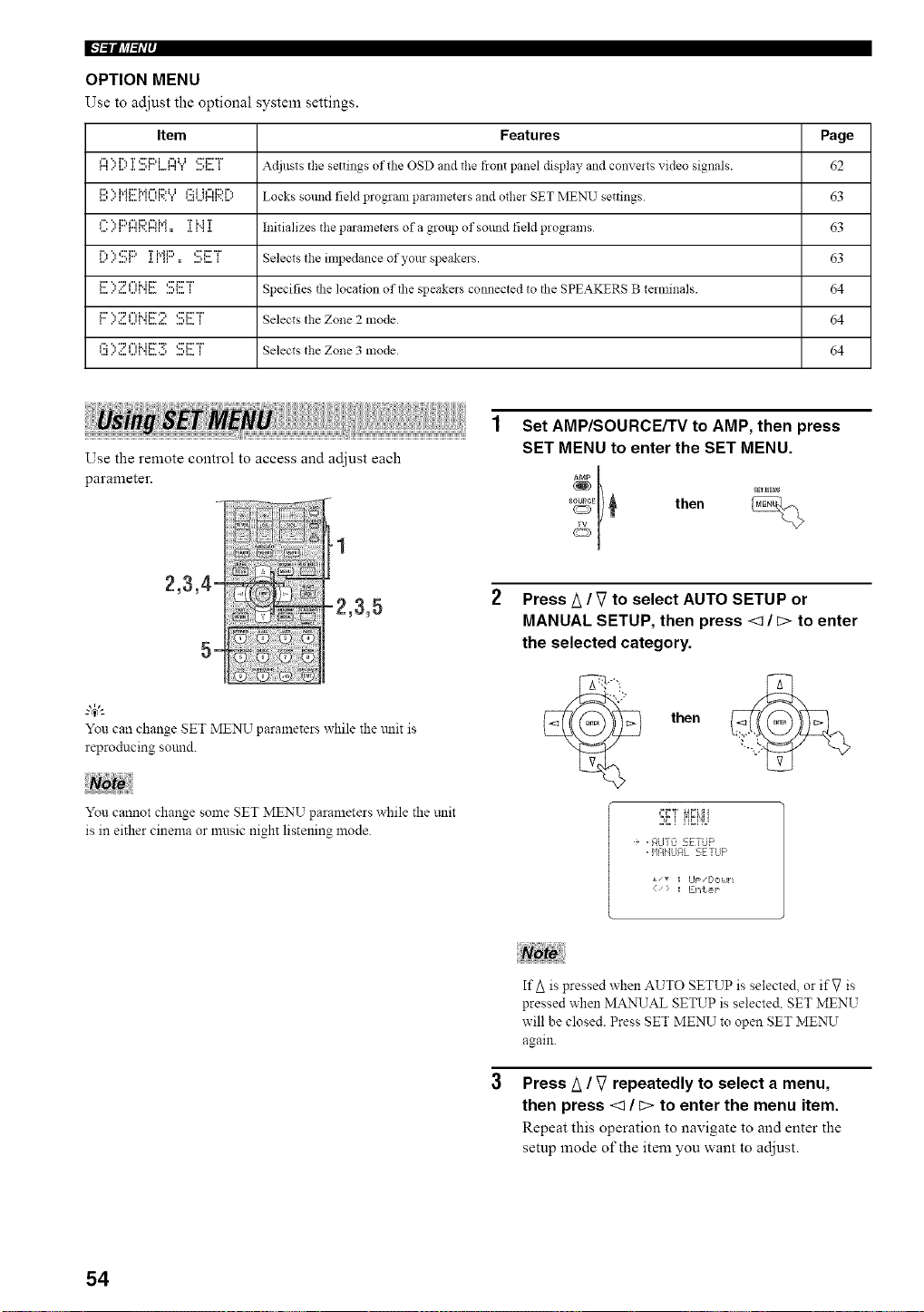
IN=ilfl?l_i'l'
OPTION MENU
Use to adjust the optional system settings.
Item Features Page
r"II"t",...l....r"*.I.T...,i*::'EML. r"li"tUI ....q....':::'i:::'"i"_ Adjllsts the settings of die OSD and the front panel display and convelts video signals. 62
i:::, ", i',Ji:::'?,'i¢"d:::,U ¢:_i h"d:::,i%
,...,..', ,,....,,,...,,'.., ,..,,...,r",,'..,.. Locks sound field program parameters and other SET MENU settings 63
_"' ", i:::q"li:::,¢"d',J T M T
*.....',r",,'..,",,,, ._.,".,.,. Initializes the parameters of a group of sound field programs 63
l:::'::':!!;l:::']:i'q:::'.:!!!;E:T Selects the impedanceofyourspeakers. 63
,......',:...u_',,.......,_...._ Specifies the location of the speakers connected to the SPEAKERS B terminals. 64
i:::' ", "2 _"li..ii::F ") _:::'i::F"i"
, ...,:...*...,_.,,...._.....,,..._ Selects the Zone 2 mode 64
l'::i................................":'::::'l"li".JFr:'::;c:IF"[ Selects the Zone 3 mode 64
Use the remote control to access and adjust each
parameter.
g4)l-
You can change SET MENU parameters while the trait is
reproducing sound.
You cannot change some SET MENU parameters while the trait
is in either cinema or music night listening 1node.
Set AMP/SOURCE/TV to AMP, then press
SET MENU to enter the SET MENU.
s_E_ then
Press A /V to select AUTO SETUP or
MANUAL SETUP, then press <1 / c> to enter
the selected category.
then
i, .¢!JT:Z 5ETiJF'
• q!qNLJAL SETUP
{) _ Ent,s,p
If A is pressed when AUTO SETUP is selected, or if V is
pressed when MANUAL SETUP is selected. SET MENU
will be closed. Press SET MENU to open SET MENU
again.
Press A / V repeatedly to select a menu,
then press <1 / c> to enter the menu item.
Repeat this operation to navigate to and enter the
setup :node of the item you want to adjust.
54
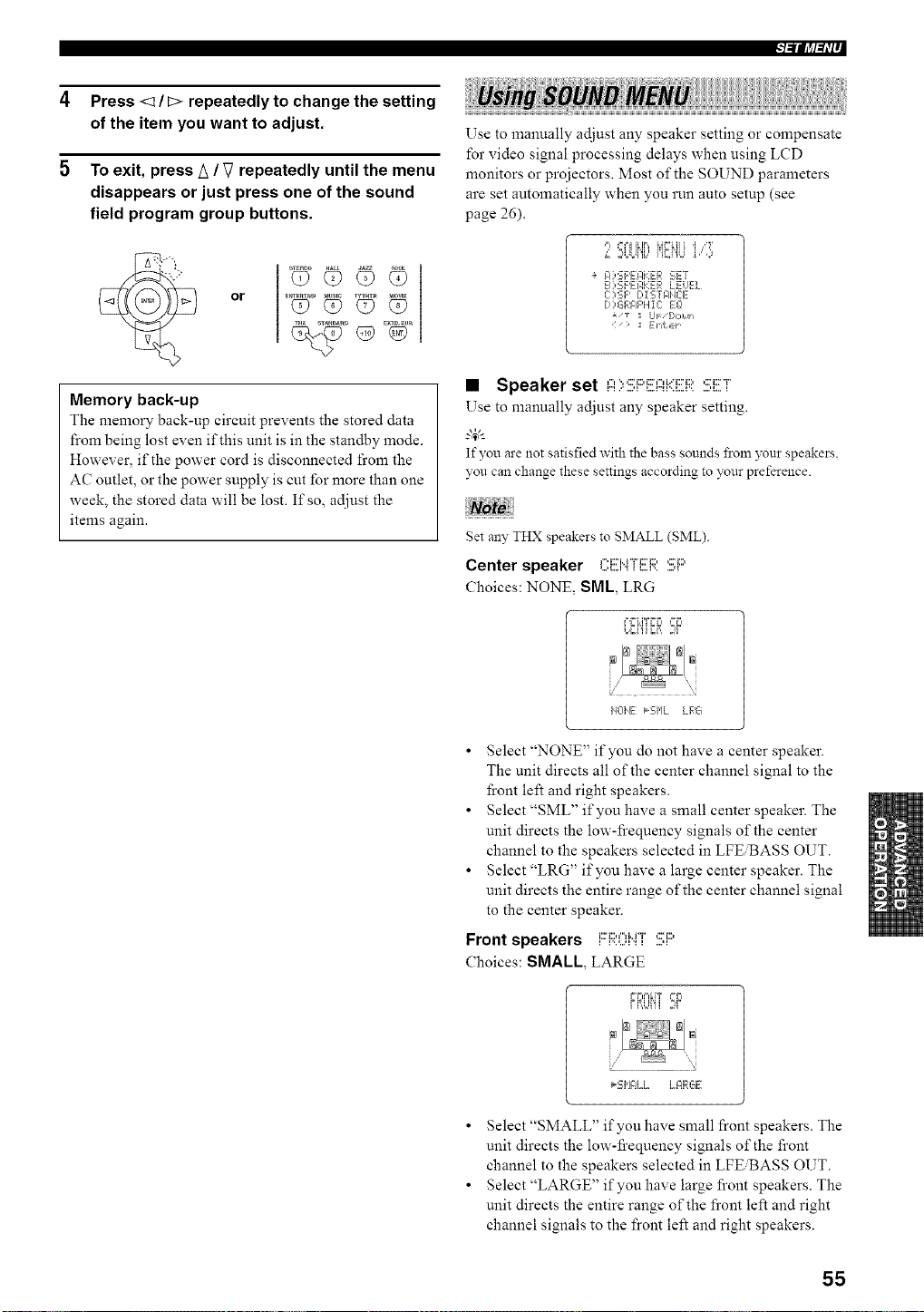
l_lllJ,tl_li--
4 Press <1 / C> repeatedly to change the setting
of the item you want to adjust.
5 To exit, press A / V repeatedly until the menu
disappears or just press one of the sound
field program group buttons.
or
D E×TD_SUR
Memory back-up
The memory back-up circuit prevents the stored data
from being lost even if this unit is in the standby mode.
However, if the power cord is disconnected fi'om the
AC outlet, or the power supply is cut for more than one
week, the stored data will be lost. If so, adjust the
items again.
Use to manually adjust any speaker setting or compensate
for video signal processing delays when using LCD
monitors or projectors. Most of the SOUND parameters
are set automatically when you run auto setup (see
page 26).
,==EFI ILIF,,k,}F'ki]i i_ ir41b=It
L ,;,UJi'ib' i'U",i"iU i," ,,)
A ) SF'EI:IHER SEr
B 2_;F'EI:,KER LELEL
C:?SF' [,i'_iTFI'E E
D)GFJ:IF'H1C: EO
_/_ UF [,,2,Ull
> := gilt,,,
• Speaker set I:::I):!;i:::'EI::?i.(ER:!!!;i!!!;r
Use to manually adjust any speaker setting.
g&
If you are not satisfied with the bass sounds from 3_ur speakers.
you can change these settings according to your preference.
get an?, THX speakers to SMALL (SML).
Center speaker ,".:'u"r_::D ,:::'_::,
Choices: NONE, SML, LRG
F,FLITFF_ _=F_
L,Ci'iiii, ,W
i40IE k'-_' Jw, h. LRG
• Select "NONE" if you do not have a center speaker.
The unit directs all of the center channel signal to the
front left and right speakers.
• Select "SML" if you have a small center speaker. The
unit directs the low-fi'equency signals of the center
channel to the speakers selected in LFE'BASS OUT.
• Select "LRG" if you have a large center speaker. The
unit directs the entire range of the center channel signal
to the center speaker.
Front speakers FR0i"4T :!!;i::'
Choices: SMALL, LARGE
FRUi'ii ,W
_:,IH .... LE4RGE
• Select "SMALL" if you have small front speakers. The
unit directs the low-fi'equency signals of the front
channel to the speakers selected in LFE_ASS OUT.
• Select "LARGE" if you have large front speakers. The
unit directs the entire range of the front left and right
channel signals to the front left and right speakers.
55
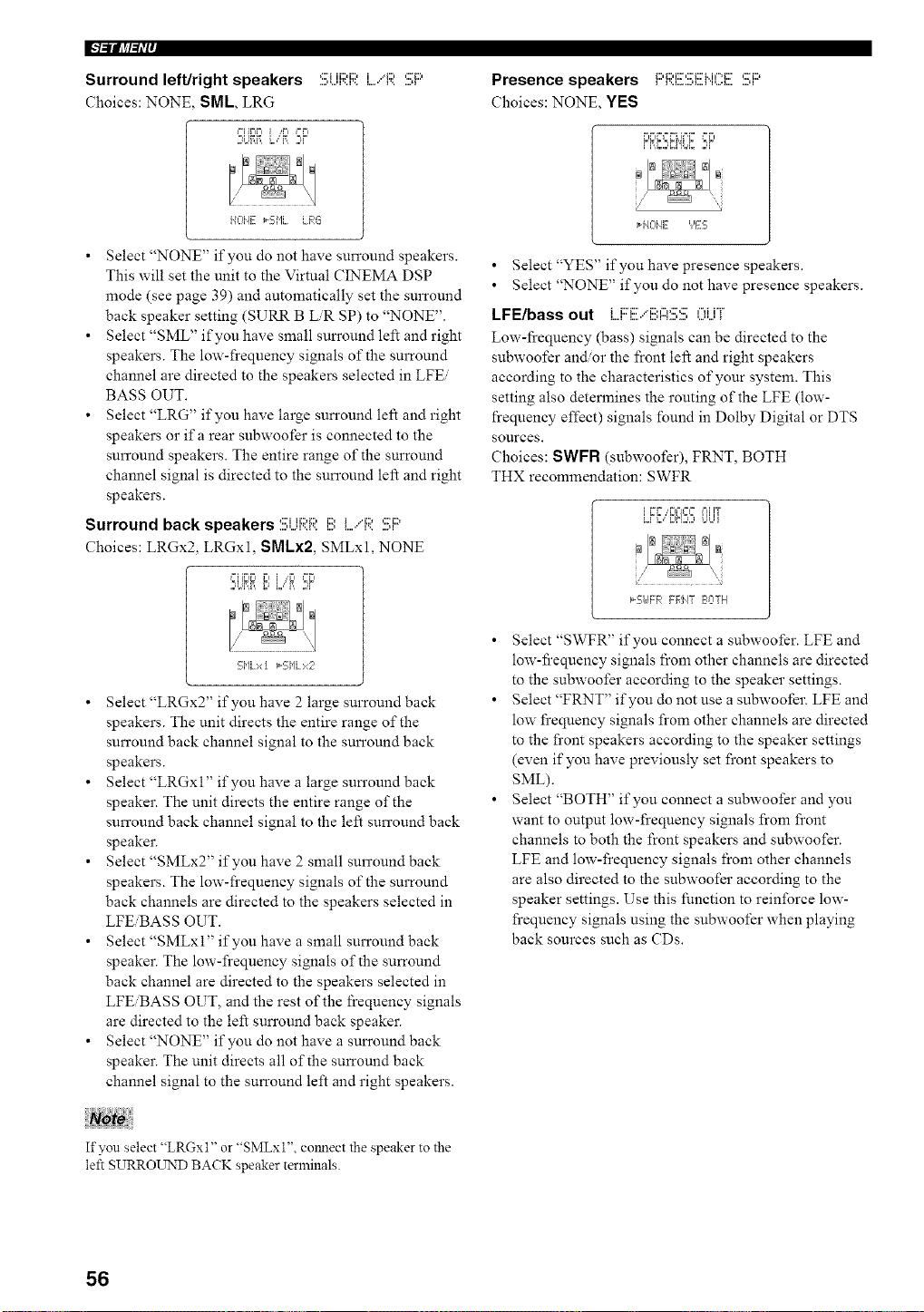
I"l=ii[J_l=li'i'
Surround left/right speakers
Choices: NONE, SML LRG
2U?,_L,"_ 2r
....,,...q'..l'.. l....' I'......q
HOI'4E _-S['IL LFqG
• Select "NONE" if you do not have surround speakers.
This will set the unit to the Virtual CINEMA DSP
mode (see page 39) and automatically set the surround
back speaker setting (SURR B LiR SP) to "NONE".
• Select "SML" if you have small surround left and right
speakers. The low-frequency signals of the surround
channel are directed to the speakers selected in LFEi
BASS OUT.
• Select "LRG" if you have large surround left and right
speakers or ifa rear subwoofer is connected to the
surround speakers. The entire range of the surround
channel signal is directed to the surround left and right
speakers.
Surround back speakers :!!!:UF;;:Ri!!) I..../F;;::!!;F::'
Choices: LRGx2. LRGxl, SMLx2, SMLxl, NONE
,o_ii[W.,r, _.,r, ,°r,
5i'lLxt _Si'lLx2
• Select "LRGx2" if you have 2 large surround back
speakers. The unit directs the entire range of the
surround back channel signal to the surround back
speakers.
• Select "LRGxl" if you have a large surround back
speaker. The unit directs the entire range of the
surround back channel signal to the left surround back
speaker.
• Select "SMLx2" if you have 2 small surround back
speakers. The low-frequency signals of the surround
back channels are directed to the speakers selected in
LFEiBASS OUT.
• Select "SMLxl" if you have a small surround back
speaker. The low-frequency signals of the surround
back channel are directed to the speakers selected in
LFEiBASS OUT, and the rest of the frequency signals
are directed to the left surround back speaker.
• Select "NONE" if you do not have a surround back
speaker. The unit directs all of the surround back
channel signal to the surround left and right speakers.
Presence speakers i;;,_1;,i;[',;?_1;'M¢==_1;' ,;?i;;)i D.L,-..'I.._'V..q......q
Choices: NONE, YES
H4014E ','ES
• Select "YES" if you have presence speakers.
• Select "NONE" if you do not have presence speakers.
LFE/bass out L.F::E.."i!!)A:!!!;!!!;OUT
Low-fi'equency (bass) signals can be directed to the
subwoofer and/or the front left and right speakers
according to the characteristics of your system. This
setting also determines the routing of the LFE (low-
frequency effect) signals found in Dolby Digital or DTS
sources.
Choices: SWFR (subwoofer), FRNT, BOTH
THX recommendation: SWFR
f
*5UFR FF,J4T Ea:ITH
• Select "SWFR" if you connect a subwoofer. LFE and
low-fi'equency signals from other channels are directed
to the subwoofer according to the speaker settings.
• Select "FRNT" if you do not use a subwoofer. LFE and
low frequency signals from other channels are directed
to the front speakers according to the speaker settings
(even if you have previously set front speakers to
SML).
• Select "BOTH" if you connect a subwoofer and you
want to output low-frequency signals from front
channels to both the front speakers and subwoofer.
LFE and low-frequency signals from other channels
are also directed to the subwoofer according to the
speaker settings. Use this function to reinforce low-
frequency signals using the subwoofer when playing
back sources such as CDs.
If you select "LRGxl" or "SMLxl", cmmect the speaker to the
left SURROUND BACK speaker terminals.
56
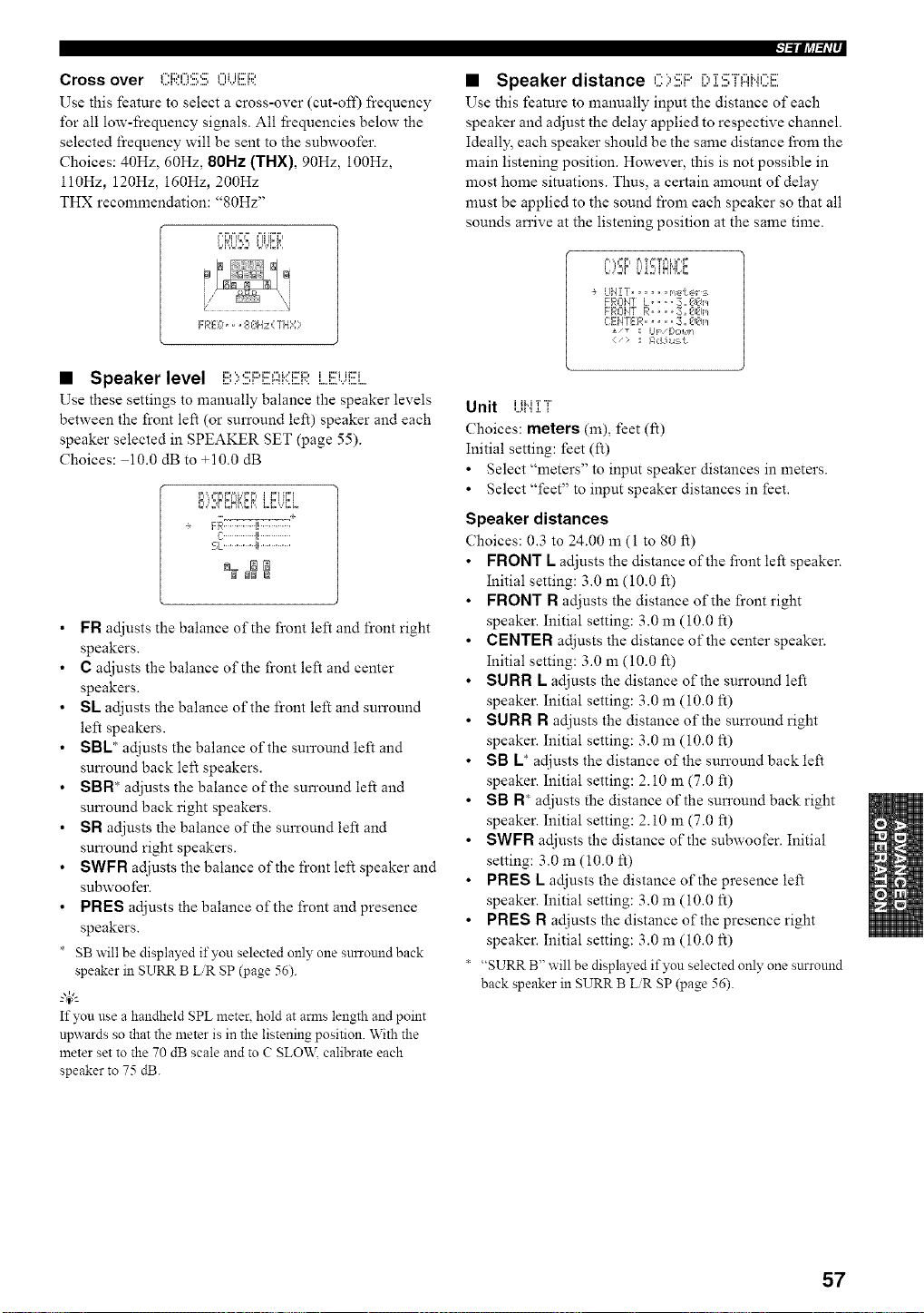
Cross over C:F;;:O:!!!;E;OUEF;;I
Use this feature to select a cross-over (cut-oil) l}equency
for all low-frequency signals. All frequencies below the
selected frequency will be sent to the subwoofer.
Choices: 40Hz, 60Hz, 80Hz (THX), 90Hz, 100Hz,
ll0Hz, 120Hz, 160Hz, 200Hz
THX recommendation: '_80Hz"
FREL:,,, 813Hz{ THY;
• Speaker level B::,:!!!;i:::i!![Ai.::]!![RLi!![UE]
Use these settings to manually balance the speaker levels
between the front left (or surround left) speaker and each
speaker selected in SPEAKER SET (page 55).
Choices: 10.0 dB to +10.0 dB
_l,,i ziL_J,,z _l i i,,,I ii,,,I
-__ .... +
FR............, .............
_,L...............!_...............
FR adjusts the balance of the front left and front right
speakers.
C adjusts the balance of the front left and center
speakers.
SL adjusts the balance of the front left and sun'ound
left speakers.
SBL* adjusts the balance of the surround left and
sun'ound back left speakers.
SBN* adjusts the balance of the surround left and
sun'ound back right speakers.
SN adjusts the balance of the surround left and
sun'ound right speakers.
SWFN adjusts the balance of the front left speaker and
subwoofer.
PNES adjusts the balance of the front and presence
speakers.
SB will be displayed if you selected only one snrround back
speaker in SURR B LiR SP (page 56).
4_"-
If you use a handheld SPL meter, hold at amls length and point
npwards so that the meter is in the listening position. With the
meter set to the 70 dB scale and to C SLO\_,_ calibrate each
speaker to 75 dB.
l=lllJ,tl_li--
• Speaker distance C::,:!!!;F::'[:' ]::!!;";rAH(.'.':E
Use this feature to manually input the distance of each
speaker and adjust the delay applied to respective channel.
Ideally_ each speaker should be the same distance from the
main listening position. However, this is not possible in
most home situations. Thus, a certain amount of delay
must be applied to the sound from each speaker so that all
sounds an'ive at the listening position at the same time.
p, ,, i=,== ,=,,,=i= ,====kip,,=,
bJ2¢ i.,'_2_iN'ibr.,
UiqZT .... meker:_
FROIqT L .... 3. #J€_m
FROiqT R .... :__ #l#Im
C:EIqTER.... _;., €1_5,/
LIF/[:,o14 =
> _I I:_,.i*umL
Unit UH ]:T
Choices: meters (m), feet (It)
Initial setting: feet (It)
• Select "meters" to input speaker distances in meters.
• Select "feet" to input speaker distances in feet.
Speaker distances
Choices: 0.3 to 24.00 m (I to 80 ft)
FRONT L adjusts the distance of the front left speaker.
Initial setting: 3.0 m (10.0 It)
FRONT N adjusts the distance of the front right
speaker. Initial setting: 3.0 m (10.0 It)
CENTER adjusts the distance of the center speaker.
Initial setting: 3.0 m (10.0 It)
SU N N K adjusts the distance of the sun'ound left
speaker. Initial setting: 3.0 m (10.0 It)
SU N N N adjusts the distance of the sun'ound right
speaker. Initial setting: 3.0 m (10.0 It)
SB K* adjusts the distance of the sun'ound back left
speaker. Initial setting: 2.10 m (7.0 ft)
SB N* adjusts the distance of the surround back right
speaker. Initial setting: 2.10 m (7.0 ft)
SWFN adjusts the distance of the subwoofer. Initial
setting: 3.0 m (10.0 It)
PNES L adjusts the distance of the presence left
speaker. Initial setting: 3.0 m (10.0 It)
PNES N adjusts the distance of the presence right
speaker. Initial setting: 3.0 m (10.0 It)
* "SURR B" will be displayed if you selected only one surround
back speaker in SURR B LiR gP (page 56).
57
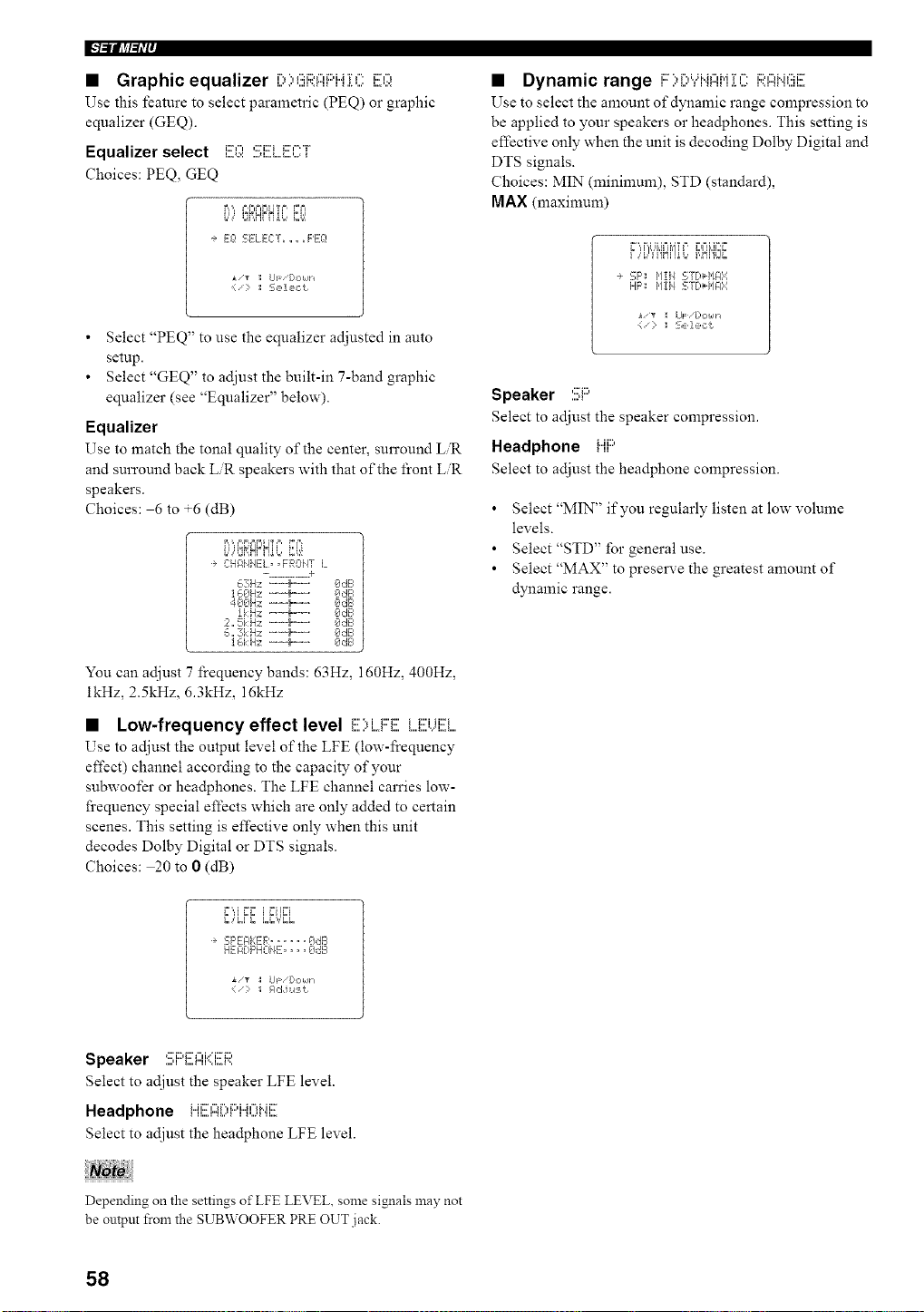
• Graphic equalizer r,,'.,,':::i:,,-,_:::,i..J'r,-,i::,-,
Use this feature to select parametric (PEQ) or graphic
equalizer (GEQ).
Equalizer select m..., ,:::i:::__:::',-'"_"L,A:': ,,,.H,,,A,,,,L,, ',,."
Choices: PEQ, GEQ
B,',, F,F.==FIITF , FF=
I.'; '_',_I_ II_'# 6'.',
-÷ Eg! SELECT ...... PEg!
][/_ ; UF [:l,:lklh
: S, ,1, ,,:t
• Select "PEQ" to use the equalizer adjusted in auto
setup.
• Select "GEQ" to adjust the built-in 7-band graphic
equalizer (see "Equalizer" below).
Equalizer
Use to match the tonal quality of the center, surround LR
and surround back LiR speakers with that of the front LiR
speakers.
Choices: 6 to +6 (dB)
i.L,q_RHnI_L,U,:,!
C:HAHHE:L, ,FROHT L
- ............ :e
63Hz _'--'-_....... I_:l,:_E,
400Hz -=_--=. OdE=
!kHz --m_---. OdB
2,, 5i:H;_ "--'-_ ....... OdB
_,,,3k Hz _-'-_+....... OdB
] _,i:Hz --_=---' OdE,
You can adjust 7 frequency bands: 63Hz, 160Hz, 400Hz,
ikHz, 2.5kHz, 6.3kHz, 16kHz
• Low-frequency effect level E)i..oFE M!{Ui!!!i....
Use to adjust the output level of the LFE (low-l_:equency
effect) channel according to the capacity of your
subwoofer or hea@hones. The LFE channel carries low-
frequency special effects which are only added to certain
scenes. This setting is effective only when this unit
decodes Dolby Digital or DTS signals.
Choices: 20 to 0 (dB)
F',,I ,'_F i FIIF=I
SF'EI:IEE:R...... OdB
HEFI[:,F'HOi4E.... Oc:B
• "_ :I UF/[:,C,k/-I
• Dynamic range i:::::,i:::,Yi"iI:::Ii"i:[Ci:;;:Ai".iEii!![
Use to select the amount of dynamic range compression to
be applied to your speakers or headphones. This setting is
effective only when the unit is decoding Dolby Digital and
DTS signals.
Choices: MIN (minimum), STD (standard),
MAX (maximum)
F)i,l'i'i'iNiq'L,i,Nl'irJi,
-* '_:F': _,lIi/ 'ST[*l,/l:l::i
HF'; 1'11i1 '_:Y[,_HA:4
I LIF: /[:,C,kll _
(': : S,,le,:t
Speaker ....,:::i:::,.
Select to adjust the speaker compression.
Headphone ......
Select to adjust the headphone compression.
• Select "MIN" if you regularly listen at low volume
levels.
• Select"STD" for general use.
• Select "MAX" to prese]we the greatest amount of
dynamic range.
Speaker :!!!;i:::'E:I:::Ii'(i!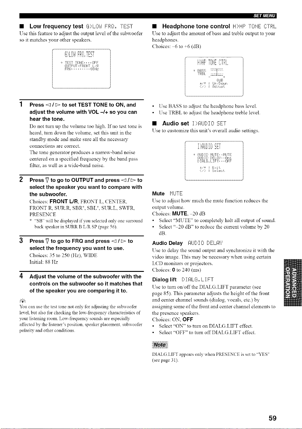
• Low frequency test ":::",i,...,i.__::._:::,,-,"H::>:::'"r_,,,i,." L,A,,",'._ I I',,',X • _ I,,..,,' I
Use this feature to adjust the output level of the subwoofer
so it matches your other speakers.
i_,"d l=li,i ;C,I==TD==T
_diMJL _ i i',J)i_iLJi
÷ rEST ICiHE .... OFF
OI TF'UT,FPOI4T LFI
l=llll,tl_li--
• Headphone tone control Li'.,i.Ji:::,"i%"lMC'i"'"H:::,i
Use to adjust the amount of bass and treble output to your
headphones.
Choices: 6 to +6 (dB)
÷ Bl?5:_; ........!!........
rF:BL :;.::,_.:_:::
OdB
r
Press <1 / c> to set TEST TONE to ON, and
adjust the volume with VOL -/+ so you can
hear the tone.
Do not turn up the volume too high. If no test tone is
heard, turn down the volume, set this unit in the
standby mode and make sure all the necessary
connections are correct.
The tone generator produces a narrow-band noise
centered on a specified I}equency by the band pass
filter, as well as a wide-band noise.
Press _7to go to OUTPUT and press <1 / c> to
select the speaker you want to compare with
the subwoofer.
Choices: FRONT I/R, FRONT L, CENTER,
FRONT R, SUR.R, SBR*, SBL*, SUR.L, SWFR,
PRESENCE
* "SB" will be displayed if you selected only one surround
back speaker in SURR B LiR SP (page 56).
Press V to go to FRQ and press <1 / c> to
select the frequency you want to use.
Choices: 35 to 250 (Hz), WIDE
Initial: 88 Hz
4 Adjust the volume of the subwoofer with the
controls on the subwoofer so it matches that
of the speaker you are comparing it to.
You can use the test tone not only for adjusting the snbwoot'er
level, but also t\_rcheckingthe fray-frequency characteristics of
your listening room. Low-frequency sounds are especially
affected by the listener's position, speaker placement, subwoofer
polarity and other conditions.
• Use BASS to adjust the headphone bass level.
• Use TRBL to adjust the headphone treble level.
• Audio set T'.,,".ir'.,'r,-,,:::i::"i"
,L ,."r".%,q,,,' ,I. ,,J ,,,..L. I
Use to customize this unit's overall audio settings.
,'HLJ{.,_kU 2,_i
i,q Tc¸
÷ F,tlr'!o ['ILITE .,1_ ,,.
GILIDiO[)Ekl:l',',, Om:k
[ [_4LG,,L !FT, _, L-]FF
:= Exit
Mute MUTE
Use to adjust how much the nmte function reduces the
output volume.
Choices: MUTE, 20 dB
• Select "MUTE" to completely halt all output of sound.
• Select " 20 dB" to reduce the current volume by 20
dB.
Audio Delay ALl[) :[ 0 [)ELI:::I"?
Use to delay the sound output and synchronize it with the
video image. This may be necessary when using certain
LCD monitors or projectors.
Choices: 0 to 240 (ms)
Dialog lift i) :[Ai....(!),,i....1:FT
Use to turn on/off the DIALG.LIFT parameter (see
page 85). This parameter adjusts the height of the front
and center channel sounds (dialog, vocals, etc.) by
assigning some of the front and center channel elements to
the presence speakers.
Choices: ON, OFF
• Select "ON" to turn on DIALG.LIFT effect.
• Select "OFF" to turn offDIALG.LIFT effect.
DIALG.LIFT appears only when PRESENCE is set to "YES"
(see page 31).
59
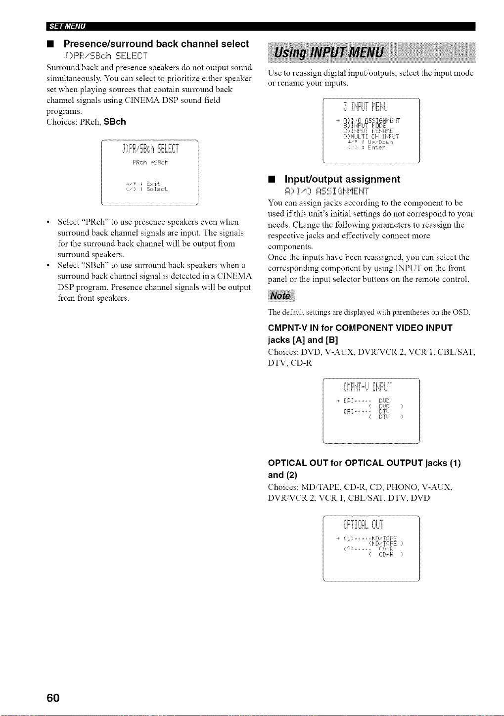
F'/-'llll_/'tl'i'
• Presence/surround back channel select
,:r::,F::i:;b.":!!!;Bch SE]....ECT
Sun'ound back and presence speakers do not output sound
sinmltaneously. You can select to prioritize either speaker
set when playing sources that contain sun'ound back
channel signals using CINEMA DSP sound field
programs.
Choices: PRch, SBch
F'Rci_ _-SB,::i _
• Select "PRch" to use presence speakers even when
surround back channel signals are input. The signals
for the surround back channel will be output from
surround speakers.
• Select "SBch" to use sun'ound back speakers when a
surround back channel signal is detected in a CINEMA
DSP program. Presence channel signals will be output
from fi'ont speakers.
Use to reassign digital input outputs, select the input mode
or rename your inputs.
ii'fi Ui i'ii',::i'9,_
A?iiO ASS IGiIME:iiT
B ? !NF'LITI'IODE
C::,iHF'UT REHAIIE
[>:q'IULTiC:H INPUT
> _: [:l_{?,r
• Input/output assignment
A>:[,"0 ASS]:EiHME:MT
You can assign jacks according to the component to be
used if this unit's initial settings do not correspond to your
needs. Change the following parameters to reassign the
respective jacks and effectively connect more
components.
Once the inputs have been reassigned, you can select the
con'esponding component by using INPUT on the front
panel or the input selector buttons on the remote control.
The default settings are displayed with parentheses on the OSD.
CMPNT-V IN for COMPONENT VIDEO INPUT
jacks [A] and [B]
Choices: DVD, V-AUX, DV_VCR 2. VCR 1, CBL SAT,
DTV, CD-R
r'l',iPi,iT4i 'r_H_'__"r
[A] .... f.!UD
DUD
[B] .... DTU
fYTU
OPTICAL OUT for OPTICAL OUTPUT jacks (1)
and (2)
Choices: MD TAPE, CD-R, CD, PHONO, V-AUX,
DVR.VCR 2, VCR 1, CBLiSAT, DTV, DVD
÷ (1) ..... MDiTAF'E
(HDiZAF'E ?
(2:> ..... c:r_-R
( C:D.-R :,
60
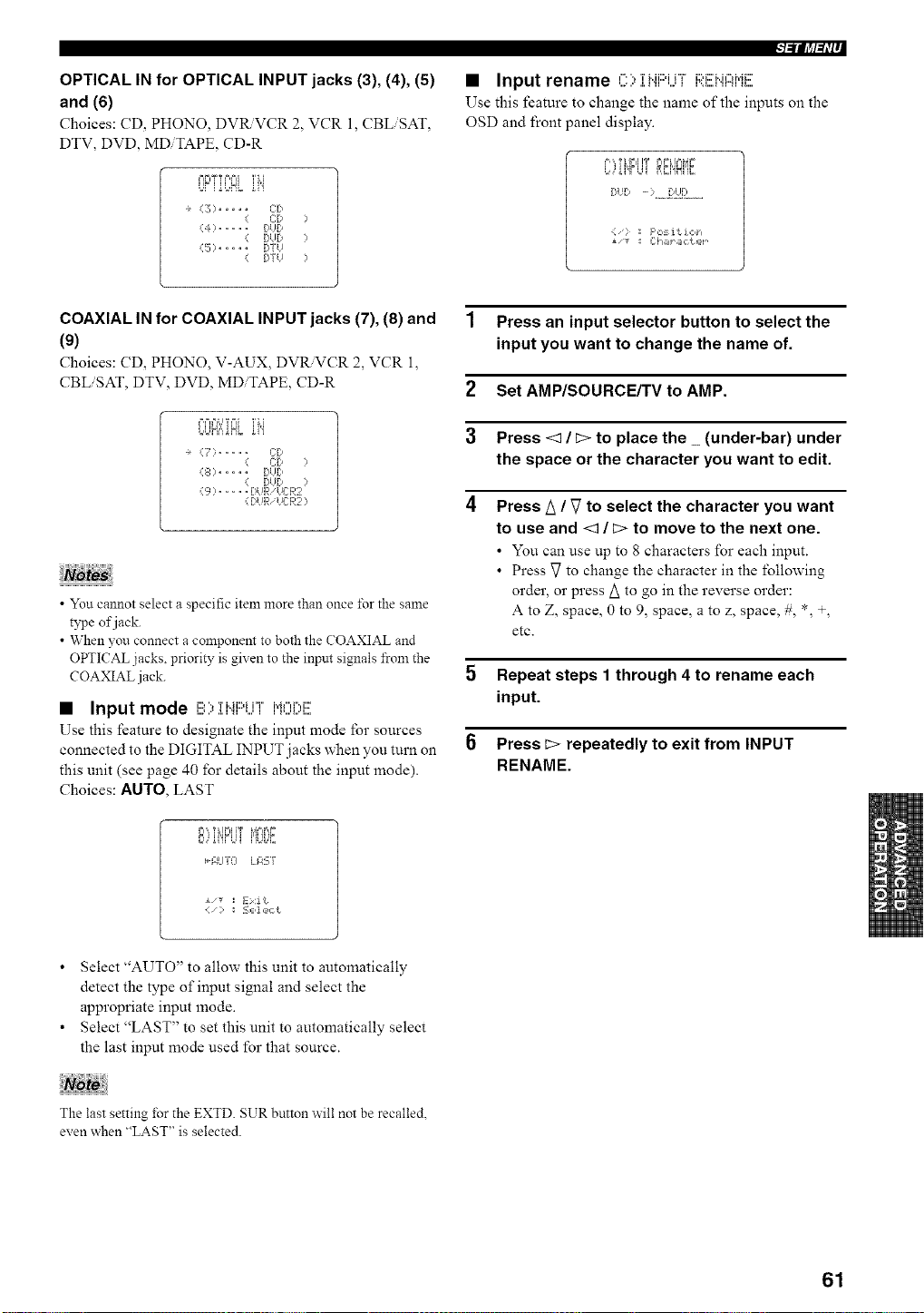
OPTICAL IN for OPTICAL INPUT jacks (3), (4), (5)
and (6)
Choices: CD, PHONO, DVRVCR 2, VCR l, CBLiSAT,
DTV, DVD, MDiTAPE, CD-R
MFiT T F,MI 'i' i, [
UFi iUNL ii"i
÷ (3) ..... CD
( C:P )
(4) ..... BUD
( DUD )
(5) ..... DYU
( [)TtJ )
l=ll?a_li--
• Input rename '-, 'rMi::)ir'F i::M:::'M,"H.di:::'
Use this feature to change the name of the inputs on the
OSD and front panel display.
F'",Tk',F=,i!T r,r_i,',_,_t
[:,HI, - ) ...iI[l_I......
F',:,:_i t ioh
±'_ _I Ch_r_lcter ¸
COAXIAL IN for COAXIAL INPUT jacks (7), (8) and
(9)
Choices: CD, PHONO, V-AUX, DVR.VCR 2, VCR l,
CBLiSAT, DTV, DVD, MDiTAPE, CD-R
F,F.%J TFA 'ri,[
L,L]HfiiNL gi"i
÷ (7) ..... CD
( C[> )
(.50 ..... DUg,
( [>I!D ?
{S) ..... DUR UL-:R2
( BUR 'UER2 )
• You cannot select a specific item more than once i\_r the same
type of jack.
• When you connect a component to both the COAXIAL and
OPTICAL jacks, priority is given to the inpnt signals from the
COAXIAL jack.
• Input mode i!!!Oiiqi:::'LiTi"i0i;,i!!!
Use this feature to designate the input mode lbr sources
connected to the DIGITAL INPUT jacks when you turn on
this unit (see page 40 for details about the input mode).
Choices: AUTO, LAST
Fi',, T i IFI I'F J,a,='=,=
iG_I'iFUII=io]L,_E
_£UTEI LIrP.--i[
i/* _l Exit
1 Press an input selector button to select the
input you want to change the name of.
2 Set AMP/SOURCE/TV to AMP.
3 Press <3 / _:>to place the _ (under-bar) under
the space or the character you want to edit.
4 Press A / _7to select the character you want
to use and <3 / _:>to move to the next one.
• You can use tip to 8 characters for each input.
• Press _7to change the character in the following
order, or press A to go in the reverse order:
A to Z, space, 0 to 9, space, a to z, space, #, *, +,
etc.
5 Repeat steps 1 through 4 to rename each
input.
Press _> repeatedly to exit from INPUT
RENAME.
• Select "AUTO" to allow this unit to automatically
detect the type of input signal and select the
appropriate input mode.
• Select "LAST" to set this unit to automatically select
the last input mode used for that source.
The last setting for the EXTD. SUR button will not be recalled.
even when "LAST" is selected.
61
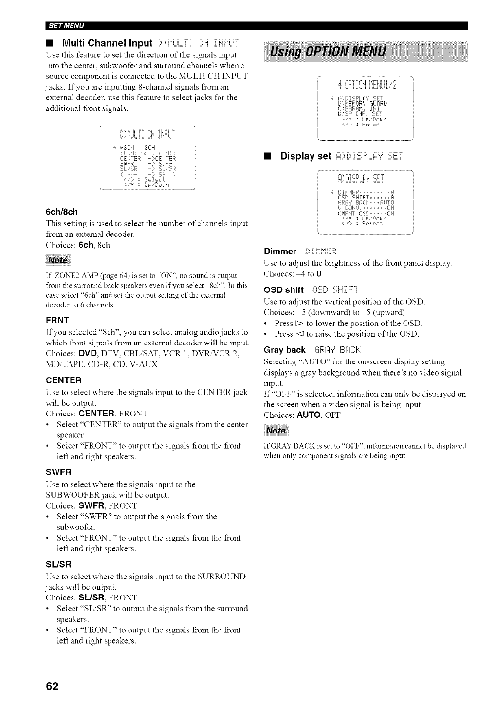
I["l=iifJ_l=li'l'
• Multi Channel Input D)HUi...,Fi OH ii".iF'UT
Use this feature to set the direction of the signals input
into the center, subwoofer and surround channels when a
source component is connected to the MULTI CH INPUT
jacks. If you are inputting 8-channel signals from an
external decoder, use this feature to select jacks for the
additional front signals.
i,i,@il]l i i l='_i T_jrIIIT
......... L,N"i'iFLq
_6C:H 8CH
(FRN7 'SB-? FRHT?
CENTER - ] C:EIITER
S[dFR -? S[dFR
SLSR SL'SR
( .......... ; 5E_ ?
:/: Sel ec<!
i'T tip '[_ONh
6ch/8ch
This setting is used to select the number of channels input
from an external decoder.
Choices: 6ch, 8eh
If ZONE2 AMP (page 64) is set to "ON", no sound is output
from the surround back speakers even if you select "8ch". In this
case select %ch" and set the output setting of the external
decoder to 6 chmmels.
FRNT
If you selected "8ch", you can select analog audio jacks to
which front signals from an external decoder will be input.
Choices: DVD, DTV, CBLiSAT, VCR 1, DVRVCR 2,
MDiTAPE, CD-R, CD, V-AUX
CENTER
Use to select where the signals input to the CENTER jack
will be output.
Choices: CENTER, FRONT
• Select "CENTER" to output the signals from the center
speaker.
• Select "FRONT" to output the signals fi'om the front
left and right speakers.
SWFR
Use to select where the signals input to the
SUBWOOFER jack will be output.
Choices: SWFR, FRONT
• Select "SWFR" to output the signals from the
subwoofer.
• Select "FRONT" to output the signals fi'om the front
left and right speakers.
SUSR
Use to select where the signals input to the SURROUND
jacks will be output.
Choices: SLJSR FRONT
• Select "SLiSR" to output the signals from the surround
speakers.
• Select "FRONT" to output the signals fi'om the front
left and right speakers.
,d P,_,T%%I MI%Hhl Ir'l_
ff Lli iUJi'i D2i'g,q,",_"o
_ ?B,i 5;F'LFI'? SET
BH IEIIOR? GLIglRD
C:?F',C,R,qI,L, IH1
D:,SF' IHF', SET
UF fH,,Mn
_i _htJ_4
• Display set "'i"i":::i:::'i ,,,, ,:::_:::r
_=,',,F,,TI=F=IPdl _=,"=T
f!,,'i.,"2_FLN'i' 2Bi
DI@IER ......... g
OSD 5;H!FT ...... _J
GF>-,',' EIPIZ}:>, ._ILITCI
g COf/U,,, ...... OH
C:lIF'i47 05;D ..... OH
i/v _I up I:,oklh
:= _ ::,sde,_t
Dimmer i...,T i',@,'ii='i2,
i...' .i. i ii II....D,
Use to adjust the brightness of the fi'ont panel display.
Choices: 4 to 0
OSD shift OSi) :!!!;Hii:::°i'
Use to adjust the vertical position of the OSD.
Choices: +5 (downward) to 5 (upward)
• Press E> to lower the position of the OSD.
• Press <1 to raise the position of the OSD.
Gray back GRI:::I'Y'[!!',l:::l(.'.':l'(
Selecting "AUTO" for the on-screen display setting
displays a gray background when there's no video signal
input.
If "OFF" is selected, information can only be displayed on
the screen when a video signal is being input.
Choices: AUTO, OFF
If GRAY BACK is set to "OFF", information cannot be displayed
when only component signals are being input.
62
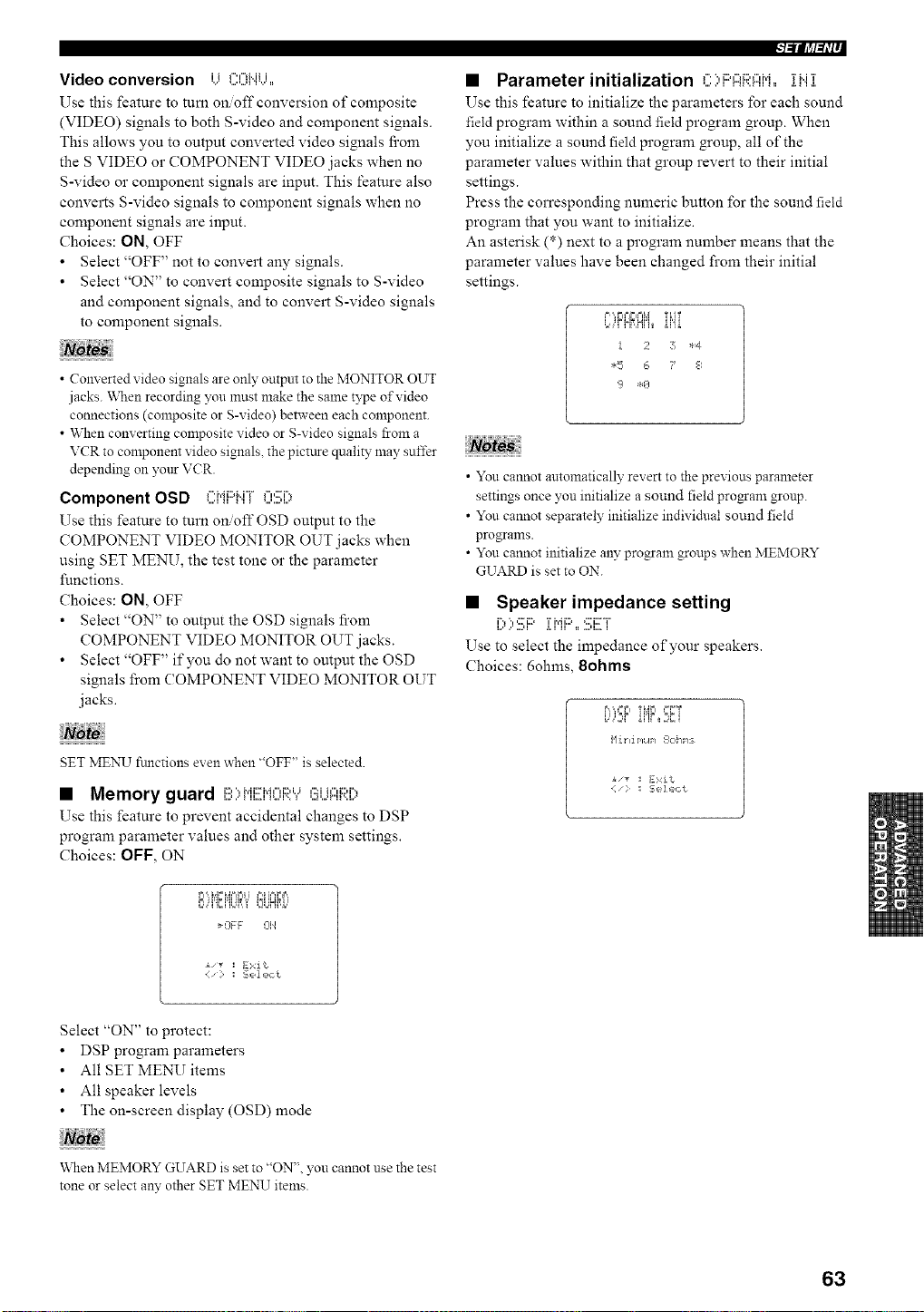
Video conversion i i f"u"lMii
%." _.,,,,,._i'1%,' •
Use this feature to turn on off conversion of composite
(VIDEO) signals to both S-video and component signals.
This allows you to output converted video signals fi'om
the S VIDEO or COMPONENT VIDEO jacks when no
S-video or component signals are input. This feature also
converts S-video signals to component signals when no
component signals are input.
Choices: ON, OFF
• Select "OFF" not to convert any signals.
• Select "ON" to convert composite signals to S-video
and component signals, and to convert S-video signals
to component signals.
• Converted video signals are only output to the MONITOR OUT
jacks. "When recording you must make the same type of video
connections (composite or g-video) between each component.
• When converting composite video or g-video signals from a
VCR to component video signals, the pictttre quality may suffer
depending on your VCR.
Component OSD CMF'MF OS[)
Use this feature to turn onoff OSD output to the
COMPONENT VIDEO MONITOR OUT jacks when
using SET MENU, the test tone or the parameter
functions.
Choices: ON, OFF
• Select "ON" to output the OSD signals fi'om
COMPONENT VIDEO MONITOR OUT jacks.
• Select "OFF" if you do not want to output the OSD
signals from COMPONENT VIDEO MONITOR OUT
jacks.
T
SET MENU fimctions even when "OFF" is selected.
• Memory guard I!!:){,{EIdC[I;['.Y(!_U{:::{[;i:[?
Use this feature to prevent accidental changes to DSP
program parameter values and other system settings.
Choices: OFF, ON
1 ,i i_n i_,,
¢,' ' L L,,,_2JHffi..'
_OFF 314
:I Exit
l-'illl_l-tli-
• Parameter initialization C;,i:::'ARFIiq,, il..i]:
Use this feature to initialize the parameters for each sound
field program within a sound field program group. When
you initialize a sound field progrmn group, all of the
parameter values within that group revert to their initial
settings.
Press the corresponding numeric button for the sound field
program that you want to initialize.
An asterisk (*) next to a program number means that the
parameter values have been changed from their initial
settings.
.,,,Ff!_,H,,_ ii'ii
! 2 7 *4
*F 6 ? 8
• You cannot automatically revert to the previous parameter
settings once you initialize a sound field progam group.
• You cannot separately initialize individual sound field
programs.
• You cannot initialize any program groups when MEMORY
GUARD is set to ON.
• Speaker impedance setting
l,x ,,' ,,,.*i .i. i ii _=..,u,,.. i
Use to select the impedance of'your speakers.
Choices: 6ohms, 8ohms
.'=,,',.=r,Ti_i;i '_T
Ni. t li PIL@/ 1_I1;'[ If'IS
• "_ :I E>,:it
Select "ON" to protect:
• DSP program parameters
• All SET MENU items
• All speaker levels
• The on-screen display (OSD) mode
\_qlen MEMORY GUARD is set to "ON", you cannot use the test
tone or select any other SET MENU items.
63
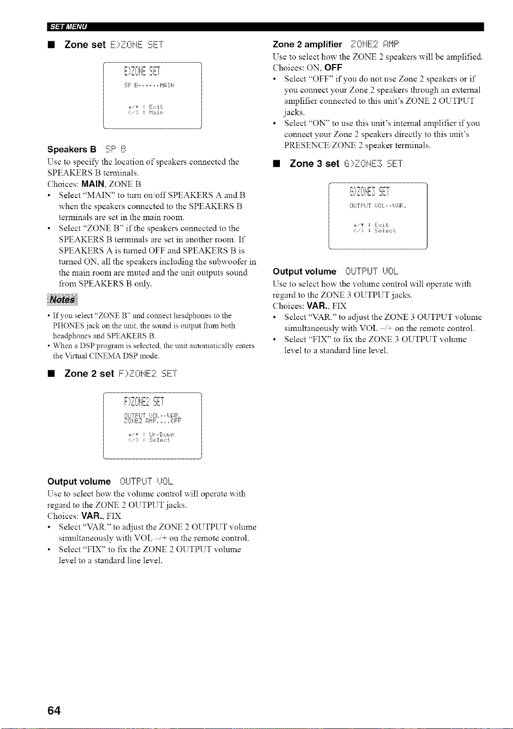
l"l=ii[_l=li'ff
• Zone set ':::"::"-'"'::,::'_::-T'
F ',."J F=[IF _=FT
i ,=,=LI'IC,;]Ci
SF' B...... I'IF;ii4
i,_ := Exit
Speakers B SF' i!!!;
Use to specify the location of" speakers connected the
SPEAKERS B terminals.
Choices: MAIN, ZONE B
• Select "MAIN" to turn on/off SPEAKERS A and B
when the speakers connected to the SPEAKERS B
terminals are set in the main room.
• Select "ZONE B" if the speakers connected to the
SPEAKERS B terminals are set in another room. If
SPEAKERS A is turned OFF and SPEAKERS B is
turned ON, all the speakers including the subwoofer in
the main room are nmted and the unit outputs sound
from SPEAKERS B only.
• If you select "ZONE B" and comlect headphones to the
PHONES jack on the trait, the sound is outpm from both
headphones and SPEAKERS B.
• When a DSP program is selected, the unit automatically enters
the Virtual CINEMA DSP mode.
• Zone 2 set i:::..,..::,,-,u_:::....:,,:::._::...r
r.',,TNi,l;,i, '_;T
CIUTF'U7 UCIL= • Hg, Rh,
_ _- -E -iE¸
A_/V I Ul='ljl=?lldFi
:;,z']_i',:t
Zone 2 amplifier ZCi".i[!Z!: l::iMl:::'
Use to select how the ZONE 2 speakers will be amplified.
Choices: ON, OFF
• Select "OFF" if you do not use Zone 2 speakers or if
you connect your Zone 2 speakers through an external
amplifier connected to this unit's ZONE 2 OUTPUT
jacks.
• Select "ON" to use this unit's internal amplifier if you
connect your Zone 2 speakers directly to this unit's
PRESENCE/ZONE 2 speaker terminals.
• Zone 3 set ,'::=V::=,",_..H::X:r,:::'i::xr'
OUTF'LIT IJOL= ,iJIIR,,
<:i_:::¸ _ S,D!c,ct
Output volume ,...,_i"Fi2,iH" i i,",i
Use to select how the volume control will operate with
regard to the ZONE 3 OUTPUT jacks.
Choices: VAN., FIX
• Select"VAR." to adjust the ZONE 3 OUTPUT volume
simultaneously with VOL /+ on the remote control.
• Select "FIX" to fix the ZONE 3 OUTPUT volume
level to a standard line level.
Output volume I:)UT[::IUT[)()i....
Use to select how the volume control will operate with
regard to the ZONE 2 OUTPUT jacks.
Choices: VAR., FIX
• Select "VAR." to adjust the ZONE 2 OUTPUT volume
simultaneously with VOL + on the remote control.
• Select "FIX" to fix the ZONE 2 OUTPUT volume
level to a standard line level.
64
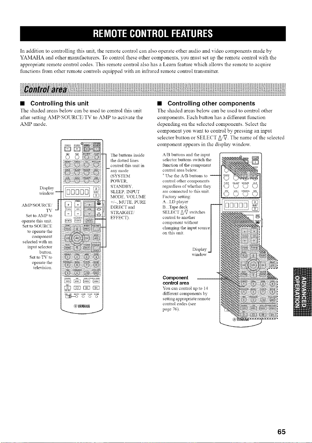
In addition to controlling this unit, the remote control can also operate other audio and video components made by
YAMAHA and other manufacturers. To control these other components, you must set up the remote control with the
appropriate remote control codes. This remote control also has a Learn feature which allows the remote to acquire
functions from other remote controls equipped with an infrared remote control transmitter.
• Controlling this unit
The shaded areas below can be used to control this unit
after setting AMP/SOURCBTV to AMP to activate the
AMP mode.
Display
window --
AMP/SOURCE/
TV
Set to AMP to
operate this unit.
Set to SOURCE
to operate the
conlponent
selected with an
input selector
button.
Set to TV to
operate the
television.
The buttons inside
the dotted lines
coni]ol this unit in
- any, mode
(SYSTEM
POWER,
STANDBY,
SLEEP, INPUT
MODE, VOLUME
+,' , MUTE, PURE
DIRECT and
STRAIGHT,,'
EFFECT)
• Controlling other components
The shaded areas below can be used to control other
components. Each button has a different function
depending on the selected components. Select the
component you want to control by pressing an input
selector button or SELECT A_. The name of the selected
component appears in the display window.
AiB buttons and the input
selector buttons switch tlle
flmcfion of the component
contzol area below
* Use the A,'B buttons to --
control other components
regmdless of whether flmy
are connected to this unit
Factory setting:
A..LD player
B..Tape deck
SELECT A/_ switches
connol to another
component without
changing the input source
on this trait
Display
window
Component
control area
You can control up to 14
different components by
setting appropriate remote
control codes (see
page 76).
r,====:=_N:
ED
65
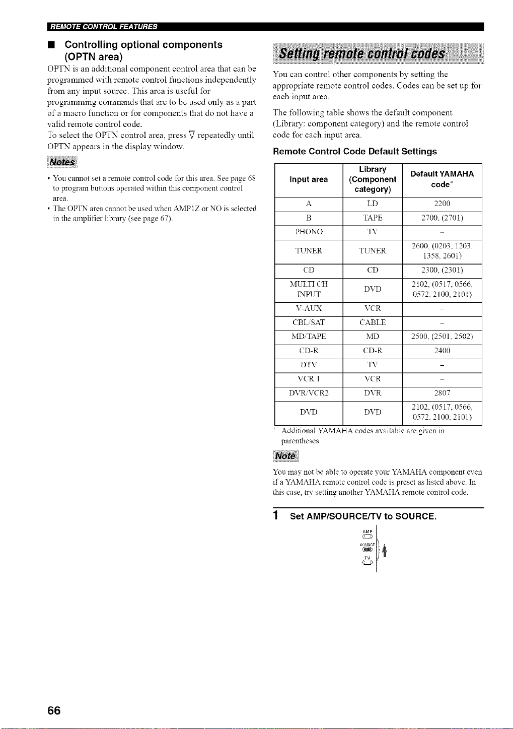
|:t;li_[oll:l_*o]_TIl:[o]ll___|lll:t_
• Controlling optional components
(OPTN area)
OPTN is an additional component control area that can be
programmed with remote control functions independently
fi'om any input source. This area is useful for
programming commands that are to be used only as a part
of a macro function or for components that do not have a
valid remote control code.
To select the OPTN control area, press V repeatedly until
OPTN appears in the display window.
• You camlot set a remote control code for this area. See page 68
to program buttons operated within this component control
area.
• The OPTN area cannot be used when AMP1Z or NO is selected
in the anaplifier libral T (see page 67).
You can control other components by setting the
appropriate remote control codes. Codes can be set up for
each input area.
The following table shows the default component
(Library: component category) and the remote control
code for each input area.
Remote Control Code Default Settings
Library Default YAMAHA
Input area (Component code*
category)
A LD 2200
B TAPE 2700, (2701)
PHONO _T
2600, (0203. 1203,
TL_ER TL_P'4ER
1358, 2601)
CD CD 2300, (2301)
MULTI CH DVD 2102 (0517, 0566.
INPUT 0572, 2100, 2101)
V-AUX VCR
CBL SAT CABLE
MD TAPE MD 2500. (2501, 2502)
CD-R CD-R 2400
DTV TV
VCR 1 VCR
DVtL VCR2 DVR 2807
2102. (0517, 0566,
DVD DVD
0572. 2100 2101)
Additional YAMAHA codes available are given in
parentheses.
You may not be able to operate your YAMAHA component exen
ifa YAMAHA remote control code is preset as listed above. In
this case, try setting another YAMAHA remote control code.
Set AMP/SOURCE/TV to SOURCE.
sc_uRcg
66
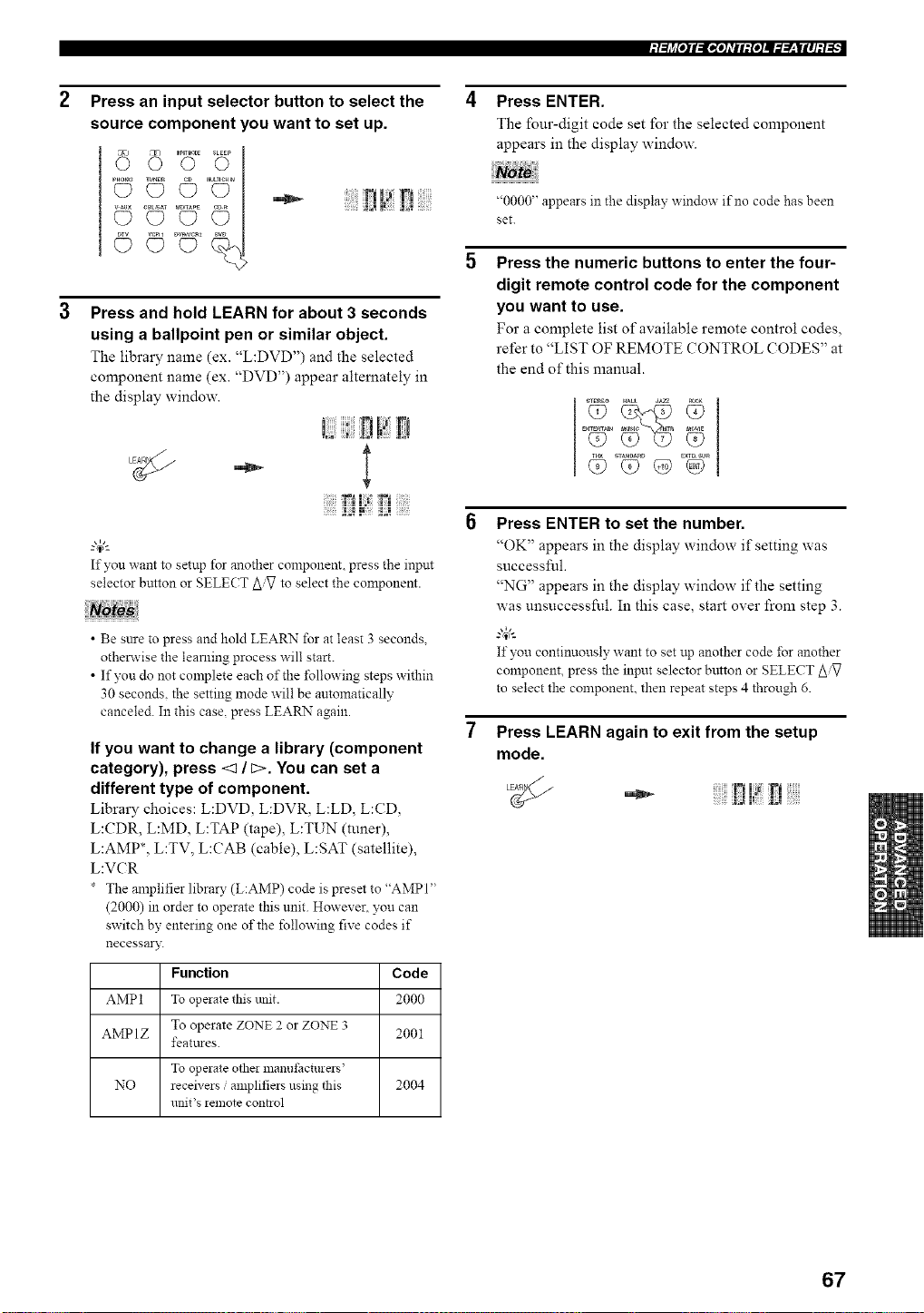
Press an input selector button to select the
source component you want to set up.
I? [',i
Press and hold LEARN for about 3 seconds
using a ballpoint pen or similar object.
The library name (ex. "L:DVD") and the selected
component name (ex. "DVD") appear alternately in
the display window.
!?!!Ei
If you want to setup for another component, press the input
selector button or SELECT to select the component.
• Be sure to press and hold LEARN for at least 3 seconds,
otherwise the learning process will start.
• If yon do not complete each of the following steps within
30 seconds, the setting mode will be automatically
canceled. In this case, press LEARN again.
If you want to change a library (component
category), press <1 / c>. You can set a
different type of component.
Library choices: L:DVD, L:DVR, L:LD, L:CD,
L:CDR, L:MD, L:TAP (tape), L:TUN (tuner),
LAMP*, L:TV, L:CAB (cable), L:SAT (satellite),
L:VCR
The anaplifierlibrary (L:AMP) code is preset to "AMPI"
(2000) in order to operate this unit. However, you can
switch by entering one of the following five codes if
necessary.
Function Code
AMP1 To opeiate this unit. 2000
AMP 1Z To operate ZONE 2 or ZONE 3 2001
featttres.
To operate othei manut:acturers'
NO receivers ,'amplifiers using this 2004
unit's *emote contaol
Press ENTER.
The four-digit code set for the selected component
appears in the display window.
"0000" appears in the display window if no code has been
set.
Press the numeric buttons to enter the four-
digit remote control code for the component
you want to use.
For a complete list of available remote control codes,
refer to "LIST OF REMOTE CONTROL CODES" at
the end of this manual.
_TE_EO HALL JA_
Press ENTER to set the number.
"OK" appears in the display window if setting was
successful.
"NG" appears in the display window if the setting
was unsuccessful. In this case, start over from step 3.
g_'-
If you continuously want to set up another code for another
component, press the input selector button or SELECT Z_iV
to select the component, then repeat steps 4 through 6.
Press LEARN again to exit from the setup
mode.
•_- !71 r!
_ ;_ i_ _ _i_,• _
67
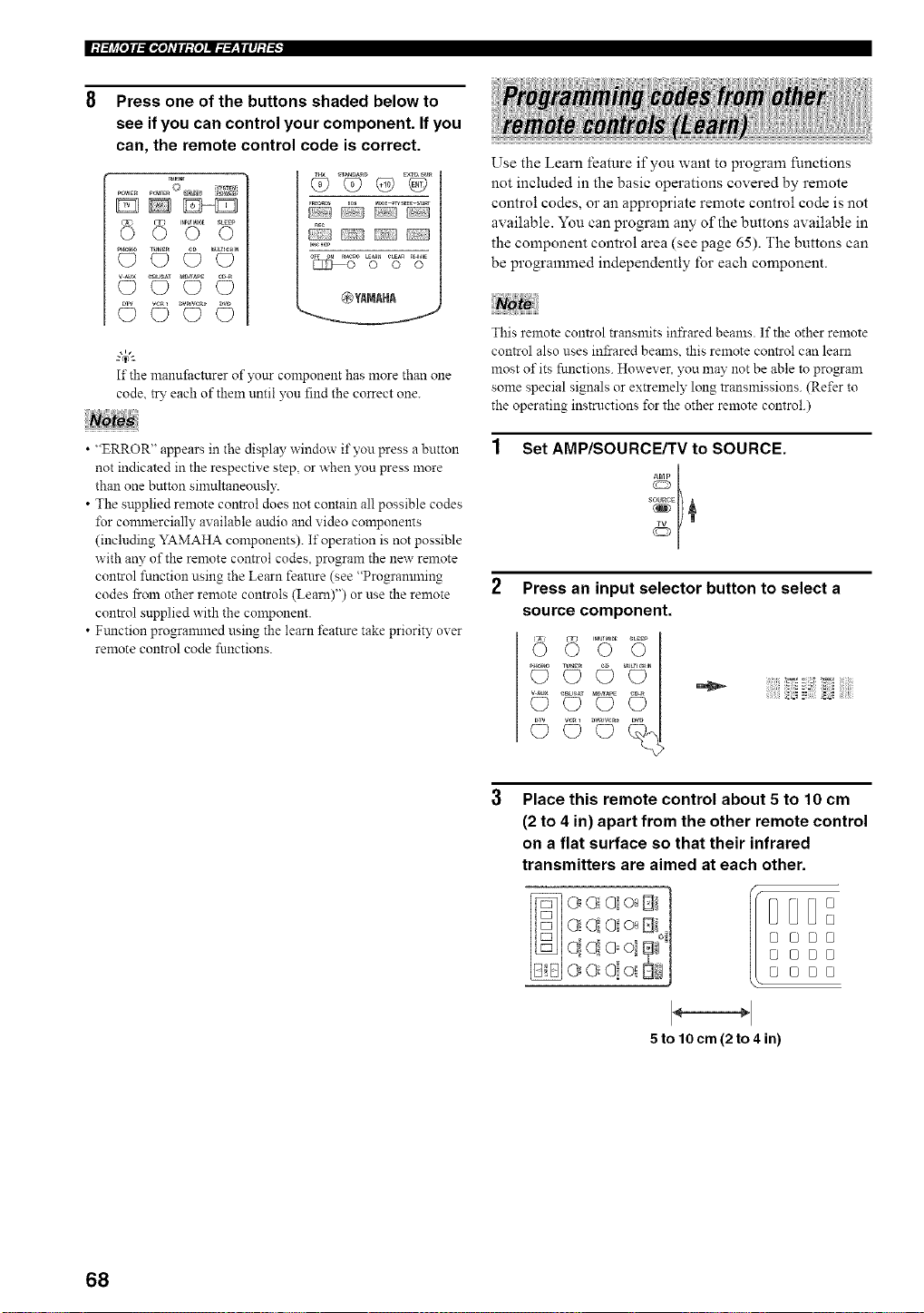
Press one of the buttons shaded below to
see if you can control your component. If you
can, the remote control code is correct.
TR_"_T
DD_
_o_o_ (_ _ _TU_ER _IU/T_CmN
@YAMAHA
gc_)I-_
If the manufi_cturer of your component has more than one
code, try each of theln until you find the correct one.
• "ERROR" appears in the display window if you press a button
not indicated in the respective step, or when you press more
than one button simultaneously.
• The supplied remote control does not contain all possible codes
I%r connnercially available audio and video components
(including YAMAHA components). If operation is not possible
with any of the remote control codes, program the new remote
control function using the Learn featnre (see "Progrannning
codes from other remote controls (Learn)") or use the remote
control snpplied with the component.
• Ftmction progrannned using the learn featttre take priority over
remote control code functions.
Use the Learn feature if you want to program functions
not included in the basic operations covered by remote
control codes, or an appropriate remote control code is not
available. You can program any of the buttons available in
the component control area (see page 65). The buttons can
be programmed independently for each component.
This remote control transmits infrared beams. If the other remote
control also uses infrared beams, this remote control can learn
most of its functions. However. you may not be able to program
some special signals or extremely long transmissions. (Refer to
the operating instructions for the other remote control.)
Set AMP/SOURCE/TV to SOURCE.
Press an input selector button to select a
source component.
© *©',©o
©
Place this remote control about 5 to 10 cm
(2 to 4 in) apart from the other remote control
on a flat surface so that their infrared
transmitters are aimed at each other.
oi t %1
e e!oi StiJ
I D
@@[J0
@ @B@
5 to lOcm (2to 4 in)
68
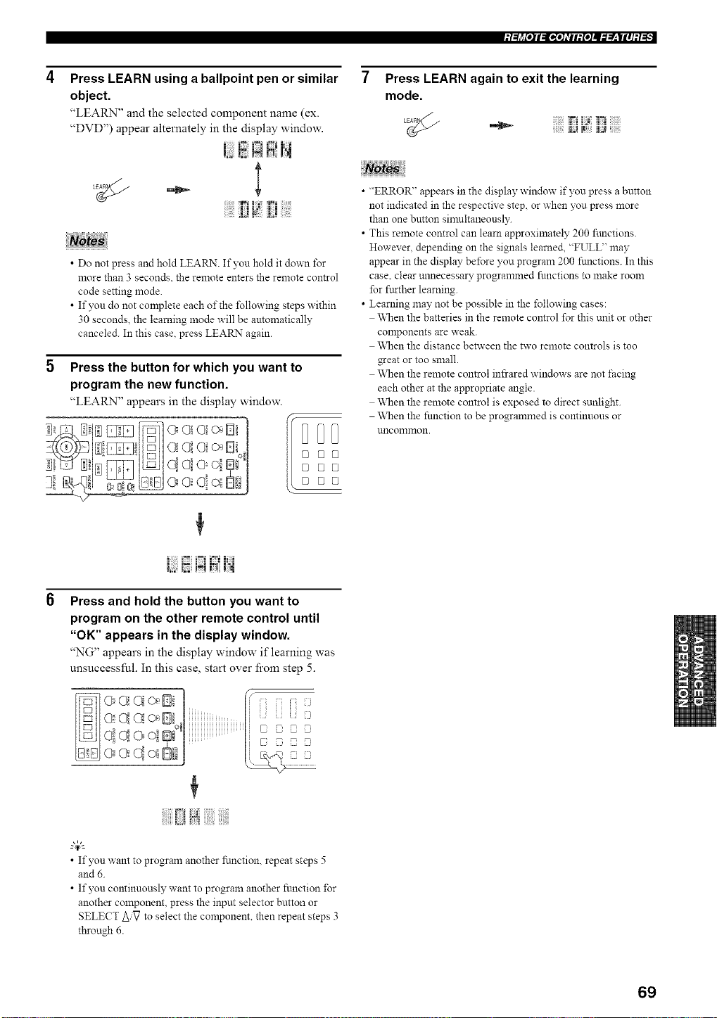
Press LEARN using a ballpoint pen or similar
object.
"LEARN" and the selected component name (ex.
"DVD") appear alternately in the display window.
• Do not press and hold LEARN. If yon hold it down for
more than 3 seconds, the remote enters the remote control
code setting mode.
• If yon do not complete each of the following steps within
30 seconds, the learning mode will be automatically
canceled. In this case, press LEARN again.
5 Press the button for which you want to
program the new function.
"LEARN" appears in the display window.
]i a ol o.D i'|
I _ I I:l
Press and hold the button you want to
program on the other remote control until
"OK" appears in the display window.
"NG" appears in the display window if learning was
unsuccessful. In this case, start over from step 5.
-0 _0 . i i]i i]ii]i_J
o0oi m'1
• If yon want to program another function, repeat steps 5
and 6.
• If yon continuously want to program another fnnction ±Br
another component, press the input selector button or
SELECT AiV to select the component, then repeat steps 3
through 6.
Press LEARN again to exit the learning
mode.
• "ERROR" appears in the display window if you press a button
not indicated in the respective step, or when you press more
than one button sinmltaneonsly.
• This remote control can learn approximately 200 ftmctions.
However, depending on the signals learned, "FULL" may
appear in the display before you program 200 functions. In this
case. clear unnecessal7 programmed fnnctions to make room
for further learning.
• Learning n'mynotbe possible in the following cases:
When the batteries in the remote control for this unit or other
conaponents are weak.
\_]_enthe distance between the two remote controls is too
gear or too small.
\_]_enthe remote control infrared windows are not facing
each other at the appropriate angle.
\_]_enthe remote control is exposed to direct sunlight.
\_]_enthe function to be programmed is continuous or
uncommon.
69
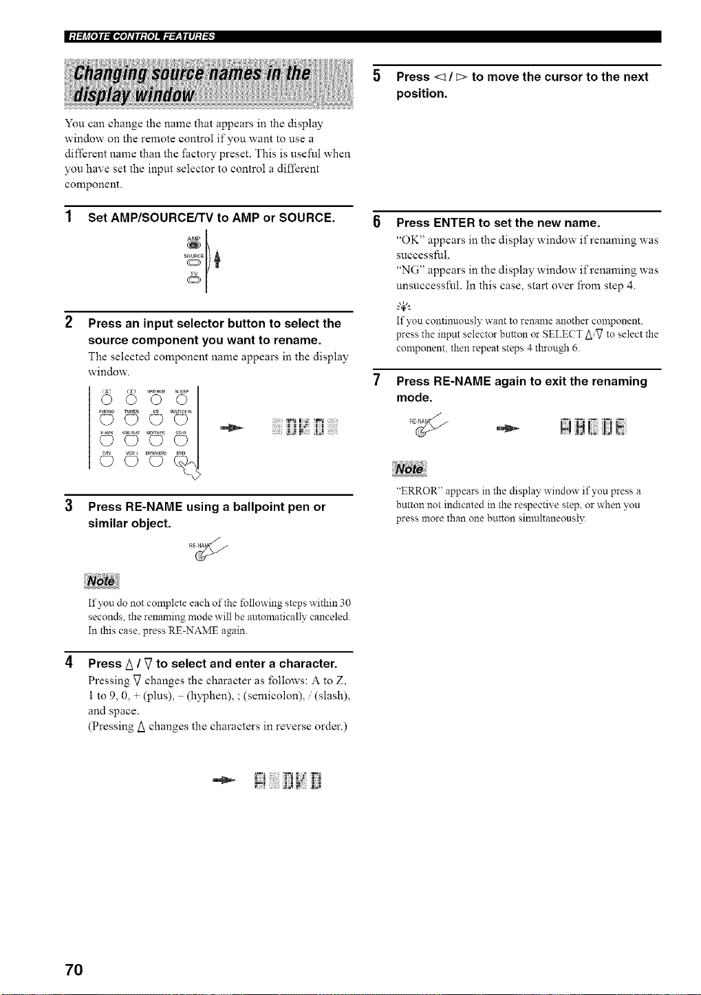
You can change the name that appears in the display
window on the remote control if you want to use a
different name than the factory preset. This is useful when
you have set the input selector to control a different
component.
Set AMP/SOURCE/TV to AMP or SOURCE.
Press an input selector button to select the
source component you want to rename.
The selected component name appears in the display
window.
voZ l
Press RE-NAME using a ballpoint pen or
similar object.
5 Press <_ / E> to move the cursor to the next
position.
Press ENTER to set the new name.
"OK" appears in the display window if renaming was
successful.
"NG" appears in the display window if renaming was
unsuccessful. In this case, start over fi'om step 4.
g4;'-
If you continuously want to rename another component,
press the input selector button or SELECT AiVto select the
component, then repeat steps 4 through 6.
Press RE-NAME again to exit the renaming
mode.
"ERROR" appears in the display, window if you press a
button not indicated in the respective step, or when you
press more than one button simultaneously.
If you do not complete each of the following steps within 30
seconds, the renaming mode will be automatically canceled.
In this case. press RE-NAME again.
Press/_ / V to select and enter a character.
Pressing V changes the character as follows: A to Z,
1 to 9, 0, + (plus), (hyphen), ; (semicolon), / (slash),
and space.
(Pressing/_ changes the characters in reverse order.)
70
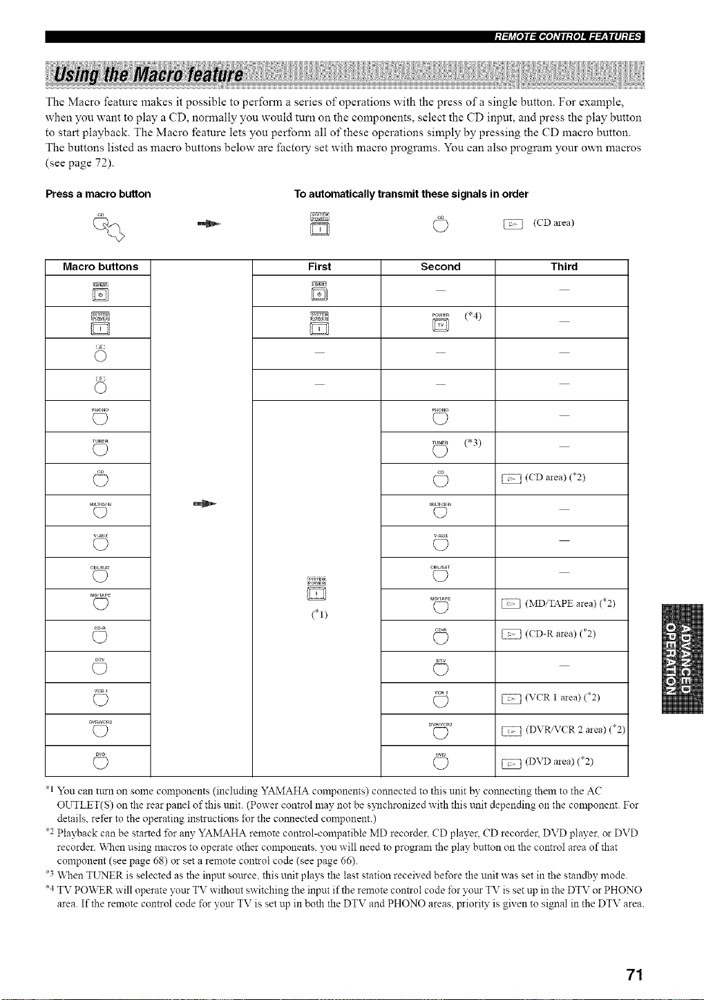
The Macro feature makes it possible to perform a series of operations with the press of a single button. For example,
when you want to play a CD, normally you would turn on the components, select the CD input, and press the play button
to start playback. The Macro feature lets you perform all of these operations simply by pressing the CD macro button.
The buttons listed as macro buttons below are facto W set with macro programs. You can also program your own macros
(see page 72).
Press a macro button
To automatically transmit these signals in order
(CD mea)
Macro buttons
TUNER
rau_ncH_
v-Au×
CB_Af
MDJ_PE
VCRI
DV_NC_2
First
(*I)
Second
(*4)
(D
(*3)
C?
C?
(D
C?
(D
(D
C)
Third
(CD area) (*2)
(MDiTAPE area) (*2)
(CD-R area) (*2)
(VCR 1 area) (*2)
(DVR/VCR 2 area) (*2)
(DVD area) (*2)
*1 You can turn on some components (including YAMAHA components) com_ected to this unit by com_ecting them to the AC
OUTLET(S) on the rear panel of this unit. (Power control may not be s?_chronized with this unit depending on the component. For
details, refer to the operating instructions ±\_rthe com_ected component.)
*2 Playback can be started *\_r any YAMAHA remote control-compatible MD recorder. CD player, CD recorder. DVD player, or DVD
recorder. When using macros to operate other components, you will need to program the play button on the control area of that
component (see page 68) or set a remote control code (see page 66).
*3 When TL_rNERis selected as the input sottrce, this unit plays the last station received before the unit was set in the standby mode.
*4 TV PO\_R will operate your TV without switching the input if the remote control code for yottr TV is set up in the DTV or PHONO
area. If the remote control code *\_ryour TV is set up in both the DTV and PHONO areas, priority is given to signal in the DTV area.
71
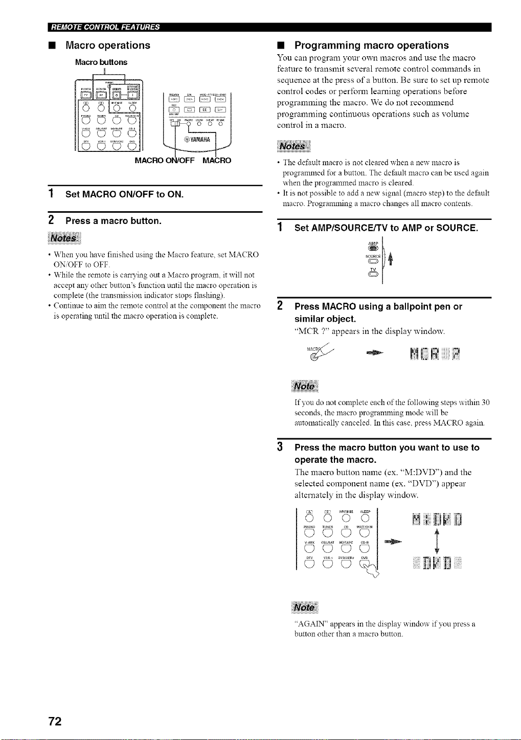
• Macro operations
Macro buttons
• Programming macro operations
You can program your own macros and use the litacro
feature to transmit several remote control commands in
sequence at the press of a button. Be sure to set up remote
control codes or perform learning operations before
programming the macro. We do not recommend
programming continuous operations such as volume
control in a macro.
1 Set MACRO ON/OFF to ON.
2 Press a macro button.
• When you have finished using the Macro feature, set MACRO
ON/OFF to OFF.
• While the remote is carrying out a Macro program, it will not
accept any other bmton's function until the macro operation is
complete (the transmission indicator stops flashing).
• Continue to aim the remote con_ol at the component the macro
is operating until the macro operation is complete.
• The dd'ault macro is not cleared when a new macro is
progrannned for a button. The default macro can be used again
when the programmed macro is cleared.
• It is not possible to add a new signal (macro step) to the de±;ault
macro. Progrannning a macro changes all macro contents.
Set AMP/SOURCE/TV to AMP or SOURCE.
s 01)¢
2 Press MACRO using a ballpoint pen or
similar object.
"MCR ?" appears in the display window.
If you do not complete each of the following steps within 30
seconds, the macro prnganuning mode will be
automatically canceled. In this case, press MACRO again.
Press the macro button you want to use to
operate the macro.
The macro button name (ex. "M:DVD") and the
selected component name (ex. "DVD") appear
alternately in the display window.
6 "":'.......!! [!
© <4>1 ::::::J::J_:'!::[:ii:::::::
"AGAIN" appears in the display window if you press a
button other than a macro button.
72
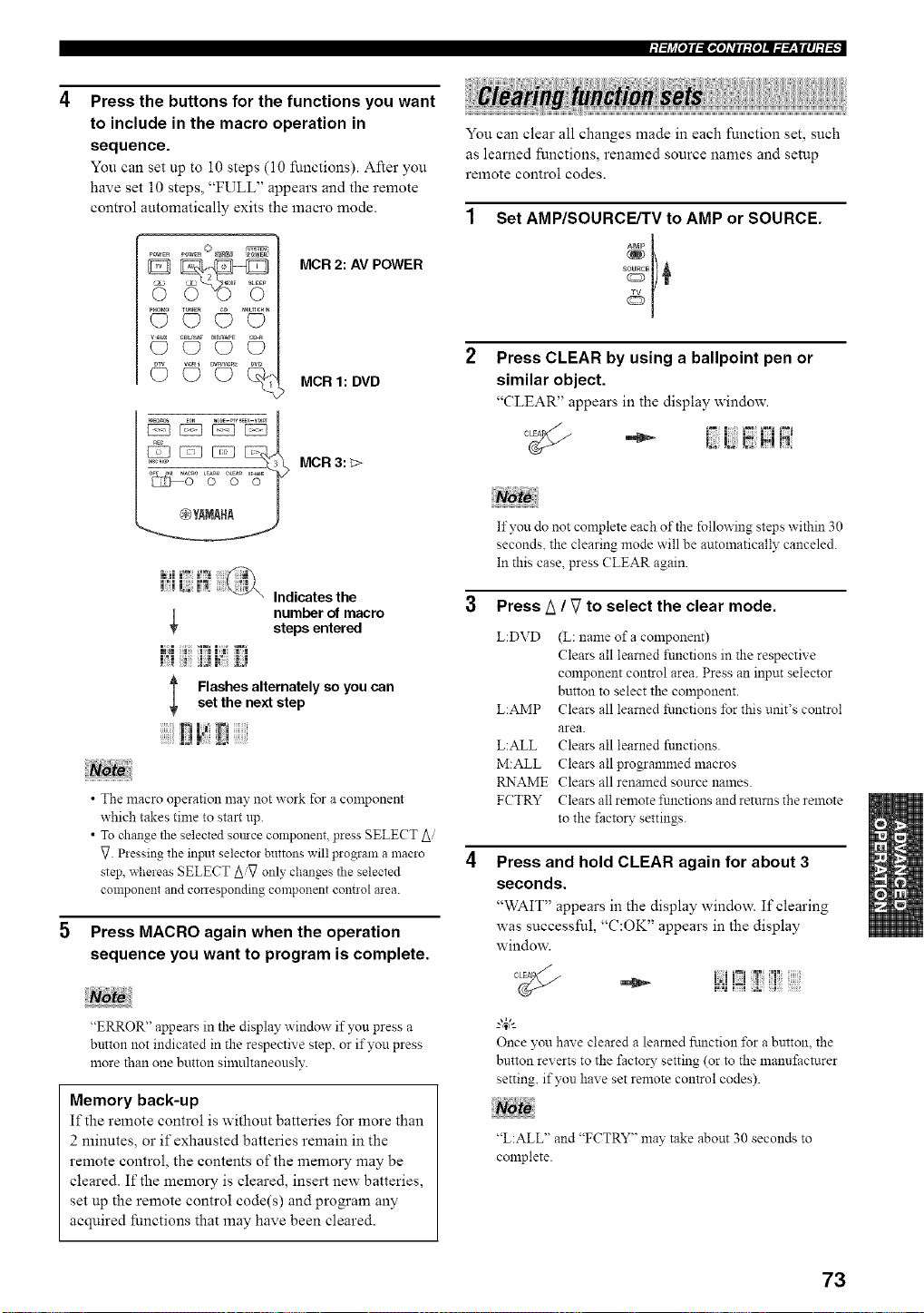
Press the buttons for the functions you want
to include in the macro operation in
sequence.
You can set up to 10 steps (10 functions). After you
have set 10 steps, "FULL" appears and the remote
control automatically exits the macro mode.
_ M®E _EEP
pHr_o(_ TUNE_Q__) rAutnemN(_
_R_eR_ DW
©©c)%
MCR 2: AV POWER
MCR 1: DVD
MCR 3: _>
You can clear all changes made in each function set, such
as learned functions, renamed source names and setup
remote control codes.
Set AMP/SOURCE/TV to AMP or SOURCE.
Press CLEAR by using a ballpoint pen or
similar object.
_CLEAR" appears in the display window.
Indicates the
number of macro
steps entered
l Flashes alternately so you canset the next step
• The macro operation may not work for a component
which takes time to start up.
• To change the selected somce component, press SELECT Ai
_. Pressing the inpnt selector buttons will program a macro
step, whereas SELECT Ai_ only changes tile selected
component and conesponding component cont!ol area.
Press MACRO again when the operation
sequence you want to program is complete.
"ERROR" appears in the display window if you press a
button not indicated in the respective step, or if you press
more than one button silnultaneously.
Memory back-up
If the remote control is without batteries for more than
2 minutes, or if exhausted batteries remain in the
remote control, the contents of the memory may be
cleared. If the memory is cleared, insert new batteries,
set up the remote control code(s) and program any
acquired functions that may have been cleared.
If you do not complete each of the following steps within 30
seconds, the clearing mode will be automatically canceled.
In this case. press (?LEAR again.
3 Press A / V to select the clear mode.
L:DVD (L: name of a component)
Clears all learned _imctions in the respective
component control area. Press an input selector
button to select the component.
L:AMP Clears all learned functions for this unit's control
area.
L:ALL Clears all learned functions.
M:ALL Clears all programmed macros
RNAME Clears all renanaed source names.
FCTRY Clears all remote functions and returns the remote
to the factory settings.
Press and hold CLEAR again for about 3
seconds.
'_WAIT" appears in the display window. If clearing
was successful, "C:OK" appears in the display
window.
°_ i:;!!iZ!!: !
Once you have cleared a learned fnnction for a button, the
button reverts to the factory setting (or to the manufacturer
setting, if you have set remote control codes).
"L:ALL" and "FCTRY" may take about 30 seconds to
complete.
73
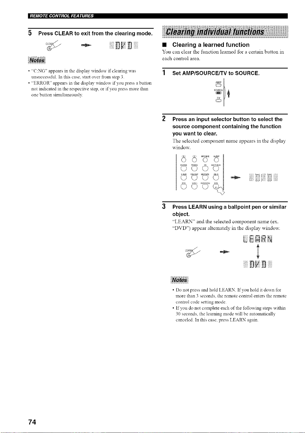
5 Press CLEAR to exit from the clearing mode.
• "C:NG" appears in the display window if clearing was
unsuccessful. In this case, start over from step 3.
• "ERROR" appears in the display window if you press a button
not indicated in the respective step, or if you press more than
one breton simultaneonsl?_
• Clearing a learned function
You can clear the ftn_.ctiol_, learned for a certain buttol_, in
each control area.
1 Set AMP/SOURCE/TV to SOURCE.
Press an input selector button to select the
source component containing the function
you want to clear.
The selected component name appears in the display
window.
,2 .................................
Press LEARN using a ballpoint pen or similar
object.
"LEARN" and the selected component name (ex.
"DVD") appear alternately in the display window.
- l
• Do not press and hold LEARN. If yon hold it down for
more than 3 seconds, the remote control enters the remote
control code setting mode.
• If you do not complete each of the following steps within
30 seconds, the learning mode will be antomatically
canceled. In this case, press LEARN again.
74
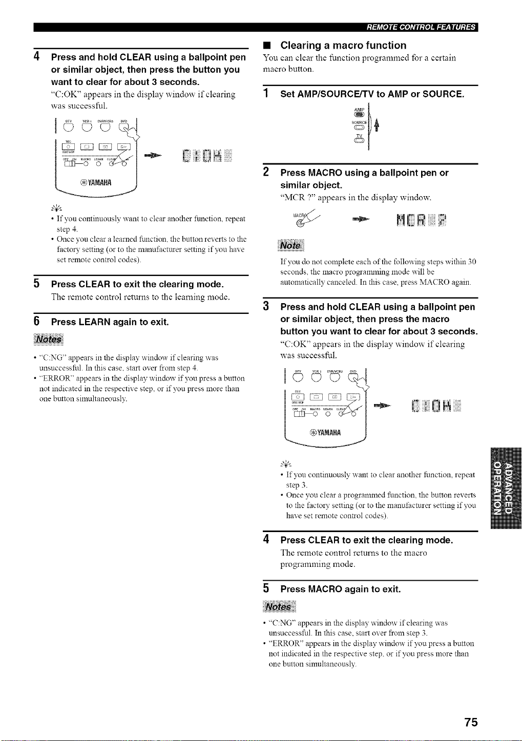
Press and hold CLEAR using a ballpoint pen
or similar object, then press the button you
want to clear for about 3 seconds.
"(':OK" appears in the display window if clearing
was successful.
/
"4;:
• If you continuously want to clear another ftmction, repeat
step 4.
• Once you clear a learned ftmction, the button reverts to the
f:actoW setting (or to the manuf:actttrer setting if you have
set remote control codes).
5 Press CLEAR to exit the clearing mode.
The remote control returns to the learning mode.
6 Press LEARN again to exit.
• "C:NG" appears in the display window if clearing was
unsuccessful. In this case. start over from step 4.
• "ERROR" appears in the display window if you press a button
not indicated in the respective step, or if you press more than
one button simultaneously.
• Clearing a macro function
You can clear the function programmed for a certain
macro button.
Set AMP/SOURCE/TV to AMP or SOURCE.
Press MACRO using a ballpoint pen or
similar object.
"MCR ?" appears in the display window.
If you do not complete each of the following steps within 30
seconds, the macro progranmling mode will be
antomatically canceled. In this case, press MACRO again.
Press and hold CLEAR using a ballpoint pen
or similar object, then press the macro
button you want to clear for about 3 seconds.
"C:OK" appears in the display window if clearing
was successful.
"*- ! 0ii
• If you continuously want to clear another function, repeat
step 3.
• Once you clear a programmed function, the button reverts
to the factory setting (or to the manufacturer setting if you
have set remote con_ol codes).
4 Press CLEAR to exit the clearing mode.
The remote control returns to the macro
programming mode.
5 Press MACRO again to exit.
• "C:NG" appears in the display window if clearing was
unsuccessful. In this case. start over from step 3.
• "ERROR" appears in the display window if you press a button
not indicated in the respective step, or if you press more than
one button sinmltaneously.
75
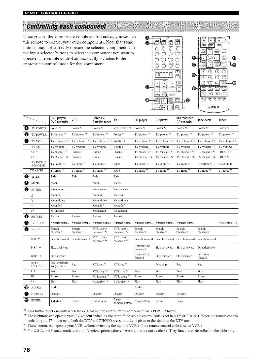
Once you set the appropriate remote control codes, you can use
this remote to control your other components. Note that some
buttons may not correctly operate the selected component. Use
the input selector buttons to select the component you want to
operate. The remote control automatically switches to the
appropriate control mode for that component.
VUOoO "
OOOO
0000
0-
0-
tQ
..@
1_8 +%° +8=%=
@YtltRt
DVDplayer/ Cable TV/ MDrecorder/
_-_ DVDrecorder VCR Satellite tuner TV LD player CD player CD recorder Tapedeck Tuner
AV PO_VER Po'_ei .1 Po_er <1 Po_ e1 *1 V('R 1]o_ei *3 Po_el <1 Po_el *1 Po'_ei * 1 Po_ei .1 Po_e1.1
TV PO\VER TV po_ei _2 TV powel *2 TV powel *2 Po'_ e1 * 1 TV powel *2 TV powel *2 TV po,_ e1 *2 TV powel _2 TV powel *2
TV VOL + TV _ohllne + *2 TXr volllme *2 TV volunte + *2 Volttlne + TX r vollillte + *2 TXr volume + *2 TV vohnne + *2 TV _oltllne + *2 TXr voltllne + *2
TV VOL TV volllllte *2 TV vohlne *2 TV _ohllne *2 Voltllne TV vohline *2 TV vohline *2 TV vohllne *2 TV vohlllte *2 TV vohlne *2
CH + TV channel + 2 Channel (haimeI + ('halmel + TV cllannel + *2 TV chmmel .2 TV channel + *2 TV channel + 2 PRESET +
('H TV chalineI *2 Chailild (haitlle] Challilel TV cilal_ilel *2 TV challilel *2 TV chalineI 2 TV chailllel 2 PRESET
TV ENPUT/
A B_CID/E TV input '2 TV inptlt *2 TV input *2 Input TV inlmt *2 TV input *2 TV input "2 Dflection ,_,'B A,iB C D E
TV MUTE TV mllte *2 TV nlttte *2 TV Inllte *2 ]_,Illt e TV little *2 TV Inttte *2 TV mllte *2 TV lnllte *2 TV Inttte *2
TITLE Title Title Title Title
MENU Menu Menu Menu
O ENTER Menu entel Menu select Metal selec*
/k Menu tip Menu up Menu tip
_7 Metal doun Menu down Melm doan
<el Melm left Menu left Melm left
[:> Melm liN_ blenu _ight Melm right
RETURN Retmn Rettm_ Remm Retmn
O 1-9.0. +10 Ntm_elic buttons Numetic bnlons Ntm_exic buttons Numelic buttons Ntm_eiic buttons Ntm_eiic buttons Nmnelic buttons Beset stalons (1-8)
<_<_ *4 Semch Semch VCR semch VCR _ealch Semch Semch Sealch Semch
backv, ald back_a*d backwmd *? backv, ald *3 backa ard backward backv, md back_ md
VCR semch VCR _ealch
[:>C> *4 Semch fo*a_md Semch fo*_md Semch folamd Semch fonvmd Semch fo_wald Semch fo*a_md
back_ a*d .3 back_ aid *3
ChapteliSldp Skipback_a*d Skip backamd Dflectionback
b<t<l *4 Skip backx_a*d backaard
Dq>{ *4 Skip folamd Chaptel,'Skip Skip fo*_ald Sldp folamd Direction
folaard fo_a_ a*d
REC/ Disc skip (player)
DISC SKIP Rec (lecoldel) Rec VCR _ec *3 VCR rec *? Disc skip Rec Rec
[] Stop Stop VCR stop *3 VCR stop *3 Stop Stop Stop Stop
II Pause Pause VCR pause *3 VCR pause *3 Pause Pause Pause Pause
[:> Pay Play VCR pay *3 VCR play *3 Play Play Pay Play
AUDIO Audio Audio
DISPLAY D sp ay D sp ay D sp ay Display Display D sp ay
En_m Chaptel/Time Index Index
ENTER TitlelIndex Enter Enteli_ecalt numeric button
• 1 This button fimctions only when the original *emote control of the colnponent has a POWER button.
*2 These buttons can operate your TV without switching the input if the remote control code is set in DTV or PHONO When the remote control
code for yore TV is set up in both the DTV and PHONO areas, priori_, is given to the signal in the DTV area.
*3 These buttons can operate your VCR wil_out switching the input to VCR 1 if the relnote control code is set in VCR 1.
*4 For U.S.A. and Canada models, button fimctions printed above these buttons are not available They fimction as described in the table only
76
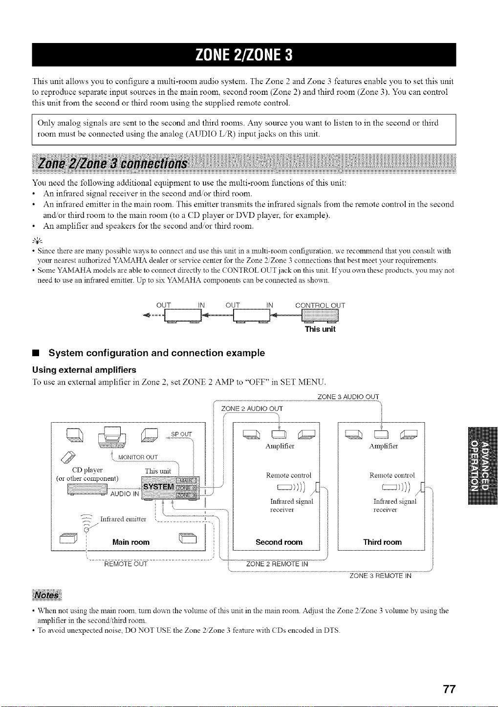
This unit allows you to configure a multi-room audio system. The Zone 2 and Zone 3 features enable you to set this unit
to reproduce separate input sources in the main room, second room (Zone 2) and third room (Zone 3). You can control
this unit fi'om the second or third room using the supplied remote control.
Only analog signals are sent to the second and third rooms. Any source you want to listen to in the second or third
room must be connected using the analog (AUDIO LR) input jacks on this unit.
You need the following additional equipment to use the multi-room functions of this unit:
• An infrared signal receiver in the second and, or third room.
• An infrared emitter in the main room. This emitter transmits the infi'ared signals from the remote control in the second
and, or third room to the main room (to a CD player or DVD player, for example).
• An amplifier and speakers for the second and/or third room.
• Since there are many possible ways to colmect and use this unit in a multi-room confi_lration, we reconmlend that you consult with
your nearest authorized YAMAHA dealer or service center for the Zone 2/Zone 3 connections that best meet your requirements.
• Some YAMAHA models are able to connect directly to the CONTROL OUT jack on this unit. If you own these products, you may not
need to use an infrared emitter. Up to six YAMAHA corn )onents cau be colmected as shown.
OUT IN OUT IN CONTROL OUT
This unit
• System configuration and connection example
Using external amplifiers
To use an external amplifier in Zone 2, set ZONE 2 AMP to "OFF" in SET MENU.
ZONE 3 AUDIO OUT
ZONE 2 AUDIO OUT
Amplifier
Renlote co!it1 ol
Infiaied signal
receiver
Third room
REMOTE OUT
ZONE 3 REMOTE IN
• When not using the main room, turn down the voltmle of this unit in the main room. Ac[iust the Zone 2Zone 3 volulne by using the
amplifier in the second third room.
• To avoid unexpected noise, DO NOT USE the Zone 2Zone 3 feature with CDs encoded in DTS.
77
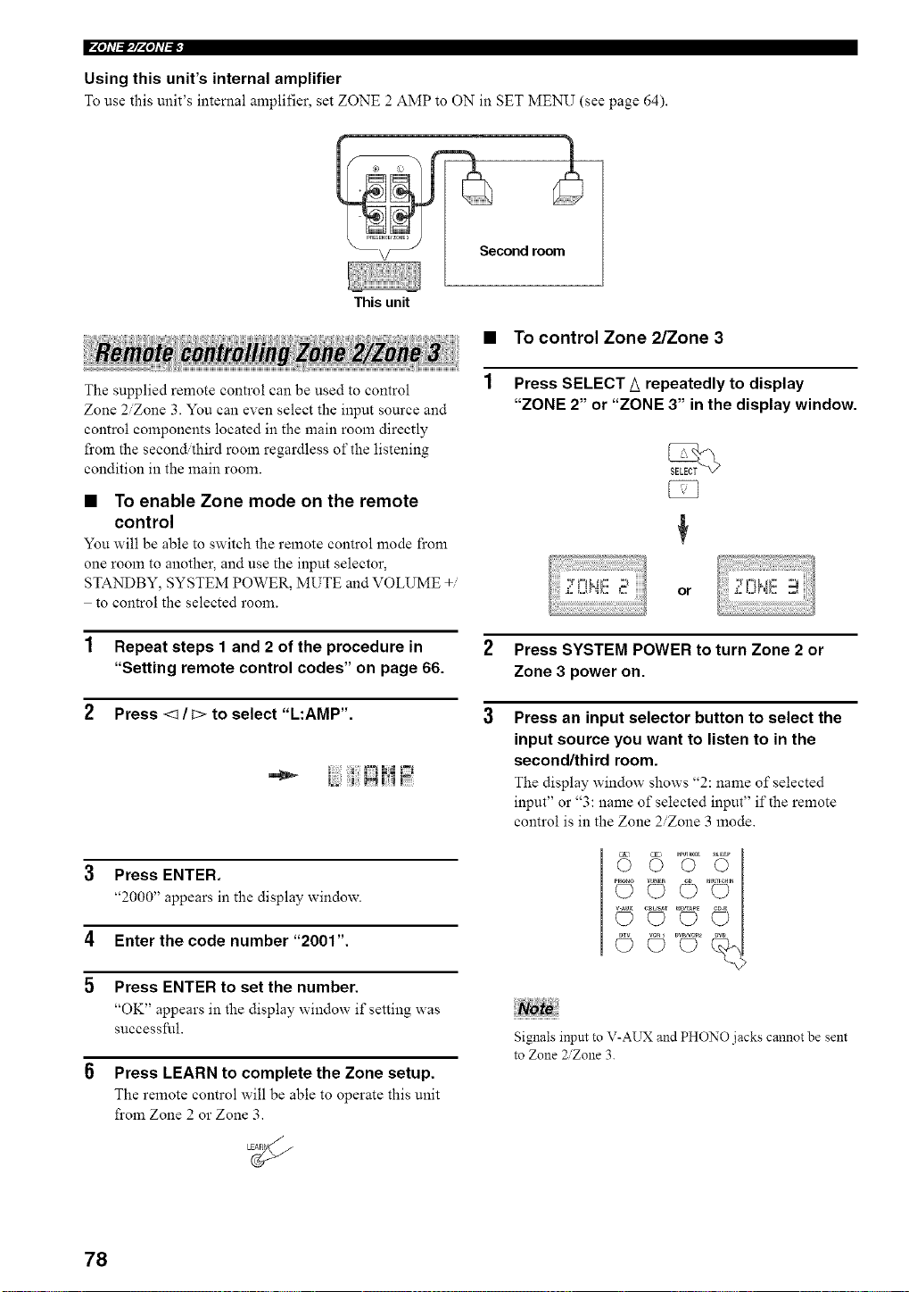
F'Ph'(_IpPh'I_F
Using this unit's internal amplifier
To use this unit's internal amplifier, set ZONE 2 AMP to ON in SET MENU (see page 64).
This unit
Second room_
• TO control Zone 2/Zone 3
The supplied remote control can be used to control
Zone 2/Zone 3. You can even select the input source and
control components located in the main room directly
from the second,ihird room regardless of the listening
condition in the main room.
• To enable Zone mode on the remote
control
You will be able to switch the remote control mode from
one room to another, and use the input selector,
STANDBY, SYSTEM POWER, MUTE and VOLUME +/
to control the selected room.
Press SELECT A repeatedly to display
"ZONE 2" or "ZONE 3" in the display window.
or
2 Press SYSTEM POWER to turn Zone 2 or
Zone 3 power on.
3 Press an input selector button to select the
input source you want to listen to in the
second/third room.
The display window shows "2: name of selected
input" or "3: name of selected input" if the remote
control is in the Zone 2/Zone 3 mode.
1 Repeat steps 1 and 2 of the procedure in
"Setting remote control codes" on page 66.
2 Press <1 / C>to select "L:AMP'.
1 |:;i FLqi.J
3 Press ENTER.
"2000" appears in the display window.
4 Enter the code number "200t".
5 Press ENTER to set the number.
"OK" appears in the display window if setting was
successful.
6 Press LEARN to complete the Zone setup.
The remote control will be able to operate this unit
from Zone 2 or Zone 3.
Noto
Signals input to V-AUX and PHONO jacks cannot be sent
to Zone 2Zone 3.
78
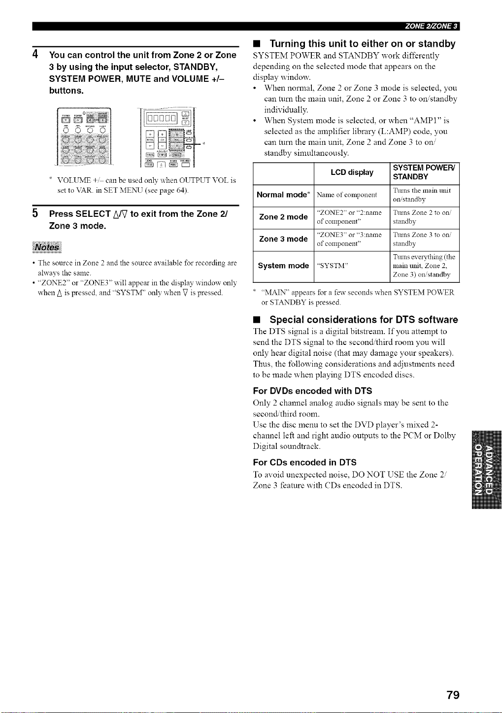
You can control the unit from Zone 2 or Zone
3 by using the input selector, STANDBY,
SYSTEM POWER, MUTE and VOLUME +/-
buttons.
* VOLUME +M can be used only when OUTPUT VOL is
set to \TAR. in SET MEN__T(see page 64).
Press SELECT _/_ to exit from the Zone 21
Zone 3 mode.
• The source in Zone 2 and the source available for recording are
ahvays the same.
• "ZONE2" or "ZONE3" will appear in the display window only
when A is pressed, and "SYSTM" only when g is pressed.
4"h'f_#'4qi'b_-
• Turning this unit to either on or standby
SYSTEM POWER and STANDBY work differently
depending on the selected mode that appears on the
display window.
• When normal, Zone 2 or Zone 3 mode is selected, you
can mm the main unit, Zone 2 or Zone 3 to on/standby
individually.
• When System mode is selected, or when "AMP 1" is
selected as the amplifier library (L:AMP) code, you
can mm the main unit, Zone 2 and Zone 3 to on/
standby simultaneously.
SYSTEM POWER/
LCD display STANDBY
Turns the main trait
Normal mode* Name of component omstandby
"ZONE2" or "2:name Turns Zone 2 to ow
Zone 2 mode
of component' standby
"ZONE3" or "3:name Turns Zone 3 to ow
Zone 3 mode
of component' standby
Turns evmTthing (the
System mode "SYSTM" main unit, Zone 2,
Zone 3) on/standby
"MAIN" appears for a few seconds when SYSTEM POWER
or STANDBY is pressed.
• Special considerations for DTS software
The DTS signal is a digital bitstream. If you attempt to
send the DTS signal to the second/third room you will
only hear digital noise (that may damage your speakers).
Thus, the following considerations and adjustments need
to be made when playing DTS encoded discs.
For DVDs encoded with DTS
Only 2 channel analog audio signals may be sent to the
second/third room.
Use the disc menu to set the DVD player's mixed 2-
channel left and right audio outputs to the PCM or Dolby
Digital soundtrack.
For CDs encoded in DTS
To avoid unexpected noise, DO NOT USE the Zone 2
Zone 3 feature with CDs encoded in DTS.
79
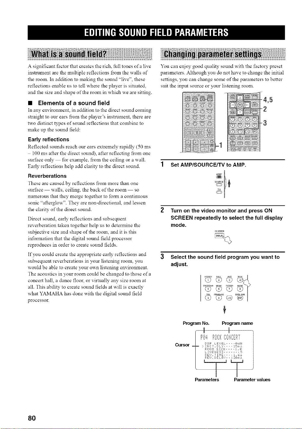
A significant factor that creates the rich, full tones of a live
instrument are the multiple reflections from the walls of
the room. In addition to making the sound "live", these
reflections enable us to tell where the player is situated,
and the size and shape of the room in which we are sitting.
• Elements of a sound field
In any environment, in addition to the direct sound coming
straight to our ears fi'om the player's instrument, there are
two distinct types of sound reflections that combine to
make up the sound field:
Early reflections
Reflected sounds reach our ears extremely rapidly (50 ms
100 ms after the direct sound), after reflecting fi'om one
surface only for example, from the ceiling or a wall.
Early reflections help add clarity to the direct sound.
Reverberations
These are caused by reflections from more than one
surface walls, ceiling, the back of the room so
numerous that they merge together to lbrm a continuous
sonic "afterglow". They are non-directional, and lessen
the clarity of the direct sound.
Direct sound, early reflections and subsequent
reverberation taken together help us to determine the
subjective size and shape of the room, and it is this
information that the digital sound field processor
reproduces in order to create sound fields.
If you could create the appropriate early reflections and
subsequent reverberations in your listening room, you
would be able to create your own listening environment.
The acoustics in your room could be changed to those of a
concert hall, a dance floor, or virtually any size room at
all. This ability to create sound fields at will is exactly
what YAMAHA has done with the digital sound field
processor.
You can enjoy good quality sound with the factory preset
parameters. Although you do not have to change the initial
settings, you can chane some of the parameters to better
suit the input source or our listening room.
-2
Set AMP/SOURCE/TV to AMP.
Ab_P
Turn on the video monitor and press ON
SCREEN repeatedly to select the full display
mode.
0_;_EEN
Select the sound field program you want to
adjust.
T2o'G
Program No. Program name
Cursor E:,sPLE'EL edE_
j: I il I [ _ D L V .... 15 rq
R 0 0 M _, I Z E 1 . k]
L I UENEE;L; ...... ;_,
_ ?RE!l , 7 1 F*E .... ] . _,_
Parameters Parameter values
80
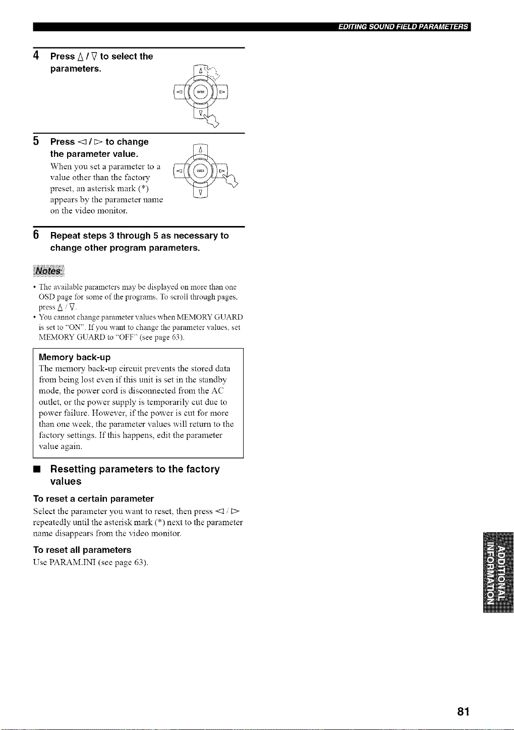
Press A / V to select the
parameters.
Press <_ / _> to change
the parameter value.
When you set a parameter to a
value other than the factory
preset, an asterisk mark (*)
appears by the parameter name
on the video monitor.
6 Repeat steps 3 through 5 as necessary to
change other program parameters.
• The axailable parameters may be displayed on more than one
OSD page for some of the programs. To scroll through pages,
press A V.
• You cannot change parameter values when MEMORY GUARD
is set to "ON". If you want to change the parameter values, set
MEMORY GUARD to "OFF" (see page 63).
Memory back-up
The memory back-up circuit prevents the stored data
from being lost even if this unit is set in the standby
mode, the power cord is disconnected from the AC
outlet, or the power supply is temporarily cut due to
power failure. However, if the power is cut for more
than one week, the parameter values will return to the
factory settings. If this happens, edit the parameter
value again.
• Resetting parameters to the factory
values
To reset a certain parameter
Select the parameter you want to reset, then press <1 t>
repeatedly until the asterisk mark (*) next to the parameter
name disappears from the video monitor.
To reset all parameters
Use PARAM.INI (see page 63).
81
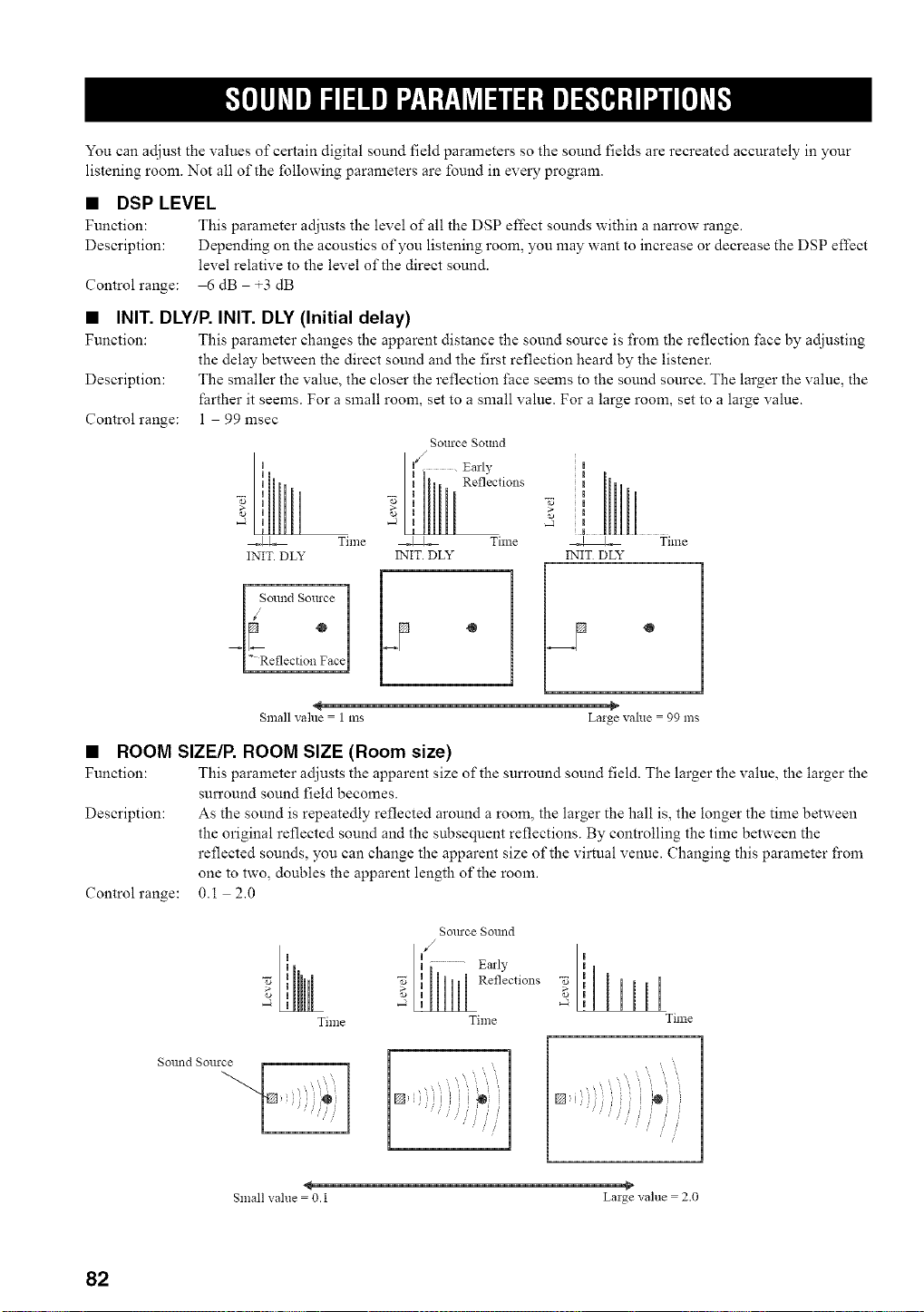
You can adjust the values of certain digital sound field parameters so the sound fields are recreated accurately in your
listening room. Not all of the following parameters are found in every program.
• DSP LEVEL
Function: This parameter adjusts the level of all the DSP effect sounds within a narrow range.
Description: Depending on the acoustics of you listening room, you may want to increase or decrease the DSP effect
level relative to the level of the direct sound.
Controlrange: 6 dB +3 dB
• INIT. DLY/P. INIT. DLY (Initial delay)
Function: This parmneter changes the apparent distance the sound source is fi'om the reflection fi_ce by adjusting
the delay between the direct sound and the first reflection heard by the listener.
Description: The smaller the value, the closer the reflection l_ace seems to the sound source. The larger the value, the
farther it seems. For a small room, set to a small value. For a large room, set to a large value.
Control range: 1 99 msec
Source SOtllld
I _S°llnd Source
°
_LReflection Face
Reflections
.J
_ Time
INIT. DLY
[,-
Small vahle = 1 ms Laige value = 99 ms
• ROOM SIZE/P. ROOM SIZE (Room size)
Function: This parameter adjusts the apparent size of the sun'ound sound field. The larger the value, the larger the
surround sound field becomes.
Description: As the sound is repeatedly reflected around a room, the larger the hall is, the longer the time between
the original reflected sound and the subsequent reflections. By controlling the time between the
reflected sounds, you can change the apparent size of the virtual venue. Changing this parameter fi'om
one to two, doubles the apparent length of the room.
Control range: 0.1 2.0
Time
Sollrce Solmd
al,y 'i
Time
Time
Sollnd Sollrce
' i
,@
Small value = O.l Laige value = 2.0
82
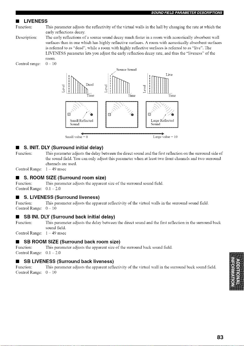
• LIVENESS
Function: This parameter adjusts the reflectivity of the virtual walls in the hall by changing the rate at which the
early reflections decay.
Description: The early reflections of a source sound decay much faster in a room with acoustically absorbent wall
surfaces than in one which has highly reflective surfaces. A room with acoustically absorbent surfaces
is referred to as "dead", while a room with highly reflective surfaces is refen'ed to as "live". The
LIVENESS parameter lets you adjust the early reflection decay rate, and thus the "liveness" of the
room.
Control range: 0 10
II ead
2',
-J !
Time
Source Sound
Live
Time Time
I Small Reflected
Sound
[') "
L\,\ "//
[] / L.-@ 1
I Laige Reflected I
[ So.ha I
Small value = 0 Large value = 10
• S. INIT. DLY (Surround initial delay)
Function: This parameter adjusts the delay between the direct sound and the first reflection on the surround side of
the sound field. You can only adjust this parameter when at least two front channels and two surround
channels are used.
ControlRange: 1 49 msec
• S. ROOM SIZE (Surround room size)
Function: This parameter adjusts the apparent size of the sun'ound sound field.
ControlRange: 0.i 2.0
• S. LIVENESS (Surround liveness)
Function: This parameter adjusts the apparent reflectivity of" the virtual walls in the sun'ound sound field.
Control Range: 0 i0
• SB INI. DLY (Surround back initial delay)
Function: This parameter adjusts the delay between the direct sound and the first reflection in the surround back
sound field.
ControlRange: 1 49 msec
• SB ROOM SIZE (Surround back room size)
Function: This parameter adjusts the apparent size of the sun'ound back sound field.
ControlRange: 0.i 2.0
• SB LIVENESS (Surround back liveness)
Function: This parameter adjusts the apparent reflectivity of"the virtual wall in the sun'ound back sound field.
Control Range: 0 i0
83
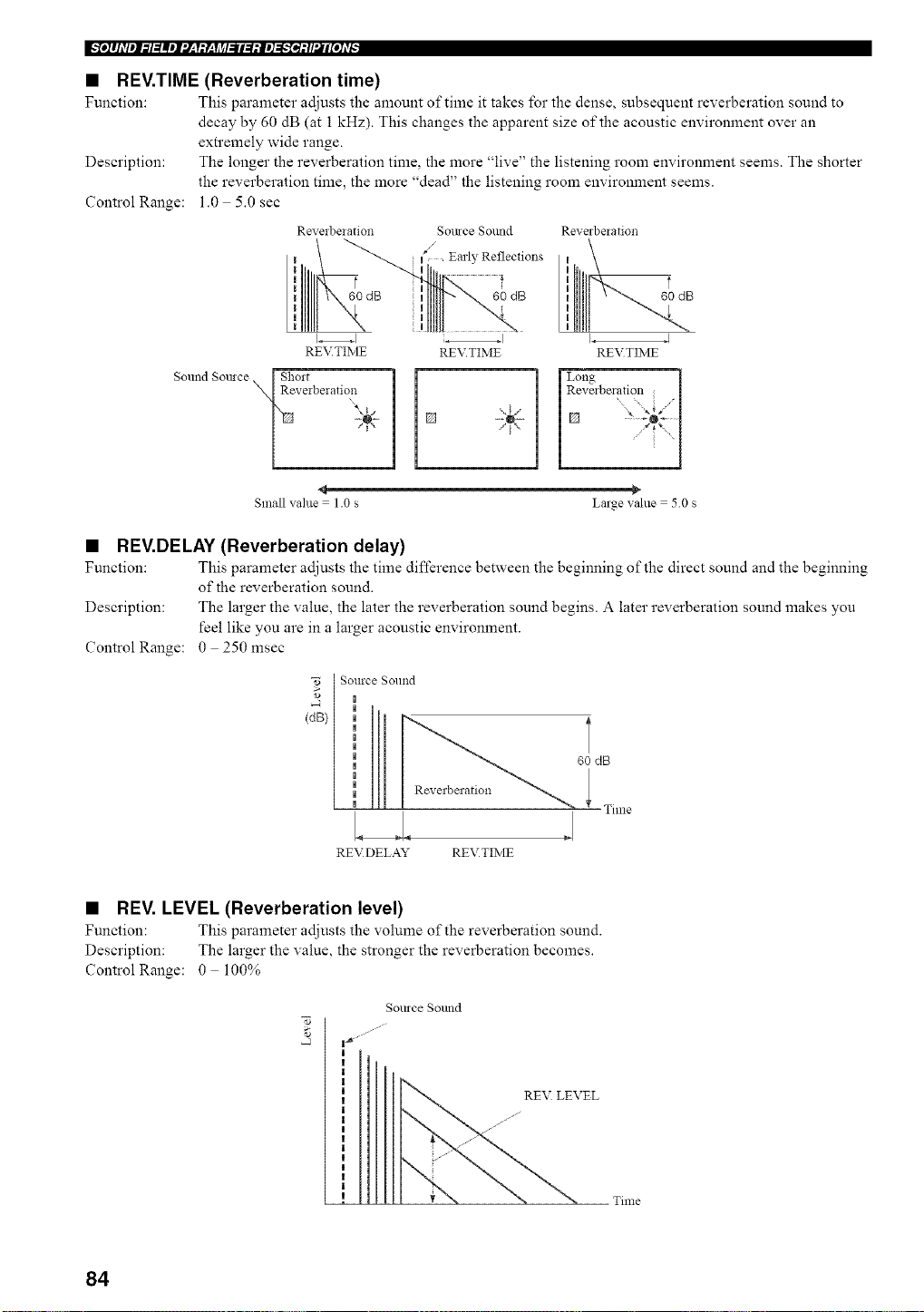
m,.',le]#JdleJf._l=_meJf'.l_,T_y_,Tjff_fi_le]=,_,,.'[ei_ll2#[e]d_
• REV.TIME (Reverberation time)
Function: This parameter adjusts the amount of time it takes for the dense, subsequent reverberation sound to
decay by 60 dB (at 1 kHz). This changes the apparent size of the acoustic environment over an
extremely wide range.
Description: The longer the reverberation time, the more "live" the listening room environment seems. The shorter
the reverberation time, the more "dead" the listening room environment seems.
Control Range: 1.0 5.0 sec
Reverbelation
I
I
,,
,,
I
REVTIME
Sound Somce [ Short
NReveiberatio,n
Somce Sound
/
Earl?, Reflections
uu 60 dB
I
REV.TIME
Reverbelation
L I
REVTIME
Long i
Revmberation l
[]
Small value = 1.0 s Large value = 50 s
• REV.DELAY (Reverberation delay)
Function: This parameter adjusts the time difference between the beginning of the direct sound and the beginning
of the reverberation sound.
Description: The larger the value, the later the reverberation sound begins. A later reverberation sound makes you
feel like you are in a larger acoustic environment.
Control Range: 0 250 msec
[ Source Sound
,o [ |
(dB}
Reverberation
RE\_DELAY REVTIME
60 dB
Time
• REV. LEVEL (Reverberation level)
Function: This parameter adjusts the vohnne of the reverberation sound.
Description: The larger the value, the stronger the reverberation becomes.
Control Range: 0 100%
gollrce Sollnd
__:EL Time
84
_[o]lJdleJ_l:llel'.[:l:Y:li_l_ll:l:ie]_;.'[_:ll'JIi[O]d[
• DIALG.LIFT (Dialog lift)
Function: This parameter adjusts the height of the front and center channel sounds by assigning some of the front
and center channel elements to the presence speakers.
Description: The larger the parameter, the higher the position of the fi'ont and center channel sound.
Choices: 0/1/2/3/4/5, initial setting is 3.
For 7ch Stereo
Function: These parameters adjust the volume level for each channel in 7-channel stereo mode.
ControlRange: 0 100%
• CT LEVEL (Center level)
• SL LEVEL (Surround left level)
• SR LEVEL (Surround right level)
• SB LEVEL (Surround back level)
• PL LEVEL (Presence left level)
• PR LEVEL (Presence right level)
For PRO LOGIC IIx Music and PRO LOGIC II Music
• PANORAMA
Function: Extends the front stereo image to include the surround speakers for a wraparound effect.
Choices: OFF/ON, initial setting is OFF.
• DIMENSION
Function: Gradually adjusts the sound field either towards the l_:ont or towards the rear.
Control range: 3 (towards the rear) to +3 (towards the front), initial setting is STD (standard).
• CENTER WIDTH
Function: Adjusts the center image from all three front speakers to varying degrees. A larger value adjusts the
center image towards the front left and right speakers.
Control range: 0 (center channel sound is output only from center speaker) to 7 (center channel sound is output only
from front left and right speakers), initial setting is 3.
For PRO LOGIC IIx Music, Movie and Game
• PLII/PLIIx (Pro Logic II/Pro Logic IIx)
Function: Switches the type of Pro Logic decoding to be used. PLII decoding creates 5. l-channel sound from 2-
channel sources. PLIIx decoding creates 6.1/7.1-channel sound from 2-channel sources.
Choices: PLII, PLIIx
For DTS Neo:6 Music
• C. IMAGE (Center image)
Function: This parameter adjusts the center image from all three front speakers to varying degrees.
Control range: 0 1.0
For THX Cinema
• DEC (2ch Decoder Select)
Function: Selects the decoder used to playback 2-channel sources using THX Cinema.
Choices: PRO LOGIC / PLII Movie / Neo:6 Cinema
85
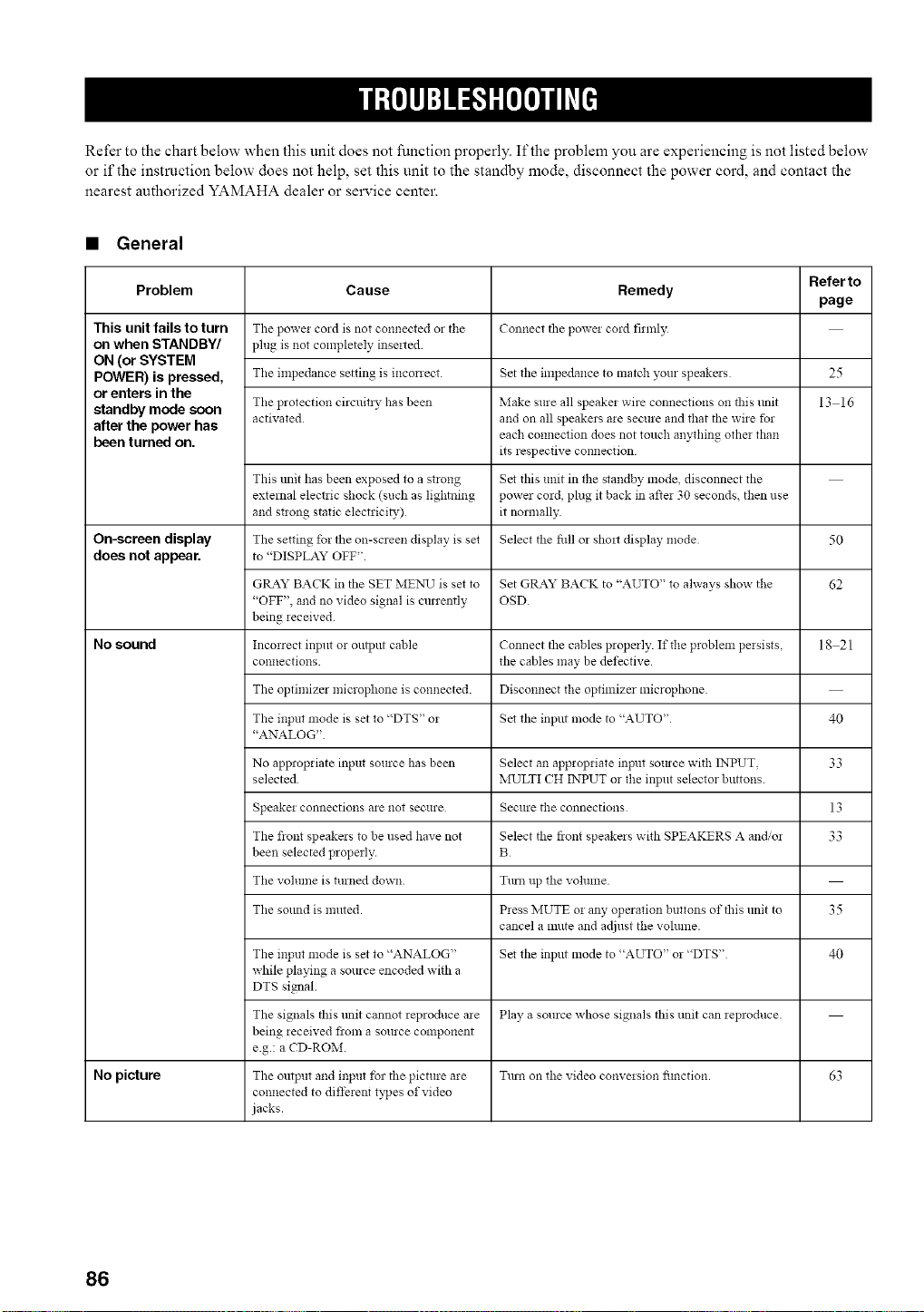
Refer to the chart below when this unit does not function properly. If the problem you are experiencing is not listed below
or if the instruction below does not help, set this unit to the standby mode, disconnect the power cord, and contact the
nearest authorized YAMAHA dealer or service center.
• General
Refer to
Problem Cause Remedy
page
This unit fails to turn The powei co_d is not connected 02 tile Connect the powei cord firmly
on when STANDBY/ plug is not completely inseited
ON (or SYSTEM
POWER) is pressed, Tile impedance setting is mconect. Set tile impedance to match your speakers 25
or enters in the
standby mode soon The protection circuitiy ha s been Make sure all speakei wire connections on this refit 13 16
activated and on all speakers aie secure and that the wire for
after the power has each connection does not touch anything othe: than
been turned on. its respective connection
This unit has been exposed to a StlO!lg Set tilts unit in the standby *node disconnect tile
external electiic shock (such as lightning power cmd, plug it back in aftei 30 seconds, then use
and stwng static electrici_,) it normally
On-screen display The setting for the on-screen display is set Select the fill or shoit display mode 50
does notappear, to "DISPLAYOFF".
GtLa2z" BACK in the SET ME>,qJ is set to Set GRAY BACK to "AUTO" to always show the 62
"OFF", and no video signal is currently OSD
being ,eceived.
No sound Incorrect input or output cable Connect the cables properly. If the problem pe*sists, 18 21
connections, the cables may be defective.
The optimizer microphone is connected. Disconnect the optimizer microphone.
The input mode is set to "DTS" o5 Set the input mode to "AUTO" 40
"ANALOG"
No appropriate input source has been Select an appropriate input somce with INPUT, 33
selected MULTI CH INPUT or the input selector buttons.
Speakm connections are not secure Secure the connections 13
The fiont speakers to be used have not Select the fiont speakers with SPEAKERS A and/or 33
been selected properly. B
The volume is turned down. Turn up the volume
The sound is muted. P*ess NIUTE m any operation buttons of this unit to 35
cancel a mute and adjust the volmne.
r
The input mode is set to "ANALOG" Set the input mode to "AUTO" m "DTS" 40
while playing a source encoded with a
DTS signal
The signals this refit cannot reproduce a*e Play a source whose signals this unit can *eproduce.
being *eceived flora a source component
e.g.: a CD-ROM.
No picture The output and input for the picture are Turn on the video conve,sion fimction. 63
connected to diffment types of video
jacks.
86
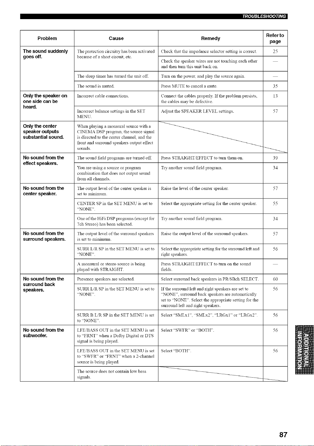
[iPJq:l_'WO';qlff["
Problem
The sound suddenly
goes off.
Only the speaker on
one side can be
heard.
Only the center
speaker outputs
substantial sound.
No sound from the
effect speakers.
No sound from the
center speaker,
No sound from the
surround speakers.
No sound from the
surround back
speakers.
No sound from the
subwoofer.
Refer to
Cause Remedy
page
The protection cilcuitl T has been activated Check that the impedance selecto_ setting is correct 25
becallse of a shmt cirmfit, etc.
Check the speaker wires are not touching each other
and then turn this unP, back on
The sleep timer has lmamd the unit off Turn on tile power, and play the source again
The sound is ranted. Press MUTE to cancel a mute
Inconect cable connections
35
13
Connect the cables properly. If tile problem pmsists,
the cables may be dethctive
Inconect balance settings in the SET Adjust the SPEAKER LEVEL settings. 57
MENU.
When playing a monaural source with a
CINEMA DSP program, the somce simml
is directed to the center channel, and the
fiont and surround speakers outpnt effect
sounds.
The sound field programs are tinned off Press STRAIGHT/EFFECT to turn them on
"_u are using a source or program Tly anothm sound field p_ogram.
combination that does not ontput sound
fiom all channels.
The output level of the center speaker is Raise the level of the cente! speaker
set to lninilllunl.
CENTER SP in the SET MENU is set to Select tile appropriate setting for tile center speaker.
"NONE".
One of the HiFi DSP programs (except tbr Tly anothm sound field program.
7ch Stereo) has been selected.
The oulpnt level of the surround speakers Raise the ontpnt level of tile surrotmd speakers
is set to minimum.
SURR L.'R SP in the SET ME),q.7 is set to
"NONE".
Select the appropriate setting for the surrmmd left and
right speakms
Press STRAIGHT/EFFECT to 111rnon the sound
fields.
Select surround back speakers in PR,'SBch SELECT.
A monanral 02 stereo source is being
played with STRAIGHT.
Presence speakers are selected.
SURR L/R SP in the SET MEN_7 is set to
"NONE".
If the surromld left and right speakers are set to
"NONE", surround back speakers are automatically
set to "NONE" Select the appropriate setting for the
smround left and right speakers.
Select "SMLxt", "SMLx2", "LRGx 1" or "LRGx2"
SURR B LiR SP in the SET MENU is set
to "NONE"
Select "SWFR" or "BOTH".
Select "BOTH".
LFEiBASS OUT in the SET MENX7is set
to "FRNT" when a Dolby Digital or DTS
signal is being played.
LFE'BASS OUT in the SET MEI"O.7is set
to "SWFR" or "FRNT" when a 2-channel
smlrce is being played
The somce does not contain low bass
signals.
39
34
57
55
34
57
56
60
56
56
56
56
87
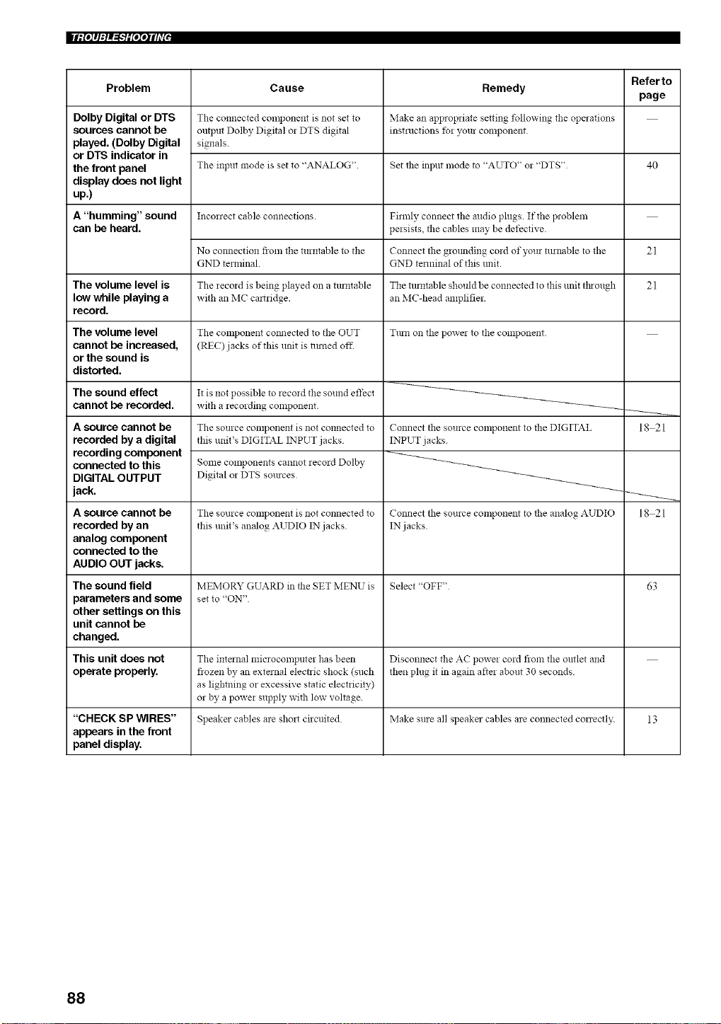
Problem
Dolby Digital or DTS
sources cannot be
played. (Dolby Digital
or DTS indicator in
the front panel
display does not light
up.)
A "humming" sound
can be heard.
The volume level is
low while playing a
record.
The volume level
cannot be increased,
or the sound is
distorted.
The sound effect
cannot be recorded.
A source cannot be
recorded by a digital
recording component
connected to this
DIGITAL OUTPUT
jack.
A source cannot be
recorded by an
analog component
connected to the
AUDIO OUT jacks.
The sound field
parameters and some
other settings on this
unit cannot be
changed.
This unit does not
operate properly.
Cause
The connected component is not set to
output Dolby Digital or DTS digital
signals.
The input mode is set to "ANALOG".
Inconect cable co!lnections.
No connection from tile turntable to tile
GND terminal.
The recoM is being played on a tunltable
with an MC caltridge.
The component com_ected to the OUT
(REC) jacks of this unit is nlmed off.
It is not possible to record the sound effect
with a recording component.
The source component is not connected to
this unit's DIGITAL INPUT jacks
Some components cannot recoM Dolby
Digital or DTS sources
The source component is not connected to
this unit's analog ,aUDIO IN jacks
Remedy
Make an appropriate setting following the opmations
instructions tbr your component
Set the input mode to "AUTO" or "DTS"
Filmly connect the mldio plugs. If the problem
persists, the cables may be detective.
Connect the grounding cord of your nlrnable to the
GND terminal of this unit.
The rotatable should be connected to this unit through
an MC-head amplifier.
Turn on the powel to the component
Connect tile source cmnponent to the DIGITAL
INPUT jacks.
Connect the source COlnponent to the analog AUDIO
IN jacks
Referto
page
40
21
21
MEMORY GUARD in tile SET MENU is Select "OFF" 63
set to "ON"
The internal microcomputer has been Disconnect the AC power cord from the outlet and
flozen by an external electric shock (such then plug it in again after about 30 seconds
as lightning or excessive static electricity)
or by a power supply with low voltage
"CHECK SP WIRES" Speaker cables are sholt circuited Make sure all speakel cables are connected conectl>: 13
appears in the front
panel display.
18 21
18 21
88
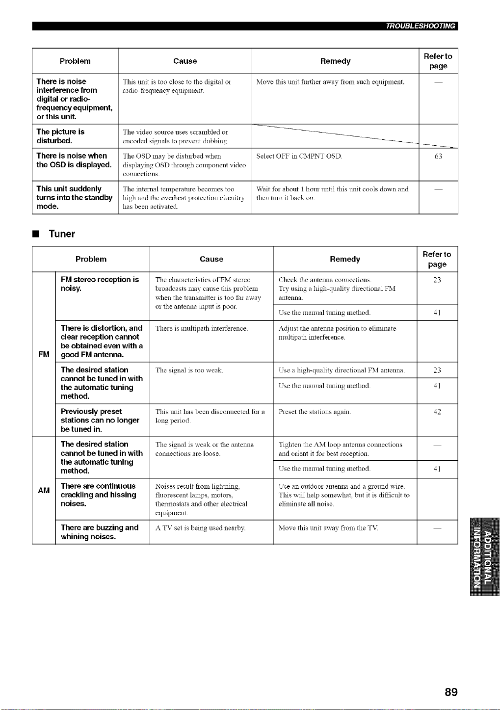
[iP_q:l_"_iP;qlfi'["
Problem
There is noise
interference from
digital or radio-
frequency equipment,
or this unit,
Cause
This unit is too close to the digital o!
radio-fiequency equipment.
Remedy
Move this unit furthe_ away fronl such equipn_ent.
Referto
page
The picture is The video source uses scrambled or
disturbed, encoded signals to prevent dubbing. _-_
There is noise when The OSD may be disturbed when Select OFF in CMPNT OSD 63
the OSD is displayed, displaying OSD through component video
connections.
This unit suddenly The internal tempemlme becomes too Wait t_r about 1 hour until this unit cools down and
turns into the standby high and the overheat protection circuit_ T then turn it back on.
mode. has been activated
• Tuner
Refer to
Problem Cause Remedy
page
FM stereo reception is 23
noisy.
FM
There is distortion, and
clear reception cannot
be obtained even with a
good FM antenna.
The desired station
cannot be tuned in with
the automatic tuning
method.
The characteristics of FM stereo
broadcasts may cause this problem
when tile transmitter is too tar away
or the antenna input is poor.
Check the antenna connections.
T*y using a high-quality directional FM
antenna
Use the mamml tuning mefllod 41
There is multipath interference Adjust the antenna position to eliminate
nmltipath interference
The signal is too weak. Use a high-quality directional FM antenna. 23
Use tile manual tuning mefllod 41
Previously preset This trait has been disconnected tbr a Preset the stations again 42
stations can no longer long period.
be tuned in.
Tile signal is weak or tile antenna
connections are loose.
The desired station
cannot be tuned in with
the automatic tuning
method.
Tighten the AM loop antenna connections
and orient it tbr best reception
Use the mamml tuning method
41
There are continuous Noises result from lightning, Use an outdoor antenna and a ground wire.
AM
crackling and hissing fluorescent lamps, motors, This will help somewhat, but it is difficult to
noises, thermostats and other electrical eliminate all noise
equipment.
There are buzzing and A TV set is being used nearby. Move this unit away flora tile T\I
whining noises.
89
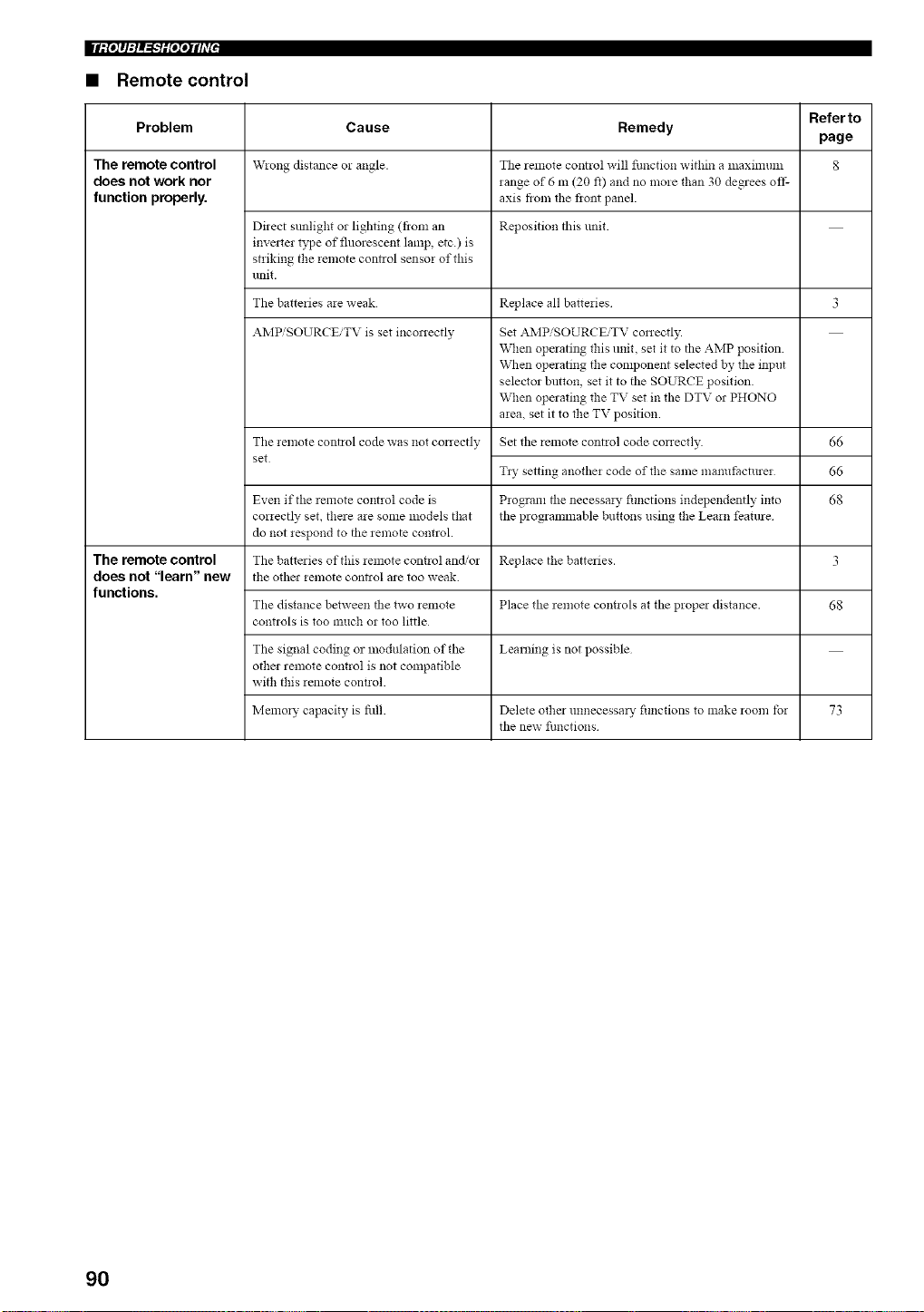
• Remote control
Refer to
Problem Cause Remedy
page
The remote control W!ong distance o! angle. The remote control will function within a lllaxinlunl 8
does not work nor range of 6 m (20 f0 and no more than 30 degrees off-
function properly, axis flora tile fiont panel.
Direct sunlight or lighting (flora an Reposition this unit.
invmter type of fluorescent lamp, etc.) is
striking the remote control sensor of this
unit.
The batteries are weak Replace all batteries 3
AMPiSOURCEiTV is set inconectly Set .aJvIPiSOURCEiTV conectly.
When operating this unit, set it to the AMP position
When operating the component selected by the input
selector button, set it to the SOURCE position
When operating the TV set in the DTV or PHONO
area, set it to the TV position
The remote control code was not conectly Set the remote control code conectly.
set
66
66
68
Tzy setting another code of the same ma*mt=acturer
Even if the remote control code is Program the necessm T fimctions independently into
correctly set, there are some models that the programmable buttons using the Learn feature
do not respond to the remote control.
The remote control The batteries of this remote cozmol and/or Replace the batteries. 3
does not "learn" new the othm remote contzol are too weak.
functions.
The distance between the two _emote Place the _emote cmmols at the propm distance. 68
controls is too much or too little
The signal coding or modulation of the Learning is not possible
other remote control is not compatible
with this remote cont!ol.
Memory capacity is fill. Delete other unnecessm T fimctions to make room tbr 73
the new fimctions
90
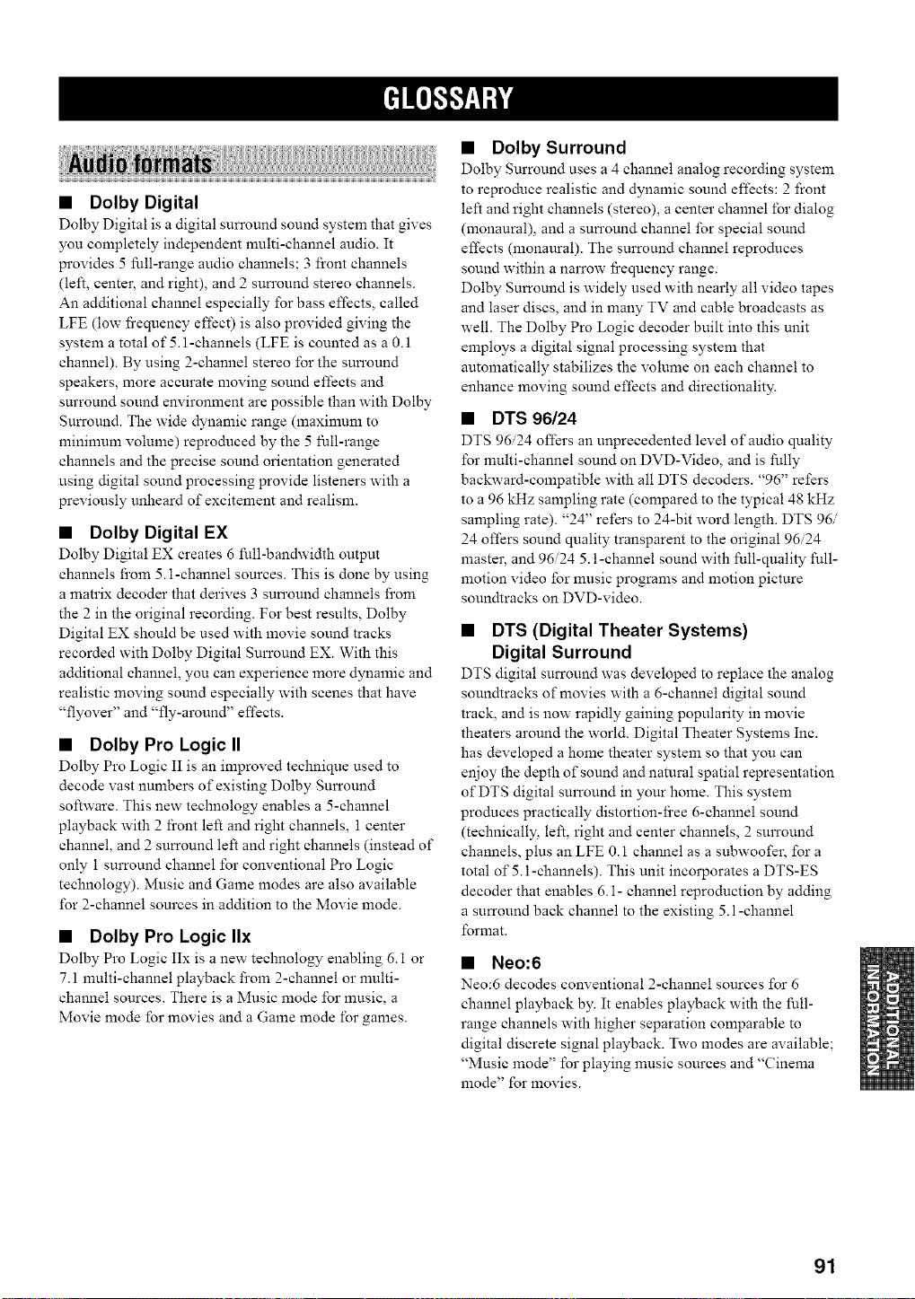
• Dolby Digital
Dolby Digital is a digital surround sound system that gives
you completely independent multi-channel audio. It
provides 5 full-range audio channels; 3 front channels
(left, center, and right), and 2 surround stereo channels.
An additional channel especially for bass effects, called
LFE (low fi'equency effect) is also provided giving the
system a total of 5.1-channels (LFE is counted as a 0.1
channel). By using 2-channel stereo for the surround
speakers, more accurate moving sound effects and
surround sound environment are possible than with Dolby
Surround. The wide dynamic range (maximum to
minimum volume) reproduced by the 5 full-range
channels and the precise sound orientation generated
using digital sound processing provide listeners with a
previously unheard of excitement and realism.
• Dolby Digital EX
Dolby Digital EX creates 6 full-bandwidth output
channels from 5.1-channel sources. This is done by using
a matrix decoder that derives 3 surround channels from
the 2 in the original recording. For best results, Dolby
Digital EX should be used with movie sound tracks
recorded with Dolby Digital Surround EX. With this
additional channel, you can experience more dynamic and
realistic moving sound especially with scenes that have
"flyover" and _'fly-around" effects.
• Dolby Pro Logic II
Dolby Pro Logic II is an improved technique used to
decode vast numbers of existing Dolby Surround
software. This new technology enables a 5-channel
playback with 2 fi'ont left and right channels, 1 center
channel, and 2 surround left and right channels (instead of
only 1 surround channel for conventional Pro Logic
technology). Music and Game modes are also available
for 2-channel sources in addition to the Movie mode.
• Dolby Pro Logic IIx
Dolby Pro Logic IIx is a new technology enabling 6.1 or
7.1 multi-channel playback from 2-channel or multi-
channel sources. There is a Music mode for music, a
Movie mode for movies and a Game mode for games.
• Dolby Surround
Dolby Surround uses a 4 channel analog recording system
to reproduce realistic and dynamic sound effects: 2 front
left and right channels (stereo), a center channel for dialog
(monaural), and a surround channel for special sound
effects (monaural). The surround channel reproduces
sound within a narrow fi'equency range.
Dolby Surround is widely used with nearly all video tapes
and laser discs, and in many TV and cable broadcasts as
well. The Dolby Pro Logic decoder built into this unit
employs a digital signal processing system that
automatically stabilizes the volume on each channel to
enhance moving sound effects and directionality.
• DTS 96/24
DTS 9624 offers an unprecedented level of audio quality
for multi-channel sound on DVD-Video, and is fully
backward-compatible with all DTS decoders. _'96" refers
to a 96 kHz sampling rate (compared to the typical 48 kHz
sampling rate). "24" refers to 24-bit word length. DTS 96/
24 offers sound quality transparent to the original 96/24
master, and 96/24 5.1-channel sound with full-quality full-
motion video for music programs and motion picture
soundtraeks on DVD-video.
• DTS (Digital Theater Systems)
Digital Surround
DTS digital surround was developed to replace the analog
soundtracks of movies with a 6-channel digital sound
track, and is now rapidly gaining popularity in movie
theaters around the world. Digital Theater Systems Inc.
has developed a home theater system so that you can
enjoy the depth of sound and natural spatial representation
of DTS digital surround in your home. This system
produces practically distortion-fi'ee 6-channel sound
(technically, left, right and center channels, 2 surround
channels, plus an LFE 0.1 channel as a subwoofer, for a
total of 5.1-channels). This unit incorporates a DTS-ES
decoder that enables 6.1- channel reproduction by adding
a surround back channel to the existing 5.1-channel
format.
• Neo:6
Neo:6 decodes conventional 2-channel sources for 6
channel playback by. It enables playback with the full-
range channels with higher separation comparable to
digital discrete signal playback. Two modes are available;
"Music mode" for playing music sources and "Cinema
mode" for movies.
91
• PCM (Linear PCM)
Linear PCM is a signal format under which an analog
audio signal is digitized, recorded and transmitted without
using any compression. This is used as a method of
recording CDs and DVD audio. The PCM system uses a
technique fbr sampling the size of the analog signal per
very small unit of time. Standing for "pulse code
modulation", the analog signal is encoded as pulses and
then modulated for recording.
• CINEMA DSP
Since the Dolby Surround and DTS systems were
originally designed for use in movie theaters, their effect
is best felt in a theater having many speakers and designed
for acoustic effects. Since home conditions, such as room
size, wall material, nmnber of speakers, and so on, can
differ so widely, it's inevitable that there are differences in
the sound heard. Based on a wealth of actually measured
data, YAMAHA CINEMA DSP uses YAMAHA original
sound field technology to combine Dolby Pro Logic,
Dolby Digital and DTS systems to provide the visual and
audio experience of a movie theater in the listening room
of your own home.
• SILENT CINEMA
YAMAHA has developed a natural, realistic sound effect
DSP algorithm for headphones.
Parameters for headphones have been set for each sound
field so that accurate representations of all the sound field
programs can be enjoyed on hea@hones.
• Virtual CINEMA DSP
YAMAHA has developed a Virtual CINEMA DSP
algorithm that allows you to enjoy DSP sound field
surround effects without any surround speakers by using
virtual surround speakers.
It is even possible to enjoy Virtual CINEMA DSP using a
minimal two-speaker system that does not include a center
speaker.
92
• ITU-R
ITU-R is the radio communication sector of the ITU
(Intemational Telecommunication Union). ITU-R
recommends a standard speaker placement which is used
in many critical listening rooms, such as mastering
studios.
• LFE 0.1 channel
This channel is for the reproduction of low bass signals.
The fi'equency range for this channel is 20 Hz to 120 Hz.
This channel is counted as 0.1 because it only enforces a
low frequency range compared to the full-range
reproduced by the other 5/6 channels in Dolby Digital or
DTS 5.1/6.i-channel systems.
• Sampling frequency and number of
quantized bits
When digitizing an analog audio signal, the number of
times the signal is sampled per second is called the
sampling frequency_ while the degree of fineness when
converting the sound level into a numeric value is called
the number of quantized bits.
The range of rates that can be played back is determined
based on the sampling rate, while the dynamic range
representing the sound level difference is determined by
the number of qnantized bits. In principle, the higher the
sampling frequency, the wider the range of frequencies
that can be played back, and the higher the number of
quantized bits, the more finely the sound level can be
reproduced.
qip,l"i_',lfill"I
• THX Cinema processing
THX is an exclusive set of standards and technologies
established by the world-renowned film production
company, Lucasfilm Ltd. THX grew from George Lucas'
personal desire to make your experience of the film
soundtrack, in both movie theatres and in your home
theatre, as _aithful as possible to what the director
intended.
Movie soundtracks are mixed in special movie theatres
called clubbing stages and are designed to be played back
in movie theatres with similar equipment and conditions.
This same soundtrack is then transferred directly onto
Laserdise, VHS tape, DVD, etc., and is not changed for
playback in a small home theatre environment.
THX engineers developed patented technologies to
accurately translate the sound from the movie theatre
environment into the home, correcting the tonal and
spatial errors that occur. On this product, when the THX
indicator is on, THX features are automatically added in
Cinema modes (e.g. THX Cinema, THX Surround EX).
Adaptive decorrelation
In a movie theatre, a large number of surround speakers
help create an enveloping surround sound experience, but
in a home theatre there are usually only two speakers. This
can snake the surround speakers sound like hea@hones
that lack spaciousness and envelopment. The surround
sounds will also collapse into the closest speaker as you
move away from the middle seating position. Adaptive
decorrelation slightly changes one surround channel's time
and phase relationship with respect to the other surround
channel. This expands the listening position and creates
with only two speakers the same spacious surround
experience as in a movie theatre.
Re-equalization
The tonal balance of a film soundtrack will be excessively
bright and harsh when played back over audio eqnipment
in the home because film soundtracks were designed to be
played back in large movie theatres using very different
professional equipment. Re-equalization restores the
correct tonal balance for watching a movie soundtrack in a
small home environment.
Timbre matching
The human ear changes our perception of sound
depending on the direction fi'om which it is coming. In a
movie theatre, there is an array of surround speakers so
that the surround information is all around you. In a home
theatre, you use only two speakers located to the side of
your head. The timbre matching feature filters the
information going to the surround speakers so that they
snore closely snatch the tonal characteristics of the sound
coming from the fi'ont speakers. This ensures seamless
panning between the front and surround speakers.
93
• THX Select
Before any home theatre component can be THX Select
certified, it must incorporate pass a rigorous series of
quality and perlbnnance tests. Only then can a product
feature the THX Select logo, which is your guarantee that
the Home Theatre products you purchase will give you
superb performance for many years to come. THX Select
requirements cover every aspect of the product including
power amplifier and pre-amplifier perlbrmance and
operation, and hundreds of other parameters in both the
digital and analog domain.
• THX Surround EX
THX Surround EX - Dolby Digital Surround EX is a joint
development of Dolby Laboratories and the THX Ltd.
In a movie theater, film soundtracks that have been
encoded with Dolby Digital Surround EX technology are
able to reproduce an extra channel which has been added
during the mixing of the program. This channel, called
Surround Back, places sounds behind the listener in
addition to the currently available front left, front center,
front right, surround right, surround left and subwoofer
channels. This additional channel provides the opportunity
for more detailed imaging behind the listener and brings
more depth, spacious ambience and sound localization
than ever before.
Movies that were created using the Dolby Digital
Surround EX technology, when released into the home
consumer market may exhibit wording to that effect on the
packaging. A list of movies created using this technology
can be found on the Dolby web site at www.dolby.com. A
list of available DVD software titles encoded with this
technology can be found at www.thx.com.
Only receiver and controller products bearing the THX
Surround EX logo, when in the THX Surround EX mode,
_aithfully reproduce this new technology in the home.
This product may also engage the THX Surround EX
mode during the playback of 5.1 channel material that is
not Dolby Digital Surround EX encoded. In such cases the
information delivered to the Surround Back channel will
be program dependent and may or may not be pleasing
depending on the particular soundtrack and the tastes of
the individual listener.
• Component video signal
With the component video signal system, the video signal
is separated into the Y signal for the luminance and the PB
and Pa signals for the chrominance. Color can be
reproduced more faithfully with this system because each
of these signals is independent. The component signal is
also called the "color difference signal" because the
luminance signal is subtracted from the color signal.
A monitor with component input jacks is required in order
to use the component signal for output.
• Composite video signal
With the composite video signal system, the video signal
is composed of three basic elements of a video picture;
color, brightness and synchronization data. A composite
video jack on a video component transmits these three
elements combined.
• S-video signal
With the S-video signal system, the video signal normally
transmitted using a pin cable is separated and transmitted
as the Y signal for the luminance and the C signal for the
chrominance through the S-video cable. Using the S
VIDEO jack eliminates video signal transmission loss and
allows recording and playback of even more beautiful
images.
94
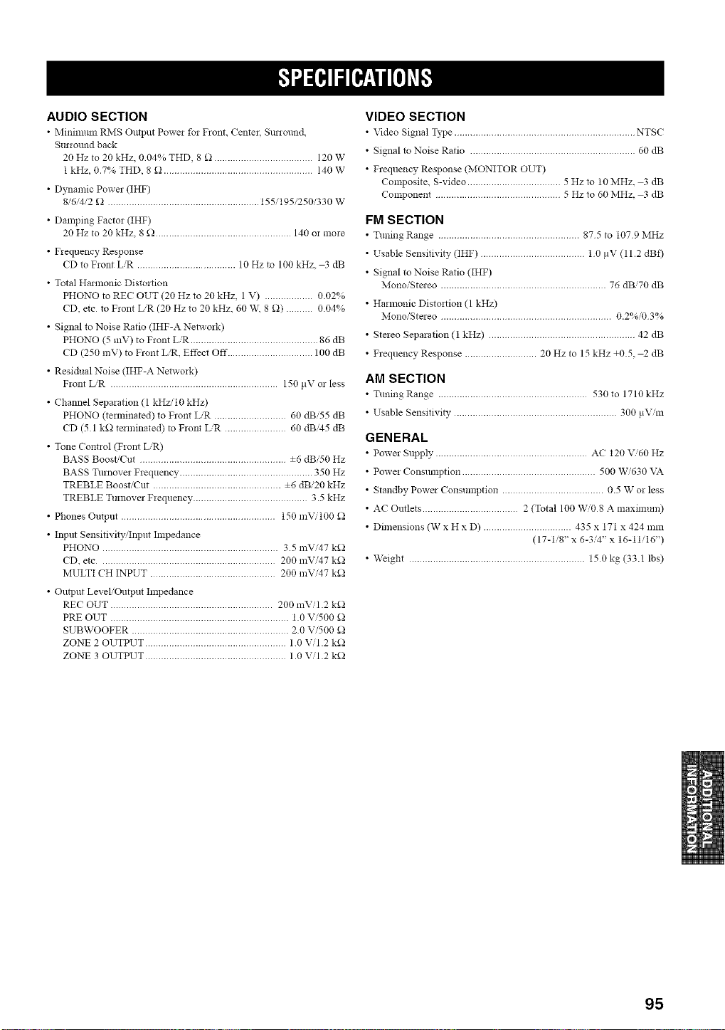
AUDIO SECTION
• Minmmm RNIS Output Powe! for Front, Center, SmTound
Surround back
20 Hz to 20 kHz, 004% THD, 8 _ ..................................... 120 W
1 kHz, 0.7% THD, 8 _ ........................................................ 140 W
• Dynamic Power (IHF)
8/6/4,'2 _ ......................................................... 155/195/250/330 W
• Damping Factor (IHF)
20 Hz to 20 kHz, 8 _ ................................................... 140 or more
• Frequency Response
CD to Front LiR ..................................... 10 Hz to 100 kHz, 3 dB
• Total Hannonic Distortion
PHONO to REC OUT (20 Hz to 20 kHz, 1 V) .................. 0.02%
CD, etc to Front LiR (20 Hz to 20 kHz, 60 W\ 8 £)) .......... 0.04%
• Signal to Noise Ratio (IHF-A Network)
PHONO (5 mV) to Front LiR ................................................ 86 dB
CD (250 mV) to Front L/R, Effect Off ................................ 100 dB
• Residual Noise (IHF-A Network)
Front LiR ............................................................... 150 ltV or less
• Channel Separation (1 kHzi10 kH7)
PHONO 0emfinated) to Front L/R ........................... 60 dBi55 dB
CD (51 k£_ terminated) to Front L,'R ....................... 60 dB'45 dB
• Tone Control (Front L/R)
BASS Boost/Cut ....................................................... ±6 dBi50 Hz
BASS Turnover Frequency .................................................. 350 Hz
TREBLE Boost/Cut ................................................ ±6 dBi20 kHz
TREBLE Turnover Frequency ........................................... 3.5 kHz
• Phones Output .......................................................... 150 mVi100 _)
• Input Sensitivity,'Input Impedance
PHONO .................................................................. 3.5 mVi47 k_
CD, etc .................................................................. 200 mVi47 k_
MULTI CH INPUT ............................................... 200 mVi47 k_
• Output Level/Output hnpedance
REC OUT ............................................................. 200 mVil.2 k£_
PRE OUT ................................................................... 1.0 Vi500 _
SUBWOOFER ........................................................... 2.0 Vi500 _
ZONE 2 OUTPUT ..................................................... 1.0 Vii .2 k£_
ZONE 3 OUTPUT ..................................................... 1.0 Vii .2 k£_
VIDEO SECTION
• Video Signal Type .................................................................... NTSC
• Signal to Noise Ratio .............................................................. 60 dB
• Frequency Response (MONITOR OUT)
Composite, S-video ................................... 5 Hzto 10MHz, 3 dB
Component ............................................... 5 Hz to 60 MHz, 3 dB
FM SECTION
• Tuning Range ..................................................... 875 to 1079 IMHz
• Usable Sensitivity (IHF) ....................................... 1 0 tlV (11.2 dBf)
• Signal to Noise Ratio (IHF)
Mono/Stereo .............................................................. 76 dBi70 dB
• Harmonic Disto!fion (1 kHz)
Mono/Stereo ................................................................ 0.2%/03%
• Stereo Separation (1 kHz) ....................................................... 42 dB
• Frequency Response ........................... 20 Hz to 15 kHz +0.5, _ dB
AM SECTION
• Tuning Range ........................................................ 530 to 1710 kHz
• Usable Sensitivi_, ............................................................. 300 ltVim
GENERAL
• Power Supply ......................................................... AC 120 V,'60 Hz
• Power Consumption .................................................. 500 W/630 VA
• Standby Power Consumption ...................................... 0.5 W or less
• AC Outlets .................................... 2 (Total 100 Wi08 A maximum)
• Dimensions (W x H x D) ................................. 435 x 171 x 424 mm
(17-1/8" x 6-34" x 16-11/16")
• Weight .................................................................. 150 kg (33.1 lbs)
95
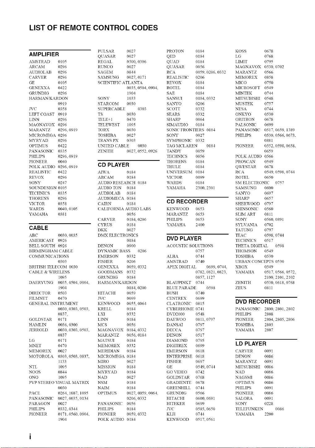
LIST OF REMOTE CONTROL CODES
PULSAR 0027
AMPLIFIER QUASAR 0027
AMSTRAD 0105 REGAL 0300, 0306
ARCAM 0296 RUNCO 0027
AUDIOLAB 0296 SAGEM 0844
CARVER 0296 SAMSELNG 0027, 0171
GE 0105 SCIENTIFIC ATLANTA
GENEXXA 0422 0035, 0504. 0904.
GRLTIDIG 0296 1904
HARMANiKARDON SONY 1033
0919 STAR( OM 0030
JVC 0358 SUPERCABLE 0303
LEFT COAST 0919 TS 0030
LINN 0296 TELE+ 1 0470
MAGNAVOX 0296 TELEWEST 1095
MAP_a.NTZ 0296, 0919 TORX 0030
MIC ROMEGA 0296 TOSHIBA 0027
MYRYAD 0296 TRANS PX 0303
OPTIMUS 0422 ELNITED CABLE 0030
PANASONIC 0335 ZENITH 0027, 0552, 0926
PHILIPS 0296, 0919
PIONEER 0040
POLK AUDIO 0296,0919
REALISTIC 0422
REVOX 0296
SONY 0247
SOUNDESIGN 0105
TECHNICS 0335
THORENS 0296
VICTOR 0358
WARDS 0040, 0105
YAMAHA 038I
CABLE
ABC 0030 0035
AMERICAST 0926
BELL SOUTH 0926
BIRMINGHAM CABLE
COMME'NICATIONS
0303
BRITISH TELECOM 0030
CABLE & WIRELESS
1095
DAERYLLNG 0035, 0504, 0904,
1904
DIRECTOR 0503
FILiVINET 0470
GENERAL INSTRUMENT
0030, 0303, 0503,
0837,
GOLDSTAR 0171
HAMLIN 0036, 0300
JERROLD 0030, 0303, 0503,
0837
LG 0171
MNET 0470
MEMOREX 0027
MOTOROLA 0303, 0503, 0837,
1133
NTL 1095
NOOS 0844
ONO 1095
PVP STEREO VISUAL MATRIX
0030
PACE 0264, 1087, 1095
PANASONIC 0027. 0035. 0134
PARAGON 0027
PHILIPS 0332, 0344
PIONEER 017t, 0560, 0904,
t904
CD PLAYER
AIWA 0184
ARCAM 0 t 84
AUDIO RESEARCH 0184
AUDIO TON 0184
AUDIOLAB 0184
AUDIOMECA 0184
CAIRN 0 t 84
CALIFORNIA AUDIO LABS
0056
CARVER 0 t 84, 0206
CYRUS 0184
DKK 0027
DMX ELECTRONICS
0184
DENON 0900
D'*2qAMIC BASS 0206
EMERSON 0332
FISHER 0206
GENEXXA 0059, 0332
GOODMANS 0332
GRUNDIG 0184
HARMAN, KARDON
0184, 0200
HITACHI 0059
JV( 0099
KENWOOD 0055, 0064
KRELL 0184
LXI 0332
LINEN 0184
MCS 0056
MAGNAVOX 0t84, 0332
MARANTZ 0056, 0184
MATSUI 0184
MEMOREX 0332
MERIDIAN 0184
MICROMEGA 0t84
MIRO 0027
MISSION 0184
MYRYAD 0 t 84
NAD 0027
NSM 0184
NAIM 0 t 84
OPTIMUS 0027, 0059, 0064.
0206, 0332
PANASONIC 0056
PHILIPS 0184
PIONEER 0059, 0332
POLK AUDIO 0184
PROTON 0184
QED 0t84
QUAD 0184
QUASAR 0056
RCA 0059. 0206. 0332
REALISTIC 0206
REVOX 0184
ROTEL 0184
SAE 0184
SANSUI 0184. 0332
SA_Nryo 0206
SCOTT 0332
SEARS 0332
SHARP 0064
SIMAUDIO 0184
SONIC FRONTIERS 0184
SONY 0027
SYMPHONIC 0332
TAG MCLAREN 0184
TANDY 0059
TECHNICS 0056
THORENS 0184
THULE 0184
UNIVERSUM 0184
VICTOR 0099
WARDS 0184
YAMAHA 2300. 230I
CD RECORDER
KENWOOD 0653
MARANTZ 0653
PHILIPS 0653
YAMAHA 2400
DVD PLAYER
ACOUSTIC SOLUTIONS
0757
ALBA 0744
AMSTRAD 0740
APEX DIGITAL 0699. 0744.
0782. 0821, 0823.
0857, 1127
BLAUPINKT 0744
BLUE PARADE 0598
BUSH 0740
CENTREX 0699
CLATRONIC 0815
CYBERHOME 0741
DVD2000 0548
DAETVOO 0811. 0797
DANSAI 0797
DECCA 0797
DENON 0517
DIAMOND 0795
DIGITREX 0699
EMERSON 0618
ENTERPRISE 0618
FISHER 0697
GE 0549, 0744
GO VIDEO 0742
GOLDSTAR 0768
GRADIENTE 0678
GREENHILL 0744
GRLLNDIG 0566
HITACHI 0600, 0691
HITEKER 0699
JVC 0585, 0650
KLH 0744
KENWOOD 0517. 056t
KOSS 0678
LG 0768
LIMIT 0795
MAGNAVOX 0530, 0702
MAIL4NTZ 0566
MEMOREX 0858
MI(O 0750
MICROSOFT 0549
MINTEK 0744
MITSUBISHI 0548
MUSTEK 0757
NESA 0744
ONKYO 0530
ORITRON 0678
PALSONI( 0699
PANASONIC 0517. 0659. 1389
PHILIPS 0530. 0566. 0673.
0881
PIONEER 0552, 0598. 0658.
0659
POLK AUDIO 0566
PROSCAN 0549
QWESTAR 0678
RCA 0549, 0598. 0744
ROTEL 0650
SM ELECTRONIC 0757
SAMSUNG 0600
SANYO 0697
SHARP 0657
SHERWOOD 0797
SHINSONIC 0560
SLIM ART 081t
SONY 0560, 0891
SYLVANIA 0702
TATUNG 0797
TEA( 0598, 0744
TECHNICS 0517
THETA DIGITAL 0598
THOMSON 0549
TOSHIBA 0530
URBAN CONCEPTS 0530
XBOX 0549
YAMAHA 0517, 0566. 0572.
2100, 2101.2t02
ZENITH 0530, 0618. 0768
ZEUS 081 t
DVD RECORDER
PANASONIC 2800. 2801. 2802
PHILIPS 2808
PIONEER 2804, 2805. 2806
TOSHIBA 2803
YAMAHA 2807
LD PLAYER
CARVER 0091
DENON 0086
MARANTZ 0091
MITSUBISHI 0086
NAD 0086
NAGSMI 0086
OPTIMUS 0086
PHILIPS 0091
PIONEER 0086
SALORA 009 t
SONY 0228
TELEFLLNKEN 0086
YAMAHA 2200
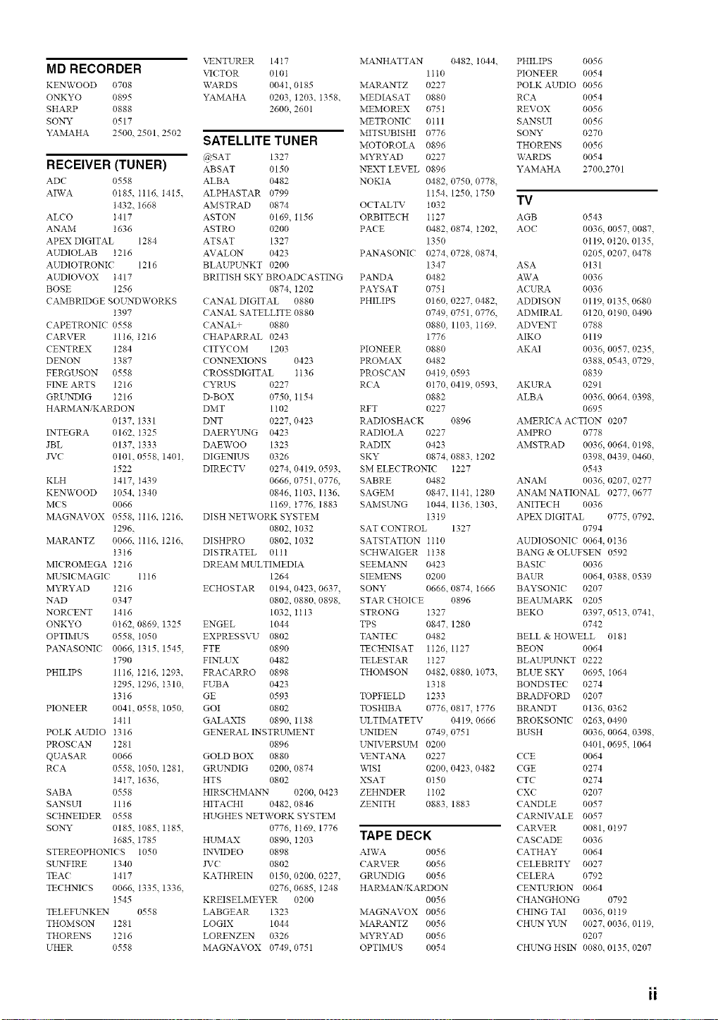
MD RECORDER
KENWOOD 0708
ONKYO 0895
SHARP 0888
SONY 0517
YAMAHA 2500. 2501. 2502
RECEIVER (TUNER)
ADC 0558
AFvVA 0185. I116. 1415.
1432. 1668
ALCO t417
ANAM 1636
APEX DIGITAL 1284
AUDIOLAB t216
AUDIOTRONIC 1216
AUDIOVOX t417
BOSE 1256
CAMBRIDGE SOELNDWORKS
1397
CAPETRONIC 0558
CARVER 1116, 1216
CENTREX 1284
DENON 1387
FERGUSON 0558
FINE ARTS 1216
GRUN_)IG 1216
HARMAN, KARDON
0137. 1331
INTEGRA 0162, I325
JBL 0137, I333
JVC 0101, 0558. 140t,
1522
KLH 1417, I439
KENWOOD 1054. I340
MCS 0066
MAGNAVOX 0558, Ii16. 1216.
1296.
MARANTZ 0066. I116. 1216.
t3t6
MI( ROMEGA t216
MUSIC MAGIC 1116
MYRYAD 1216
NAD 0347
NORCENT 1416
ONKYO 0162, 0869. 1325
OPTIMUS 0558. 1050
PANASONI( 0066. 1315. 1545,
1790
PHILIPS 11t6, t216. I293.
1295. 1296, I310.
1316
PIONEER 0041, 0558. 1050,
1411
POLK AUDIO I316
PROS( AN I281
QUASAR 0066
RCA 0558, I050. 128t,
1417. 1636,
SABA 0558
SANSUI 11 t 6
SCHNEIDER 0558
SONY 0185, 1085. 1185,
1685. 1785
STEREOPHONIC S 1050
SELNFIRE 1340
TEA( 1417
TECHNICS 0066. 1335. 1336,
t545
TELETL2",_KEN 0558
THOMSON 1281
THORENS I216
UHER 0558
VENTURER 1417
VICTOR 0101
WARDS 004I, 0185
YAMAHA 0203, 1203. 1358.
2600, 2601
SATELLITE TUNER
@SAT 1327
ABSAT 0150
ALBA 0482
ALPHASTAR 0799
AMSTRAD 0874
ASTON 0169, 1156
ASTRO 0200
ATSAT 1327
AVALON 0423
BLAUPUNKT 0200
BRITISH SKY BROADCASTING
0874, I202
CANAL DIGITAL 0880
CANAL SATELLITE 0880
CANAL_ 0880
CHAPARRAL 0243
CITYCOM 1203
CO_EXIONS 0423
CROSSDIGITAL It36
CYRUS 0227
D-BOX 0750, 1154
DMT 1 t02
DNT 0227, 0423
DAERYL _rNG 0423
DAEWOO 1323
DIGENIUS 0326
DIRECTV 0274, 0419. 0593
0666, 0751 0776,
0846, I103. 1136.
1169, 1776. 1883
DISH NETWORK SYSTEM
0802, I032
DISHPRO 0802, I032
DISTRATEL 011I
DREAM MULTIMEDIA
1264
ECHOSTAR 0194, 0423 0637.
0802, 0880, 0898,
1032, It13
ENGEL 1044
EXPRESSVU 0802
FTE 0890
FINLUX 0482
FRACARRO 0898
FUBA 0423
GE 0593
GOI 0802
GALAXIS 0890, t138
GENERAL INSTRUMENT
0896
GOLD BOX 0880
GRUNDIG 0200, 0874
HTS 0802
HIRSCHMANN 0200, 0423
HITACHI 0482, 0846
HUGHES NETWORK SYSTEM
0776, 1169. 1776
HUMAX 0890, I203
INVIDEO 0898
JVC 0802
KATHREIN 0150, 0200, 0227.
0276, 0685, 1248
KREISELMEYER 0200
LABGEAR 1323
LOGIX 1044
LORENZEN 0326
MAGNAVOX 0749, 0751
MANHATTAN 0482. 1044.
1tt0
MARANTZ 0227
MEDIASAT 0880
MEiVIOREX 0751
METRONIC 0 t t 1
MITSUBISHI 0776
MOTOROLA 0896
MYRYAD 0227
NEXT LEVEL 0896
NOKIA 0482, 0750, 0778,
1154. 1250, I750
OCTALTV 1032
ORBITECH t t 27
PACE 0482. 0874, I202.
1350
PANASONIC 0274. 0728, 0874.
1347
PANDA 0482
PAYSAT 0751
PHILIPS 0160, 0227, 0482.
0749, 0751, 0776,
0880, 1103, I169.
1776
PIONEER 0880
PROM_%X 0482
PROSCAN 04t9, 0593
RCA 0170. 0419, 0593.
0882
RET 0227
RADIOSHACK 0896
RADIOLA 0227
RADIX 0423
SKY 0874. 0883, 1202
SM ELECTRONIC t227
SABRE 0482
SAGEM 0847, 114I, 1280
SAMSL_rNG 1044. 1136, I303,
1319
SAT CONTROL 1327
SATSTATION Ilt0
SCHYVAIGER It38
SEEMANLN 0423
SIEiVIENS 0200
SONY 0666. 0874, 1666
STAR CHOICE 0896
STRONG 1327
TPS 0847. 1280
TANTEC 0482
TECHNISAT 1126, 1127
TELESTAR t t 27
THOMSON 0482, 0880, I073.
1318
TOPFIELD 1233
TOSHIBA 0776. 0817, 1776
ULTIMATETV 0419. 0666
LLNIDEN 0749, 0751
LLNIVERSUM 0200
VENTANA 0227
\x,qSI 0200, 0423, 0482
XSAT 0150
ZEHNDER 1102
ZENITH 0883, 1883
TAPE DECK
AIWA 0056
CARVER 0056
GRUNDIG 0056
HARiVIANiKARDON
0056
MAGNAVOX 0056
MARANTZ 0056
MYRYAD 0056
OPTIMUS 0054
PHILIPS 0056
PIONEER 0054
POLK AUDIO 0056
RCA 0054
REVOX 0056
SANSUI 0056
SONY 0270
THORENS 0056
WARDS 0054
YAMAHA 2700.2701
TV
AGB 0543
AOC 0036. 0057, 0087,
0119. 0120. 0135,
0205. 0207, 0478
ASA 0131
AWA 0036
ACURA 0036
ADDISON 0119, 0135, 0680
ADMIRAL 0t20, 0190. 0490
ADVENT 0788
AIKO 0119
AKAI 0036. 0057, 0235,
0388, 0543, 0729,
0839
AKURA 0291
ALBA 0036, 0064, 0398,
0695
AMERICA ACTION 0207
AMPRO 0778
AMSTRAD 0036, 0064, 0198,
0398. 0439, 0460,
0543
ANAM 0036. 0207. 0277
ANAM NATIONAL 0277,0677
ANITEC H 0036
APEX DIGITAL 0775, 0792,
0794
AUDIOSONIC 0064. 0t36
BANG & OLUFSEN 0592
BASIC 0036
BAUR 0064. 0388. 0539
BAYSONIC 0207
BEAUMARK 0205
BEKO 0397, 0513, 074t,
0742
BELL & HOWELL 0181
BEON 0064
BLAUPUNKT 0222
BLUE SKY 0695, 1064
BONDSTEC 0274
BRADFORD 0207
BRANDT 0136. 0362
BROKSONIC 0263, 0490
BUSH 0036, 0064, 0398,
0401. 0695, 1064
CCE 0064
CGE 0274
CTC 0274
CXC 0207
CANDLE 0057
CARNIVALE 0057
CARVER 0081, 0197
CASCADE 0036
CATHAY 0064
CELEBRITY 0027
CELERA 0792
CENTURION 0064
CHANGHONG 0792
CHING TAI 0036, 0 t 19
CHE _rNYI-_rN 0027. 0036. 0119,
0207
CHE_G HSIN 0080. 0135, 0207
ii
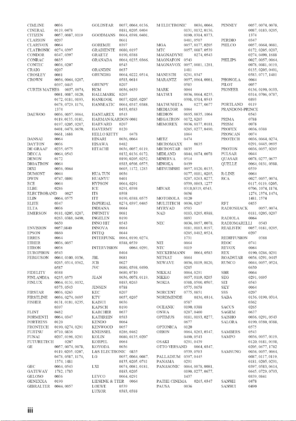
CIMLINE 0036
CINERAL 0119, 0478
CITIZEN 0057, 0087. 0119
CLARION 0207
CLARIVOX 0064
CLATRONIC 0274, 0397
CONDOR 0347, 0397
CONIL_C 0835
CONTEC 0036, 0207
CRAIG 0207
CROSLEY 008t
CROV_rN 0036, 0064. 0207,
0397, 0445
CURTIS MATHES 0057, 0074,
0081, 0087. 0120,
0172, 0181, 0193,
0478, 0729. 1174,
t374
DAEWOO 0036, 0057. 0064,
0119. 0135. 018I,
0197, 0205. 0207,
0401, 0478. 0650,
0661, I688
DANSAI 0064
DAYTON 0036
DE GRAAF 0235, 0575
DECCA 0064, 0543
DENON 0172
DIGATRON 0064
DIXI 0036, 0064
DUMONT 0044
DWIN 0747, 0801
ECE 0064
ELBE 0286
ELEC TROBAND 0027
ELIN 0064, 0575
ELITE 0347
ELTA 0036
EMERSON 018I, 0205, 0207,
0263, 0388. 0490,
0650
EN_'ISION 0057,0840
EPSON 0860
ERRES 0064
ETHER 0036, 0057
ETRON 0036
EUROPHON 0543
FERGUSON 0064, 0100. 0136,
0265, 0314. 0362,
0587
FIDELITY 0388
FINLANDIA 0235, 0373
FINLUX 0064, 0131. 0132.
0373, 0543
FIRSTAR 0036, 0263
FIRSTLINE 0036, 0274. 0695
FISHER 0131, 0181. 0235,
0397
FLINT 0482
FORMENTI 0064, 0347
FORTRESS 0120
FRONTEC H 0190, 0274. 0291
FUJITSU 0710, 0836
FL _rNAI 0207, 0t98. 0291
FUTURETECH 0207
GE 0057, 0074. 0078.
0119. 0205. 0207,
0478, 0587. 1174,
1374, I481
GEC 0064, 0543
GATEWAY 1782, 1783
GELOSO 0036
GENEXXA 0190
GIBRALTER 0044, 0057
GOLDSTAR 0057, 0064, 0136.
0181, 0205. 0404
GOODMANS 0064, 0398, 0401.
0661
GOREMJE 0397
GRADIENTE 0080, 0197
GRAETZ 0190, 0388
GRANADA 0064, 0235, 0366.
0543
GRANDIN 0637
GRL'NDIG 0064, 0222, 0514.
0583, 0614
GRUNPY 0207
HCM 0036, 0439
HALLMARK 0205
HANKOOK 0057, 0205, 0207
HANSEATIC 0064, 0347, 0388.
0455, 0583
HANTAREX 0543
HARMANiKARDON 0081
HARVARD 0207
HAVERMY 0 t 20
HELLO KITTY 0478
HINARI 0036, 0064
HISAWA 0482
HITACHI 0036, 0057, 0119,
0132, 0136. 0172.
0190, 0205, 0252.
0383, 0508. 0575.
0605, t172, I283
HUA TUN 0036
HUANYU 0401
HYPSON 0064, 029t
ICE 0291, 0398
ITS 0398
ITT 0190, 0388, 0575
IMPERIAL 0274, 0397, 0445
INDIANA 0064
INFINITY 0081
INGELEN 0190
IN_'NOHIT 0543
INNOVA 0064
INTEQ 0044
INTERFLrNK 0064, 0190, 0274.
0388, 0539
INTERVISION 0064. 0291,
0404
JBL 0081
JCB 0027
JVC 0080, 0398, 0490.
0680, 0710
JEAN 0036, 0078, 0119.
0183, 0263
JENSEN 0788
KEC 0207
KTV 0057, 0207
KAISUI 0036
KAPSCH 0190
KARC HER 0637
KATHREIN 0583
KENDO 0064
KENWOOD 0057
KNEISSEL 0286, 0462
KOLIN 0080, 0135, 0207
KORPEL 0064
KOYODA 0036
L&S ELECTRONIC? 0835
LG 0057, 0064, 0087.
0135, 0205. 0741
LXI 0074, 008I, 0181.
0183, 0205
LEYCO 0064. 0291
LIESENK & TTER 0064
LOEWE 0539
LUXOR 0383, 0388
M ELECTRONIC 0036, 0064,
0131, 0132, 0136.
0190. 0314, 0373.
0401. 0507
MGA 0057. 0177. 0205
MTC 0057. 0087. 0539
MAGNAD22"_E 0274, 0543
MAGNAFON 0543
MAGNAVOX 0057,0081, 1281,
t48t
MANESTH 0291. 0347
MARANTZ 0057. 0064, 0081,
0583
MARK 0064
MATSUI 0036. 0064, 0235,
0398. 0514, 0543
MATSUSHITA 0277, 0677
MEDL4.TOR 0064
MEDION 0695. 0835. 1064
MEGATRON 0172. 0205
MEMOREX 0036. 0177. 018t,
0205, 0277, 0490.
t064
METZ 0474
MIC ROMAXX 0835
MICROSTAR 0835
MIDLAND 0044, 0074. 0078
MINERVA 0514
MINOKA 0439
MITSUBISHI 0057. 0t20. 0135,
0177, 018I, 0205.
0207. 0263, 0277.
0539. 0863, I277
MIVAR 0318,0319, 0543,
0636
MOTOROLA 0120
MULTITECH 0036. 0207
MYRYAD 0583
NAD 0183, 0205, 0388,
0893
NEC 0036. 0057, 0078,
0181. 0183, 0197,
0205, 0482, 0524.
1731
NEI 0064
NTC 0119
NECKERMANN 0064, 0583
NETSAT 0064
NEWAVE 0036. 0119. 0120,
0205
NIKKAI 0064. 0291
NIKKO 0057. 0 t 19. 0205
NOKIA 0388. 0500, 0507,
0575. 0658
NORCENT 0775. 0851
NORDMENDE 0136, 0314,
0587
OCEANIC 0190. 0388
ONWA 0207. 0460
OPTIMUS 0181. 0193, 0277,
0677
OPTONIC A 0120
ORION 0064. 0263, 0347,
0490. 0543
OSAKI 0291. 0439
OTTO VERSAND 0064, 0347,
0539. 0583
PALLADIUM 0397. 0445
PANAMA 0291
PANASON]C 0064, 0078, 0081,
0190. 0277, 0677.
1437
PATHE CINEiVIA 0265, 0347
PAUSA 0036
PEN_rNEY 0057, 0074. 0078.
0087, 0183. 0205,
1374
PERDIO 0347
PHILCO 0057, 0064. 008 I.
0172, 0205. 0207,
0274, 0490. 1688
PHILIPS 0027, 0057. 0064.
0078, 0081. 0119,
0135, 0205. 040t,
0583, 0717. 1481
PHONOLA 0064
PILOT 0057
PIONEER 0136, 0t90. 0t93.
0314, 0706. 0787,
0893
PORTLAND 0119
PRANDONI-PRINCE
0543
PRIMA 0788
PRISM 0078
PROFEX 0036, 0388
PROSe AN 0074
PROTECH 0036, 0064. 0274.
0291, 0445. 0695
PROTON 0036, 0057. 0205
PULSAR 0044
QUASAR 0078, 0277. 0677
QUELLE 0064, 0131. 0388.
0539
R-LINE 0064
RCA 0027, 0057, 0074.
0117, 0119, 0205.
0706, I074, 1174,
1274, I374. 1474,
1481, I574
RFT 0455
RADIOSHACK 0057, 0074,
0181, 0205. 0207
RADIOLA 0064
RADIOMARELLI 0543
REALISTIC 0057. 0181. 0205.
0207
REDIFFUSION 0388
REOC 074I
REVOX 0064
REX 0190, 0286. 029t
ROADSTAR 0036. 0291. 0445
RL_rNCO 0044, 0057. 0524.
0630
SBR 0064
SEG 0291, 0695
SEI 0543
SKY 0064
SSS 0207
SABA 0136, 0190. 03 t4.
0362
SACCS 0265
SAGEM 0637
SAISHO 0036. 0291, 0543
SALORA 0190, 0380. 0388.
0575
SAMBERS 0543
SAMPO 0036, 0057. 0119.
0120, 0181. 0198,
0205, 0677. 1782
SAMSUNG 0036, 0057. 0064.
0087, 0117. 0119.
0181, 0205. 0291,
0397, 0583, 06t4,
0645, 0729. 0793,
0839, 0841
SANSEI 0478
SANSUI 0490
III
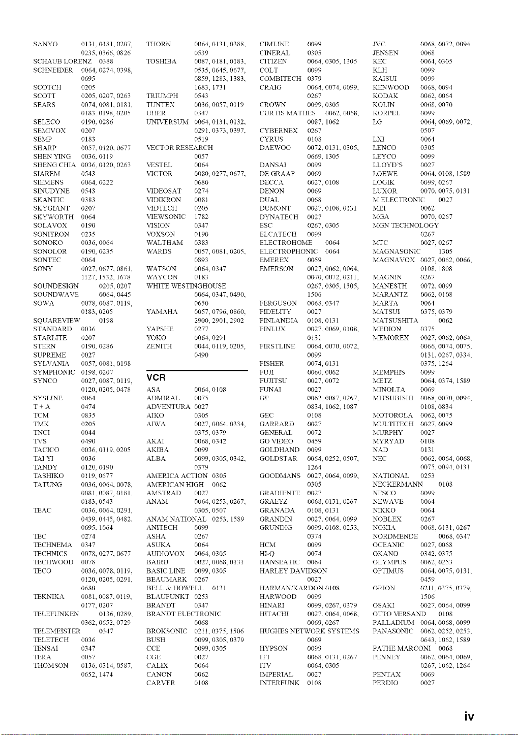
SANYO 0131, 0t81. 0207, THORN 0064, 0131. 0388. C IMLINE 0099 JVC 0068, 0072. 0094
0235. 0366, 0826 0539 ( INERAL 0305 JENSEN 0068
SCHAUB LORENZ 0388 TOSHIBA 0087, 0181. 0183. CITIZEN 0064. 0305, I305 KEC 0064, 0305
SCHNEIDER 0064, 0274. 0398, 0535, 0645. 0677, COLT 0099 KLH 0099
0695 0859, I283. 1383, (OMBITECH 0379 KAISUI 0099
SCOTCH 0205 1683, I731 CRAIG 0064. 0074, 0099. KENWOOD 0068. 0094
SCOTT 0205, 0207. 0263 TRIUMPH 0543 0267 KODAK 0062. 0064
SEARS 0074,0081.018t, TUNTEX 0036,0057.0119 ( RO\:_,_'N 0099.0305 KOLIN 0068.0070
0t 83. 0198, 0205 UHER 0347 CURTIS MATHES 0062. 0068. KORPEL 0099
SELECO 0190,0286 UNIVERSUM 0064,0131.0t32. 0087, 1062 LG 0064,0069.0072,
SEMIVOX 0207 0291, 0373. 0397, CYBERNEX 0267 0507
SEMP 0183 0519 CYRUS 0108 LXI 0064
SHARP 0057, 0120. 0677 VECTOR RESEARCH DAEWOO 0072, 0131, 0305. LENCO 0305
SHEN YING 0036, 0tt9 0057 0669, 1305 LEYCO 0099
SHENG CHIA 0036,0120.0263 XNSTEL 0064 DANSAI 0099 LLOYD'S 0027
\2( TOR 0080, 0277. 0677. DE GRAAF 0069 LOEWE 0064, 0t08. 1589
SIAREM 0543
SIEMENS 0064, 0222 0680
SINUDYNE 0543 VIDEOSAT 0274
SKANTIC 0383 VIDIKRON 0081
SKYGIANT 0207 \_DTE( H 0205
SKYWORTH 0064 VIEWSONI( 1782
SOLAVOX 0190 VISION 0347
SONITRON 0235 VOXSON 0190
SONOKO 0036, 0064 WALTHAM 0383
SONOLOR 0190, 0235
SONTEC 0064
DECCA 0027.0108 LOGIK 0099. 0267
DENON 0069 LUXOR 0070. 0075.0 t3 t
DUAL 0068 M ELECTRONIC 0027
DUMONT 0027, 0108, 0131 MEI 0062
Dk_qATECH 0027 MGA 0070, 0267
ESC 0267.0305 MGN TECHNOLOGY
ELCATE( H 0099 0267
ELECTROHOME 0064 MT( 0027, 0267
SOUNDWAVE 0064, 0445
SOWA 0078, 0087, 0119,
0183. 0205
SQUAREVIEW 0198
STANDARD 0036
STARLITE 0207
STERN 0190, 0286
SUPREME 0027
SYLVANIA 0057, 008t. 0198
SYMPHONIC? 0198. 0207
S_'NCO 0027.0087 0119. VCR
0120. 0205, 0478 ASA
SYSLINE 0064
T + A 0474
TOM 0835
WARDS 0057, 0081, 0205, ELECTROPHONIC 0064 MAGNASONIC 1305
0893 EMEREX 0059 MAGNAVOX 0027, 0062. 0066,
SONY 0027, 0677, 086t, WATSON 0064, 0347 EMERSON 0027, 0062, 0064. 0t08. 1808
1127. 1532, 1678 WAYCON 0183 0070, 0072, 0211. MAGNIN 0267
SOUNDESIGN 0205, 0207 WHITE WESTINGHOUSE 0267, 0305, 1305. MANESTH 0072. 0099
0064, 0347. 0490, 1506 MARANTZ 0062, 0108
0650 FERGUSON 0068.0347 MARTA 0064
YAMAHA 0057, 0796, 0860. FIDELITY 0027 MATSUI 0375, 0379
2900, 2901. 2902 FINLANDIA 0108.0131 MATSUSHITA 0062
YAPSHE 0277 FINLUX 0027, 0069, 0108. MEDION 0375
YOKO 0064, 0291 013t MEMOREX 0027, 0062, 0064,
ZENITH 0044, 0119, 0205. FIRSTLINE 0064, 0070, 0072. 0066. 0074, 0075,
0490 0099 0131. 0267, 0334,
FISHER 0074, 0131 0375, 1264
FUJI 0060. 0062 MEMPHIS 0099
FUJITSU 0027.0072 METZ 0064, 0374. 1589
0064, 0108 FL'NAI 0027 MINOLTA 0069
ADMIRAL 0075 GE 0062. 0087, 0267. MITSUBISHI 0068, 0070, 0094,
ADVENTUtK_K 0027 0834, 1062, 1087 0t08, 0834
AIKO 0305 GE( 0108 MOTOROLA 0062. 0075
TiVlK 0205 AI\VA 0027, 0064, 0334. GARP_4.RD 0027 MULTITECH 0027. 0099
TNCI 0044 0375, 0379 GENERAL 0072 MURPHY 0027
TVS 0490 AKAI 0068, 0342 GO VIDEO 0459 MYRYAD 0108
TA( I( O 0036,01t9,0205 AKIBA 0099 GOLDHAND 0099 NAD 0131
TAI YI 0036 ALBA 0099, 0305, 0342, GOLDSTAR 0064, 0252, 0507. NEC 0062. 0064, 0068,
TANDY 0120, 0190 0379 1264 0075.0094, 013 t
TASHIKO 0119. 0677 AMERICA ACTION 0305 GOODMANS 0027, 0064, 0099. NATIONAL 0253
TATL_rNG 0036, 0064, 0078, AMERICAN HIGH 0062 0305 NECKERMANN 0108
0081. 0087, 0181. AMSTRAD 0027 GRADIENTE 0027 NES(O 0099
0t83. 0543 ANAM 0064, 0253, 0267, GRAETZ 0068, 0131, 0267 NEWAVE 0064
TEA( 0036, 0064, 0291, 0305, 0507 GRANADA 0108. 0131 NIKKO 0064
0439.0445,0482. ANAMNATIONAL 0253, 1589 GRANDIN 0027,0064,0099 NOBLEX 0267
0695. 1064 ANITECH 0099 GRUNDIG 0099. 0108, 0253. NOKIA 0068. 0t3t. 0267
TEC 0274 ASHA 0267 0374 NORDMENDE 0068, 0347
TECHNEMA 0347 ASUKA 0064 HCM 0099 OCEANIC 0027, 0068
TECHNICS 0078, 0277. 0677 AUDIOVOX 0064, 0305 HI-Q 0074 OKANO 0342. 0375
TECHWOOD 0078 BAIRD 0027, 0068, 0131 HANSEATIC 0064 OLYMPUS 0062, 0253
TECO 0036, 0078. 0119. BASIC LINE 0099, 0305 HARLEY DAVIDSON OPTIMUS 0064, 0075.013 I,
0120, 0205, 0291. BEAUiVlARK 0267 0027 0459
0680 BELL & HO'%VELL 0131 HARiVlANiKARDON 0108 ORION 0211, 0375, 0379,
TEKNIKA 0081.0087.0119. BLAUPL _rNKT 0253 HAR\VOOD 0099 1506
0177. 0207 BtK4.NDT 0347 HINARI 0099, 0267, 0379 OSAKI 0027. 0064. 0099
TELEFUNKEN 0136, 0289. BtK4NDT ELECTRONIC HITACHI 0027. 0064, 0068. OTTO VERSAND 0108
0362. 0652, 0729 0068 0069, 0267 PALLADIUM 0064. 0068. 0099
TELEMEISTER 0347 BROKSONIC 0211. 0375, I506 HUGHES NETWORK SYSTEMS PANASONI( 0062. 0252, 0253,
TELETECH 0036 BUSH 0099, 0305, 0379 0069 0643. 1062, 1589
TENSAI 0347 CCE 0099, 0305 HYPSON 0099 PATHE MARCONI 0068
TERA 0057 CGE 0027 ITT 0068, 0131, 0267 PENNEY 0062, 0064, 0069,
THOMSON 0136, 0314, 0587, CALIX 0064 ITV 0064. 0305 0267. 1062, 1264
0652. 1474 CANON 0062 IMPERIAL 0027 PENTAX 0069
CARVER 0108 INTERFLrNK 0t08 PERDIO 0027
iv
PHILC O 0062
PHILIPS 0062, 0t08, 0645,
i108. i208
PHONOLA 0t08
PILOT 0064
PIONEER 0069, 0094, 0108
POLK AUDIO 0108
PROFITRONIC 0267
PROLINE 0027
PROSC AN 008Z 1087
PROTEC 0099
PE LSAR 0066
PYE 0108
QUASAR 0062 1062
QUELLE 0108
RCA 0062 0069, 0087,
0267, 0834.1062,
1087
RADIOSHACK 0027
tLa.DIOLA 0108
tLa.DIX 0064
tL4NDEX 0064
REALISTIC 0027. 0062. 0064,
0074. 0075, 0131
REOC 0375
REPLAYTV 0641. 0643
REX 0068
ROADSTAR 0064. 0099. 0267.
0305
RE.CO 0066
SBR 0108
SEG 0267
SEI 0t08
STS 0069
SABA 0068, 0347
SALORA 0070
SAMPO 0064. 0075
SAMSE_G 0072. 0267. 0459
SANKY 0066. 0075
SANSUI 0027. 0068. 0094,
1506
SANYO 0074, 0131,0267
SAVILLE 0379
SCHAUB LORENZ 0027,0068.
0131
SCHNEIDER 0027, 0099. 0108
SCOTT 0070, 0072, 0211
SEARS 0027. 006Z 0064,
0069. 0074.0131.
1264
SELECO 0068
SEMP 0072
SHARP 0075. 0834
SHINTOM 0099.013t
SIEMENS 0064.0108.0131
SILVA 0064
SINGER 007Z 0099
SINUDYNE 0108
SONIC BLUE 0641. 0643
SONTEC 0064
SONY 0027, 0059, 0060,
0062. 0663, 1259
SE*_'_KAI 0375
SE_STAR 0027
SE*_'_TRONIC 0027
SYLVANIA 0027 0062 0108.
0070. 1808
SYMPHONIC 0027
TMK 0267
TANDY 0027. 013t
TASHIKO 0027. 0064
TATE_G 0027. 0068, 0072.
0094. 0108
TEAC 0027, 0068, 0305,
0334. 0669
TECHNICS 0062. 0253
TECO 006Z 0064. 0068,
0075
TEKNIKA 0027, 0062 0064
TELEAVIA 0068
TELEFUNKEN 0068. 0347
TENOSAL 0099
TENSAI 0027
THOMAS 0027
THOMSON 0068, 0087, 0094,
0347
THORN 0068.0131
TIVO 0645. 0663
TOSHIBA 0068, 0070, 0072,
0094. 0108, 0872
TOTEVISION 0064. 0267
UHER 0267
E,:'NITECH 0267
L_IVERSETM 0027.0064,0108,
0267
VECTOR 0072
\'ICTOR 0068. 0094
\'IDEO CONCEPTS 0072
\'IDEOMAGIC 0064
\'IDEOSONIC 0267
VILLAIN 0027
X_2_RDS 0027. 0062, 0069,
0074. 0075, 0087,
0099. 0108, 0267
WHITE WESTINGHOUSE
0099
XR-1000 0027. 0062, 0099
"_%MAHA 0068
"_%MISHI 0099
"_KAN 0099
YOKO 0267
ZENITH 0027. 0060, 0066.
i506
© 2005 YAMAHA CORPORATION All rights reserved.
YAMAHA ELECTRONICS CORPORATION, USA 6660 OBANGETHORPE AVE., BUENA PARK, CALIF. 90620, U.S.A.
YAMAHA CANADA MUSIC LTD. 135 MILNER AVE., SCABBOBOUGH, ONTARIO M1S 3R1, CANADA
YAMAHA ELECTRONIK EUROPA G.m.b,H. SIEMENSSTR. 2234, 25462 BELUNGEN BEI HAMBURG, GERMANY
YAMAHA ELECTRONIQUE FRANCE S.A. RUE AMBROISE CROIZAT SP70 CROISSY-BEAUBOURG 77312 MARNE-LA-VALLEE CEDEX02, FRANCE
YAMAHA ELECTRONICS (UK) LTD. YAMAHA HOUSE, 200 BICKMANSWOBTH ROAD WATFOBD, HERTS WD18 7GQ, ENGLAND
YAMAHA SCANDINAVIA A.B. J A WETTERGRENS GATA 1, BOX 30053, 400 43 V,_,STRA FROLUNDA, SWEDEN
YAMAHA M USIC AUSTRALIA PTY, LTD. 17-33 MARKET ST., SOUTH MELBOURNE, 3205 VIC., AUSTRALIA
YAMAHA CORPORATION
Printed in Malaysia c WE64820