PN# 36420Supplement, 10/27/2008
NOTE: For Wall Button, wire and insulated
staples locate Bags 6 and 7 from Box 2.
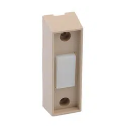
1. Wall Button location.
• Wall Button location should be in direct sight
of door.
• It should be at least five feet (5') above floor to
prevent small children from operating door.
• It must be away from any moving parts. (You
should NOT be able to reach the garage door
while standing at Wall Button.)
• Wall Button board screw connections are
polarized, (+) positive and (-) negative.
2a. Wiring (If pre-wired).
• Locate Wall Button pre-wired wire ends
(Fig. 3-1). (They should be located within the
guidelines mentioned above.)
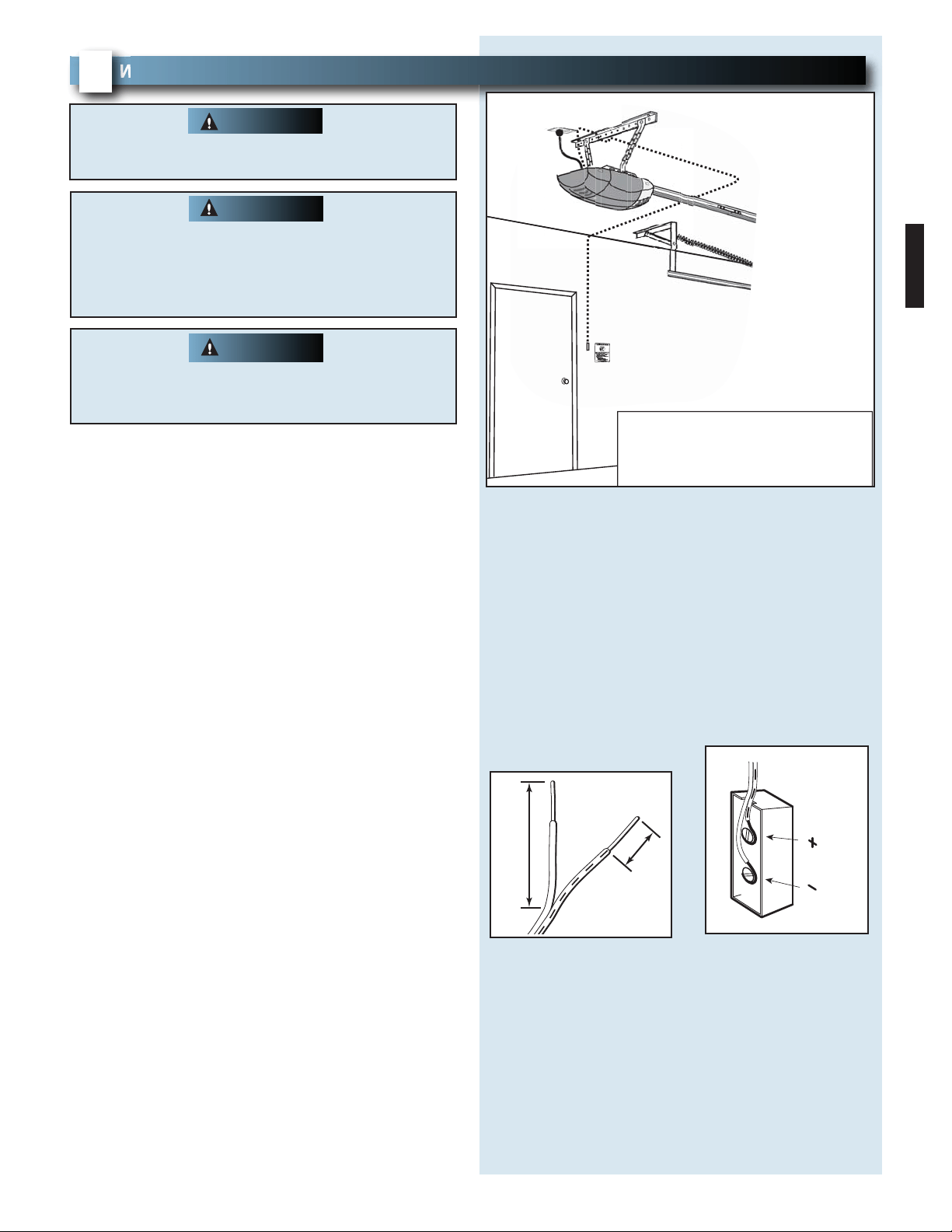
• Split and strip ends of wire (Fig. 3-2).
• Fasten wire to Wall Button board screws on back
of Wall Button.
– Striped wire to the + (plus) terminal.
– White wire to the - (minus) terminal.
2b. Wiring (If NOT pre-wired).
• Pick a convenient location for mounting
Wall Button using the guidelines mentioned
above (Fig. 3-1).
• Run wire from Wall Button to power head
(Fig. 3-1).
• Split and strip ends of wire (Fig. 3-2).
• Fasten wire to control board screws on back of
Wall Button.
– Striped wire to the + (plus) terminal.
– White wire to the - (minus) terminal.
WALL BUTTON INSTALLATION
FOR HELP-1.800.354.3643 OR WWW.GENIECOMPANY.COM
3
Verify there is NO power to the opener before
installing Wall Button wires and Wall Button.
WARNING
Staples which are too tight can cut or pinch wires.
Cut or pinched wires can cause the Wall button to
stop working. When using the insulated staples,
make sure you fasten them only as tightly as
needed to hold the wire snugly.
CAUTION
FIG. 3-2 Splitting and stripping
.
FIG.3-1 Wall Button wire routing
Wire from
power head
to wall control.
Wall
control
"Entrapment"
warning label
Separate
entry door
EXAMPLE ONLY!
This is an example of wire routing
when NOT pre-wired. Your wire
routing may be different.
1/2"
2"
15
or
or
B
W
Use of any other wall control can cause the door to
operate unexpectedly and the light not to work.
Use only the included Wall Button.
WARNING
PN# 36420Supplement, 10/27/2008
16
3.Securely fasten wires.
• Securely fasten wires to ceiling and
wall using insulated staples provided.
– Use insulated staples.
– Staples should be snug only.
• If rear cover is attached to power head,
remove it.
• On power head:
– Route Wall Button wires through wire guide.
– Split and strip ends of wire (Fig. 3-2 on
previous page).
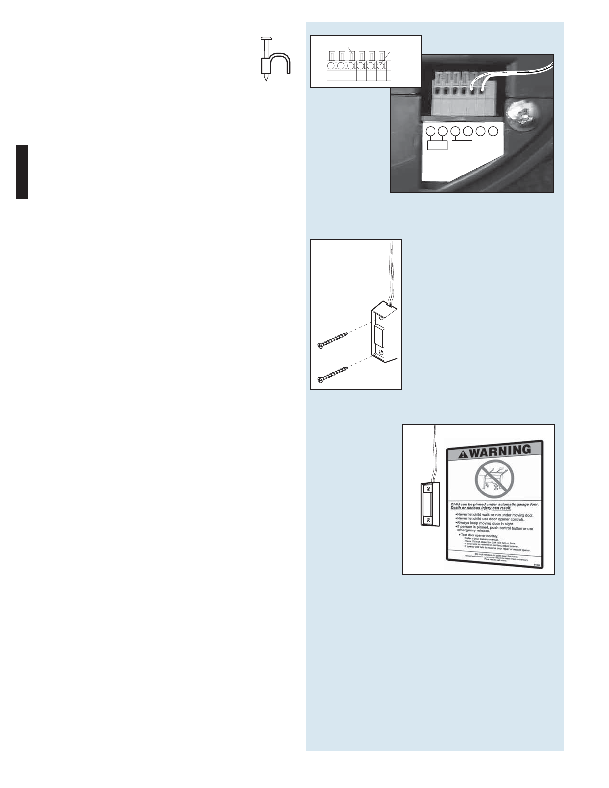
– Insert wire into terminal holes and lightly press in
the orange locking clips above each terminal
hole. (You can use a pencil or small screwdriver
to comfortably press in locking clips.) The white
wire into #1 terminal hole and striped wire into
the #2 terminal hole.
– Confirm wire lock by lightly tugging on the wire.
The wire should remain in the terminal hole.
• Do NOT install rear cover yet.
4. Mounting.
• Fasten Wall Button to wall with 2 screws
(provided) (Fig. 3-4).
• Remove protective backing from "Entrapment"
warning label (Fig. 3-5). The "Entrapment" label
is located in the center of this manual.
– Stick label on wall near Wall Button.
FIG. 3-4 Mounting Wall Button.
Insulated
Staple
+–
PB
Infared Sensor
123456
FIG. 3-3 Insert wires
.
(Power Head With Rear Cover Removed)
1234
Terminal
Holes
Locking
Clips
56
FIG. 3-5 Mounting Entrapment warning label.