OperatiOn Manual
MOde d’eMplOi
Bedienungsanleitung
MOdO de eMpleO
12 SERIES
EQUALIZER
IMPORTANT SAFETY INFORMATION
The symbols shown above are internationally accepted symbols that warn of
potential hazards with electrical products. The lightning flash with arrowpoint in
an equilateral triangle means that there are dangerous voltages present within
the unit. The exclamation point in an equilateral triangle indicates that it is nec-
essary for the user to refer to the owner’s manual.
These symbols warn that there are no user serviceable parts inside the unit. Do
not open the unit. Do not attempt to service the unit yourself. Refer all servic-
ing to qualified personnel. Opening the chassis for any reason will void the
manufacturer’s warranty. Do not get the unit wet. If liquid is spilled on the unit,
shut it off immediately and take it to a dealer for service. Disconnect the unit
during storms to prevent damage.
CAUTION
ATTENTION:
RISQUE DE CHOC ELECTRIQUE - NE PAS OUVRIR
WARNING:
TO REDUCE THE RISK OF FIRE OR ELECTRIC
SHOCK DO NOT EXPOSE THIS EQUIPMENT TO RAIN OR MOISTURE
RISK OF ELECTRIC SHOCK
DO NOT OPEN
WARNING FOR YOUR PROTECTION
READ THE FOLLOWING:
KEEP THESE INSTRUCTIONS
HEED ALL WARNINGS
FOLLOW ALL INSTRUCTIONS
THE APPARATUS SHALL NOT BE EXPOSED TO DRIPPING OR SPLASHING
LIQUID AND NO OBJECT FILLED WITH LIQUID, SUCH AS VASES, SHALL BE
PLACED ON THE APPARATUS.
CLEAN ONLY WITH A DRY CLOTH.
DO NOT BLOCK ANY OF THE VENTILATION OPENINGS. INSTALL IN AC-
CORDANCE WITH THE MANUFACTURER’S INSTRUCTIONS.
DO NOT INSTALL NEAR ANY HEAT SOURCES SUCH AS RADIATORS,
HEAT REGISTERS, STOVES, OR OTHER APPARATUS (INCLUDING AMPLI-
FIERS) THAT PRODUCE HEAT.
ONLY USE ATTACHMENTS/ACCESSORIES SPECIFIED BY THE MANUFAC-
TURER.
UNPLUG THIS APPARATUS DURING LIGHTNING STORMS OR WHEN
UNUSED FOR LONG PERIODS OF TIME.
Do not defeat the safety purpose of the polarized or grounding-type plug. A
polarized plug has two blades with one wider than the other. A grounding
type plug has two blades and a third grounding prong. The wide blade or third
prong are provided for your safety. If the provided plug does not fit your outlet,
consult an electrician for replacement of the obsolete outlet.
Protect the power cord from being walked on or pinched particularly at plugs,
convenience receptacles, and the point where they exit from the apparatus.
Use only with the cart stand, tripod bracket, or table specified by the manufac-
ture, or sold with the apparatus. When a cart is used, use caution when moving
the cart/apparatus combination to avoid injury from tip-over.
Refer all servicing to qualified service personnel. Servicing is required when
the apparatus has been damaged in any way, such as power-supply cord or plug
is damaged, liquid has been spilled or objects have fallen into the apparatus, the
apparatus has been exposed to rain or moisture, does not operate normally, or
has been dropped.
POWER ON/OFF SWITCH: If the equipment has a Power switch, the Power
switch used in this piece of equipment DOES NOT break the connection from
the mains.
MAINS DISCONNECT: The plug shall remain readily operable. For rack-mount
or installation where plug is not accessible, an all-pole mains switch with a
contact separation of at least 3 mm in each pole shall be incorporated into the
electrical installation of the rack or building.
FOR UNITS EQUIPPED WITH EXTERNALLY ACCESSIBLE FUSE RECEPTA-
CLE: Replace fuse with same type and rating only.
MULTIPLE-INPUT VOLTAGE: This equipment may require the use of a different
line cord, attachment plug, or both, depending on the available power source at
installation. Connect this equipment only to the power source indicated on the
equipment rear panel. To reduce the risk of fire or electric shock, refer servicing
to qualified service personnel or equivalent.
If connected to 240V supply, a suitable CSA/UL certified power cord shall be
used for this supply.
Safety InStructIonS
NOTICE FOR CUSTOMERS IF YOUR UNIT IS EQUIPPED WITH A POWER CORD.
WARNING: THIS APPLIANCE SHALL BE CONNECTED TO A MAINS SOCKET OUTLET WITH A
PROTECTIVE EARTHING CONNECTION.
The cores in the mains lead are coloured in accordance with the following code:
GREEN and YELLOW - Earth BLUE - Neutral BROWN - Live
As colours of the cores in the mains lead of this appliance may not correspond with the coloured
markings identifying the terminals in your plug, proceed as follows:
•
The core which is coloured green and yellow must be connected to the terminal in the plug
marked with the letter E, or with the earth symbol, or coloured green, or green and yellow.
•
The core which is coloured blue must be connected to the terminal marked N or coloured
black.
•
The core which is coloured brown must be connected to the terminal marked L or coloured
red.
This equipment may require the use of a different line cord, attachment plug, or both, depending
on the available power source at installation. If the attachment plug needs to be changed, refer
servicing to qualified service personnel who should refer to the table below. The green/yellow
wire shall be connected directly to the units chassis.
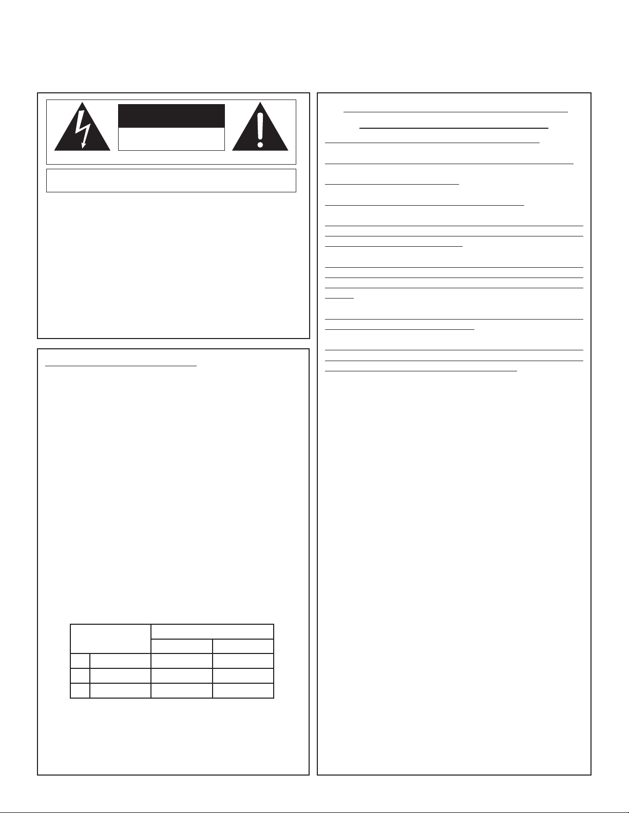
CONDUCTOR
WIRE COLOR
Normal Alt
L LIVE BROWN BLACK
N NEUTRAL BLUE WHITE
E EARTH GND
GREEN/
YEL
GREEN
WARNING: If the ground is defeated, certain fault conditions in the unit or in the system to
which it is connected can result in full line voltage between chassis and earth ground. Severe
injury or death can then result if the chassis and earth ground are touched simultaneously.
WARNING FOR YOUR PROTECTION
READ THE FOLLOWING:
KEEP THESE INSTRUCTIONS
HEED ALL WARNINGS
FOLLOW ALL INSTRUCTIONS
THE APPARATUS SHALL NOT BE EXPOSED TO DRIPPING OR SPLASHING
LIQUID AND NO OBJECT FILLED WITH LIQUID, SUCH AS VASES, SHALL BE
PLACED ON THE APPARATUS.
CLEAN ONLY WITH A DRY CLOTH.
DO NOT BLOCK ANY OF THE VENTILATION OPENINGS. INSTALL IN AC-
CORDANCE WITH THE MANUFACTURER’S INSTRUCTIONS.
DO NOT INSTALL NEAR ANY HEAT SOURCES SUCH AS RADIATORS,
HEAT REGISTERS, STOVES, OR OTHER APPARATUS (INCLUDING AMPLI-
FIERS) THAT PRODUCE HEAT.
ONLY USE ATTACHMENTS/ACCESSORIES SPECIFIED BY THE MANUFAC-
TURER.
UNPLUG THIS APPARATUS DURING LIGHTNING STORMS OR WHEN
UNUSED FOR LONG PERIODS OF TIME.
Do not defeat the safety purpose of the polarized or grounding-type plug. A
polarized plug has two blades with one wider than the other. A grounding
type plug has two blades and a third grounding prong. The wide blade or third
prong are provided for your safety. If the provided plug does not fit your outlet,
consult an electrician for replacement of the obsolete outlet.
Protect the power cord from being walked on or pinched particularly at plugs,
convenience receptacles, and the point where they exit from the apparatus.
Use only with the cart stand, tripod bracket, or table specified by the manufac-
ture, or sold with the apparatus. When a cart is used, use caution when moving
the cart/apparatus combination to avoid injury from tip-over.
Refer all servicing to qualified service personnel. Servicing is required when
the apparatus has been damaged in any way, such as power-supply cord or plug
is damaged, liquid has been spilled or objects have fallen into the apparatus, the
apparatus has been exposed to rain or moisture, does not operate normally, or
has been dropped.
POWER ON/OFF SWITCH: If the equipment has a Power switch, the Power
switch used in this piece of equipment DOES NOT break the connection from
the mains.
MAINS DISCONNECT: The plug shall remain readily operable. For rack-mount
or installation where plug is not accessible, an all-pole mains switch with a
contact separation of at least 3 mm in each pole shall be incorporated into the
electrical installation of the rack or building.
FOR UNITS EQUIPPED WITH EXTERNALLY ACCESSIBLE FUSE RECEPTA-
CLE: Replace fuse with same type and rating only.
MULTIPLE-INPUT VOLTAGE: This equipment may require the use of a different
line cord, attachment plug, or both, depending on the available power source at
installation. Connect this equipment only to the power source indicated on the
equipment rear panel. To reduce the risk of fire or electric shock, refer servicing
to qualified service personnel or equivalent.
If connected to 240V supply, a suitable CSA/UL certified power cord shall be
used for this supply.
This Equipment Is Intended For Rack Mount Use Only.
Safety InStructIonS
NOTICE FOR CUSTOMERS IF YOUR UNIT IS EQUIPPED WITH A POWER CORD.
WARNING: THIS APPLIANCE SHALL BE CONNECTED TO A MAINS SOCKET OUTLET WITH A
PROTECTIVE EARTHING CONNECTION.
The cores in the mains lead are coloured in accordance with the following code:
GREEN and YELLOW - Earth BLUE - Neutral BROWN - Live
As colours of the cores in the mains lead of this appliance may not correspond with the coloured
markings identifying the terminals in your plug, proceed as follows:
•
The core which is coloured green and yellow must be connected to the terminal in the plug
marked with the letter E, or with the earth symbol, or coloured green, or green and yellow.
•
The core which is coloured blue must be connected to the terminal marked N or coloured
black.
•
The core which is coloured brown must be connected to the terminal marked L or coloured
red.
This equipment may require the use of a different line cord, attachment plug, or both, depending
on the available power source at installation. If the attachment plug needs to be changed, refer
servicing to qualified service personnel who should refer to the table below. The green/yellow
wire shall be connected directly to the units chassis.
CONDUCTOR
WIRE COLOR
Normal Alt
L LIVE BROWN BLACK
N NEUTRAL BLUE WHITE
E EARTH GND
GREEN/
YEL
GREEN
WARNING: If the ground is defeated, certain fault conditions in the unit or in the system to
which it is connected can result in full line voltage between chassis and earth ground. Severe
injury or death can then result if the chassis and earth ground are touched simultaneously.
LITHIUM BATTERY
WARNING
CAUTION!
This product may contain a lithium battery. There is danger of
explosion if the battery is incorrectly replaced. Replace only with
an Eveready CR 2032 or equivalent. Make sure the battery is
installed with the correct polarity. Discard used batteries according
to manufacturer’s instructions.
ADVARSEL!
Lithiumbatteri - Eksplosjonsfare. Ved utskifting benyttes kun batteri
som anbefalt av apparatfabrikanten. Brukt batteri returneres appa-
ratleverandøren.
ADVARSEL!
Lithiumbatteri - Eksplosionsfare ved fejlagtig håndtering.
Udskiftning må kun ske med batteri av samme fabrikat og type.
Levér det brugte batteri tilbage til leverandøren.
VAROITUS!
Paristo voi räjähtää, jos se on virheellisesti asennettu. Vaihda paristo
ainoastaan laitevalmistajan suosittelemaan tyyppin. Hävitä käytetty
paristo valmistajan ohjeiden mukaisesti.
VARNING!
Explosionsfara vid felaktigt batteribyte. Använd samma batterityp
eller en ekvivalent typ som rekommenderas av apparattillverkaren.
Kassera använt batteri enligt fabrikantens instruktion.
IMPORTANT SAFETY INFORMATION
U.K. MAINS PLUG WARNING
A molded mains plug that has been cut off from the cord is unsafe.
Discard the mains plug at a suitable disposal facility. NEVER
UNDER ANY CIRCUMSTANCES SHOULD YOU INSERT A
DAMAGED OR CUT MAINS PLUG INTO A 13 AMP
POWER SOCKET. Do not use the mains plug without the fuse
cover in place. Replacement fuse covers can be obtained from your
local retailer. Replacement fuses are 13 amps and MUST be ASTA
approved
to BS1362.
ELECTROMAGNETIC COMPATIBILITY
This unit conforms to the Product Specifications noted
on the Declaration of Conformity. Operation is sub-
ject to the following two conditions:
•thisdevicemaynotcauseharmfulinterference,and
•this device mustacceptany interference received,
including interference that may cause undesired
operation.
Operation of this unit within significant electromagnetic
fields should be avoided.
•useonlyshieldedinterconnectingcables.
Warranty
This warranty is valid only for the original purchaser and only in the United States.
1. The warranty registration card that accompanies this product must be mailed within 30
days after purchase date to validate this warranty. You can also register online at
www.dbxpro.com. Proof-of-purchase is considered to be the responsibility of the consumer.
A copy of the original purchase receipt must be provided for any warranty service.
2. dbx warrants this product, when bought and used solely within the U.S., to be free from
defects in materials and workmanship under normal use and service.
3. dbx liability under this warranty is limited to repairing or, at our discretion, replacing
defective materials that show evidence of defect, provided the product is returned to dbx
WITH RETURN AUTHORIZATION from the factory, where all parts and labor will be covered up
to a period of two years. A Return Authorization number must first be obtained from dbx. The
company shall not be liable for any consequential damage as a result of the product’s use in
any circuit or assembly.
4. dbx reserves the right to make changes in design or make additions to or improvements
upon this product without incurring any obligation to install the same additions or improve-
ments on products previously manufactured.
5. The foregoing is in lieu of all other warranties, expressed or implied, and dbx neither
assumes nor authorizes any person to assume on its behalf any obligation or liability in con-
nection with the sale of this product. In no event shall dbx or its dealers be liable for special
or consequential damages or from any delay in the performance of this warranty due to
causes beyond their control.
Manufacturer’s Name: dbx Professional Products
Manufacturer’s Address: 8760 S. Sandy Parkway
Sandy, Utah 84070, USA
declares that the product:
Product name: dbx 1215 and dbx1231
Note: Product name may be suffixed by the letters-EU.
Product option: None
conforms to the following Product Specifications:
Safety: IEC 60065 -01+Amd 1
EMC: EN 55022:2006 (N/A; Analog Product)
IEC61000-4-2
IEC61000-4-3
IEC61000-4-4
IEC61000-4-5
IEC61000-4-6
IEC61000-4-8
IEC61000-4-11
Supplementary Information:
The product herewith complies with the requirements of the:
Low Voltage Directive 2006/95/EC
EMC Directive 2004/108/EC.
RoHS Directive 2002/95/EC
WEEE Directive 2002/96/EC
With regard to Directive 2005/32/EC and EC Regulation
1275/2008 of 17 December 2008, this product is designed,
produced, and classified as Professional Audio Equipment and
thus is exempt from this Directive.
Roger Johnsen
Director, Engineering
Signal Processing
8760 S. Sandy Parkway
Sandy, Utah 84070, USA
Date: November 19, 2010
European Contact: Your local dbx Sales and Service Office or
Harman Music Group
8760 South Sandy Parkway
Sandy, Utah 84070 USA
Ph: (801) 566-8800
Fax: (801) 568-7583
DECLARATION OF CONFORMITY
If you want to dispose this product, do not mix it with general household waste. There is a
separate collection system for used electronic products in accordance with legislation that
requires proper treatment, recovery and recycling.
Private household in the 25 member states of the EU, in Switzerland and Norway may return their
used
electronic products free of charge to designated collection facilities or to a retailer (if you purchase a
similar
new one).
For Countries not mentioned above, please contact your local authorities for a correct method of disposal.
By doing so you will ensure that your disposed product undergoes the necessary treatment, recovery
and
recycling and thus prevent potential negative effects on the environment and human health.


1
Manual Contents
IntroductIon. . . . . . . . . . . . . . . . . . . . . . . . . . . . . . . . . . . . . . . . . . . . . . . . . . 2
InspectIon . . . . . . . . . . . . . . . . . . . . . . . . . . . . . . . . . . . . . . . . . . . . . . . . . . . . 2
operatIng controls . . . . . . . . . . . . . . . . . . . . . . . . . . . . . . . . . . . . . . . . . . . 2
connectIng the eQ to your system . . . . . . . . . . . . . . . . . . . . . . . . . . . . . . 3
rear panel descrIptIons. . . . . . . . . . . . . . . . . . . . . . . . . . . . . . . . . . . . . . . . 4
InstallatIon consIderatIons . . . . . . . . . . . . . . . . . . . . . . . . . . . . . . . . . . . . 5
operatIon and applIcatIons notes. . . . . . . . . . . . . . . . . . . . . . . . . . . . . . . 5
technIcal support / Factory servIce . . . . . . . . . . . . . . . . . . . . . . . . . . . . . 6
FrançaIs . . . . . . . . . . . . . . . . . . . . . . . . . . . . . . . . . . . . . . . . . . . . . . . . . . . . . 7
deutsch . . . . . . . . . . . . . . . . . . . . . . . . . . . . . . . . . . . . . . . . . . . . . . . . . . . . . 17
español . . . . . . . . . . . . . . . . . . . . . . . . . . . . . . . . . . . . . . . . . . . . . . . . . . . . . 27
specIFIcatIons . . . . . . . . . . . . . . . . . . . . . . . . . . . . . . . . . . . . . . . . . . . . . . . . . 37
Block dIagram. . . . . . . . . . . . . . . . . . . . . . . . . . . . . . . . . . . . . . . . . . . . . . . . 39
MANUAL CONTENTS
12 SERIES GRAPHIC EQUALIZERS
IntroduCtIon
Congratulations on your purchase of a dbx graphic equalizer. All dbx graphic equalizers are high performance
multi-functional units designed to deliver all the flexibility and power that professional users demand. We recom-
mend that you take a moment to read through this operation manual. It provides information that will assist you
from system set-up to EQ applications. The 12 Series Equalizers include the following features:
•SwitchableBoost/Cutrangebetween±6dBand±15dB
•Balancedinputsandoutputs
•XLR,BarrierStrip,and1/4"TRSconnectors
•-12dB/+12dBinputgainrange
•18dB/octave40HzBesselLow-Cutfilter
•Chassis/signalgroundliftcapability
•Internalpowersupplytransformer
•Power-offhard-wirerelaybypasswith2-secondpower-updelay
InspeCtIon
Verify that the equalizer’s package contains the following:
•Equalizerunitmatchingserialnumbermarkedonpackage
•ACpowercord
•OperationManual
•RegistrationCard
•Fourrackmountscrewsandwashers
If any of these items are missing please contact dbx customer service at the number provided on the back cover of
this manual.
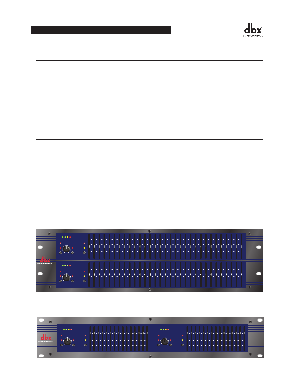
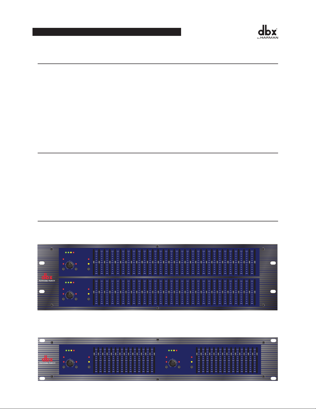
operatIng Controls
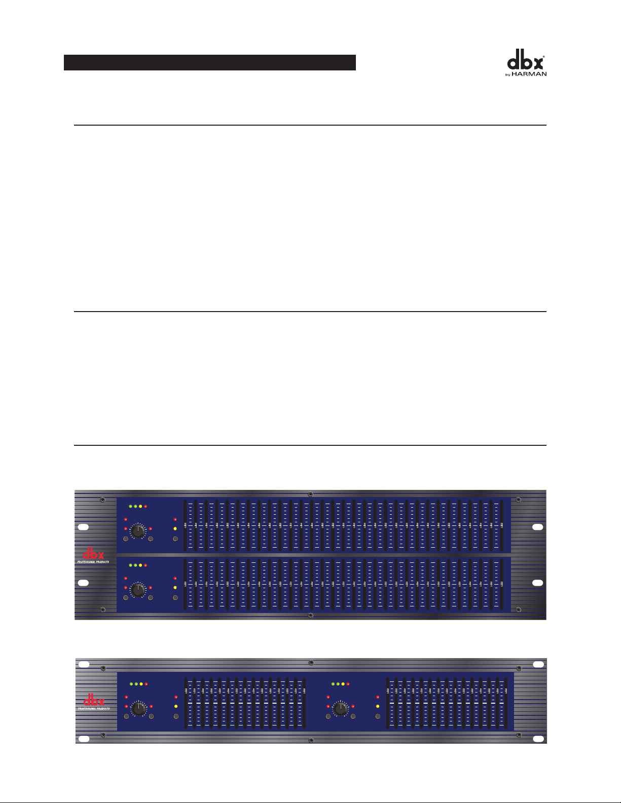
Front Panels
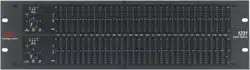
1231 - dual channel 31 band graphic equalizer
1215-dualchannel15bandgraphicequalizer
2
OPERATION MANUAL
1231
Graphic Equalizer
20 25 31.5 40 50 63 80 500400315250 1.6k1.25k1k800 5k4k3.15k2.5k 16k12.5k10k8k6.3k 20k2k630100 125 160 200
RANGE
OUTPUT
LEVEL (dBu)
LOW
CUT
EQ
BYPASS
INPUT
GAIN
dB
-12
0
+12
+/-6
+/-15
CLIP
+18+100-10
RANGE
OUTPUT
LEVEL (dBu)
LOW
CUT
EQ
BYPASS
INPUT
GAIN
dB
-12
0
+12
+/-6
+/-15
CLIP
+18+100-10
0
-15
+15
0
-15
+15
0
-6
+6
0
-6
+6
85-XXXX-X 1231 FRONT ART 7-12-99
RANGE
OUTPUT
LEVEL (dBu)
LOW
CUT
EQ
BYPASS
INPUT
GAIN
dB
-12
0
+12
+/-6
+/-15
CLIP
0
-6
+6
25 40 63 100 160 250 400 16k10k6.3k4k630 1k 1.6k 2.5k
+18+100-10
1215
Graphic Equalizer
85-XXXX-A0 1215 FRONT ART 7-15-99
0
-15
+15
RANGE
OUTPUT
LEVEL (dBu)
LOW
CUT
EQ
BYPASS
INPUT
GAIN
dB
-12
0
+12
+/-6
+/-15
CLIP
0
-6
+6
25 40 63 100 160 250 400 16k10k6.3k4k630 1k 1.6k 2.5k
+18+100-10
0
-15
+15

3
Input Gain Control: Thiscontrolsetsthesignalleveltotheequalizer.Itiscapableof-12dBto+12dBofgain.Its
effectisapparentbyviewingtheOUTPUTLEVELBARGRAPH.
EQ Bypass: Thisswitchremovesthegraphicequalizersectionfromthesignalpath.(SeeBlockdiagramonPage
8.)TheBYPASSswitchdoesnot,however,affecttheINPUTGAIN,orLOWCUTfilters.
EQ Bypass LED:ThisredLEDlightswhentheEQisinbypassmode.Notethatbypassmodeonlyeffectsthe
graphic equalizer section of the 12 Series EQs. TheINPUTGAIN and and LOWCUT controls remain unaffected
when the EQ is bypassed.
Boost/Cut Range Selection Switch and LEDs: Thisswitchselectswhichofthetwoboost/cutrangestheequalizer
willuse,either±6dBor±15dB.TheredLEDlightswhenthe±15dBrangeisselected,andtheyellowLEDlights
whenthe±6dBrangeisselected.NotethattheBOOST/CUTswitchisslightlyrecessed.Thisistopreventacciden-
talactivationoftheswitch,possiblycausingdamagetoothersoundsystemcomponents.
Output Level Bar Graph: ThesefourLEDsindicateoutputleveloftheequalizer.TheredLEDis3dBbelowclip-
pingandismarkedas+18dBu.Itmonitorsthelevelattheoutputoftheequalizerafterallotherprocessing.
Clip LED: ThisLEDlightswheneveranyinternalsignallevelreaches3dBbelowclippingwhichmayoccurwhen
anyofthefollowinghappen:1)theinputsignalis“hotter”than+22dBu,2)excessivegainisappliedbytheinput
gaincontrol,or3)excessiveboostisappliedusingthefrequencysliders.
Frequency Band Slider Controls: Each one of these slider potentiometers will boost or cut at its noted frequency
by±6dBor±15dB,dependinguponthepositionoftheBOOST/CUTRANGEswitch.Whenalltheslidersarein
the center detented position the output of the equalizer is flat. The frequency band centers of the 1231 are marked at
1/3rdofanoctaveintervalsonISOstandardspacings,whilethefrequencybandcentersofthe1215aremarkedat
2/3rdsofanoctaveintervalsonISOstandardspacings.
Low Cut Enable Switch: TheLOW-CUTswitchinsertsorremovesthe18dB/octave40HzBessellow-cutfilter
fromthesignalpath.WhentheLOW-CUTswitchispushedin,theLOW-CUTfilterisINtheaudiopath.
ConneCtIng the eQ to your systeM
The 12 Series Equalizers have balanced inputs and outputs that can be used with any balanced or unbalanced line-
leveldevice.Formorespecificinformationaboutcablingpossibilities,pleaserefertothesectionentitled
Installation Considerations, Page 5.
To connect the equalizer to your sound system refer to the following steps:
Install the EQs in a rack with the rack screws provided. It can be mounted above or below anything that does
notgenerateexcessiveheat.Ambienttemperaturesshouldnotexceed113°F(45°C)whenequipmentisinuse.
Althoughtheunit’schassisisshieldedagainstradiofrequencyandelectromagneticinterference,extremely
highfieldsofRFandEMIshouldbeavoided.
All three types of connectors for the inputs and outputs can be used for balanced or unbalanced connections.
Theuseofmorethanoneconnectoratatimefortheinputscouldunbalancebalancedlines,causephasecancel-
lation,shortaconductortoground,orcausedamagetootherequipmentconnectedtotheequalizer.Morethan
oneoutputmaybeusedsimultaneouslyaslongasthecombinedparallelloadisgreaterthan600Ω.
switch
Note: Be sure to reduce audio levels at the power amplifiers when changing the setting of this switch as it may generate an audible transient.
ConnecttheACpowercordtotheACpowerreceptacleonthebackoftheequalizer.RoutetheACpowercord
to a convenient power outlet away from audio lines. The unit may be turned on and off from the rear panel
OPERATION MANUAL
12 SERIES GRAPHIC EQUALIZERS
power switch or a master equipment power switch. Since the 12 Series Equalizers consume a relatively small
amountofpower,theunitsmaybeleftoncontinuously.
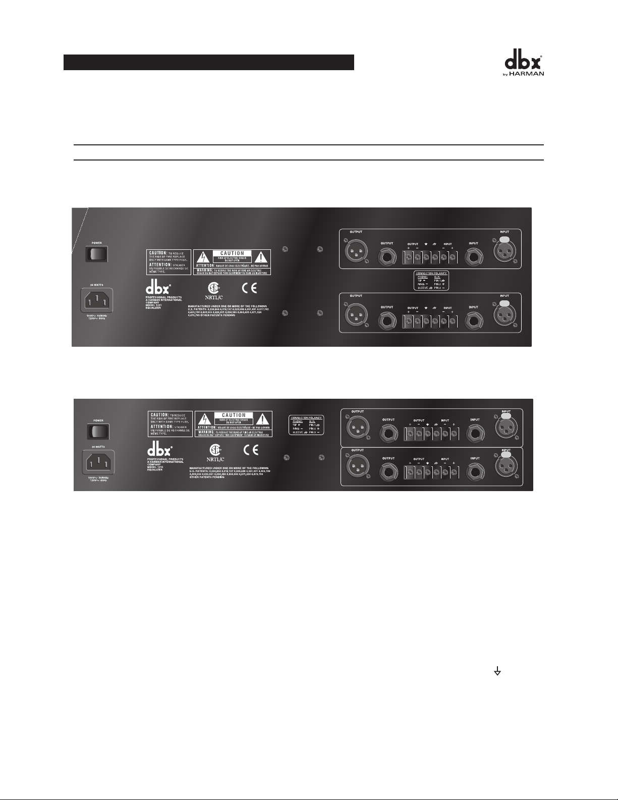
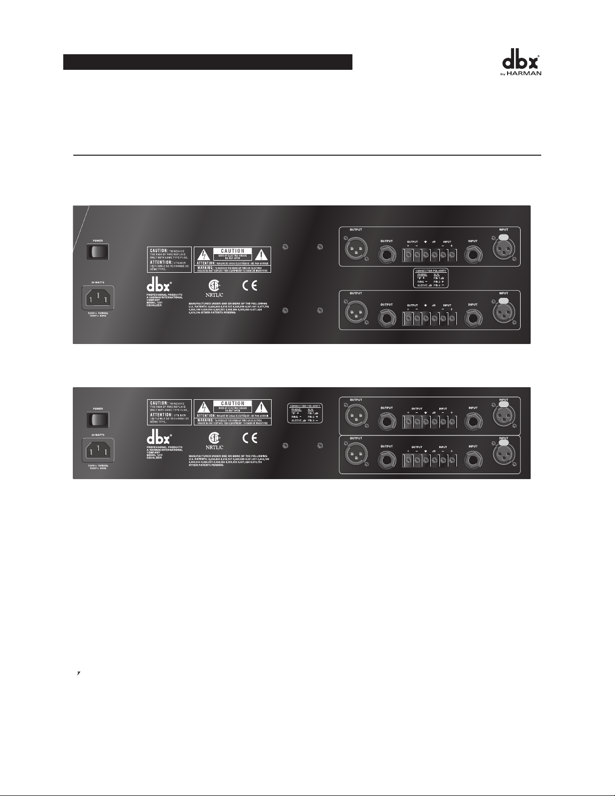
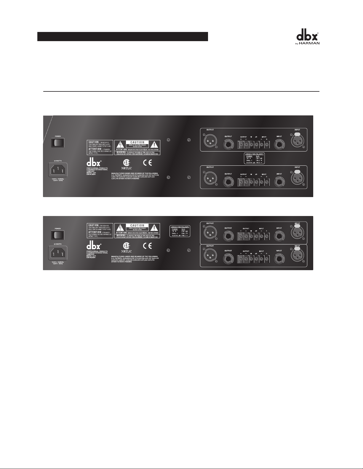
rear panel desCrIptIons
Rear Panels
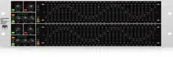
1231 - dual channel 31 band graphic equalizer
1215-dualchannel15bandgraphicequalizer
Power Switch: Switches the power on and off. Always make audio connections with the power switch in the OFF
position.
Power Cord Receptacle: Connects AC power to the equalizer.
Output Connectors:Threetypesofoutputconnectorsareprovidedforoutputconnections:maleXLRtypecon-
nectors,1/4"tip-ring-sleevephonejackconnectorsandabarrierstrip.
Input Connectors: Threetypesofinputconnectorsareprovidedforinputconnections:femalelockingXLRtype
connectors,1/4"tip-ring-sleevephonejackconnectors,andabarrierstrip.Themaximuminputlevelthattheequal-
izercanacceptis+22dBu(ref:0.775Vrms).
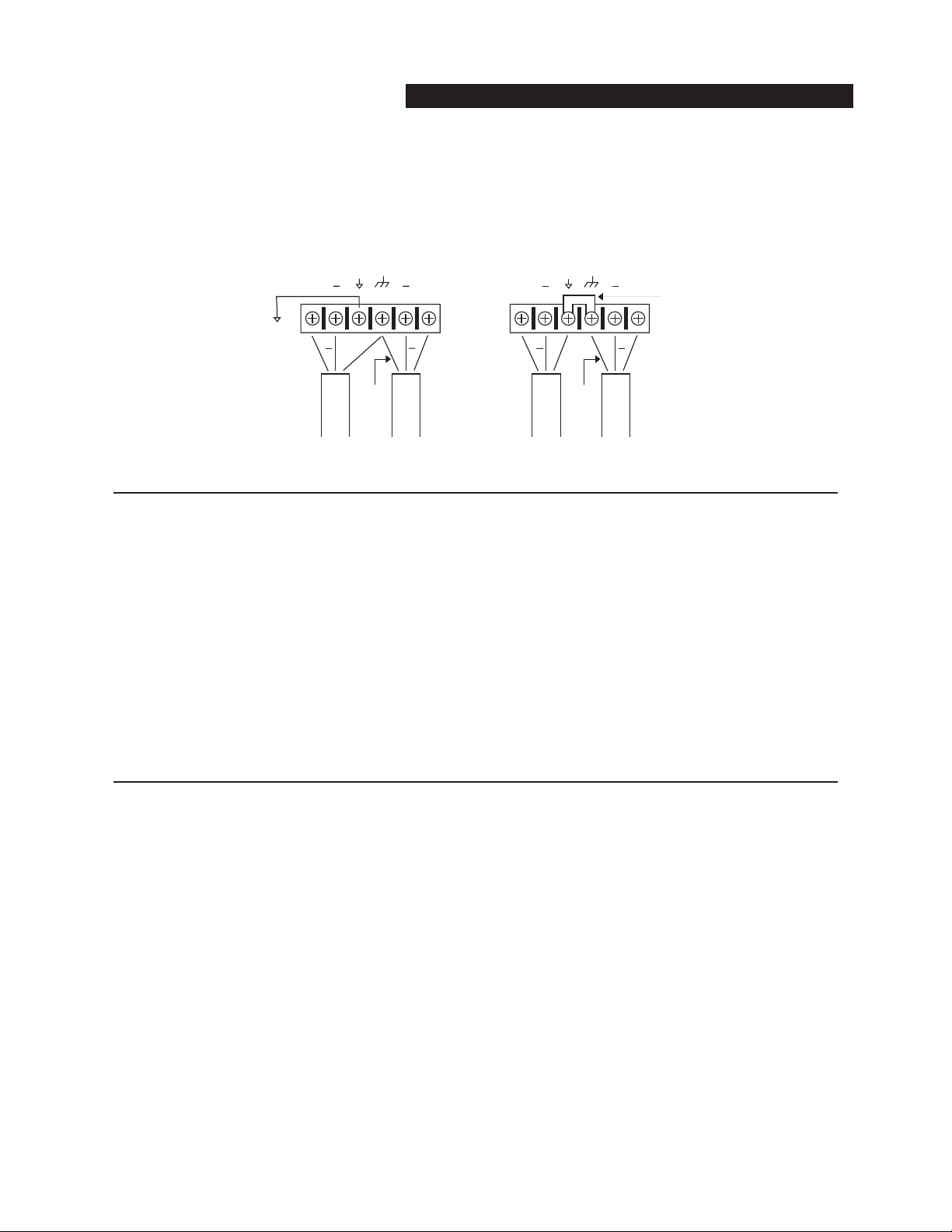
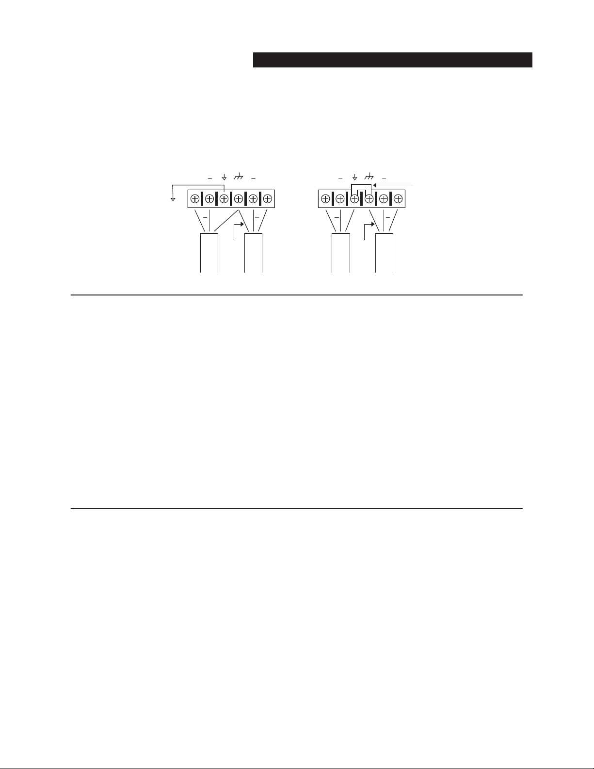
Byremovingthejumperconnectingthetwoscrewsonthebarrierstrip,thechassis
groundisseparatedfromthecircuitgroundoftheequalizer.Thisissometimesnecessarytoprevent“groundloops”
inasoundsystem.Whenliftingthegroundstrap,youmustmakeaconnectionfromthecircuitground(
++
+
++
+
++
Without Jumper in Place With Jumper in Place
jumper
optional
circuit
ground
chassis
ground
circuit
ground
chassis
ground
to system
ground
optional
WIRING CONNECTIONS WITH GROUND
Input
Cable
Output
Cable
Input
Cable
Output
Cable
)terminal
to some other ground point in your audio system in order for the equalizer to function properly.
4
OPERATION MANUAL
5
Wiring Connections With Ground
InstallatIon ConsIderatIons
The12SeriesEqualizersaredesignedfornominal+4dBulevels.Theequalizerscanbe
usedwitheitherbalancedorunbalancedsources,andtheoutputscanbeusedwitheitherbalancedorunbalanced
loads,providedthepropercablingisused.
A balanced line is defined as two-conductor shielded cable with the two center conductors carrying the same signal
but of opposite polarity when referenced to ground. An unbalanced line is generally a single-conductor shielded
cable with the center conductor carrying the signal and the shield at ground potential.
Theequalizerhasaninputimpedanceof40kΩbalancedand20kΩ unbalanced. This
makes the 12 Series Equalizers’ audio inputs suitable for use with virtually any low source impedance (under 2kΩ).
Theequalizer’soutputiscapableofdrivinga600Ωloadto+18dBu.Formaximum
humrejectionwithabalancedsource,avoidcommongroundingattheequalizer’sinputsandoutputs.Mostbal-
anced(3-conductor)cableshavetheshieldconnectedatbothends.Thiscanresultingroundloopswhichcause
hum.Ifhumpersiststrydisconnectingtheshieldononeormoreofthecablesinthesystem,preferablyattheinput
ofadevice,notattheoutput.
operatIon and applICatIon notes
Thedbx12SeriesGraphicEqualizersareusefulaudiosignalprocessingtoolsinsituationswhereprecisefrequency
control is required across the audible frequency spectrum.
When used with an audio spectrum analyzer the EQs can tune any acoustical environment -- from the studio to the
concerthall--tostopringing,increaseclarity,andflattentheoverallfrequencyresponseoftheenvironment.A
real-time spectrum analyzer or other types of audio environment analyzers are very useful in determining the
amount of equalization needed.
Insertthegraphicequalizerbetweenthesignalsource(usuallyamixer)andthepoweramplifiers(orthecrossoverif
thereisone).Adjustthelevelandequalizationasrequiredtoyieldthedesiredsystemresponse.Thelongthrowfad-
ers of the EQs allow very precise settings of the equalization for accurate equalization curves.
Foroptimumsignal-to-noiseresponse,thegainstructureofthesoundsystemmustbeproperlysetup.Eachcompo-
nentofthesoundsystemshouldbesetatitsnominaloperatinglevel,startingwiththefirstelementinthesystem,
usually a mixing console. Each element should be run at its nominal operating level in order to take advantage of
themaximumsignal-to-noisepropertiesofthatelement.Loudspeakeramplifiers,asthelastelementinthechain,
shouldbesetonlyasloudasnecessary,inordertoavoidinducingunnecessarynoiseintothesystem.
++
+
++
+
++
Without Jumper in Place With Jumper in Place
jumper
optional
circuit
ground
chassis
ground
circuit
ground
chassis
ground
to system
ground
optional
WIRING CONNECTIONS WITH GROUND
Input
Cable
Output
Cable
Input
Cable
Output
Cable
OPERATION MANUAL
12 SERIES GRAPHIC EQUALIZERS

teChnICal support / FaCtory servICe
The dbx 12 Series EQs are all solid-state products with components chosen for high performance and excellent reli-
ability.Eachunithasbeentestedandburned-inatthefactory.Noadjustmentofanytypeshouldberequired
throughout the life of the unit.
Ifcircumstancesarisewhichnecessitaterepair,werecommendthatyourEQbereturnedtothefactory.Thiscan
onlybedonebyreceivingaRETURNAUTHORIZATIONnumberfromdbxcustomerservice.
IfyourequiretechnicalsupportcontactCustomerService.Bepreparedtoaccuratelydescribetheproblem.Know
theserialnumberofyourunit(printedonastickerattachedtothechassisoftheunit).
Contact information is printed on the back cover of this manual.
6
OPERATION MANUAL

MODE D’EMPLOI
7
CORRECTEURS GRAPHIQUES SÉRIES 12
FRANÇAIS

ATTENTION
VEUILLEZ LIRE CE QUI SUIT :
CONSERVEZ CES INSTRUCTIONS
RESPECTEZ TOUTES LES CONSIGNES
SUIVEZ TOUTES LES INSTRUCTIONS
NETTOYEZ L’APPAREIL UNIQUEMENT AVEC UN LINGE HUMIDE.
NE BLOQUEZ PAS LES OUÎES DE VENTILATION. RESPECTEZ LES
CONSIGNES D’INSTALLATION DU FABRICANT.
N’INSTALLEZ PAS L’APPAREIL À PROXIMITÉ DE SOURCES DE
CHALEUR COMME DES RADIATEURS OU D D’AUTRES APPAREILS
SUSCEPTIBLES DE PRODUIRE DE LA CHALEUR (Y COMPRIS LES
AMPLIFICATEURS).
UTILISEZ UNIQUEMENT LES APPAREILS OPTIONNELS/
ACCESSOIRES RECOMMANDÉS PAR LE FABRICANT.
DÉBRANCHEZ CET APPAREIL DURANT LES ORAGES OU LORSQUE
VOUS NE L’UTILISEZ PAS PENDANT DE LONGUES PÉRIODES.
EAU ET HUMIDITÉ : L’appareil ne doit pas être utilisé à proximité de
liquides ou dans un endroit humide (salle de bain, sous-sol humide,
près d’une piscine, etc.). Veillez à ce qu’aucun objet ou liquide ne
pénètre dans l’appareil.
ALIMENTATION : L’appareil doit impérativement être connecté à un
réseau secteur de la tension correspondant à celle inscrite dans le
mode d’emploi ou sur l’appareil.
MISE À LA TERRE OU POLARISATION : Véillez à ne pas modifier la
mise à la terre ou la polarisation de l’appareil.
PROTECTION DU CORDON SECTEUR : Les cordons d’alimentation
doivent être placés de sorte qu’il soit impossible de marcher dessus.
Vérifiez que les cordons ne sont pas pincés ou écrasés par des
objets placés dessus ou à côté. Veillez au bon dégagement du cor-
don sur la prise secteur murale (ou multiprise) et sur l’appareil.
MAINTENANCE : Pour réduire les risques d’incendie et
d’électrocution, l’utilisateur doit uniquement effectuer sur l’appareil
les opérations indiquées dans le mode d’emploi. Les opérations de
maintenance doivent être confiées à des personnes qualifiées.
POUR LES APPAREILS ÉQUIPÉS D’UN FUSIBLE ACCESSIBLE :
Remplacez le fusible uniquement par un fusible du même type et du
même calibre.
TENSION D’ENTRÉE MULTIPLE : Cet appareil peut nécessiter un
cordon et/ou une prise différents, selon l’alimentation disponible à
l’installation. Connectez uniquement cet appareil au type
d’laimentation indiqué en face arrière de l’appareil. Pour réduire le
risque d’électrocution, confiez la maintenance à des personnes
qualifiées.
CONSIGNES DE SÉCURITÉ
APPAREILS POURVUS D’UN CORDON SECTEUR.
ATTENTION : CET APPAREIL DOIT ÊTRE RELIÉ À LA TERRE.
Les câbles du cordon secteur sont repérés par couleurs :
VERT et JAUNE - Terre BLEU - Neutre MARRON - Phase
Les couleurs utilisées par le cordon secteur de cet appareil peuvent être différen-
tes de celles utilisées par votre embase secteur :
•Lecâblecouleurverteetjaunedoitêtreconnectéauplotvertetjauneou
repéré par la lettre E (ou le symbole de la Terre).
•LecâblebleudoitêtreraccordéauplotNounoirdel’embase.
•Le câble marron doitêtre connecté auplot au plotL ou rouge de
l’embase secteur.
Cet appareil peut nécessiter l’utilisation d’un type différent de cordon secteur,
d’une liaison différente, voire les deux, selon la source utilisée lors de
l’installation. Si vous devez modifier la fiche, consultez un personnel qualifié
(code des couleurs indiqué dans le tableau ci-dessous). Le câble jaune/vert doit
être directement relié au châssis de l’appareil.
LIVE
E
NEUTRAL
EARTH GND
CONDUCTOR
L
N
BROWN
BLUE
GREEN/YEL
BLACK
Normal Alt
WIRE COLOR
WHITE
GREEN
ATTENTION : En cas de découplage de la terre, l’apparel peut présenter ou caus-
er des dysfonctionnements pouvant entraîner des accidents graves ou mortels
lors de contacts entre le châssis et la terre.
CAUTION
ATTENTION: RISQUE DE CHOC ELECTRIQUE - NE PAS OUVRIR
WARNING:
TO REDUCE THE RISK OF FIRE OR ELECTRIC
SHOCK DO NOT EXPOSE THIS EQUIPMENT TO RAIN OR MOISTURE
RISK OF ELECTRIC SHOCK
DO NOT OPEN
Les symboles internationaux illustrés ci-dessus signalent un danger élec-
trique potentiel. L’éclair indique la présence de tensions dangereuses dans
l’appareil. Le point d’exclamation indique à l’utilisateur la nécessité de con-
sulter le mode d’emploi.
Ces symboles vous indiquent que l’appareil ne contient aucune pièce sus-
ceptible d’être remplacée par l’utilisateur. Ne pas ouvrir l’appareil. N’essayez
pas de réparer l’appareil vous-mêmes. Consultez des personnes qualifiées.
L’ouverture du boîtier de l’appareil pour quelque raison que ce soit entraîne
instantanément la garantie constructeur. Ne mettez jamais l’appareil en con-
tact avec des liquides. Si du liquide est renversé sur l’appareil, mettez-le
immédiatement hors tension et confiez-le à un service de maintenance
compétent ou à votre revendeur. En cas d’orage, déconnectez l’appareil du
secteur.
CONSIGNES DE SÉCURITÉ IMPORTANTES
U.K. MAINS PLUG WARNING
A molded mains plug that has been cut off from the cord is unsafe. Discard the mains plug at a suitable disposal
facility. NEVER UNDER ANY CIRCUMSTANCES SHOULD YOU INSERT A DAMAGED OR CUT MAINS PLUG INTO A 13
AMP POWER SOCKET. Do not use the mains plug without the fuse cover in place. Replacement fuse covers can be
obtained from your local retailer. Replacement fuses are 13 amps and MUST be ASTA approved to BS1362.
CONSIGNES DE SÉCURITÉ IMPORTANTES
COMPATIBILITÉ
ÉLECTROMAGNÉTIQUE
Cet appareil est conforme aux caracté-
ristiques portée sur la déclaration de
conformité (ci-contre). L’utilisation
est soumise aux conditions suivantes :
•Cet appareil ne doit causer
aucune interférence dangereuse.
•Cet appareil doitacceptertoutes
les interférences reçues, y com-
pris celles susceptibles
d’engendrer un dysfonc-
tionnement.
Évitez d’utiliser cet appareil dans une
zone soumise à d’importants champs
électromagnétiques.
• Utilisez uniquement des câbles
blindés.
Nom du fabricant: dbx Professional Products
Adresse du fabricant: 8760 S. Sandy Parkway
Sandy, Utah 84070, USA
Déclare que le produit:
Nom du produit: dbx 1231, dbx 1215
Option du produit: Non communiquée
est conforme aux caractéristiques suivantes :
Sécurité: IEC 60065 -01+Amd 1
EMC: EN 55022:2006 (N/A; Analog Product)
IEC61000-4-2
IEC61000-4-3
IEC61000-4-4
IEC61000-4-5
IEC61000-4-6
IEC61000-4-8
IEC61000-4-11
Informations supplémentaires:
Ce produit est conforme aux exigences de:
Low Voltage Directive 2006/95/EC
EMC Directive 2004/108/EC.
RoHS Directive 2002/95/EC
WEEE Directive 2002/96/EC
En ce qui concerne la Directive 2005/32/EC et Règlement de
CE 1275/2008 du 17 décembre 2008, ce produit est conçu, est
produit, et est classifié comme Equipement Audio
Professionnel et est ainsi exempt de cette Directive.
Roger Johnsen
Director, Engineering
Signal Processing
8760 S. Sandy Parkway
Sandy, Utah 84070, USA
Date: November 19, 2010
Contact européen: Votre revendeur local dbx ou
Harman Music Group
8760 South Sandy Parkway
Sandy, Utah
84070 USA
(801) 566-8800
(801) 568-7583
DÉCLARATION DE CONFORMITÉ


taBle des MatIÈres
IntroductIon. . . . . . . . . . . . . . . . . . . . . . . . . . . . . . . . . . . . . . . . . . . . . . . . . . 12
InspectIon . . . . . . . . . . . . . . . . . . . . . . . . . . . . . . . . . . . . . . . . . . . . . . . . . . . . 12
R
églages . . . . . . . . . . . . . . . . . . . . . . . . . . . . . . . . . . . . . . . . . . . . . . . . . . . . . 12
connexIon du correcteur à votre système . . . . . . . . . . . . . . . . . . . . . . . . 13
descrIptIon des Faces arrIères. . . . . . . . . . . . . . . . . . . . . . . . . . . . . . . . . . . 14
InstallatIon . . . . . . . . . . . . . . . . . . . . . . . . . . . . . . . . . . . . . . . . . . . . . . . . . 15
notes sur l’utIlIsatIon et les applIcatIons . . . . . . . . . . . . . . . . . . . . . . . . 15
assIstance technIQue / servIce . . . . . . . . . . . . . . . . . . . . . . . . . . . . . . . . . . 16
TAB:E DES MATIERES
11
CORRECTEURS GRAPHIQUES SÉRIES 12
IntroduCtIon
Nousvousremercionsdelaconfiancequevousnoustémoignezenchoisissantuncorrecteurgraphiquedbx.Tous
lescorrecteursgraphiquesdbxsontdesappareilsmultifonctionnelsdehautequalité,conçuspourdélivrertoutela
souplesseetlapuissancenécessairesàuneutilisationprofessionnelle.Nousvousrecommandonsdeprendrele
tempsdelirecemoded’emploi.Ilvousfournittouteslesinformationsnécessaires,del’installationdusystèmeaux
applicationsd’égalisation.Lescorrecteurssérie12offrentlesfonctionssuivantes:
•Plaged’atténuation/accentuationcommutableentre±6dBet±15dB
•Entréesetsortiessymétriques
•ConnecteursXLR,surbornieretJackstéréo6,35mm
•Plagedegaind’entrée-12dB/+12dB
•Filtrepasse-haut18dB/octave40HzdetypeBessel
•Fonctiondedécouplagedemasse
•Transformateurinterned’alimentation
•FonctiondeBypassparrelai(misehorstension)avecdélaide2secondesàlamisesoustension.
InspeCtIon
Vérifiezquelepackducorrecteurcontientlesélémentssuivants:
•Appareildontlenumérodesériecorrespondàceluiindiquésurl’emballage
•Cordond’alimentation
•Moded’emploi
•Carted’enregistrement
•Quatrevisetrondellesdemontageenrack
Sil’undecesélémentsmanque,veuillezcontacterleserviceclientèledbxaunuméroindiquéaudosdecemode
d’emploi.
réglages
Faces avant
1231 - Correcteur graphique 31 bandes deux canaux
1215-Correcteurgraphique15bandesdeuxcanaux
12
MODE D’EMPLOI
1231
Graphic Equalizer
20 25 31.5 40 50 63 80 500400315250 1.6k1.25k1k800 5k4k3.15k2.5k 16k12.5k10k8k6.3k 20k2k630100 125 160 200
RANGE
OUTPUT
LEVEL (dBu)
LOW
CUT
EQ
BYPASS
INPUT
GAIN
dB
-12
0
+12
+/-6
+/-15
CLIP
+18+100-10
RANGE
OUTPUT
LEVEL (dBu)
LOW
CUT
EQ
BYPASS
INPUT
GAIN
dB
-12
0
+12
+/-6
+/-15
CLIP
+18+100-10
0
-15
+15
0
-15
+15
0
-6
+6
0
-6
+6
85-XXXX-X 1231 FRONT ART 7-12-99
RANGE
OUTPUT
LEVEL (dBu)
LOW
CUT
EQ
BYPASS
INPUT
GAIN
dB
-12
0
+12
+/-6
+/-15
CLIP
0
-6
+6
25 40 63 100 160 250 400 16k10k6.3k4k630 1k 1.6k 2.5k
+18+100-10
1215
Graphic Equalizer
85-XXXX-A0 1215 FRONT ART 7-15-99
0
-15
+15
RANGE
OUTPUT
LEVEL (dBu)
LOW
CUT
EQ
BYPASS
INPUT
GAIN
dB
-12
0
+12
+/-6
+/-15
CLIP
0
-6
+6
25 40 63 100 160 250 400 16k10k6.3k4k630 1k 1.6k 2.5k
+18+100-10
0
-15
+15

MODE D’EMPLOI
13
CORRECTEURS GRAPHIQUES SÉRIES 12
Ceréglagedétermineleniveaudusignalenentréeducorrecteur.Saplagederéglage
estde-12dBà+12dB.VouspouvezvisualisersoneffetsurleBargraphOUTPUTLEVEL.
Cettetouchepermetdecouperlasectiondecorrectiondutrajetdusignal(voirSynoptiqueen
page8).LatoucheBYPASSn’affecteaucunementleréglageINPUTGAINoulesfiltrespasse-hautLOWCUT.
Led EQ Bypass :CetteLEDrouges’allumelorsquelecorrecteurestenmodeBypass.NotezquelemodeBypass
affecteuniquementlasectiondecorrectiondescorrecteursséries12.LesréglagesINPUTGAIN et LOWCUT ne
sontpasmodifiéslorsquelecorrecteurestbypassé.
Cettetouchepermetdesélec-
tionnerlaplaged’accentuation/atténuationutiliséeparlecorrecteur:±6dBou±15dB.LaLedrouges’allume
lorsquelaplagede±15dBestsélectionnée.LaLedjaunes’allumelorsquelaplagede±6dBestsélectionnée.
Notezquelatouched’accentuation/atténuationestlégèrementenfoncéeafind’évitertouteactivationaccidentelle
susceptibled’endommagerlesautresélémentsdusystème.
Bargraph Output Level : CesquatresLedsindiquentleniveaudesortieducorrecteur.LaLedrougeestà3dB
avantl’écrêtageetportelavaleur+18dBu.Ellepermetdecontrôlerleniveauensortieducorrecteur,aprèstousles
autres traitements.
Led Clip : CetteLeds’allumelorsqu’unsignalinterneatteintunniveaude3dBavantécrêtage,cequiseproduit
lorsque:1)leniveaudusignald’entréeestplusélevéque+22dBu,2)unniveauexcessifestappliquéauréglagedu
gaind’entrée,ou3)uneaccentuationexcessiveestappliquéeàl’aidedescurseursdefréquences.
Chacundecescurseursaccentueouatténuelafréquencequiluiestaffectée
dansuneplagede±6dBou±15dB,selonlapositiondelatoucheRANGEd’accentuation/atténuation.Lorsque
touslescurseurssontenpositioncrantéecentrale,lasortieducorrecteurestplate.Lescentresdesbandesde
fréquencesdu1231sontespacéespardesintervallesstandardsd’untiersd’octave(normeISO),alorsquelescen-
tresdesbandesdefréquencedu1215sontespacéspardesintervallesdedeuxtiersd’octavestandards(normeISO).
LatoucheLOW-CUTinsèreouretiredutrajetdusignallefiltrepasse-hautde
18dB/octave40HzdetypeBessel.Quandelleestenfoncée,lefiltrepasse-hautestinsérédansletrajetdusignal.
ConnexIon du CorreCteur à votre systÈMe
Lescorrecteursséries12sontéquipésd’entréesetdesortiessymétriquespouvantêtreutiliséesavectoutappareilà
niveaulignesymétriqueouasymétrique.Pourobtenirdesinformationsplusspécifiquessurlespossibilitésde
câblage,veuillezvousreporteràlasectionintituléeInstallation, en page 5.
Pourconnecterlecorrecteuràvotresystème,consultezlesinstructions:
Installezlecorrecteurdansunrackàl’aidedesvisspécialesfournies.Ilnedoitpasêtremontésurousousun
appareilgénérantunechaleurexcessive.Latempératureambiantenedoitpasexcéder45°Clorsquevousutili-
sezl’appareil.Bienquelechâssisdel’appareilsoitblindécontrelesHFetlesinterférencesmagnétiques,vous
devezéviterleschampstropimportantsdeHFoud’interférencesélectromagnétiques.
Les3typesdeconnecteursdesentrées/sortiespermettentdesconnexionssymétriquesouasymétriques.
L’utilisationdeplusd’unconnecteuràlafoispourlesentréespeutasymétriserleslignessymétriques,causer
desannulationsdephase,descourt-circuits,ouendommagerlesappareilsreliésaucorrecteur.Vouspouvezuti-
liserplusieurssortiessimultanémenttantquelachargetotaleàsupérieureà600Ω.
Note: Réduisez les niveaux audio des amplis de puissance pour modifier le réglage de cette touche afin d’éviter de générer des transitoires audi-
bles.
Connectezlecordond’alimentationàl’embasesecteurenfacearrièreducorrecteur.Branchezlecordon
d’alimentationàunepriseadéquate,éloignéedeslignesaudio.L’appareilpeutêtreactivé/désactivéàl’aidede
l’interrupteursecteurdelafacearrièreoudelinterrupteurdelaprisesecteur.Commelescorrecteursdesséries
12consommentrelativementpeu,vouspouvezleslaissercontinuellementsoustension.
desCrIptIon des FaCes arrIÈres
Faces arrières
1231 - Correcteur graphique 31 bandes deux canaux
1215-Correcteurgraphique15bandesdeuxcanaux
Interrupteur Power : Permetdemettrel’appareilsoustensionouhorstension.Effectueztoujourslesconnexions
lorsque l’appareil est hors tension (position OFF).
Permetderelierl’appareilausecteur.
Connecteurs Output :L’appareilestéquipédetroistypesdeconnecteursdesortie;typeXLRmâle,Jackstéréo
6,35mmetsurbornier.
Connecteurs Input : L’appareilestéquipédetroistypesdeconnecteursd’entrée:typeXLRfemelleàverrouil-
lage,Jackstéréo6,35mmetsurbornier.Leniveaud’entréemaximumquepeutaccepterlecorrecteurestde+22
dBu(réf.:0,775Veff.).
Enretirantlefilcavalierquirelielesdeuxvisdubornier,lamassemécaniqueestdécou-
pléedelamasseélectriqueducorrecteur.Celas’avèreparfoisnécessairepouréviterlesbouclesdemassedansun
systèmesonore.Lorsquevousretirezlefildemasse,vousdevezconnecterlabornedemasseélectrique
(
++
+
++
+
++
Without Jumper in Place With Jumper in Place
jumper
optional
circuit
ground
chassis
ground
circuit
ground
chassis
ground
to system
ground
optional
WIRING CONNECTIONS WITH GROUND
Input
Cable
Output
Cable
Input
Cable
Output
Cable
)àunautrepointdemassedevotresystèmeaudiopourquelecorrecteurfonctionnecorrectement.
14
MODE D’EMPLOI
Connexions à la masse
InstallatIon
Lescorrecteursséries12sontconçuspourdesniveauxnominaux+4dBu.Lescor-
recteurspeuventêtreutilisésavecdessourcessymétriquesouasymétriquesetlessortiespeuventêtreutiliséesavec
deschargessymétriquesouasymétriquesavecuncâblageadéquat.
Unelignesymétriqueestvéhiculéeparcommeuncâbleblindédeuxconducteursdontlesdeuxconducteurscen-
trauxtransportentlemêmesignalmaisdepolaritéopposéelorsqu’ilssontréférencésàlamasse.Uneligneasymé-
triqueestgénéralementvéhiculéeparuncâbleblindésimpleconducteur,dontleconducteurcentraltransportele
signal et le blindage at ground potential.
Lecorrecteurprésenteuneimpédanced’entréede40kΩsymétriqueet
20kΩasymétrique.Lesentréesaudiodescorrecteursséries12sontdoncadaptéesàpratiquementtouteslessources
basseimpédance(sous2kΩ).
Lasortieducorrecteurestcapabledegérerunechargede600Ωà+18dBu.
Pourunrejetmaximumduronflementavecunesourcesymétrique,évitezderéférencerlesentréesetlessortiesdu
correcteuràlamêmemasse.Leblindagedelaplupartdescâblessymétriques(3conducteurs)estconnectéauxdeux
extrémités.Celapeutentraînerdesbouclesdemasseetdoncduronflement.Sileronflementpersiste,essayezde
déconnecterleblindaged’unoudeplusieurscâbles,depréférenceàl’entréed’unappareil(nonàlasortie).
notes sur l’utIlIsatIon et les applICatIons
Lescorrecteursgraphiquedesséries12sontdesoutilstrèspratiquesdansletraitementdessignauxaudio:ilsper-
mettentuncontrôleprécisdesfréquencessurlespectreaudible.
Lorsqu’ilssontutilisésavecunanalyseurdespectreaudio,lescorrecteurssontsusceptiblesd’accordern’importe
quelenvironnementacoustique(dustudioàlasalledeconcert)-ilspeuventatténuerlarésonance,augmenterla
clartéethomogénéiserlabandepassanteglobaledel’environnement.L’utilisationd’unanalyseurdespectreen
tempsréeloud’autrestypesd’analyseursd’envionnementaudioesttrèspratiquepourdéterminerlaquantitédecor-
rectionnécessaire.
Insérezlecorrecteurgraphiqueentrelasourcesonore(généralementuneconsoledemixage)etlesamplisdepuis-
sance(oulefiltreactif,s’ilyenaun).Déterminezleniveauetlacorrectionnécessairesàlaréponsesouhaitée.Les
Fadersàlonguecoursedescorrecteurspermettentdesréglagestrèsefficacespourdescourbesd’égalisationprécis-
es.
Pourobtenirunrapportsignal/bruitoptimum,lastructuredegaindusystèmedoitêtrecorrectementconfigurée.
Chaqueélémentdusystèmesonoredoitêtrerégléàsonniveaud’utilisationnominal(dèslepremierélémentdusys-
tème,quiestgénéralementuneconsoledemixage).Chaqueélémentdoitêtreutiliséàsonniveaudefonctionnement
nominalafind’obtenirsonmeilleurrapportsignal/bruit.Lesamplificateurs,derniersélémentsdelachaînedoivent
êtreréglésàunniveauoptimal,pournepasinduiredebruitindésirable.
MODE D’EMPLOI
15
CORRECTEURS GRAPHIQUES SÉRIES 12
++
+
++
+
++
Without Jumper in Place With Jumper in Place
jumper
optional
circuit
ground
chassis
ground
circuit
ground
chassis
ground
to system
ground
optional
WIRING CONNECTIONS WITH GROUND
Input
Cable
Output
Cable
Input
Cable
Output
Cable

assIstanCe teChnIQue / servICe
Lescorrecteursséries12dbxsonttousdesappareilsàtransistorsavecdescomposantsspécialementsélectionnés
pourleurexcellentequalitéetleurfiabilité.Chaqueappareilaétémissoustension,testéetrégléenusine,etne
devraitdoncnécessiteraucunréglageinterneduranttoutesaduréedevie.
Siuneréparations’avéraitnécessaire,nousvousrecommandonsderenvoyerl’appareilàl’usine.Vousdevezpréal-
ablementavoirdemandévotrenumérod’autorisationderetour(RETURNAUTHORIZATION)auserviceclientèle
de dbx.
Lorsquevouscontactezlesservicesdemaintenance,préparez-vousàdécrireleproblèmedemanièrepréciseetà
donnerlenumérodesériedevotreappareil(imprimésurunautocollantplacésousl’appareil).
Lesinformationsconcernantlesservicessontimpriméesaudosdecemoded’emploi.
16
MODE D’EMPLOI

BEDIENUNGSANLEITUNG
17
GRAPHISCHE EQUALIZER SERIEN 12
DEUTSCH
®
®
®
®
®
®
WARNUNG
FÜR IHRE SICHERHEIT,BITTE LESEN SIE FOLGENDES
VERWAHREN SIE DIESE ANGABEN
BEACHTEN SIE ALLE WARNUNGEN
FOLGEN SIE DEN ANWEISUNGEN
SÄUBERN SIE AUSSCHLIEßLICH MIT EINEM FEUCHTEN TUCH
VERSPERREN SIE KEINE DER LÜFTUNGSÖFFNUNGEN, BAUEN SIE
NACH ANGABEN DES HERSTELLERS AUF.
VERMEIDEN SIE EINEN AUFBAU IN DER NÄHE VON
HITZEQUELLEN,WIE HEIZKÖRPER, OFEN ODER ANDERE GERÄTE
(VERSTÄRKER MIT EINGESCHLOSSEN), DIE WÄRME
AUSSTRAHLEN.
BENUTZEN SIE NUR VOM HERSTELLER AUFGEFÜHRTES
ZUBEHÖR.
ZIEHEN SIE DEN STECKER WÄHREND GEWITTER ODER WENN
DAS GERÄT ZEITWEISE UNBENUTZT BLEIBT HERAUS
WASSER UND FEUCHTIGKEIT Das Gerät sollte nicht in der Nähe
von Wasser benutzt werden (z.B. in der Nähe einer Badewanne,
eines Waschbeckens, Spülbeckens, Waschzubers, in einem
feuchten Keller oder in der Nähe des Swimming-pools usw.). Es
sollte darauf geachtet werden, daß keine Flüssigkeit durch die
Öffnungen in die Anlage fließt.
VERSORGUNGSNETZ: Das Gerät sollte nur an einem im Handbuch
oder auf dem Gerät angegebenen Stromversorgung angeschlossen
werden.
ERDUNG ODER POLARISATION: Die Erdung oder Polarisation des
Gerätes sollte nicht verändert werden.
NETZKABELSCHUTZ: Stromversorgungskabel sollten so gelegt
werden, daß niemand auf sie tritt oder sie nicht durch auf oder
gegen sie gestellte Gegenstände eingeklemmt werden. Achten Sie
besonders auf die Kabelstecker und die Stelle, an der die Kabel aus
dem Gerät treten.
WARTUNG: Zur Verminderung der Gefahren soll der Benutzer nur
den im Handbuch beschriebenen Betrieb vornehmen. Jede weitere
Wartungsarbeit sollte qualifiziertem Kundendienstpersonal überlas-
sen werden
FÜR GERÄTE MIT VON AUßEN ZUGÄNGLICHEM
SICHERUNGSKASTEN: Sicherung gleicher Art und gleichen Wertes
austauschen.
VERSCHIEDENE NETZSPANNUNGEN : Dieses Gerät benötigt mögli-
cherweise mehrere Netzkabel oder
-stecker, oder beides, je nach Land. Verbinden Sie dieses Gerät nur
mit dem auf der Rückseite angegebenen Stromnetz an. Zur
VErminderung der Brand- oder Stromschlaggefahr, wenden Sie sich
an fachmännisches Kundenpersonal.
CONSIGNES DE SÉCURITÉ
A
GERÄT MIT EINEM NETZKABEL AUSGERÜSTET IST.
WARNUNG: DIESES GERÄT MUSS GEERDET WERDEN.
Die in dem Versorgungskabel befindlichen Drähte sind nach den folgenden Kodes gefärbt:
GRÜN und GELB - Erde BLAU - Neutral BRAUN - Phase
Wenn die in dem Versorgungskabel des Gerätes befindlichen Drähte nicht den farbigen
Markierungen, die die Anschlüße Ihres Steckers bestimmen, entsprechen, verfahren Sie wie
gefolgt:
•Dergrün-undgelbfarbigeDrahtmußandemmitdemBuchstabenE
gekennzeichten Anschluß, oder an denjenigen mit dem Erdesymbol, oder an dem
grün- oder grün- und gelbgefärbten Anschluß angeschlossen werden.
•DerblaufarbigeDrahtmußandemmitdemBuchstabenNgekennzeichten
oder schwarzgefärbten Anschluß angeschlossen werden.
•DerbraunfarbigeDrahtmußandemmitLgekennzeichtemoderrotgefärbtem
Anschluß angeschlossen werden.
Je nach Versorgungsnetz, könnte die Anlage ein anderes Kabel oder einen anderen Stecker oder
beides benötigen. Überlassen Sie das Auswechseln des Steckers qualifiziertem
Kundendienstpersonal, das sich auf die unten aufgeführte Tabelle beziehen wird. Der grün- und
gelbfarbige Draht sollte direkt an das Gerätechassis angeschlossen werden.
Phase
Neutral
Erde
LEITER
L
N
Braun
Blau
Grün/Gelb
Schwarz
DRAHTFARBE
Weiß
Grün
WARNUNG: Wenn die Erdung desaktiviert ist, können Störungen in dem angeschlossenen Gerät
oder System eine starke Spannung zwischen Grund und Chassis hervorrufen. Die gleichzeitige
Berührung der Erde und des Chassis können zu schweren Verletzungen oder Tod führen.
CAUTION
ATTENTION:
RISQUE DE CHOC ELECTRIQUE - NE PAS OUVRIR
WARNING:
TO REDUCE THE RISK OF FIRE OR ELECTRIC
SHOCK DO NOT EXPOSE THIS EQUIPMENT TO RAIN OR MOISTURE
RISK OF ELECTRIC SHOCK
DO NOT OPEN
Die oben angezeigten Symbole sind weltweit anerkannt gegen mögliche Gefahren
elektrischer Geräte zu warnen. Der Blitz mit Pfeilspitze in einem gleichseitigem
Dreieck deutet auf gefährliche Spannungen im Gerät. Das Ausrufezeichen im gleich-
seitigen Dreieck gibt dem Benutzer zu verstehen, daß die Kenntnisnahme des
Handbuches erforderlich ist.
Diese Warnsymbole zeigen an, daß im Inneren des Gerätes keine für den Benutzer
nützlichen Teile sind. Öffnen Sie nicht das Gerät. Versuchen Sie nicht das Gerät
selbstständig zu unterhalten. Alle Wartungsarbeiten sollten qualifiziertem
Kundendienstpersonal überlassen werden. Die Öffnung des Rahmengestells hat die
Nichtanwendung derHerstellergarantie zur Folge. Halten Sie das Gerät im Trockenen.
Wenn Flüssigkeit auf das Gerät vergossen wird, schalten Sie es sofort aus, und brin-
gen Sie es zur Wartung zu einem Fachhändler. Schalten Sie das Gerät bei Sturm zur
Beschädigungvorbeugung aus
.
WICHTIGE SICHERHEITSVORKEHRUNGEN
U.K. MAINS PLUG WARNING
A moulded mains plug that has been cut off from the cord is unsafe. Discard the mains plug at a suitable disposal
facility. NEVER UNDER ANY CIRCUMSTANCES SHOULD YOU INSERT A DAMAGED OR CUT MAINS PLUG INTO A 13
AMP POWER SOCKET. Do not use the mains plug without the fuse cover in place. Replacement fuse covers can be
obtained from your local retailer. Replacement fuses are 13 amps and MUST be ASTA approved to BS1362.
WICHTIGE SICHERHEITSVORKEHRUNGEN
ELEKTROMAGNETISCHE
KOMPATIBILITÄT
Dieses Gerät richtet sich nach den
Produktklauseln der
Übereinstimmungs-erklärung : Der
Betrieb untersteht den folgenden
zwei Bedingungen:
•dieseVorrichtungdarfkeine
schädliche Interferenz verursachen,
und
•dieseVorrichtungmußjede
Interferenz empfangen, selbst dieje-
nigen, die eine unerwünschte
Wirkung haben.
Der Betrieb dieses Gerätes sollte in
starken elektromagnetischen
Feldern vermieden werden.
•Nurgekapselte
Vernetzungskabel benutzen.
Name des Herstellers: dbx Professional Products
Adresse des Herstellers: 8760 S. Sandy Parkway
Sandy, Utah 84070, USA
erklärt, daß das Produkt:
erklärt, daß das Produkt: dbx 1231, dbx 1215
Ausstattungen des Produktes: keine Angaben
sich den folgenden Produktangaben angleicht:
Sicherheit: IEC 60065 -01+Amd 1
EMC : EN 55022:2006 (N/A; Analog
Product)
IEC61000-4-2
IEC61000-4-3
IEC61000-4-4
IEC61000-4-5
IEC61000-4-6
IEC61000-4-8
IEC61000-4-11
Zusätzliche Informationen:
Dieses Produkt entspricht den:
Low Voltage Directive 2006/95/EC
EMC Directive 2004/108/EC.
RoHS Directive 2002/95/EC
WEEE Directive 2002/96/EC
Mit Beachtung zu Direktive 2005/32/EC und EC
Regelung 1275/2008 von 17 Dezember 2008, ist
dieses Produkt entworfen, ist hergestellt, und ist
als Berufliche Tongeräte klassifiziert und ist fol
glich frei von dieser Direktive.
Roger Johnsen
Director, Engineering
Signal Processing
8760 S. Sandy Parkway
Sandy, Utah 84070, USA
Date: November 19, 2010
Kontakt in Europa: Ihr nächster Digitech Fachhandel oder
Kundendienst oder
Harman Music Group
8760 South Sandy Parkway
Sandy, Utah
84070 USA
(801) 566-8800
(801) 568-7583
ÜBEREINSTIMMUNGS- ERKLÄRUNG


InhaltsverZeIChnIs
eInleItung . . . . . . . . . . . . . . . . . . . . . . . . . . . . . . . . . . . . . . . . . . . . . . . . . 22
ÜBerprÜFung . . . . . . . . . . . . . . . . . . . . . . . . . . . . . . . . . . . . . . . . . . . . . . 22
eInstellungen. . . . . . . . . . . . . . . . . . . . . . . . . . . . . . . . . . . . . . . . . . . . . 22
anschlu
ss des eQualIZers an Ihr system. . . . . . . . . . . . . . . . . 23
BeschreIBung der rÜckseIten . . . . . . . . . . . . . . . . . . . . . . . . . . . . 24
InBetrIeBnahme . . . . . . . . . . . . . . . . . . . . . . . . . . . . . . . . . . . . . . . . . . . 25
Bemerkungen Zur BenutZung und anWendung . . . . . . . . . 25
technIsche hIlFe / kundendIenst . . . . . . . . . . . . . . . . . . . . . . . . . 26
INHALTSVERZEICHNIS
21
GRAPHISCHE EQUALIZER SERIEN 12
eInleItung
WirgraturienIhnenzumErwerbeinesdbxGraphicEqualizer.AlledbxGraphicEqualizersindsehrleistungsfähige,
multi-funktionelleGeräte,dieentwickeltwurden,umdievondenBenutzerngewünschteUmgänglichkeitund
Leistungzubesitzen.WirempfehlenIhnen,sicheinenMomentZeitzunehmen,umdieBedienungsanleitung
durchzulesen.DieseenthältAngaben,dieIhnenzurInbetriebnahmedesSystemsundEQ-Bedienungbehilflichsein
werden.DieEqualizerSerien12besitzenfolgendeMerkmale:
•Zwischen±6dBund±15dBeinstellbarerAnhebung-/Absenkungsbereich
•SymmetrierteEin-undAusgänge
•XLR-,Klemmenleisten-und3,65mmStereo-Klinkenverbinder
•-12dB/+12dBEingangs-GainStufen
•18dB/Oktave40Bessel-Hochpaßfilter
•Masse-Entkopplungsfunktion
•InternerStromtransformator
•Relais-BypassFunktion(Stromausschaltung)miteinerZeitverzögerungderEinschaltung
von 2 Sekunden....
ÜBerprÜFung
UberprüfenSie,daßdieEqualizer-Verpackungfolgendesbeinhaltet:
•EqualizermitderaufderPackungangegebeneSeriennummer
•Netzkabel
•Bedienungsanleitung
•Eintragungskarte
•VierSchraubenundDichtungsringezumRack-Aufbau
WenneinesdieserTeilefehlensollte,wendenSiesichanIhrendbx-Kundendienst,dessenNummeraufder
RückseitedieserBedienungsanleitungangegebenist.
eInstellungen
Vorderseiten
1231-Zwei-Kanal31BandGraphischerEqualizer
1215-Zwei-Kanal15BandGraphischerEqualizer
22
BEDIENUNGSANLEITUNG
RANGE
OUTPUT
LEVEL (dBu)
LOW
CUT
EQ
BYPASS
INPUT
GAIN
dB
-12
0
+12
+/-6
+/-15
CLIP
0
-6
+6
25 40 63 100 160 250 400 16k10k6.3k4k630 1k 1.6k 2.5k
+18+100-10
1215
Graphic Equalizer
85-XXXX-A0 1215 FRONT ART 7-15-99
0
-15
+15
RANGE
OUTPUT
LEVEL (dBu)
LOW
CUT
EQ
BYPASS
INPUT
GAIN
dB
-12
0
+12
+/-6
+/-15
CLIP
0
-6
+6
25 40 63 100 160 250 400 16k10k6.3k4k630 1k 1.6k 2.5k
+18+100-10
0
-15
+15
1231
Graphic Equalizer
20 25 31.5 40 50 63 80 500400315250 1.6k1.25k1k800 5k4k3.15k2.5k 16k12.5k10k8k6.3k 20k2k630100 125 160 200
RANGE
OUTPUT
LEVEL (dBu)
LOW
CUT
EQ
BYPASS
INPUT
GAIN
dB
-12
0
+12
+/-6
+/-15
CLIP
+18+100-10
RANGE
OUTPUT
LEVEL (dBu)
LOW
CUT
EQ
BYPASS
INPUT
GAIN
dB
-12
0
+12
+/-6
+/-15
CLIP
+18+100-10
0
-15
+15
0
-15
+15
0
-6
+6
0
-6
+6
85-XXXX-X 1231 FRONT ART 7-12-99

Input Gain Regler: DieserReglerbestimmtdenSignalpegelamEingangdesEqualizers.DerEinstellungsbereich
reichtvon-12dBbis+12dB.SeinenEffektistaufdemBargraphOUTPUTLEVELsichtbar.
SchaltetdenEqualizer-AbschnittausdemSignalwegaus(SieheBlockschaltbildaufSeite8).
DieaktivierteBypass-TastewirktnichtaufdieEinstellungenINPUTGAINoderdieHochpaßfilterLOWCUT.
DieseroteLEDleuchtet,wennderEQimBypass-Moduseingestelltist.DieBypass-Funktion
wirktnuraufdengraphischenEqualizer-AbschnittderEqualizerSerien12.DerEinstellungINPUTGAINunddie
HochpaßfilterLOWCUTbleibenbeiaktivierterBYPASS-Tasteunberührt.
DieTasteermöglicht,die
Anhebung-/Absenkungswerte,diederEqualizerverwendet,einzustellen:±6dBoder±15dB.DieroteLEDleuchtet,
wennder±15dB-Bereicheingestelltist.DiegelbeLEDleuchtet,wennder±6dB-Bereicheingestelltist.AchtenSie
darauf,daßdieAnhebung/Absenkungstasteleichteingelassenist,umjedeunbeabsichtlicheAktivierungzuver-
meiden,diedieanderenTeiledesSystemsbeschädigenkönnte.
DiesevierLEDzeigendenAusgangspegeldesEqualizersan.DieroteLEDbefin-
detsichbei3dBunterhalbderÜbersteuerungsgrenzeundbesitztdenWert+18dB.SieerlaubtdenAusgangspegel
desEqualizerszubestimmen,nachallenanderenVerarbeitungen.
Clip LED: DieseLEDleuchteauf,wenneininternesSignal3dBvorderÜbersteuerungerreicht.Daskommtvor,
wenn:1)dasEingangssignalleistungsfähigerals+22dBist,2)einüberschüssigerPegeldurchdenEingangs-Gain
Reglereingestelltwirdoder3)eineübermäßigeAnhebungdurchdieFrequenz-Schiebereglereingestelltwird.
JederdieserSchiebereglerhebtodersenktdieihmzugeteilteFrequenzin
einemBereichvon±6dBoder±15dBanoderab,jenachPositionderRANGEAnhebung/Absenkungstaste.Wenn
alleSchiebereglerindermittlerenRaster-Positionsind,istderAusgangspegeldesEqualizersflach.Die
Frequenzbandmittendes1231besitzeneinenAbstandvon1/3OktaveninStandard-Intervallen,währenddie
Frequenzbandmittendes1215einenAbstandvon2/3OktaveninStandard-Intervallenbesitzen.
DieLOWCUTTastefügtinoderziehtausdemSignalwegden18dB/Oktave40Bessel-
Hochpaßfilter.WenndieTasteeingedrücktist,istderHochpaßfilterindenSignalwegeingefügt.
ansChluss des eQualIZers an Ihr systeM
DerEqualizeristmitsymmetriertenEin-undAusgängenbesetzt,diemitjedemsymmetriertenoderasymmetri-
schenLine-PegelGerätverwendetwerdenkönnen.WeiteresüberdieAnschlußmöglichkeiten,findenSieunter
„Inbetriebnahme“aufSeite6.ZurVerbindungdesEqualizersmitIhremTonsystem,unternehmenSiefolgendes:
InstallierenSiedieEqualizerineinRackmitdenbeiliegendenSchrauben.Erkannnichtober-oderunterhalb
einesGerätes,daszuvielWärmeausstrahlt,aufgebautwerden.BeiBetriebdesGerätessolltedieRaum-
Temperaturnicht45°Cüberschreiten.ObwohldasGeräte-ChassisgegenHF-Frequenzenundelektro-magne-
tischeInterferenzengeschütztist,solltenstarkeHF-oderelektromagnetischeFeldervermiedenwerden.
AlledreiVerbinder-ArtenderEin-undAusgängekönnenfürsymmetrierteoderasymmetrischeAnschlüßever-
wendetwerden.DieBenutzungvonmehralseinenVerbindergleichzeitigfürdieEingänge,kanndiesymmetri-
ertenLeitungenumsymmetrieren,Phasenaufhebungenhervorrufen,sowieKurzschlüßeoderBeschädigungen
derandemEqualizerangeschlossenenGeräte.SiekönnenmehrereAusgängegleichzeitigbenutzen,solange
dieGesamt-Last600Wüberschreitet.
Bemerkung: Vermindern Sie bei Einstellungsveränderung dieser Taste die Audio-Pegel der Leistungsverstärker, um zu vermeiden , hörbare momentane Überspannungen hervorzurufen.
VerbindenSiedasNetzkabelmitderNetzbuchseaufderRückseitedesEqualizers.SchließenSiedas
NetzkabelaneinengeeignetenNetzanschluß,weitvonAudio-Leitungenentfernt.DasGerätwirdmitdemauf
BEDIENUNGSANLEITUNG
23
GRAPHISCHE EQUALIZER SERIEN 12
derRückseitebefindlichenNetzschalteroderdemSchalterandemNetzanschlußein-undausgeschaltet.Da
dieEqualizerSerein12relativwenigEnergieverbrauchen,könnensieeingeschaltetbleiben.
BesChreIBung der rÜCKseIten
Rückseiten
1231-Zwei-Kanal31BandGraphischerEqualizer
1215-Zwei-Kanal15BandGraphischerEqualizer
SchaltetdasGeräteinundaus.UnternehmenSiedieAudio-Verbindungenimmer,wenndas
Gerätausgeschaltetist.
Erlaubt,dasGerätmiteinenNetzanschlußzuverbinden.
DasGerätistmitdreiVerbinder-Artenbesetzt:XLR-Stecker(männlich),3,65mmStereo-
KlinkensteckerundmitKlemmleiste.
DasGerätistmitdreiVerbinder-Artenbesetzt:XLR-Stecker(weiblich)mitSperrung,3,65mm
Stereo-KlinkensteckerundmitKlemmleiste.DermaximaleEingangspegel,denderEqualizererlaubt,ist+22dBu
(Ref.:0,775Vrms).
WennderJumper,derdiezweiSchraubenderKlemmleisteverbindet,entfernt
wird,istdieChassis-MassevonderSchaltkreis-MassedesEqualizersentkoppelt.SievermeidensoeinMasse-
schleifenineinemTonsystem.WennSiedenMasse-Drahtentfernen,müssenSiedieLeistederSchaltkreis-Masse
aneinenanderenMasse-PunktIhresAudio-Systemsanschließen,damitderEqualizerrichtigbetriebenwerden
kann.
24
BEDIENUNGSANLEITUNG

Anschluß an die Masse
InBetrIeBnahMe
DieEqualizerSerie12sindfürNominalpegelvon+4dBuentwickeltworden.
DieEqualizerkönnenmitsymmetriertenoderasymmetrischenQuellenbenutztwerden,unddieAusgängekönnen
mitsymmetriertenoderasymmetrischenLastenbenutztwerden,wenndiegeeignetenKabelverwendenwerden.
EinesymmetrierteÜbertragungisteinzweiadrigesabgeschirmtesKabel,dessenzweimittlerenAderndasgleiche
Signalführen,abermitentgegengesetzterPolarität,wennsiesichaufdieMassebeziehen.Eineasymmetrische
ÜbertragungistnormalerweiseeineinadrigesabgeschirmtesKabel,diemittlereAderdasSignalführt,unddie
AbschirmungdieMassenverbindungdarstellt.
DerEqualizerbesitzteineEingangsimpedanzvon40Wsymmetriertund20kW
asymmetrisch.DieAudio-EingängederEqualizerSerie12sinddeshalbfastallenNiedrigimpedanz-Quellenange-
paßt(unter2kW).
DerAusgangdesEqualizerskanneineLastvon600Wan+18dBuertragen.Zur
größtmöglichenUnterdrückungvonBrumm-GeräuschenmiteinersymmetriertenQuelle,vermeidenSiedieEin-
undAusgängedesEqualizersderselbenMassezuzuführen.DieAbschirmungendermeistensymmetriertenKabel
(3-adrig)sindmitdenbeidenEndenverbunden.DaskannzuMasseschleifenundBrummenführen.Wenndie
Brumm-Geräuscheandauern,versuchenSiedieAbschirmungeneinesodermehrererKabel,ambestenamEingang
desGerätes(nichtamAusgang),abzutrennen.
BeMerKungen Zur BenutZung und anWendung
DiegraphischenEqualizerderSerien12sindgeeigneteGerätezurBearbeitungvonAudio-Signalen:Sieerlauben
einepräziseBestimmungderFrequenzenaufdemHörspektrum.
WennsiemiteinerAudio-Spektrumüberwachungbenutztwerden,könnendieEqualizeregalwelche
Akustikumgebungabstimmen(vomStudiobiszurKonzerthalle).SiekönnendieResonanzdämpfen,dieKlarheit
verstärkenunddieallgemeineBandbreitederUmgebungausgleichen.DieBenutzungeinerSpektrumüberwachung
inRealzeitoderandereArtenderAudio-Umgebungsüberwachung,istsehrhilfreich,umdennötigen
Entzerrungsumfang zu bestimmen.
VerbindenSiedengraphischenEqualizerzwischenderTonquelle(allgemeineinMischpult)undden
Leistungsverstärker(oderderFrequenzweiche,wenneseinegibt).BestimmenSiedennötigenPegelund
EntzerrungfürdiegewünschteWiedergabe.DielanghubigenFadersderEqualizererlaubensehrwirksame
EinstellungenzurErhaltungvonpräzisenEntzerrungskurven.
UmeinenoptimalenGeräuschspannungsabstandzuerhalten,mußdieGain-StrukturdesSystemsrichtigeingestellt
sein.JedesTeildesTonsystemsmußanseinennominalenBenutzungspegeleingestelltsein(vomerstenTeildes
Systemsan,dasallgemeineinMischpultist).JedesTeilmußanseinennominalenBetriebspegelbenutztwerden,
umseinenbestenGeräuschspannungsabstandzuerhalten.DieVerstärker,letzteTeilederKette,müssenaneinen
optimalenPegeleingestelltsein,umkeineungewünschtenGeräuschehervorzubringen.
BEDIENUNGSANLEITUNG
25
GRAPHISCHE EQUALIZER SERIEN 12
++
+
++
+
++
Without Jumper in Place With Jumper in Place
jumper
optional
circuit
ground
chassis
ground
circuit
ground
chassis
ground
to system
ground
optional
WIRING CONNECTIONS WITH GROUND
Input
Cable
Output
Cable
Input
Cable
Output
Cable

teChnIsChe hIFe / KundendIenst
DieEqualizerdeSerien12sindalleTransistoren-GerätemitspeziellenfürihreaußergewöhnlicheQualitätund
VerlässlichkeitausgewählteKomponenten.JedesGerätwurdeimWerkunterStromgesetzt,getestetundein-
gestellt,undsolltensomitkeineinternenEinstellungeninseinerganzenGebrauchszeitmehrbrauchen.
WennSieihndennochreparierenmüssen,empfehlenwirIhnenihndemHerstellerzurückzuschicken.Daskönnen
Sie,unterderVoraussetzungeineRücksendungsnummer(RETURNAUTORISATION)vomdbx-Kundendienst
erhalten zu haben.
WennSiesichandieWartungsdienstewenden,bereitenSiesichvor,dasProblempräzisezubeschreibenunddie
SeriennummerIhresGerätes(aufeinemAufkleberunterdemGerät)anzugeben.
DieInformationenhinsichtlichdenKundendienstensindaufderRückseitedieserBedienungsanleitunggedruckt.
26
BEDIENUNGSANLEITUNG

MANUAL DE INSTRUCCIONES
27
ECUALIZADORES GRAFICOS SERIE 12
ESPAÑOL
®
®
®
®
®
®
ADVERTENCIA; PARA SU SEGURIDAD Y
PROTECCION, LEA LO SIGUIENTE:
MANTENGA SIEMPRE A MANO ESTAS INSTRUCCIONES
OBSERVE Y CUMPLA CON LO INDICADO EN TODOS LOS AVISOS
SIGA TODAS LAS INSTRUCCIONES
LIMPIE LA UNIDAD SOLO CON UN TRAPO HUMEDO.
NUNCA BLOQUEE NINGUNA DE LAS ABERTURAS DE
VENTILACION. INSTALE LA UNIDAD DE ACUERDO CON LAS
INSTRUCCIONES DEL FABRICANTE.
NUNCA INSTALE ESTE APARATO CERCA DE FUENTES DE CALOR
COMO CALENTADORES, RADIADORES, HORNOS, O DE OTROS
APARATOS (INCLUYENDO AMPLIFICADORES) QUE GENEREN
CALOR.
UTILICE SOLO LOS ACCESORIOS / COMPLEMENTOS
ESPECIFICADOS POR EL FABRICANTE.
DESCONECTE DE LA CORRIENTE ESTE APARATO DURANTE LAS
TORMENTAS CON APARATO ELECTRICO O CUANDO NO LO VAYA A
USAR DURANTE UN PERIODO DE TIEMPO LARGO.
AGUA Y HUMEDAD: No utilice este aparato demasiado cerca del
agua (p.e. cerca de una piscina, fregadero, lavadora o en un sótano
húmedo). Evite el que pueda caer ningún objeto o líquidos dentro del
aparato a través de las aberturas de la carcasa.
FUENTES DE ALIMENTACION: Este aparato debe ser conectado a
una toma de alimentación solo del tipo descrito en este manual o
marcado en la propia unidad.
TOMA DE TIERRA O POLARIZACION: Tome las precauciones nece-
sarias para que la toma de tierra o polarización del aparato no
queden anuladas.
PROTECCION DEL CABLE DE ALIMENTACION: Coloque los cables
de alimentación de tal forma que no puedan ser pisados y que no
queden enganchados o aplastados por objetos colocados sobre o
contra ellos, con un cuidado especial en los receptáculos de entrada
y conectores, así como en el punto en el que el cable sale de la uni-
dad.
REPARACIONES: Para reducir el riesgo de incendios o descargas
eléctricas, el usuario nunca debe tratar de hacer reparaciones en la
unidad fuera de lo descrito en estas instrucciones. Cualquier posible
reparación deberá ser dirigida a un servicio técnico cualificado.
PARA LAS UNIDADES EQUIPADAS CON RECEPTACULO DE
FUSIBLE ACCESIBLE DESDE EL EXTERIOR: Sustituya el fusible
solo por otro del mismo tipo y características eléctricas.
ENTRADA DE VOLTAJE MULTIPLE: Puede que para este aparato
necesite usar un cable de alimentación o un conector distintos, o
ambos, dependiendo de la fuente de alimentación disponible en su
instalación. Conecte este aparato solo a una fuente de alimentación
del tipo indicado en el panel posterior del aparato. Para reducir el
riesgo de incendios o descargas eléctricas dirija cualquier posible
reparación a un servicio técnico cualificado o centro equivalente.
INSTRUCCIONES DE SEGURIDAD
AVISO PARA LOS USUARIOS SI SU UNIDAD ESTA EQUIPADA CON UN CABLE DE
CORRIENTE.
PRECAUCION: ESTA UNIDAD DEBE SER CONECTADA A TOMA DE TIERRA.
Los filamentos del cable de alimentación están coloreados de acuerdo a la codifi-
cación siguiente:
VERDE y AMARILLO - Tierra AZUL - Neutral MARRON - Activo
Dado que los colores de los filamentos del cable de alimentación de este aparato
puede que no se correspondan con las marcas de color identificativas de su
enchufe, haga lo siguiente:
•Elfilamentoquetienecoloramarilloyverdedebeserconectadoalater-
minal del conector marcada con la letra E, o con el símbolo de toma de
tierra o de color verde o amarillo y verde.
•Elfilamentoconcolorazuldebeserconectadoalaterminalmarcadacon
una N o de color negro.
•Elfilamentodecolormarróndeberáserconectadoalaterminalmarcada
con una L o de color rojo.
Puede que para este aparato necesite usar un cable de alimentación o un conec-
tor distintos, o ambos, dependiendo de la fuente de alimentación disponible en
su instalación. Si ha de cambiar el echufe, contacte con un técnico cualificado y
que este haga referencia a la siguiente tabla. El filamento verde/amarillo debe ser
conectado directamente a la carcasa de la unidad.
LIVE
E
NEUTRAL
EARTH GND
CONDUCTOR
L
N
BROWN
BLUE
GREEN/YEL
BLACK
Normal Alt
WIRE COLOR
WHITE
GREEN
PRECAUCION: Si elimina la toma de tierra, determinadas condiciones de avería de la
unidad o del sistema al que esté conectada pueden hacer que haya cargas de voltaje
de nivel de línea entre el chasis y la toma de tierra. Esto podría producir daños
graves o incluso la muerte si tocase simultáneamente la carcasa y la toma de tierra.
CAUTION
ATTENTION: RISQUE DE CHOC ELECTRIQUE - NE PAS OUVRIR
WARNING:
TO REDUCE THE RISK OF FIRE OR ELECTRIC
SHOCK DO NOT EXPOSE THIS EQUIPMENT TO RAIN OR MOISTURE
RISK OF ELECTRIC SHOCK
DO NOT OPEN
Los símbolos mostrados aquí son aceptados internacionalmente y quieren advertir de
los riesgos potenciales existentes con los aparatos elétricos. El rayo dentro de un
triángulo equilátero significa que dentro de la unidad hay voltajes peligrosos. El sím-
bolo de admiración dentro de un triángulo equilátero indica que es necesario que el
usuario lea el manual de instrucciones.
Estos símbolos le avisan también que dentro del aparato no hay ninguna pieza que
pueda ser reparada por el usuario. No abra la unidad. Nunca intente realizar ninguna
reparación por sus propios medios. Dirija siempre cualquier reparación a personal
cualificado. La apertura del chasis por cualquier razón anulará la garantía del fabri-
cante. No permita que la unidad se humedezca. Si cae cualquier tipo de líquido en
este aparato, desconéctelo inmediatamente y llévelo a su distribuidor para que lo
repare. Desconecte la unidad durante las tormentas para evitar daños
.
INSTRUCCIONES DE SEGURIDAD IMPORTANTES
AVISO ACERCA DEL ENCHUFE PARA U.K.
El uso de un conector cortado de otro cable no es seguro. Descarte este tipo de conexiones. BAJO NINGUN
CONCEPTO DEBE INSERTAR UN CABLE CORTADO O DAÑADO EN UN ENCHUFE DE CORRIENTE DE 13 AMP. No uti-
lice un enchufe de corriente sin que esté colocada la tapa del fusible. Puede conseguir recambios de esta tapa de
fusible en su comercio habitual. Los fusibles de recambios son de 13 amperios y DEBEN estar aprobados por la ASTA
con el standard BS1362.
INSTRUCCIONES DE SEGURIDAD IMPORTANTES
COMPATIBILIDAD
ELECTROMAGNETICA
Esta unidad cumple con las
Especificaciones de Producto indicadas
en la Declaración de Conformidad.
Esto hace que la unidad esté sujeta a
las dos condiciones siguientes:
•esteaparato no puede producir
interferencias molestas, y
•estaunidaddebeaceptarcualqui-
er interferencia recibida, incluyen-
do las que puedan producir
errores no deseados.
Debe tratar de evitar el uso de esta uni-
dad dentro de campos electromagnéti-
cos de intensidad significativa.
• utilice solocables de interconex-
ión blindados.
Nombre del fabricante: dbx Professional Products
Dirección del fabricante: 8760 S. Sandy Parkway
Sandy, Utah 84070, USA
declara que el producto:
Nombre de producto: dbx 1231, dbx 1215
Opciones del producto: N/A
cumple con las siguientes Espeficicaciones de Producto:
Seguridad: IEC 60065 -01+Amd 1
EMC: EN 55022:2006 (N/A; Analog
Product)
IEC61000-4-2
IEC61000-4-3
IEC61000-4-4
IEC61000-4-5
IEC61000-4-6
IEC61000-4-8
IEC61000-4-11
Información complementaria:
El aparato citado anteriormente cumple con los
requisitos de la:
Low Voltage Directive 2006/95/EC
EMC Directive 2004/108/EC.
RoHS Directive 2002/95/EC
WEEE Directive 2002/96/EC
Con respecto a la Directriz 2005/32/EC y la
Regulación de EC 1275/2008 de 17 diciembre
2008, este producto es diseñado, es producido,
y es clasificado como Equipo Profesional de
Audio y así es exento de esta Directriz.
Roger Johnsen
Director, Engineering
Signal Processing
8760 S. Sandy Parkway
Sandy, Utah 84070, USA
Date: November 19, 2010
Contacto en Europa: Su distribuidor dbx local o
Harman Music Group
8760 South Sandy Parkway
Sandy, Utah
84070 USA
(801) 566-8800
(801) 568-7583
DECLARACION DE CONFORMIDAD


IndICe del Manual
IntroduccIón . . . . . . . . . . . . . . . . . . . . . . . . . . . . . . . . . . . . . . . . . . . . . . . . . 32
InspeccIón . . . . . . . . . . . . . . . . . . . . . . . . . . . . . . . . . . . . . . . . . . . . . . . . . . . . 32
controles operatIvos . . . . . . . . . . . . . . . . . . . . . . . . . . . . . . . . . . . . . . . . . . 32
conexIón del eQ con su sIstema . . . . . . . . . . . . . . . . . . . . . . . . . . . . . . . . . 33
descrIpcIones del panel posterIor. . . . . . . . . . . . . . . . . . . . . . . . . . . . . . . . 34
consIderacIones para la InstalacIón . . . . . . . . . . . . . . . . . . . . . . . . . . . . . 35
notas acerca del FuncIonamIento y las aplIcacIones. . . . . . . . . . . . . . . 35
soporte técnIco / reparacIones en FáBrIca . . . . . . . . . . . . . . . . . . . . . . . . 36
INDICE DEL MANUAL
31
ECUALIZADORES GRAFICOS SERIE 12
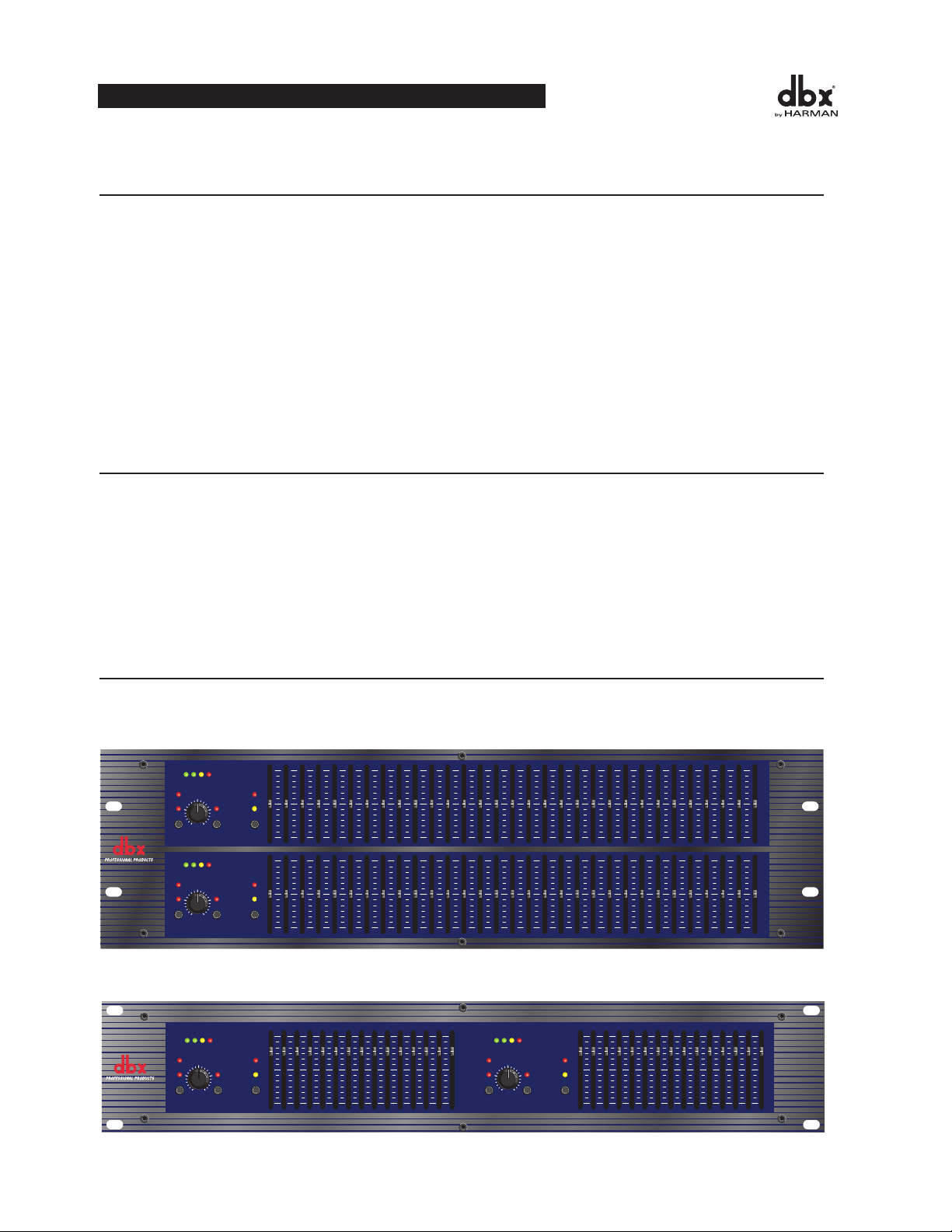
IntroduCCIón
Felicidadesporsucompradeunecualizadorgráficodbx.Todoslosecualizadoresgráficosdbxsonunidadesmulti-
funcionales de alto rendimiento diseñadas para poner en manos de los profesionales toda la flexibilidad y potencial
queestosrequieren.Lerecomendamosquedediqueunmomentoaleerporcompletoestemanualdeinstrucciones.
Enélpodráencontrarinformaciónqueleayudaráentodoslospasosdesdelaconfiguracióndesusistemahastalas
aplicacionesdelEQ.LosecualizadoresdelaSerie12incluyenlascaracterísticassiguientes:
•Rangodecorte/realceintercambiableentre±6dBy±15dB
•Entradasysalidasbalanceadas
•ConectoresXLR,TRSde6,3mmyregletadebornes
•Rangodegananciadeentrada-12dB/+12dB
•FiltrodecortedegravesdetipoBesselde40Hzy18dB/octava
•Posibilidaddedesconexióndetomadetierradechasis/señal
•Transformadordefuentedealimentacióninterno
•Bypassdedesconexiónporreléconretardodedossegundosenelencendido
InspeCCIón
Compruebequedentrodelacajadelecualizadorseencuentranlosartículossiguientes:
•Unecualizadorcuyonúmerodeseriecoincidaconelmarcadoenelembalaje
•UncabledealimentacióndeCA
•Manualdeinstrucciones
•Tarjetaderegistro
•Cuatrotornillosyarandelasparaelmontajeenrack
Sifaltasecualquieradeestosartículos,póngaseencontactoconelserviciodeatenciónalusuariodedbxeneltelé-
fono que viene indicado en la contraportada de este manual.
Controles operatIvos
Paneles Frontales
1231-ecualizadorgráficodecanaldualde31bandas
1215-ecualizadorgráficodecanaldualde15bandas
32
MANUAL DE INSTRUCCIONES
1231
Graphic Equalizer
20 25 31.5 40 50 63 80 500400315250 1.6k1.25k1k800 5k4k3.15k2.5k 16k12.5k10k8k6.3k 20k2k630100 125 160 200
RANGE
OUTPUT
LEVEL (dBu)
LOW
CUT
EQ
BYPASS
INPUT
GAIN
dB
-12
0
+12
+/-6
+/-15
CLIP
+18+100-10
RANGE
OUTPUT
LEVEL (dBu)
LOW
CUT
EQ
BYPASS
INPUT
GAIN
dB
-12
0
+12
+/-6
+/-15
CLIP
+18+100-10
0
-15
+15
0
-15
+15
0
-6
+6
0
-6
+6
85-XXXX-X 1231 FRONT ART 7-12-99
RANGE
OUTPUT
LEVEL (dBu)
LOW
CUT
EQ
BYPASS
INPUT
GAIN
dB
-12
0
+12
+/-6
+/-15
CLIP
0
-6
+6
25 40 63 100 160 250 400 16k10k6.3k4k630 1k 1.6k 2.5k
+18+100-10
1215
Graphic Equalizer
85-XXXX-A0 1215 FRONT ART 7-15-99
0
-15
+15
RANGE
OUTPUT
LEVEL (dBu)
LOW
CUT
EQ
BYPASS
INPUT
GAIN
dB
-12
0
+12
+/-6
+/-15
CLIP
0
-6
+6
25 40 63 100 160 250 400 16k10k6.3k4k630 1k 1.6k 2.5k
+18+100-10
0
-15
+15

Control Input Gain: Estecontrolajustaelniveldeseñalquevaalecualizador.Sucapacidadesde-12dBa+12dBde
ganancia.SuefectoesaparenteconsolomirarelGRAFICODEBARRASDENIVELDESALIDA.
EQ Bypass: Esteinterruptoreliminalaseccióndelecualizadorgráficodelarutadelaseñal.(Veaeldiagramadebloquesde
lapágina8).ElinterruptorBYPASS,sinembargo,noafectaalaGANANCIADEENTRADA,nialosfiltrosdeCORTE
DEGRAVES.
Piloto EQ Bypass:EsteLEDrojoseiluminacuandoelEQestéenelmodobypass.Tengaencuentaqueestemododeanu-
laciónsoloafectaalaseccióndeecualizadordelosEQsdelaSerie12.LoscontrolesINPUTGAINyLOWCUTnoseven
afectados cuando el ecualizador queda en bypass.
Interruptor y LEDs de selección de rango de realce/corte: Esteinterruptoreligecualdelosdosrangosderealce/corte
usaráelecualizador,sielde±6dBo±15dB.Elpilotorojoseiluminacuandoseseleccionaelrango±15dB,yelamarillose
enciendecuandoseeligeelrango±6dB.ObservequeelinterruptorBOOST/CUTestáligeramentehundido.Estoseha
hechoparaevitarlaactivacióndelinterruptorporaccidente,loquepodríaproducirposiblementedañosenelrestodelos
componentes de su sistema.
EstoscuatroLEDsindicanelniveldesalidadelecualizador.Elpilotorojoestá3dB
pordebajodelasaturaciónyestámarcadocomo+18dBu.Esteindicadorgráficoseocupademonitorizarelnivelenlasalida
delecualizadordespuésdelrestodeprocesados.
LED Clip: Estepilotoseiluminasiemprequeelniveldeseñalinternollegaalos3dBpordebajodelasaturación,loque
puedeocurrirencualquieradeestoscasos:1)cuandolaseñaldeentradaes“másactiva”que+22dBu,2)cuandoseaplica
demasiadagananciaconelcontroldegananciadeentrada,o3)cuandoseaplicaunrealceexcesivopormediodelosmandos
deslizantes de frecuencia.
Cadaunodeestospotenciómetrosdeslizantesrealzaránocortaránlafre-
cuenciacorrespondienteen±6dBo±15dB,dependiendodelaposicióndelinterruptorBOOST/CUTRANGE.Cuandotodos
estoscontrolesesténenlaposiciónconmuescacentrallasalidadelecualizadorseráplana.Loscentrosdelasbandasdefre-
cuenciadel1231estánmarcadosaintervalosde1/3deoctavaenseparacionesstandardISO,mientrasqueloscentrosdelas
bandasdefrecuenciadel1215estánmarcadosaintervalosde2/3deoctavaaseparacionesstandardISO.
Interruptor de activación de corte de graves: ElinterruptorLOW-CUTintroduceosuprimedelarutadelaseñalelfiltro
Besseldecortedegravesde40Hzy18dB/octava.CuandoesteinterruptorLOW-CUTestápulsado,elfiltrodeCORTEDE
GRAVESestáACTIVADOenlarutaaudio.
ConexIón del eQ a su sIsteMa
LosecualizadoresdelaSerie12tienenentradasysalidasbalanceadasquepuedenserusadasconcualquierunidadtantobal-
anceadacomonobalanceadaconniveldelínea.Paratenerunainformaciónmásespecíficaacercadelasposibilidadesde
cableado,vayaalaseccióntitulada.
Paraconectarelecualizadorasusistemadesonidosigalospasosquedetallamosacontinuación:
InstaleelEQenunrackpormediodelostornillosdemontajeenrackincluidos.Puedecolocarlotantoencimacomo
debajodecualquierunidadquenogenereuncalorexcesivo.Latemperaturadeambientenodeberíasobrepasarlos45°C
cuandoseutilizaseelaparato.Aunquelacarcasadelaunidadestáprotegidacontralasinterferenciaselectromagnéticas
ydefrecuenciasderadio,debeevitarloscamposdeRFoEMIextremadamentealtos.
Puedeusarlostrestiposdeconectoresparalasentradasylassalidasparaconex-
ionestantobalanceadascomonobalanceadas.Elusodemásdeunconectorsimultáneoparalasentradaspuededesbal-
ancearlaslíneasbalanceadas,produciendocancelacionesdefase,elcortedeunconductoramasa,oproduciendodaños
aotrosaparatosqueesténconectadosalecualizador.Puedeutilizarsimultáneamentemásdeunasalidasiemprequela
carga en paralelo combinada sea mayor de
600Ω.
Nota: Asegúrese de reducir los niveles audio en las etapas de potencia cuando modifique el ajuste de este interruptor ya que puede generar un
transitorio audible.
ConecteelcablederedCAalreceptáculodecorrienteCAdelaparteposteriordelecualizador.Introduzcael
enchufedelotroextremodeesecableenunasalidadecorrientequeestéseparadadelaslíneasaudio.Elapara-
to puede ser conectado y desconectado con el interruptor de encendido del panel posterior o con un interruptor
deencendidodeunsistemadecontrol.DadoquelosecualizadoresdelaSerie12consumenunacantidadde
MANUAL DE INSTRUCCIONES
33
ECUALIZADORES GRAFICOS SERIE 12
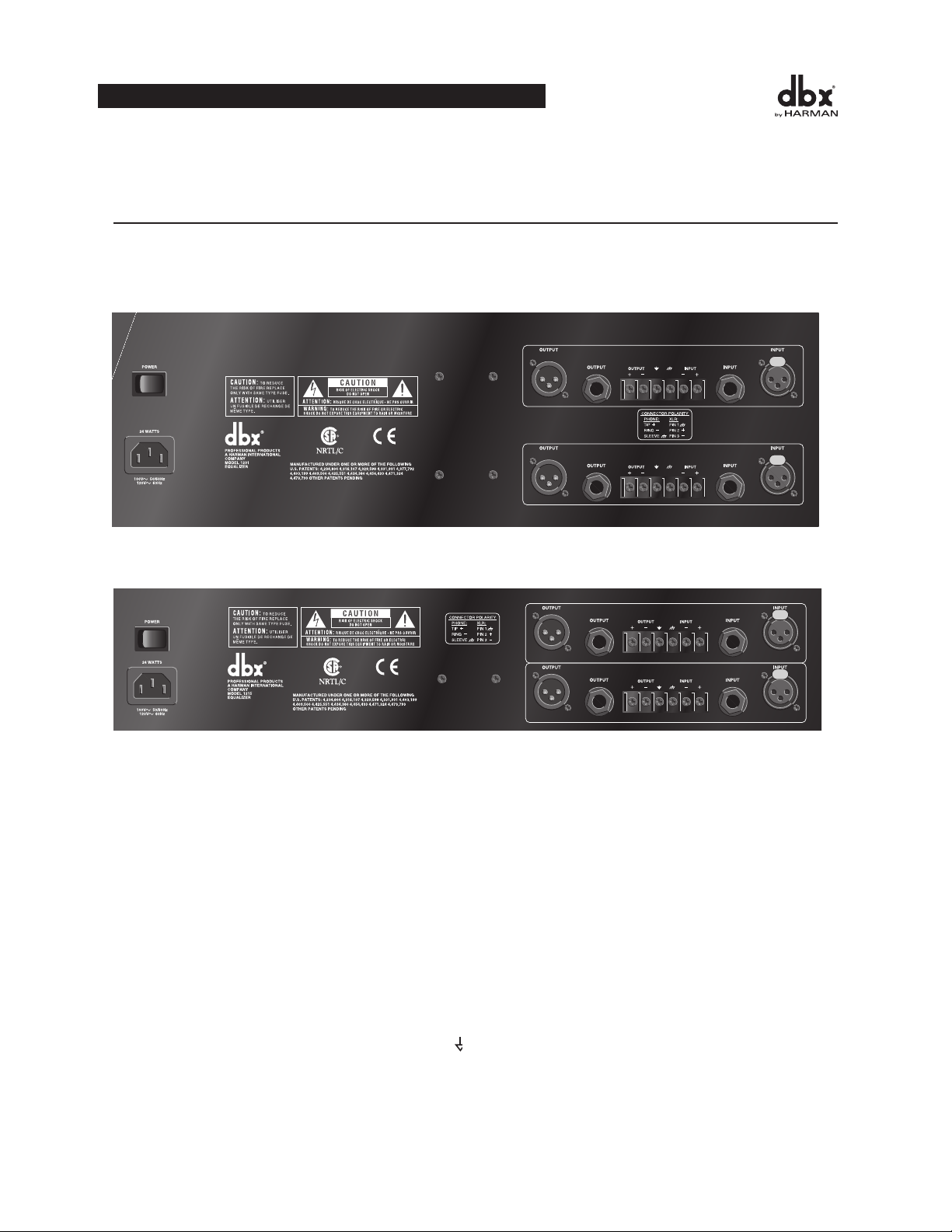
potenciarelativamentebaja,puededejarlasunidadesencendidasdeformacontinuada.
desCrIpCIones del panel posterIor
Paneles Posteriores
1231-ecualizadorgráficodecanaldualde31bandas
1215-ecualizadorgráficodecanaldualde15bandas
Interruptor Power: Enciendeyapagalaunidad.Realicesiempretodaslasconexionesaudioconesteinterruptor
colocadoenlaposiciónOFF.
Receptáculo de cable de corriente:Conexióndeentradadelacorrientealternaalecualizador.
Conectores de salida:Disponedetrestiposdeconectoresdesalidaparalasconexionesdesalida:conectoresde
tipoXLRmacho,conectoresdetipoauricularesdepunta-anillo-lateralde6,3mmyunaregletadebornes.
Conectores de entrada: Disponedetrestiposdeconectoresdeentradaparalasconexionesdeentrada:conectores
detipoXLRhembraconpestañadeseguridad,conectoresdetipoauricularesdepunta-anillo-lateralde6,3mmy
unaregletadeconexionesdetipoborne.Elniveldeentradamáximaquepuedeaceptarelecualizadoresde
+22dBu(ref:0.775Vrms).
Alquitarelpuentequeconectalosdostornillosdelaregletadebornes,
la toma de tierra del chasis se separa del circuito de toma de tierra del ecualizador. Esto es necesario a veces para
evitarlos“buclesatierra”enunsistemadesonido.Cuandoquitelabandadetomaatierra,deberárealizarunacon-
exióndesdelaterminaldetomadetierradelcircuito(
++
+
++
+
++
Without Jumper in Place With Jumper in Place
jumper
optional
circuit
ground
chassis
ground
circuit
ground
chassis
ground
to system
ground
optional
WIRING CONNECTIONS WITH GROUND
Input
Cable
Output
Cable
Input
Cable
Output
Cable
)aalgúnotropuntodetomadetierradesusistemadesoni-
do para que el ecualizador pueda funcionar de forma correcta.
34
MANUAL DE INSTRUCCIONES

Conexiones de cable con toma de tierra
ConsIderaCIones para la InstalaCIón
LosecualizadoresdelaSerie12hansidodiseñadosparanivelesnominalesde
+4dBu.Losecualizadorespuedenserusadosconfuentestantobalanceadascomonobalanceadas,ylassalidas
puedenserusadasconcargastantobalanceadascomonobalanceadas,asumiendoqueutiliceloscablesadecuados.
Unalíneabalanceadasedefinecomouncablededosconductoresymallaenelquelosdosconductorescentrales
llevanlamismaseñalperoconunapolaridadopuestaenrelaciónatierra.Unalíneabalanceadaesgeneralmenteun
cableblindadoconunúnicoconductorquellevalaseñalmientrasquelamallaoblindajeestáapotencialdetierra.
Elecualizadortieneunaimpedanciadeentradade40kΩ balanceados y
20kΩ no balanceado. Esto hace que las entradas audio de los ecualizadores de la Serie 12 sean adecuadas para ser
usadasprácticamenteconcualquierfuentedebajaimpedancia(pordebajode2kΩ).
Lasalidadelecualizadorescapazdecontrolarunacargade600Ω hasta los
+18dBu.Paraconseguirelmáximorechazoaloszumbidosconunafuentebalanceada,evitelastomasdetierra
comunesenlasentradasysalidasdelecualizador.Lamayoríadecablesbalanceados(3conductores)tienenlamalla
conectadaenambosextremos.Estopuedeproducirbuclesdetomadetierraqueproduciránzumbidos.Sielzumbi-
dopersiste,pruebeadesconectarlamallaenunoomásdeloscablesdelsistema,preferiblementeenlaentradade
unaunidad,noenlasalida.
notas aCerCa del FunCIonaMIento y las aplICaCIones
LosecualizadoresgráficosdbxdelaSerie12sonherramientasdeprocesadodelaseñalaudiorealmenteútilespara
situaciones en las que sea necesario un control preciso de la frecuencia en todo el espectro de frecuencias audibles.
Cuandoseusanconunanalizadordeespectroaudio,losEQspuedenajustarcualquierentornoacústico--desdeel
estudioalasaladeconciertos--paradetenerlosrepiques,aumentarlaclaridadyaplanarlarespuestadefrecuencia
globaldelentorno.Unanalizadordeespectrodetiemporealuotrostiposdeanalizadoresdeentornosaudioson
muyútilesparaladeterminacióndelacantidaddeecualizaciónnecesaria.
Inserteelecualizadorgráficoentrelafuentedeseñal(habitualmenteunamesademezclas)ylasetapasdepotencia
(oelcrossoversiesquehayalguno).Ajusteelnivelylaecualizaciónenlaformanecesariaparaconseguirlarespu-
estadelsistemaquedesee.LosfadersomandosdeslizantesdelargorecorridodelosEQspermitenrealizarajustes
precisosdelaecualizacióndecaraaconseguircurvasdeecualizaciónexactas.
Paraconseguirlamejorrespuestaseñal-ruido,deberáajustarcorrectamentelaestructuradegananciadelsistemade
sonido.Cadaunodeloscomponentesdelsistemadeberíaserajustadoasuniveloperativonominal,comenzando
conelprimerelementodelsistema,habitualmenteunamesademezclas.Cadaelementodeberíafuncionarasu
niveloperativonominalparasacarpartidodelasmáximaspropiedadesderelaciónseñal-ruidodedichoelemento.
Lasetapasdepotencia,comoúltimoelementodelacadena,deberíanserajustadassolotanaltocomoseanecesario,
decaraaevitarlainduccióninnecesariaderuidoenelsistema.
MANUAL DE INSTRUCCIONES
35
ECUALIZADORES GRAFICOS SERIE 12
++
+
++
+
++
Without Jumper in Place With Jumper in Place
jumper
optional
circuit
ground
chassis
ground
circuit
ground
chassis
ground
to system
ground
optional
WIRING CONNECTIONS WITH GROUND
Input
Cable
Output
Cable
Input
Cable
Output
Cable

sopòrte téCnICo / reparaCIones en FáBrICa
Todos los EQs dbx de la Serie 12 son aparatos robustos que disponen de unos componentes escogidos por su alto
rendimiento y excelente fiabilidad. Cada una de las unidades ha sido comprobada y verificada en cuanto a su func-
ionamientoenfábrica.Noesnecesariorealizarningúntipodeajustealolargodetodalavidadeesteaparato.
Sienalgúnmomentoesteaparatodebeserreparado,lerecomendamosqueenvíesuEQafábrica.Parahaceresto,
primerodeberáconseguirunnúmerodeAUTORIZACIONDEDEVOLUCIONqueleseráfacilitadoporeldepar-
tamentodeatenciónalclientededbx.
Sinecesitacualquiertipodesoportetécnico,contacteconeldepartamentodeatenciónalcliente.Tengaamano
todolonecesarioparadescribirelproblemaconprecisión.Deberáindicarnoselnúmerodeseriedelaunidad(está
impresoenunaetiquetapegadaalchasisdelaunidad).
Lainformacióndecontactoestáenlacontraportadadeestemanual.
36
MANUAL DE INSTRUCCIONES

speCIFICatIons / CaraCtérIstIQues teChnIQues /
t
eChnIsChe daten / espeCIFICaCIones
Connectors: 1/4"TRS,femaleXLR(pin2hot),andbarrierterminalstrip
Connecteurs: Jacks6,35mm,XLRfemelle(pointchaud=broche2)etbornier
Anschlüsse: 6,3-mm-Stereoklinkenbuchsen,XLR-Buchsenweibl.(Inphase=Stift2)und
Klemmleiste
Conectores: Clavijasjackestéreo6,3mm,XLRhembra(espiga2=enfase)yregletadebornes
Type: Electronicallybalanced/unbalanced,RFfiltered
Type: Symétrie,asymétrieélectroniques,filtréescontrelesinterférencesradio
Schaltung: Elektronischsymmetriert/asymmetrisch,HF-geschützt
Tipo: Electrónicamentebalanceado/desbalanceado,confiltroRF
Impedance: Balanced40kΩ,unbalanced20kΩ
MaxInputLevel: >+21dBubalancedorunbalanced
CMRR: >40dB,typically>55dBat1kHz
Connectors: 1/4"TRS,maleXLR(pin2hot),andbarrierterminalstrip
Connecteurs: Jacks6,35mm,XLRfemelle(pointchaud=broche2)etbornier
Anschlüsse: 6,3-mm-Stereoklinkenbuchsen,XLR-Buchsenmännl.(Inphase=Stift2)und
Klemmleiste
Conectores: Clavijasjackestéreo6,3mm,XLRmacho(espiga2=enfase)yregletadebornes
Type: Impedance-balanced/unbalanced,RFfiltered
Type: Symétrique,asymétrique
Schaltung: Impedanzsymmetriert/asymmetrisch,HF-geschützt
Tipo: Balanceadoporimpedancia/desbalanceado,confiltroRF
Impedance: Balanced200Ω,unbalanced100Ω
MaxOutputLevel: >+21dBubalanced/unbalancedinto2kΩ or greater
>+18dBmbalanced/unbalanced(into600Ω)
Bandwidth: 20Hzto20kHz,+0.5/-1dB
FrequencyResponse: <10Hzto>50kHz,+0.5/-3dB
+/-15dbRange +/-6dbRange
DynamicRange: 109db 115db
Signal-to-Noise: 90db 97db
THD+Noise: <0.005%
InterchannelCrosstalk: <-80dB,20Hzto20kHz
EQ BYPASS: Bypassesthegraphicequalizersectioninthesignalpath
“Bypasse”lasectioncorrecteurgraphique
Schaltet den graphischen Equalizerteil aus dem Signalweg aus
Haceunaderivacióndelaseccióndeecualizadorgráficoenelcaminodelaseñal
(recessed): Activatesthe40Hz18dB/octaveBesselhigh-passfilter
(enfoncé): Activelefiltrepasse-haut40Hz18dB/octavedetypeBessel
(versenkt): SchaltetdasBessel-Hochpassfilter(40Hz,18dB/Oktave)einundaus
(empotrado): ActivaelfiltrodepasoaltodeBesselde40Hz,18dB/octava
(recessed): Selectseither+/-6dBor+/-15dBsliderboost/cutrange
(enfoncé): Sélectionnelaplaged’atténuation/accentuation+/-6dBou+/-15dB
(versenkt): SchaltetdenRegelbereichderSchiebereglerzwischen+/-6dBund+/-15dBum.
(empotrado): Seleccionaunadelasdosgamasrefuerzo/cortedelosdeslizadores:+/-6dBó+/-15dB
: 4-LEDbargraph(Green,Green,Yellow,Red)at-10,0,+10,and+18dBu
VUmètre4-Leds(verte,verte,jaune,rouge)à-10,0,+10,et+18dBu
4-teiligeLED-Zeile(grün-grün-gelb-rot)bei-10,0.+10,+18dBu
4LEDs(verde,verde,amarillo,rojo)a-10,0,+10y+18dBu
EQ BYPASS: 1LED:red/rouge/rot/rojo
CLIP: 1LED:red/rouge/rot/rojo
: 1LED:red/rouge/rot/rojo
1LED:yellow/jaune/gelb/amarillo
: 1LED:red/rouge/rot/rojo
OPERATION MANUAL
37
12 SERIES GRAPHIC EQUALIZERS

OperatingVoltage: 100VAC50/60Hz,120VAC60Hz,230VAC50/60Hz
Tension:
Netzspannung:
Tensiónderegimen:
PowerConsumption: 121524W;123124W
Consommation:
Leistungsaufnahme:
Consumodeenergía:
MainsConnection: IECreceptacle
Connecteursecteur: PrisechâssisIEC
Netzanschluss: IEC-Kaltgerätebuchse
Conexióndered: tomacorrienteIEC
Dimensions: 1215:3.5"HX19"WX7.9"D(8.9cmx48.3cmx20.1cm)
1231:5.25"HX19"WX7.9"D(13.4cmx48.3cmx20.1cm)
Dimensions(hxlxp): 1215:89x483x201mm
Abmessungen(HxBxT):1231:134x483x201mm
Dimensiones(alxanxprf:
Weight: 1215:8.5lbs.
1231:10.6lbs.
Poids: 1215:3.9kg
Nettogewicht: 1231:4.8kg
Pesoneto:
ShippingWeight: 1215:9.5lbs.
1231:11.6lbs.
Poidsàl’expédition: 1215:4,3kg
Bruttogewicht: 1231:5,3kg
Pesodeembarque:
Note:Specificationssubjecttochange.
Note:Caractéristiquessujettesàmodifications.
Anm.: Technische Änderungen vorbehalten.
Nota:Especificacionessujetasacambio.
38
OPERATION MANUAL
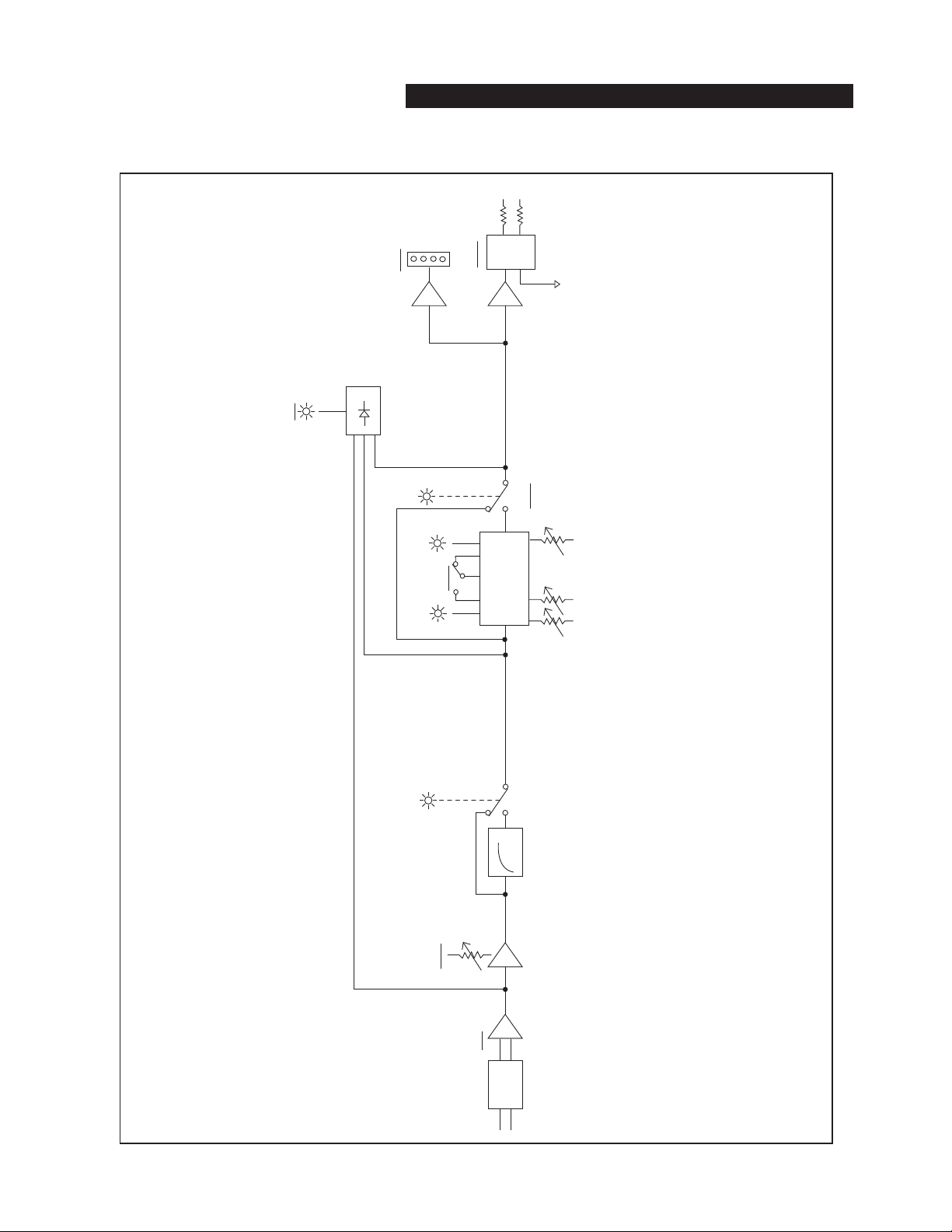
OPERATION MANUAL
39
12 SERIES GRAPHIC EQUALIZERS
.....
40Hz
GRAPHIC
EQ
20Hz
20kHz
EQ
Bypass
±6dB ±15dB
Range
CLIP
Input
Gain
Input
Output
Level
RF Filter
RF
Filter
Output
dbx 1231 Graphic Equalizer
Block Diagram

8760 South Sandy Parkway • Sandy, Utah 84070
Phone: (801) 568-7660 • Fax (801) 568-7662
Int’l Fax: (801) 568-7583
Questions or comments?
Contact us at www.dbxpro.com
Part No: 18-6340V-B - Printed in China