Loading ...
Loading ...
Loading ...
9 ■English
Wiring
WARNING
• Donotusetappedwires,extensioncords,orstarburstconnections,astheymaycauseoverheating,electricshock,orre.
• Do not use locally purchased electrical parts inside the product. (Do not branch the power for the drain pump, etc., from the
terminalblock.)Doingsomaycauseelectricshockorre.
• The circuit must be protected with safety devices in accordance with local and national codes, i.e. a circuit breaker.
• Use an all-pole disconnection type circuit breaker with at least 1/8 inch (3mm) between the contact point gaps.
• When carrying out wiring, take care not to pull at the conduit.
• Donotconnectthepowerwiretotheindoorunit.Doingsomaycauseelectricshockorre.
• Do not turn on the circuit breaker until all work is completed.
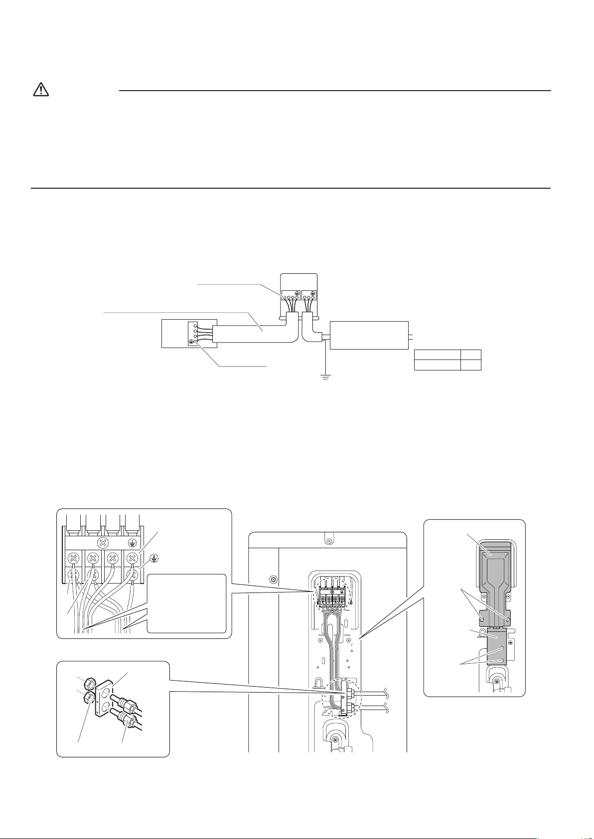
1) Strip the insulation from the wire (3/4 inch (20mm)).
2) Connect the inter-unit wires between the indoor and outdoor units so that the terminal numbers match. Tighten the
terminal screws securely. It is recommended that a slot-head screwdriver be used to tighten the screws.
The screws are packed with the terminal block.
1
2
3
1 2 3
Follow local codes for wiring
and safety devices between
outdoor unit and power
source.
Ground
Firmly fix the wires with
the terminal screws.
Recommend using AWG14, stranded and insulated
wire for connections between indoor and outdoor units.
Local code always supersedes recommendation.
Outdoor unit
Indoor
unit
Power supply
60Hz 208-230V
Firmly fix the
wires with the
terminal screws.
L
1
L
2
Note: Take care to ensure that all wiring between
indoor unit and outdoor unit has a consistent
connection. Any splices can cause communication
errors.
RX09/12/15/18∗
20A
15A
RX24∗
09/12 class
[Method of mounting conduit]
• Aprotectionplateisxedforprotectionfromthehigh-voltagesection.
1) Dismount the stop valve cover by removing the screw.
2) Dismount the protection plate by removing the 2 screws.
3) Dismount the conduit mounting cover by removing the 2 screws.
4) Pass wires through the conduit and secure them with a lock nut.
5) After completing the work, reattach the stop valve cover, the conduit mounting cover, and the protection plate to its
original position.
1
2
3
1
2
3
1
2
3
Screws
Conduit
mounting
cover
Screws
Protection plate
Power supply
terminal block
Shape wires so
that the protection
plate and conduit
mounting plate fit
securely.
Conduit
Lock nut
Conduit
mounting
plate
L
1
L
2
01_EN_3P500432-2B.indd 9 10/30/2018 11:53:03 AM
Loading ...
Loading ...
Loading ...