Loading ...
Loading ...
Powered Liners Installation Detail:
MODELS: MODELS: MODELS:
C2000SD2 C2000SD4 C2000BP1
C2000BP C2000BP1-TW C2000PS
C2000PS1-TW C2000PSB (Baffle Filters)* C2000PS1-TWB (Baffle Filters)*
C2000BPB (Baffle Filters)* C2000BP1B (Baffle Filters)* C2000BP1-TWB (Baffle Filters)*
C200SD4-12 NEW** C2000PS-IS22, IS28
Island Style C2000PS1-TW-IS22, IS28 Island Style
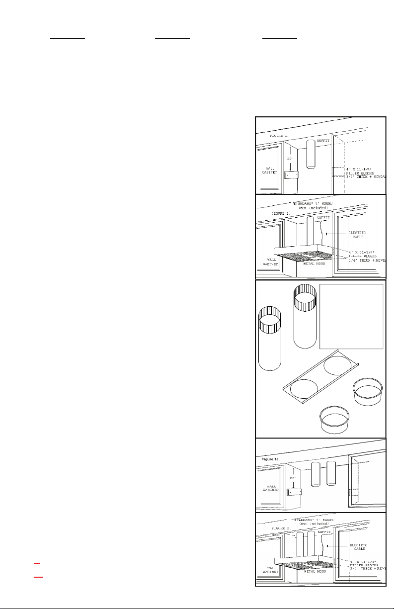
1. Scribe line below top of cabinet to meet with bottom of
hood. Repeat on the opposite cabinet. (Figure 1)
2. Position 4” x 11 1/4” x 3/4” wood block flat on side of
cabinet with end of filler block against wall and secure
with screws. Remove Filters.
3. Raise and position Power Liner so that bottom is level with
scribed lines on cabinets and drive screws through holes in
the ends of the Powered Liner. (Figure 2)
Use our exclusive positioning kit if needed. The duct pipe
or pipes should slip into the Automatic Seal Vent Collar.
Be sure to remove the black tape that holds the Damper
blades closed.
4. If required additional mounting at the Rear of unit:
Locate wall studs, drill holes through back of Powered
Liner to hit studs and attach the Liner to the wall
with screws.
5. Island and Peninsula Powered Liners should be
mounted in the same way except there will be no rear
wall mount.
6. Bring conduit down 4” past the bottom of the liner.
Note: Top box for the C2000BP1 shows vent opening
Off set to the left (facing the hood). The lower box is
the same size as in the drawing to the right.
7. Remove junction box cover from the C2000.
(Be sure to comply with all local electrical and safety codes).
8. Hook up electrical wires and secure reattach junction box.
9. Replace junction box cover. Install lights and replace
filters. For Baffle Filters, install grease tray towards the back
of liner. Take one baffle, slide between steel strips towards the
front of the liner and push back into grease tray grooves, then
slide to one side. Insert second baffle the same way and slide
to opposite side. (Grease holes, on bottom of baffle must be
inserted into grease tray) Take Center Panel and slide in
towards the front of the liner and push back into grease tray.
10. TWIN UNITS ONLY - Transitioning two pipes into one
is NOT recommended. CFMs are reduced by 25% and the
Performance warranty will be void.
*Baffle Units Only - top box dimension is 6” high.
Duct Sizes Indicated in Model # (Ex: C2036PS-8-SS)
** - 8 = 8” DUCT PIPE
** - K=10” DUCT PIPE
*Positioning
Kit consists
of two lower
pieces, not the
duct pipe.
*Only available on two
7” Round Ducts.
Loading ...
Loading ...
Loading ...