Loading ...
Loading ...
Loading ...
10
7HFKQLFDO,QIRUPDWLRQ
Service Manual
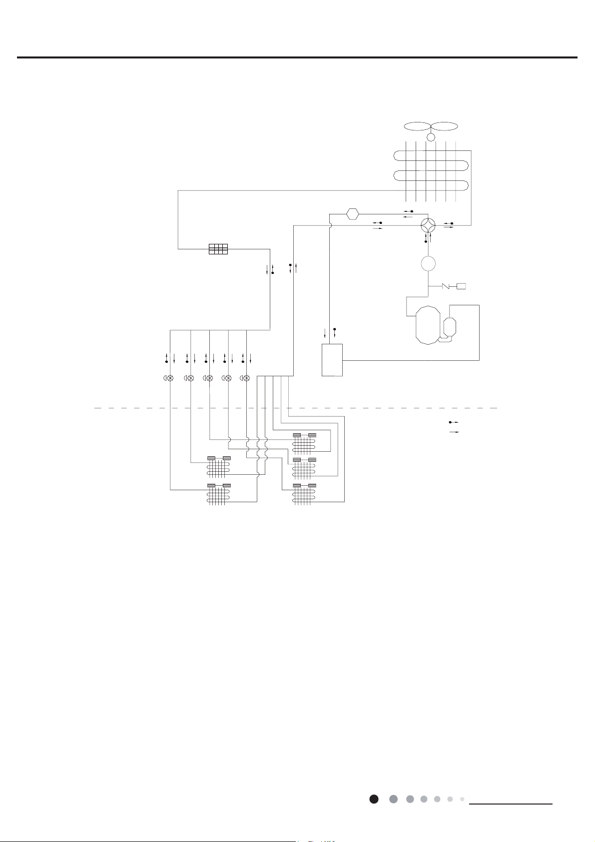
4. Refrigerant System Diagram
Schematic Diagram of Free Match Series Inverter Heat Pump System
M
Heat Exchanger
Four-way Valve
Compressor
Silencer
Gas/Liquid Separator
Heat Exchanger
Heat Exchanger
Heat Exchanger
Heat Exchanger
Heat Exchanger
Heating
Cooling
Outdoor Uint
Indoor Uint
Electronic Expansion Valve
Schematic Diagram of Free Match Series Inverter Heat Pump System
The outdoor and indoor units start to work once the power is switched on. During the cooling operation,
the low temperature, low pressure refrigerant gas from the heat exchanger of each indoor unit gets together
and then is taken into the compressor to be compressed into high temperature, high pressure gas, which will
soon go to the heat exchanger of the outdoor unit to exchange heat with the outdoor air and then is turned into
refrigerant liquid. After passing through the throttling device, the temperature and pressure of the refrigerant
liquid will further decrease and then go the main valve. After that, it will be divided and go to the heat exchanger
of each indoor unit to exchange heat with the air which needs to be conditioned. Consequently, the refrigerant
liquid become low temperature, low pressure refrigerant gas again. Such a refrigeration cycle goes round and
round to achieve the desired refrigeration purpose. During the heating operation, the four-way valve is involved
to make the refrigeration cycle run reversely. The refrigerant radiates heat in the heat exchanger of the indoor
unit (so do the electric heating devices) and absorb heat in the heat exchanger of the outdoor unit for a heat
pump heating cycle so as to achieve the desired heating purpose.
High Pressure Swicth
Filter
Eutectic Stopper
Loading ...
Loading ...
Loading ...