iNSTALLATiON AND SERVICEMUST BE PERFORMED BY A QUALiFiED iNSTALLER.
iMPORTANT: SAVE FOR LOCAL ELECTRICAL iNSPECTOR'S USE.
READ AND SAVE THESE iNSTRUCTiONS FOR FUTURE REFERENCE.
If the information in this manual is not followed exactly, a fire or
explosion may result causing property damage, personal injury or death.
FOR YOUR SAFETY:
-- Do not store or use gasoline or other flammable vapors and liquids in the
vicinity of this or any other appliance.
-- WHATTO DO IFYOU SMELLGAS:
• Do not try to light any appliance.
• Do not touch any electrical switch; do not use any phone in your building.
• Immediately call your gas supplier from a neighbor's phone. Follow the
gas supplier's instructions.
• If you cannot reach your gas supplier, call the fire department.
-- Installation and service must be performed by a qualified installer,
service agency or the gas supplier.
Appliances Installed in the
state of Massachusetts:
This Appliance can only be
installed in the state of
Massachusetts by a
Massachusetts licensed plumber
or gasfitter.
This appliance must be installed
with a three (3) foot / 36 in. long
flexible gas connector.
A"T" handle type manual gas
valve must be installed in the gas
supply line to this appliance.
For existing 29" (73.7 cm) cutout
width opening, you must call the
Service Center for optional thinner
side panels. Also you must prepare
the countertop edge as shown in the
"Countertop Preparation" section
(see page 5).
I Y2" Max.
Shave Raised (3.8 cm Max.
Edge to Clear
Space for a
31s/_e,,min
(81 cm)
Wide
Cooktop.
DimensionC in
table.
These surfaces should
be flat & leveled
(hatched area
1/2" Min._
5" Min
30" Min.
76.2 cm Min.
18" Min.
(45.7 cm) Min.
\13"
(33 cm)
IMPORTANT:
Cabinet and
countertop
width should
match the
cutout width.
Locate Cabinet Doors
1" (2.5 cm) Min. from
Cutout Opening.
E
E
24" Min.
(61 cm Min.)
Grounded Jorlction Box or Wall Outlet
Should BeLocated 8" to 17" (20.3 cm to
43.2 cm) From Right Cabinet and 2" to
4" (5.1 cm to 10.2 cm) From Floor.
Do not install the unit in the cabinet before reading next two pages.
A. HEIGHT B. WIDTH' C, COOKTOP DIDEPTHTO E. CUTOUTWIDTH*** F. CUTOUT G. HEIGHT
30" (76,2 cm) Porcelain
31 5/16" (79.5 cm)
Glass
3I 1/2" (8I cm)
28 5/I6" (71,9 cm)
30±1/16"
(76,2±0,I 5 cm}
35 518" (90.5 cm} -
36 518" (93 cm}
NOTE: Wiring diagram for these appliances are enclosed in this booklet.
Printed in United States
21 3/4" (55,2 cm} Min. 36 5/8" (93 cm) Max.
22 I/8" (56,2 cm) Max 35 5/8" (90.5cm} Min.
24" (61 cm) Min. with
backguard
P/N 318201674 (0604) Rev. D
English - pages 1-14
Espahol - paginas 15-28
Wiring Diagrams - pages 29-32
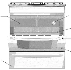
NOTES:
O Do not pinch the power supply cord between the range and the wall.
Do not seal the range to the side cabinets.
24" (61 cm) minimum clearance between the cooktop and the bottom of the cabinet when
the bottom of wood or metal cabinet is protected by not less than 1/4" (0.64 cm) flame
retardant millboard covered with not less than No. 28 MSG sheet metal, 0.015" (0.4 mm)
stainless steel, 0.024" (0.6 mm) aluminum, or 0.020" (0.5 mm) copper.
30" (76.2 cm) minimum clearance when the cabinet is unprotected.
For cutouts below 22 7/8"(58.1 cm), appliance will slightly show out of the cabinet.
Allow at least 19 ¼" (48.9 cm) clearance for door depth when it is open.
22 7/8" (58.1 cm) min.
23 1/4" (59.05 cm) max.
_!_-- (see Note 4) ---_
11/8"
(2.86 cm)
FRONT
OF _ F
CABINET Ref.
Door Open
(see note 5)
/
t j
21¾"
(55.25 crn)_'1
A
Side Panel
A. HEIGHT B. WIDTH
35 5/8" (90.5 cm)- 30" (76,2 cm)
36 5/8" (93 cm)
I
C. COOKTOP D. DEPTH TO
31 5116" 28 5/16" (71,9 cm)
(79.5 cm}
I
E. CUTOUT WIDTH *** F. CUTOUT G. HEIGHT
30±1/16" 21 3/4" (55,2 cm) Min. 365/8" (93 cm} Max.
(76,2±0,15 cm} 22 1/8" (56,2 cm) Max 35 5/8" (90.5 cm) Min.
24" (61 cm) Min. with
backguard
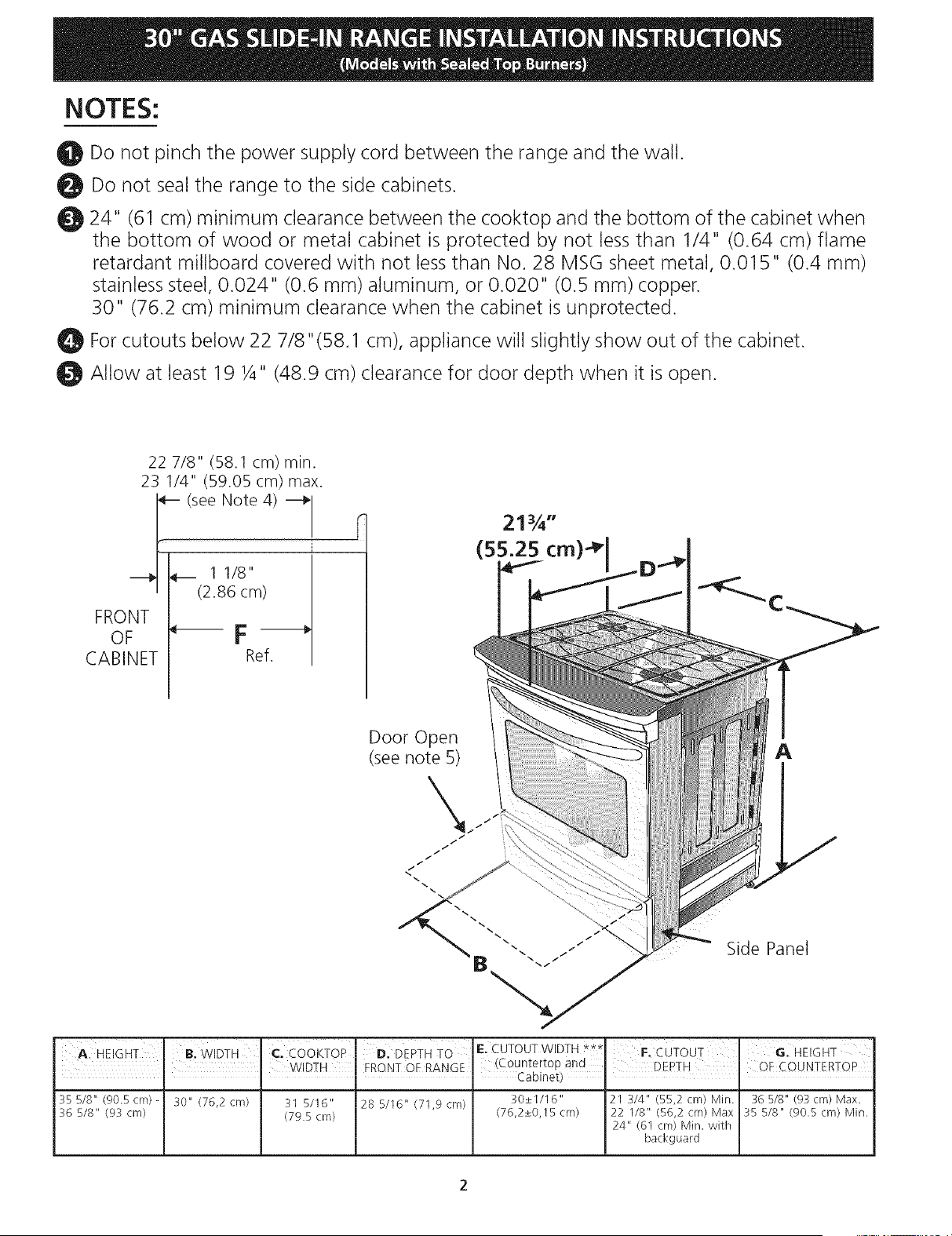
To avoid breakage: Do NOT handle or
manipulate the unit by the cooktop glass.
The counter-top around the cut-out should be flat and
leveled (see hatched area on illustration 1).
Before installing the unit, measure the heights of the two (2)
cabinet sides (H1-4), front and back (see illustration 1) from the
floor to the top of the counter.
Level the range using the
four (4)leveling legs so
that the height from the
floor to the underside of
the cooktop glass is
greater than the tallest
cabinet measurement by
at least 1/1 6" (see
Shave
Raised
Edge
to Clear
Space for,
31Y2" (81 cm) Wic
Cooktop.
illustration 2).
1 Y2"Max. 1
(3.8 cm Max.) I
Illustration 1
Slide the unit into the cabinet. Make sure the center of the unit is
aligned with the center of the cabinet cut-out.
Remove the protective channels on each side of the glass
cooktop (if provided).
The metal flange under each side of the cooktop MUST be
placed over the cabinet countertop for proper unit support.
The glass cooktop should NOT directly touch the countertop
(see illustration 2) or could cause glass breakage voiding the
warranty. Level the unit if needed.
After the installation, MAKE SURE that the
is supported by the leveling legs NOT by the
cooktop.
_.:
.To successfully install
the range, the initial
level height from floor
to underside of
cooktop glass should
be at least 1/16" taller
than cabinet sides as
measured in step 1.
Illustration 2
Important Notes to the Installer
1. Read all instructions contained in these installation
instructions before installing range.
2. Remove all packing material from the oven
compartments before connecting the gas and electrical
supply to the range.
3. Observe all governing codes and ordinances.
4. Be sure to leave these instructions with the consumer.
Important Note to the Consumer
Keep these instructions with your Use & Care Guide for
future reference.
• Do not obstruct the flow of combustion air at the
oven vent nor around the base or beneath the
lower front panel of the range. Avoid touching the
vent openings or nearby surfaces as they may become
hot while the oven is in operation. This range requires
fresh air for proper burner combustion.
Never leave children alone or
unattended in the area where an appliance is in use.
As children grow, teach them the proper, safe use of all
appliances. Never leave the oven door open when the
range is unattended.
IMPORTANT SAFETY
INSTRUCTIONS
Installation of this range must conform with local codes
or, in the absence of local codes, with the National Fuel
Gas Code ANSI Z223.1/NFPA .54-latest edition.
This range has been design certified by CSA
International. As with any appliance using gas and
generating heat, there are certain safety precautions you
should follow. You will find them in the Use and Care
Guide, read it carefully.
• Be sure your range is installed and grounded
properly by a qualified installer or service
technician.
• This range must be electrically grounded in
accordance with local codes or, in their absence,
with the National Electrical Code ANSI/NFPA No.
70--latest edition. SeeGrounding Instructions.
• Before installing the range in an area covered with
linoleum or any other synthetic floor covering,
make sure the floor covering can withstand heat at
least 90°F above room temperature without
shrinking, warping or discoloring. Do not install the
range over carpeting unless you place an insulating pad
or sheet of Y4" (10,16 cm) thick plywood between the
range and carpeting.
• Make sure the wall coverings around the range
can withstand the heat generated by the range.
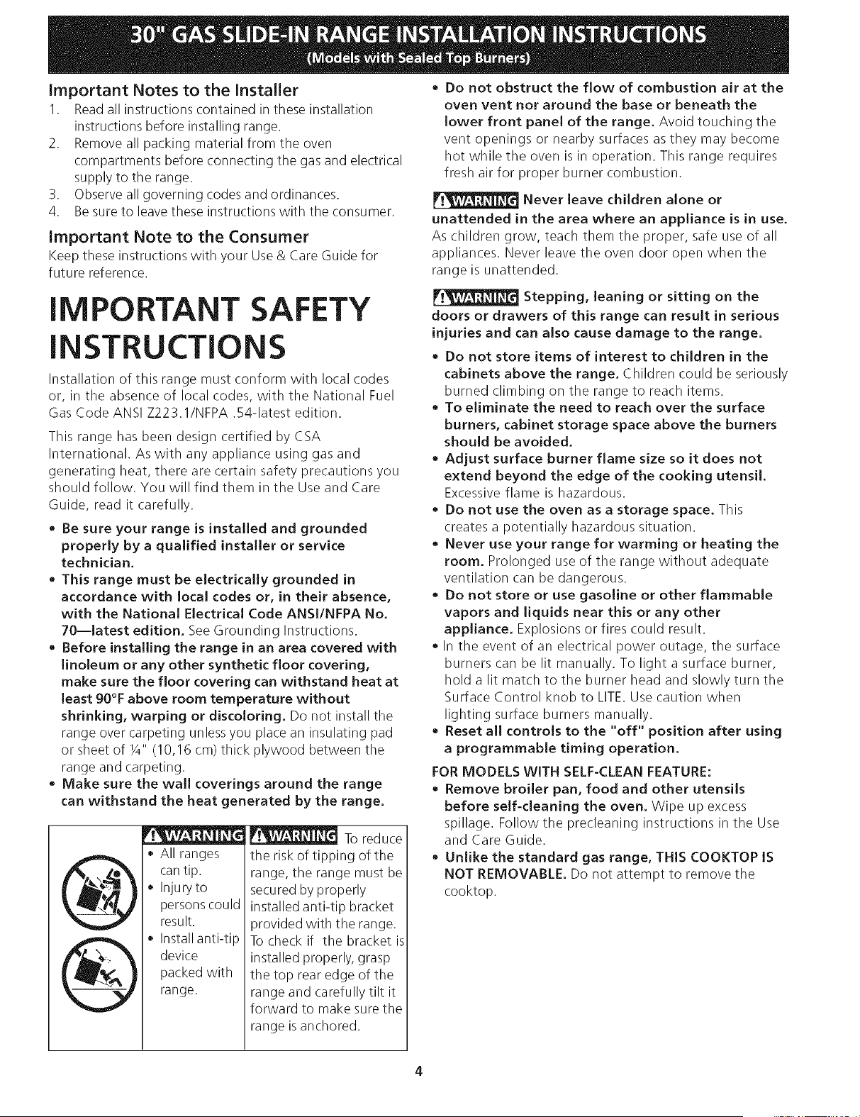
All ranges
can tip.
Injuryto
persons could
result.
Install anti-tip
device
packed with
range.
I_ To reduce
the risk of tipping of the
range, the range must be
secured by properly
installed anti-tip bracket
provided with the range.
To check if the bracket is
installed properly, grasp
the top rear edge of the
range and carefully tilt it
forward to make sure the
range is anchored.
Stepping, leaning or sitting on the
doors or drawers of this range can result in serious
injuries and can also cause damage to the range.
• Do not store items of interest to children in the
cabinets above the range. Children could be seriously
burned climbing on the range to reach items.
To eliminate the need to reach over the surface
burners, cabinet storage space above the burners
should be avoided.
• Adjust surface burner flame size so it does not
extend beyond the edge of the cooking utensil.
Excessive flame is hazardous.
• Do not use the oven as a storage space. This
creates a potentially hazardous situation.
• Never use your range for warming or heating the
room. Prolonged use of the range without adequate
ventilation can be dangerous.
Do not store or use gasoline or other flammable
vapors and liquids near this or any other
appliance. Explosions or fires could result.
In the event of an electrical power outage, the surface
burners can be lit manually. To light a surface burner,
hold a lit match to the burner head and slowly turn the
Surface Control knob to LITE. Use caution when
lighting surface burners manually.
• Reset all controls to the "off" position after using
a programmable timing operation.
FOR MODELS WITH SELF-CLEAN FEATURE:
• Remove broiler pan, food and other utensils
before self-cleaning the oven. Wipe up excess
spillage. Follow the precleaning instructions in the Use
and Care Guide.
• Unlike the standard gas range, THIS COOKTOP IS
NOT REMOVABLE. Do not attempt to remove the
cooktop.
©
©
Cabinet Construction
To eliminate the risk of cabinet
burns and fire, do not have cabinet storage space
above the range. If there is cabinet storage space
above range, reduce risk by installing a range
hood that projects horizontally a minimum of 5"
(12.7 cm) beyond the bottom of the cabinet.
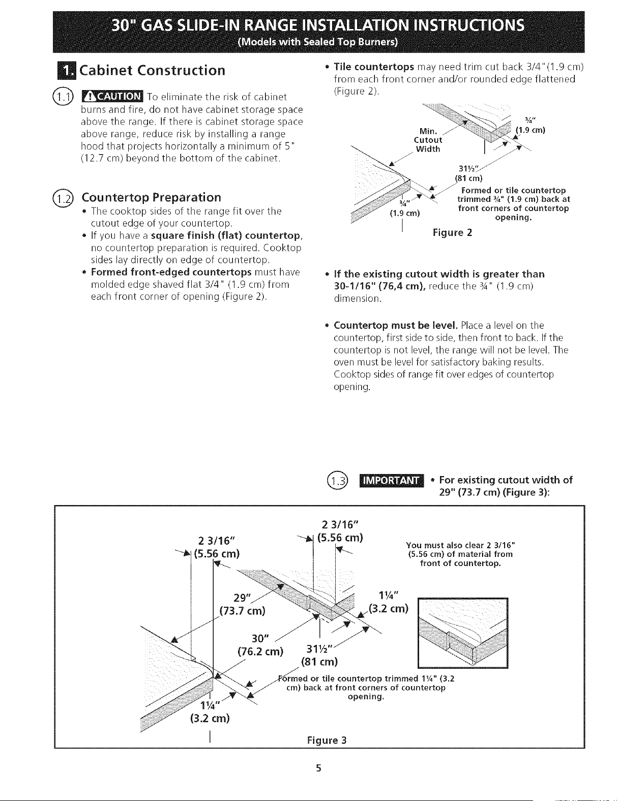
Cou ntertop Preparation
• The cooktop sides of the range fit over the
cutout edge of your countertop.
• If you have a square finish (flat) countertop,
no countertop preparation is required. Cooktop
sides lay directly on edge of countertop.
• Formed front-edged countertops must have
molded edge shaved flat 3/4" (1.9 cm) from
each front corner of opening (Figure 2).
• Tile countertops may need trim cut back 3/4"(1.9 cm)
from each front corner and/or rounded edge flattened
(Figure 2).
Min.
Cutout
Width
(1.9 cm)
I
(1.9cm)
311/z'_
(81 cm)
Formed or tile countertop
trimmed %" (1,9 cm) back at
front corners of countertop
opening.
Figure 2
• if the existing cutout width is greater than
30-1116" (76,4 cm), reduce the 3A" (I .9 cm)
dimension.
Countertop must be level. Place a level on the
countertop, first side to side, then front to back. If the
countertop is not level, the range will not be level. The
oven must be level for satisfactory baking results.
Cooktop sides of range fit over edges of countertop
opening.
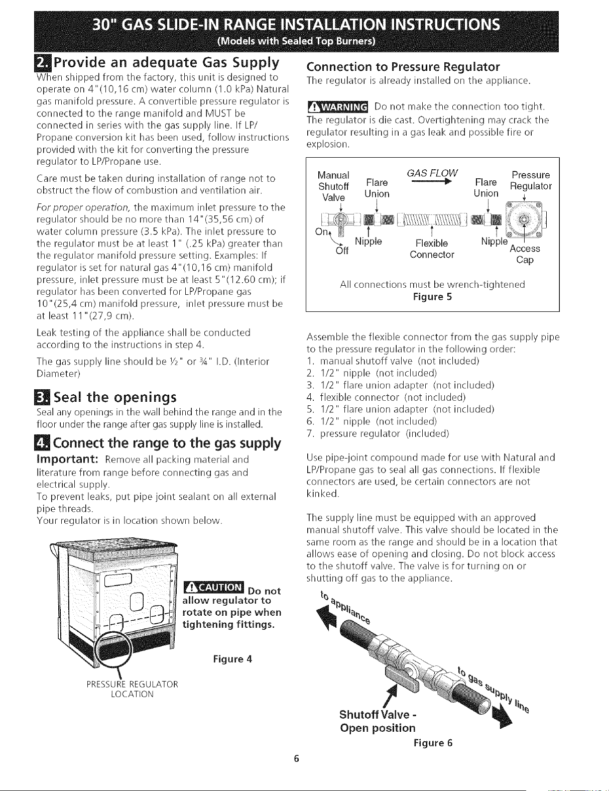
Q • For cutout width of
existing
29" (73.7 cm) (Figure 3):
You must also clear 2 3/16"
(5,56 cm) of material from
front of countertop,
11/4"
.(3.2 cm)
Provide an adequate Gas Supply
When shipped from the factory, this unit is designed to
operate on 4"(10,16 cm) water column (1.0 kPa) Natural
gas manifold pressure. A convertible pressure regulator is
connected to the range manifold and MUST be
connected in series with the gas supply line. If LP/
Propane conversion kit has been used, follow instructions
provided with the kit for converting the pressure
regulator to LP/Propane use.
Care must be taken during installation of range not to
obstruct the flow of combustion and ventilation air.
Forproper operation, the maximum inlet pressure to the
regulator should be no more than 14"(35,S6 cm) of
water column pressure (3.5 kPa). The inlet pressure to
the regulator must be at least 1 " (.25 kPa) greater than
the regulator manifold pressure setting. Examples: If
regulator is set for natural gas 4" (10,16 cm) manifold
pressure, inlet pressure must be at least 5"(12.60 cm); if
regulator has been converted for LP/Propane gas
10"(25,4 cm) manifold pressure, inlet pressure must be
at least 11 "(27,9 cm).
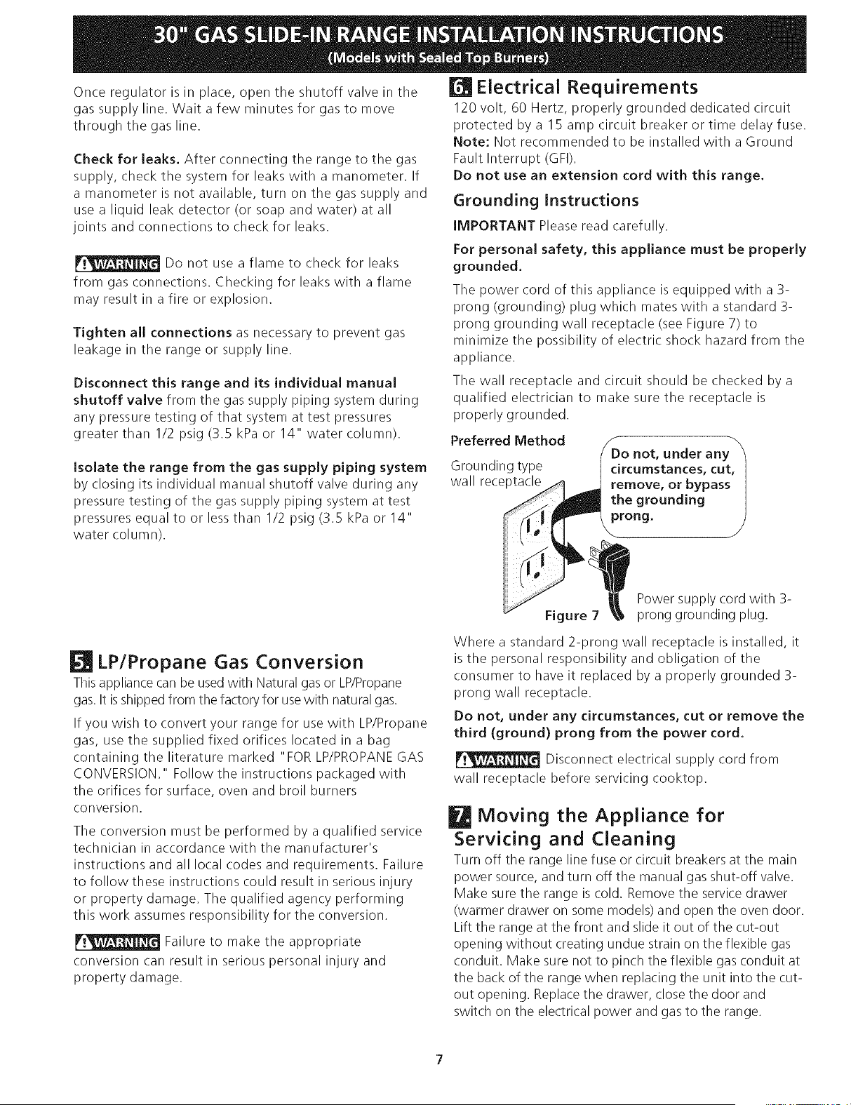
Connection to Pressure ReguJator
The regulator is already installed on the appliance.
Do not make the connection too tight.
The regulator is die cast. Overtightening may crack the
regulator resulting in a gas leak and possible fire or
explosion.
Manual GAS FLOW Pressure
Shutoff Flare _ Flare Regulator
Valve Union Union
On, t t t
Nipple Flexible Nipple Access
Off Connector
Cap
All connections must be wrench-tightened
Figure 5
Leak testing of the appliance shall be conducted
according to the instructions in step 4.
The gas supply line should be Y2" or sA" I.D. (Interior
Diameter)
Seal the openings
Seal any openings in the wall behind the range and in the
floor under the range after gas supply line is installed.
Connect the range to the gas suppJy
Important: Remove all packing material and
literature from range before connecting gas and
electrical supply.
To prevent leaks, put pipe joint sealant on all external
pipe threads.
Your regulator is in location shown below.
Do not
allow regulator to
rotate on pipe when
tightening fittings.
Assemble the flexible connector from the gas supply pipe
to the pressure regulator in the following order:
1. manual shutoff valve (not included)
2. I/2" nipple (not included)
3. 1/2" flare union adapter (not included)
4. flexible connector (not included)
5. 1/2" flare union adapter (not included)
6. I/2" nipple (not included)
7. pressure regulator (included)
Use pipe-joint compound made for use with Natural and
LP/Propane gas to seal all gas connections. If flexible
connectors are used, be certain connectors are not
kinked.
The supply line must be equipped with an approved
manual shutoff valve. This valve should be located in the
same room as the range and should be in a location that
allows ease of opening and closing. Do not block access
to the shutoff valve. The valve is for turning on or
shutting off gas to the appliance.
t_
PRESSURE REGULATOR
LOCATION
Figure 4
Shutoff Valve =
Open position
Figure 6
Onceregulatorisin place,opentheshutoffvalveinthe
gassupplyline.Waita fewminutesfor gasto move
throughthegasline.
Checkfor leaks.Afterconnectingtherangetothe gas
supply,checkthesystemfor leakswith a manometer.If
a manometerisnotavailable,turnonthe gassupplyand
usea liquidleakdetector(orsoapandwater)at all
jointsandconnectionsto checkfor leaks.
Electrical Requirements
120 volt, 60 Hertz, properly grounded dedicated circuit
protected by a 15 amp circuit breaker or time delay fuse.
Note: Not recommended to be installed with a Ground
Fault Interrupt (GFI).
Do not use an extension cord with this range.
Grounding Instructions
IMPORTANT Please read carefully.
Do not use a flame to check for leaks
from gas connections. Checking for leaks with a flame
may result in a fire or explosion.
Tighten all connections as necessary to prevent gas
leakage in the range or supply line.
For personal safety, this appliance must be properly
grounded.
The power cord of this appliance is equipped with a 3-
prong (grounding) plug which mates with a standard 3-
prong grounding wall receptacle (see Figure 7) to
minimize the possibility of electric shock hazard from the
appliance.
Disconnect this range and its individuaJ manuaJ
shutoff valve from the gas supply piping system during
any pressure testing of that system at test pressures
greater than I/2 psig (3.5 kPa or 14" water column).
isolate the range from the gas supply piping system
by closing its individual manual shutoff valve during any
pressure testing of the gas supply piping system at test
pressures equal to or less than I/2 psig (3.5 kPa or 14"
water column).
The wall receptacle and circuit should be checked by a
qualified electrician to make sure the receptacle is
properly grounded.
Preferred Method
Grounding type
wall receptacle
Do not, under any
circumstances, cut,
remove, or bypass
the grounding
prong.
LPIPropane Gas Conversion
Thisappliance can be used with Natural gas or LP/Propane
gas. It is shipped from the factory for usewith natural gas.
If you wish to convert your range for use with LP/Propane
gas, use the supplied fixed orifices located in a bag
containing the literature marked "FOR LP/PROPANEGAS
CONVERSION." Follow the instructions packaged with
the orifices for surface, oven and broil burners
conversion.
The conversion must be performed by a qualified service
technician in accordance with the manufacturer's
instructions and all local codes and requirements. Failure
to follow these instructions could result in serious injury
or property damage. The qualified agency performing
this work assumes responsibility for the conversion.
Failure to make the appropriate
conversion can result in serious personal injury and
property damage.
Figure 7
Power supply cord with 3-
prong grounding plug.
Where a standard 2-prong wall receptacle is installed, it
is the personal responsibility and obligation of the
consumer to have it replaced by a properly grounded 3-
prong wall receptacle.
Do not, under any circumstances, cut or remove the
third (ground) prong from the power cord.
Disconnect electrical supply cord from
wall receptacle before servicing cooktop.
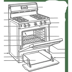
Moving the Appliance for
Servicing and Cleaning
Turn off the range line fuse or circuit breakers at the main
power source, and turn off the manual gas shut-off valve.
Make sure the range is cold. Remove the service drawer
(warmer drawer on some models) and open the oven door.
Lift the range at the front and slide it out of the cut-out
opening without creating undue strain on the flexible gas
conduit. Make sure not to pinch the flexible gas conduit at
the back of the range when replacing the unit into the cut-
out opening. Replace the drawer, close the door and
switch on the electrical power and gas to the range.
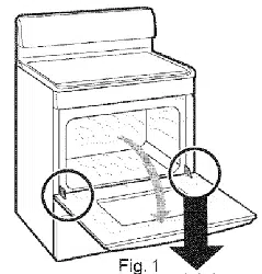
Range Installation
Important Note: Door removal is not a requirement for
installation of the range, but is an added convenience,
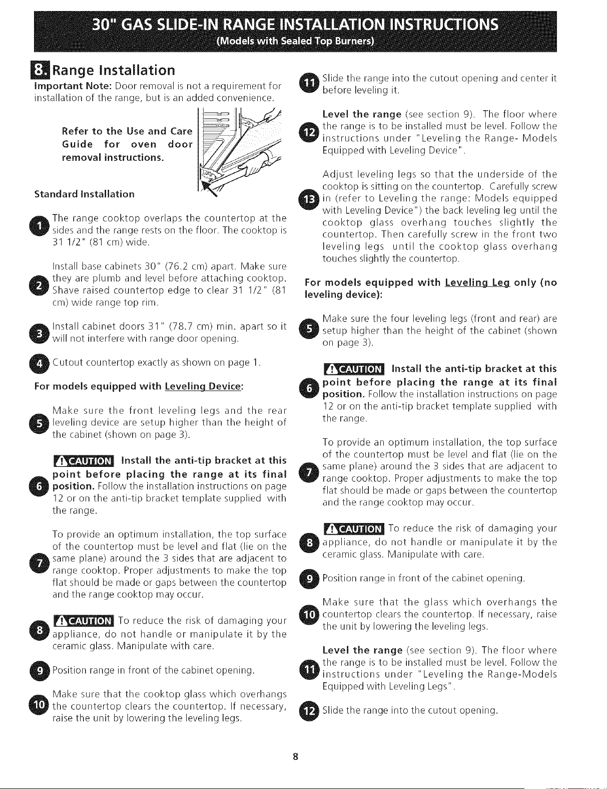
Refer to the Use and Care E
Guide for oven door
removal instructions.
Standard Installation
_The range cooktop overlaps the countertop at the
sides and the range rests on the floor. The cooktop is
31 I/2" (81 cm)wide.
Install base cabinets 30" (76.2 cm) apart. Make sure
_they are plumb and level before attaching cooktop.
Shave raised countertop edge to clear 31 I/2" (81
cm) wide range top rim.
i_lnstall cabinet doors 31 " (78.7 cm) min. apart so it
F
will not interfere with range door opening.
Slide the range into the cutout opening and center it
before leveling it.
Level the range (see section 9). The floor where
the range is to be installed must be level. Follow the
instructions under "Leveling the Range- Models
Equipped with Leveling Device".
Adjust leveling legs so that the underside of the
cooktop is sitting on the countertop. Carefully screw
in (refer to Leveling the range: Models equipped
with Leveling Device") the back leveling leg until the
cooktop glass overhang touches slightly the
countertop. Then carefully screw in the front two
leveling legs until the cooktop glass overhang
touches slightly the countertop.
For models equipped with Leveling Leg only (no
leveling device):
Make sure the four leveling legs (front and rear) are
setup higher than the height of the cabinet (shown
on page 3).
Cutout countertop exactly as shown on page 1.
For models equipped with Leveling Device:
Make sure the front leveling legs and the rear
leveling device are setup higher than the height of
the cabinet (shown on page 3).
Install the anti-tip bracket at this
point before placing the range at its final
position. Follow the installation instructions on page
12 or on the anti-tip bracket template supplied with
the range.
To provide an optimum installation, the top surface
of the countertop must be level and flat (lie on the
same plane) around the 3 sides that are adjacent to
range cooktop. Proper adjustments to make the top
flat should be made or gaps between the countertop
and the range cooktop may occur.
_ To reduce the risk of damaging your
appliance, do not handle or manipulate it by the
ceramic glass. Manipulate with care.
Position range in front of the cabinet opening.
Make sure that the cooktop glass which overhangs
' the countertop clears the countertop. If necessary,
raise the unit by lowering the leveling legs.
Install the anti-tip bracket at this
point before placing the range at its final
position, Follow the installation instructions on page
12 or on the anti-tip bracket template supplied with
the range.
To provide an optimum installation, the top surface
of the countertop must be level and flat (lie on the
same plane) around the 3 sides that are adjacent to
range cooktop. Proper adjustments to make the top
flat should be made or gaps between the countertop
and the range cooktop may occur.
To reduce the risk of damaging your
appliance, do not handle or manipulate it by the
ceramic glass. Manipulate with care.
Position range in front of the cabinet opening.
Make sure that the glass which overhangs the
countertop clears the countertop. If necessary, raise
the unit by lowering the leveling legs.
Level the range (see section 9). The floor where
the range is to be installed must be level. Follow the
instructions under "Leveling the Range-Models
Equipped with Leveling Legs".
Slide the range into the cutout opening.
If Accessories Needed :
Installation For 29" Existing Cutout Width Opening
1. You must replace the actual side trims by new and
smaller side trims. These new side panels can be
ordered through a Sears Service Center.
2. Follow instructions supplied with your new side trim_
to replace the actual side trims with the new ones.
3. Check if the countertop is prepared for 29" cutout
wide opening at page 7.
4. Install range as in the "installation Without Side
Panels" section above.
installation With Backguard
A backguard kit can be ordered through a Sears Service
Center.The cutout depth (21 3/4" (55.2 cm) Min.,
22 I/8" (56.2 era) Max.) needs to be increased to24"
(61 cm) when installing a backguard
Installation With End Panel
An end panel kit can be ordered through a Sears Servio
Center.
Installation With Side Panel
A side panels kit can be ordered through a Sears Servio
Center.
Install cabinet doors 31 " (78.7 cm) rain. apart so as not
to interfere with range door opening.
Leveling the Range
ModeJs Equipped with Leveling Device
Level the range after installation in the cutout
opening.
I. Open the range drawer. The leveling screws
control the height of the rear leg.
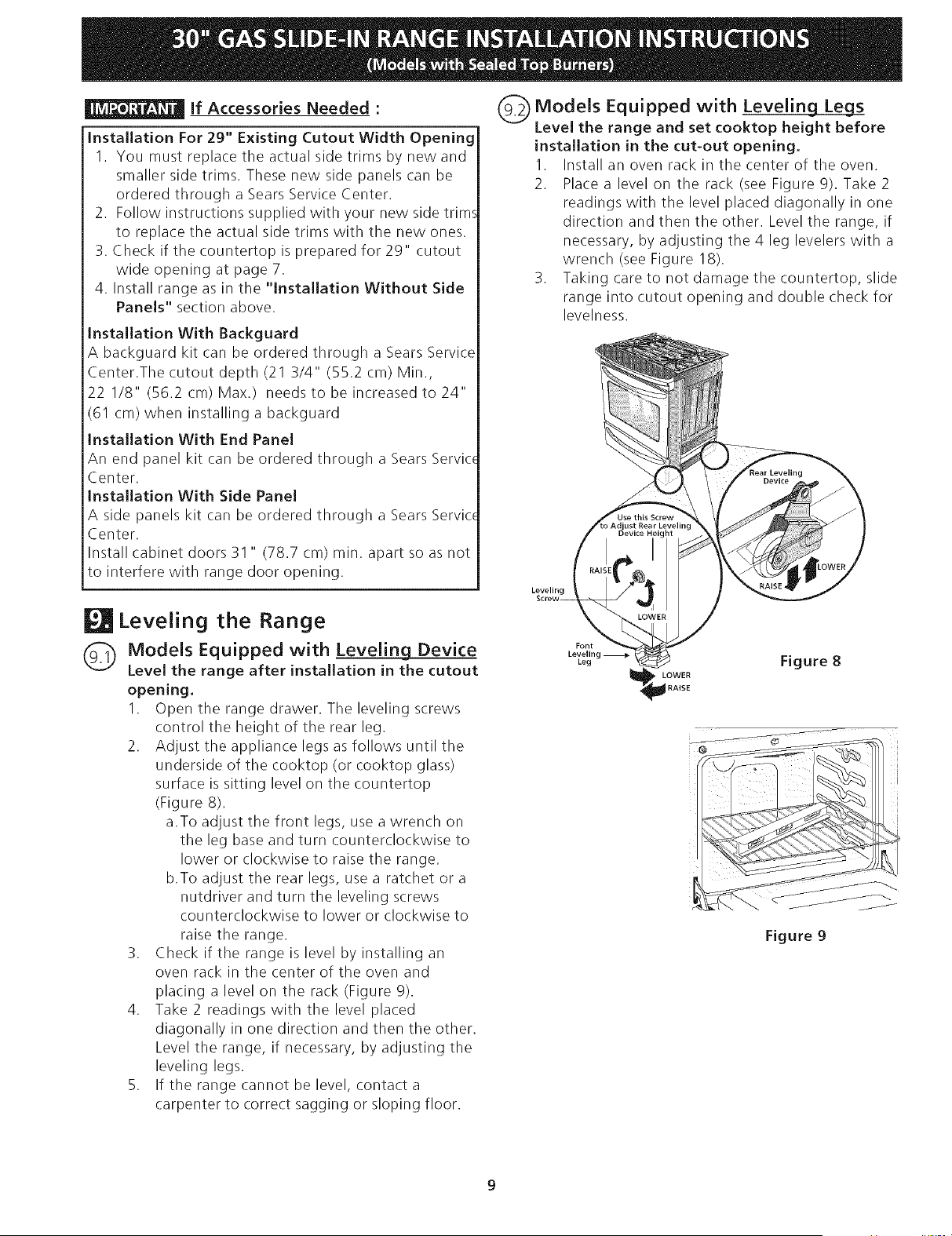
2. Adjust the appliance legs as follows until the
underside of the cooktop (or cooktop glass)
surface is sitting level on the countertop
(Figure 8).
a.To adjust the front legs, use a wrench on
the leg base and turn counterclockwise to
lower or clockwise to raise the range.
b.To adjust the rear legs, use a ratchet or a
nutdriver and turn the leveling screws
counterclockwise to lower or clockwise to
raise the range.
3. Check if the range is level by installing an
oven rack in the center of the oven and
placing a level on the rack (Figure 9).
4. Take 2 readings with the level placed
diagonally in one direction and then the other.
Level the range, if necessary, by adjusting the
leveling legs.
5. If the range cannot be level, contact a
carpenter to correct sagging or sloping floor.
Models Equipped with Leveling Leg_s
Level the range and set cooktop height before
installation in the cut-out opening.
I. Install an oven rack in the center of the oven.
2. Place a level on the rack (see Figure 9). Take 2
readings with the level placed diagonally in one
direction and then the other. Level the range, if
necessary, by adjusting the 4 leg levelers with a
wrench (see Figure 18).
3. Taking care to not damage the countertop, slide
range into cutout opening and double check for
levelness.
Jst Rear Levelim
Leveling
Font
Leveling
Leg
LOWER
RAISE
Figure 8
J @
Figure 9
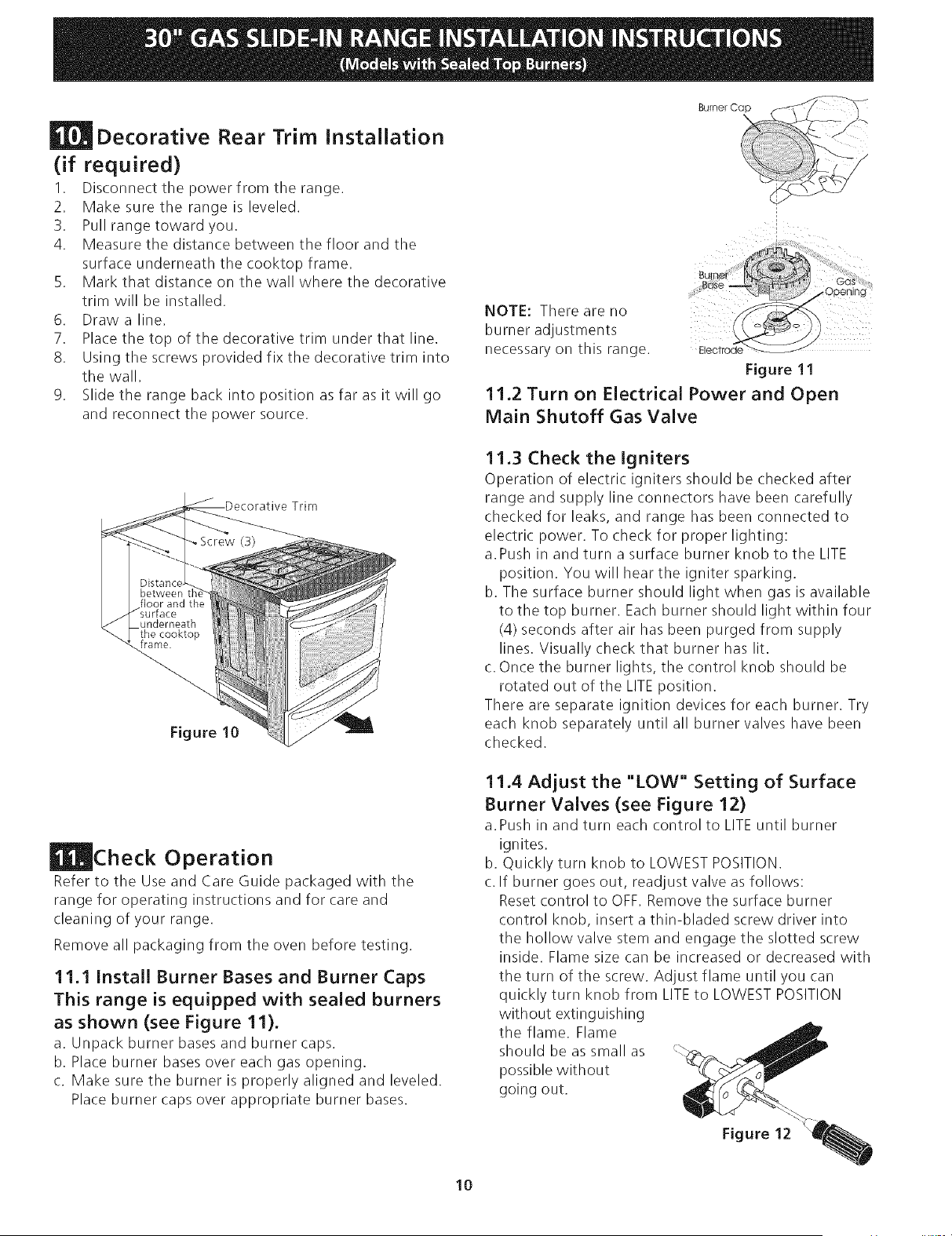
Decorative Rear Trim instaJlation
(if required)
1. Disconnect the power from the range.
2. Make sure the range is leveled.
3. Pull range toward you.
4. Measure the distance between the floor and the
surface underneath the cooktop frame.
5. Mark that distance on the wall where the decorative
trim will be installed.
6. Draw a line.
7. Place the top of the decorative trim under that line.
8. Using the screws provided fix the decorative trim into
the wall.
9. Slide the range back into position as far as it will go
and reconnect the power source.
Figure 10
Check Operation
Refer to the Use and Care Guide packaged with the
range for operating instructions and for care and
cleaning of your range.
Remove all packaging from the oven before testing.
11.1 Install Burner Bases and Burner Caps
This range is equipped with sealed burners
as shown (see Figure 11).
a. Unpack burner bases and burner caps.
b. Place burner bases over each gas opening.
c. Make sure the burner is properly aligned and leveled.
Place burner caps over appropriate burner bases.
NOTE: There are no
burner adjustments
necessary on this range.
Open ng
Electrode
Figure 11
11.2 Turn on Electrical Power and Open
Main Shutoff Gas Valve
11.3 Check the Igniters
Operation of electric igniters should be checked after
range and supply line connectors have been carefully
checked for leaks, and range has been connected to
electric power. To check for proper lighting:
a. Push in and turn a surface burner knob to the LITE
position. You will hear the igniter sparking.
b. The surface burner should light when gas is available
to the top burner. Each burner should light within four
(4) seconds after air has been purged from supply
lines. Visually check that burner has lit.
c. Once the burner lights, the control knob should be
rotated out of the LITE position.
There are separate ignition devices for each burner. Try
each knob separately until all burner valves have been
checked.
11.4 Adjust the "LOW" Setting of Surface
Burner Valves (see Figure 12)
a. Push in and turn each control to LITE until burner
ignites.
b. Quickly turn knob to LOWEST POSITION.
c. If burner goes out, readjust valve as follows:
Reset control to OFF. Remove the surface burner
control knob, insert a thin-bladed screw driver into
the hollow valve stem and engage the slotted screw
inside. Flame size can be increased or decreased with
the turn of the screw. Adjust flame until you can
quickly turn knob from LITE to LOWEST POSITION
without extinguishing
the flame. Flame
should be as small as
possible without
going out.
Figure 12
10
11.5 Operation of Oven Burners and Oven
Adjustments
11.5.1 Electric ignition Burners
Operation of electric igniters should be checked after
range and supply line connectors have been carefully
checked for leaks, and range has been connected to
electric power.
The oven burner is equipped with an electric control
system as well as an electric oven burner igniter. If your
model is equipped with a waist-high broil burner igniter, it
will also have an electric burner igniter. These control
systems require no adjustment. When the oven is set to
operate, current will flow to the igniter. It will "glow"
similar to a light bulb. When the igniter has reached a
temperature sufficient to ignite gas, the electrically
controlled oven valve will open and flame will appear at
the oven burner. There is a time lapse from 30 to 60
seconds after thermostat is turned ON before the flame
appears atthe oven burner. When the oven reaches the
display setting, the glowing igniter will go off. The burner
flame will go "out" in 20 to 30 seconds after igniter goes
"OFF". To maintain any given oven temperature, this
cycle will continue as long as the display is set to operate.
After removing all packing materials and literature from
the oven:
a) Set the oven to BAKE at 300°F. See Use & Care Guide
for operating instructions.
b) Within 60 seconds the oven burner should ignite.
Check for proper flame, and allow the burner to cycle
once. Reset controls to off.
c) If your model is equipped with a high-waist broiler, set
oven to broil. See Use & Care Guide for operating
instructions.
d) Within 60 seconds the broil burner should ignite. Check
for proper flame. Resetcontrols to off.
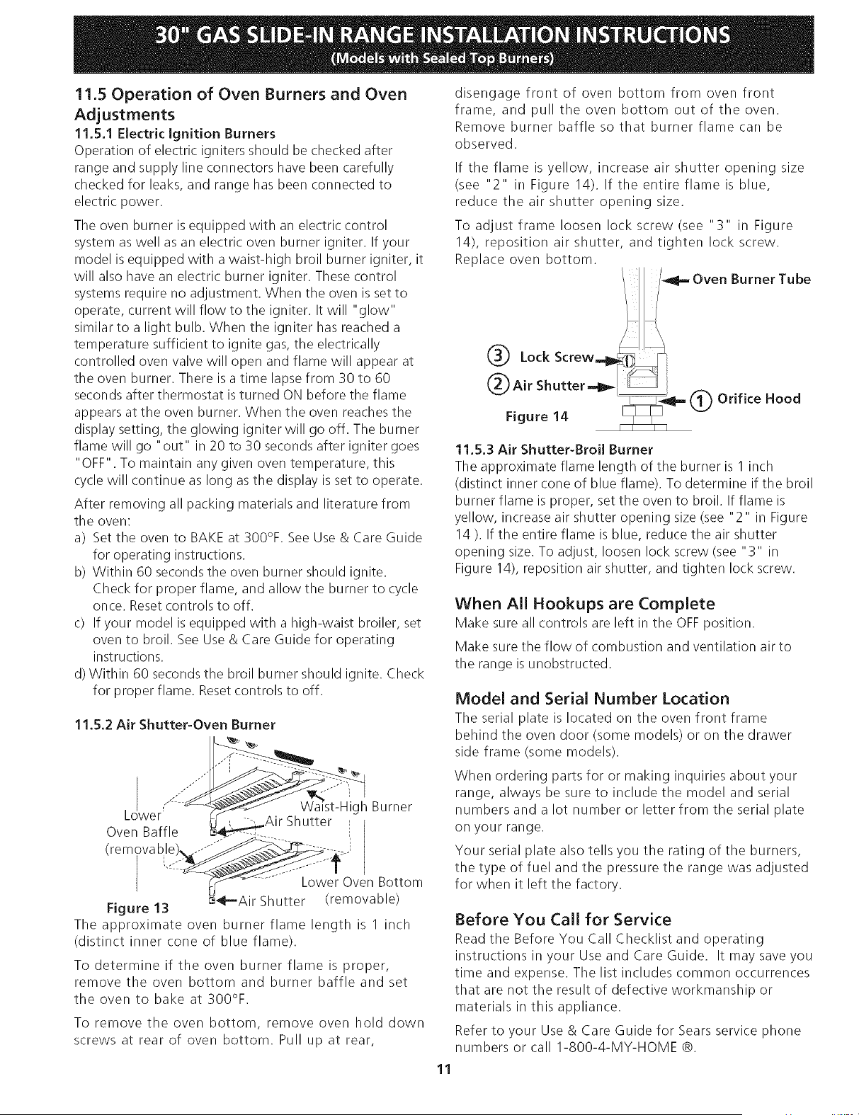
11.5.2 Air Shutter-Oven Burner
j ./../.
L wer: gh Burner
Oven Baffle i
(removable
Lower Oven Bottom
Figure 13 _"-Air Shutter (removable)
The approximate oven burner flame length is 1 inch
(distinct inner cone of blue flame).
To determine if the oven burner flame is proper,
remove the oven bottom and burner baffle and set
the oven to bake at 300%.
To remove the oven bottom, remove oven hold down
screws at rear of oven bottom. Pull up at rear,
disengage front of oven bottom from oven front
frame, and pull the oven bottom out of the oven.
Remove burner baffle so that burner flame can be
observed.
If the flame is yellow, increase air shutter opening size
(see "2" in Figure 14). If the entire flame is blue,
reduce the air shutter opening size.
To adjust frame loosen lock screw (see "3" in Figure
14), reposition air shutter, and tighten lock screw.
Replace oven bottom.
Lock Screw.41_.,t !_I1_ Oven Burner Tube
@FigureAirShutter._ 91_14 @ Orifice Hood
11.5.3 Air Shutter-Broil Burner
The approximate flame length of the burner is 1 inch
(distinct inner cone of blue flame). To determine if the broil
burner flame is proper, set the oven to broil. If flame is
yellow, increase air shutter opening size (see "2" in Figure
14). If the entire flame is blue, reduce the air shutter
opening size. To adjust, loosen lock screw (see "3" in
Figure 14), reposition air shutter, and tighten lock screw.
When All Hookups are Complete
Make sure all controls are left in the OFF position.
Make sure the flow of combustion and ventilation air to
the range is unobstructed.
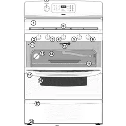
Model and Serial Number Location
The serial plate is located on the oven front frame
behind the oven door (some models or on the drawer
side frame (some models).
When ordering parts for or making inquiries about your
range, always be sure to include the model and serial
numbers and a lot number or letter from the serial plate
on your range.
Your serial plate also tells you the rating of the burners,
the type of fuel and the pressure the range was adjusted
for when it left the factory.
Before You Call for Service
Read the Before You Call Checklist and operating
instructions in your Use and Care Guide. It may save you
time and expense. The list includes common occurrences
that are not the result of defective workmanship or
materials in this appliance.
Refer to your Use & Care Guide for Sears service phone
numbers or call 1-800-4-MY-HOME ®.
11
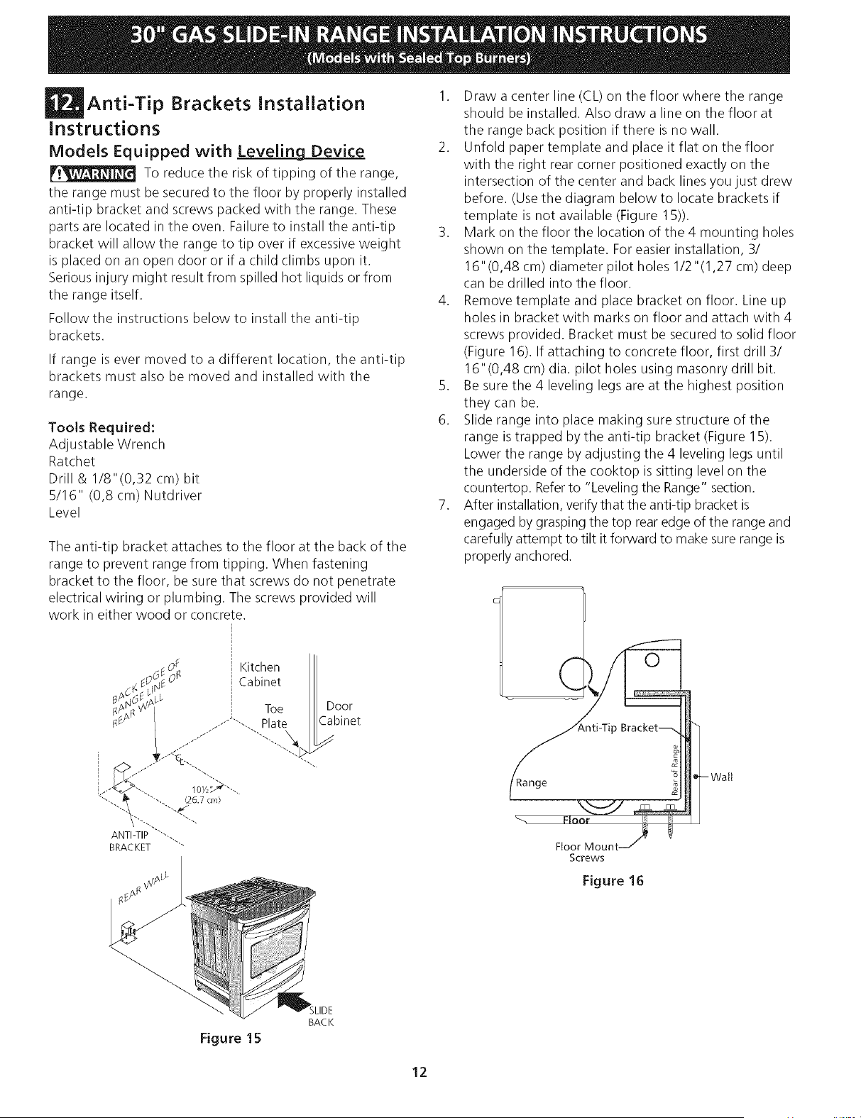
Anti-Tip Brackets installation
Instructions
Models Equipped with Leveling Device
To reduce the risk of tipping of the range,
the range must be secured to the floor by properly installed
anti-tip bracket and screws packed with the range. These
parts are located in the oven. Failure to install the anti-tip
bracket will allow the range to tip over if excessive weight
is placed on an open door or if a child climbs upon it.
Serious injury might result from spilled hot liquids or from
the range itself.
Follow the instructions below to install the anti-tip
brackets.
If range is ever moved to a different location, the anti-tip
brackets must also be moved and installed with the
range.
Tools Required:
Adjustable Wrench
Ratchet
Drill & I/8"(0,32 cm) bit
5/16" (0,8 cm) Nutdriver
Level
The anti-tip bracket attaches to the floor at the back of the
range to prevent range from tipping. When fastening
bracket to the floor, be sure that screws do not penetrate
electrical wiring or plumbing. The screws provided will
work in either wood or concrete.
1. Draw a center line (CL) on the floor where the range
should be installed. Also draw a line on the floor at
the range back position if there is no wall.
2. Unfold paper template and place it flat on the floor
with the right rear corner positioned exactly on the
intersection of the center and back lines you just drew
before. (Use the diagram below to locate brackets if
template is not available (Figure 15)).
3. Mark on the floor the location of the 4 mounting holes
shown on the template. For easier installation, 3/
16"(0,48 cm) diameter pilot holes 1/2"(1,27 cm) deep
can be drilled into the floor.
4. Remove template and place bracket on floor. Line up
holes in bracket with marks on floor and attach with 4
screws provided. Bracket must be secured to solid floor
(Figure 16). If attaching to concrete floor, first drill 3/
16"(0,48 cm) dia. pilot holes using masonry drill bit.
5. Be sure the 4 leveling legs are at the highest position
they can be.
6. Slide range into place making sure structure of the
range is trapped by the anti-tip bracket (Figure 15).
Lower the range by adjusting the 4 leveling legs until
the underside of the cooktop is sitting level on the
countertop. Refer to "Leveling the Range" section.
7. After installation, verify that the anti-tip bracket is
engaged by grasping the top rear edge of the range and
carefully attempt to tilt it forward to make sure range is
properly anchored.
Kitchen
Cabinet
Screws
Figure 16
BAC K
Figure 15
12
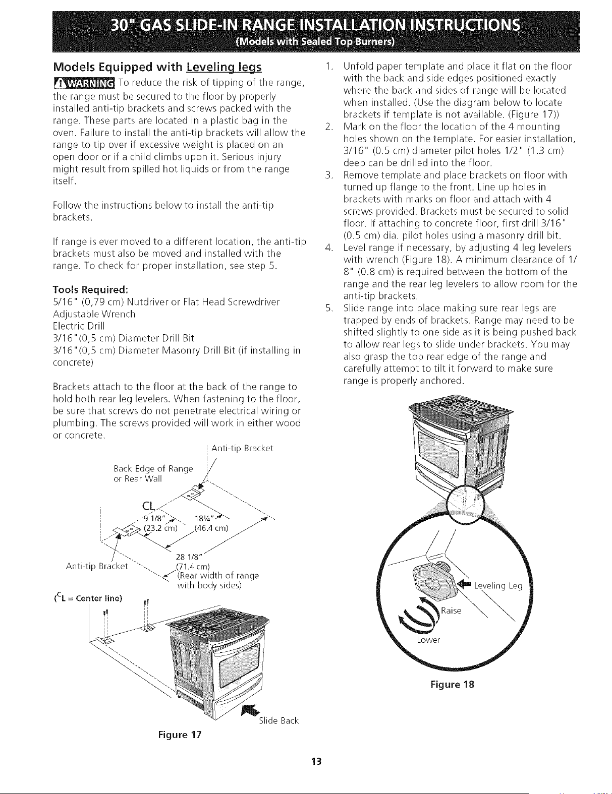
ModeJs Equipped with Leveling leg_s
To reduce the risk of tipping of the range,
the range must be secured to the floor by properly
installed anti-tip brackets and screws packed with the
range. These parts are located in a plastic bag in the
oven. Failure to install the anti-tip brackets will allow the
range to tip over if excessive weight is placed on an
open door or if a child climbs upon it. Serious injury
might result from spilled hot liquids or from the range
itself.
Follow the instructions below to install the anti-tip
brackets.
If range is ever moved to a different location, the anti-tip
brackets must also be moved and installed with the
range. To check for proper installation, see step 5.
Tools Required:
5/16" (0,79 cm) Nutdriver or Flat Head Screwdriver
Adjustable Wrench
Electric Drill
3/16"(0,5 cm) Diameter Drill Bit
3/16"(0,5 cm) Diameter Masonry Drill Bit (if installing in
concrete)
Brackets attach to the floor at the back of the range to
hold both rear leg levelers. When fastening to the floor,
be sure that screws do not penetrate electrical wiring or
plumbing. The screws provided will work in either wood
or concrete.
Anti-tip Bracket
or Rear Wall
i CL<"" ....-.
i .-'9" 1/8">-... 181/4''_'_ _""
/ ""-.. 28 1/8"
Anti-tip Bracket ""--. __(71.4 cm)
""-.._/ (Rear width of range
with body sides)
(CL = Center line)
1. Unfold paper template and place it flat on the floor
with the back and side edges positioned exactly
where the back and sides of range will be located
when installed. (Use the diagram below to locate
brackets if template is not available. (Figure 17))
2. Mark on the floor the location of the 4 mounting
holes shown on the template. For easier installation,
3/16" (0.5 cm) diameter pilot holes 1/2" (1.3 cm)
deep can be drilled into the floor.
3. Remove template and place brackets on floor with
turned up flange to the front. Line up holes in
brackets with marks on floor and attach with 4
screws provided. Brackets must be secured to solid
floor. If attaching to concrete floor, first drill 3/16"
(0.5 cm) dia. pilot holes using a masonry drill bit.
4. Level range if necessary, by adjusting 4 leg levelers
with wrench (Figure 18). A minimum clearance of 1/
8" (0.8 cm) is required between the bottom of the
range and the rear leg levelers to allow room for the
anti-tip brackets.
B. Slide range into place making sure rear legs are
trapped by ends of brackets. Range may need to be
shifted slightly to one side as it is being pushed back
to allow rear legs to slide under brackets. You may
also grasp the top rear edge of the range and
carefully attempt to tilt it forward to make sure
range is properly anchored.
Figure 18
Figure 17
Slide Back
13

NOTES :
LA INSTALACION Y EL SERVIClO DEBEN SER EFECTUADOS POR UN INSTALADOR
CAUFICADO. IMPORTANTE: GUARDE ESTAS INSTRUCClONES PARA USO DEL INSPECTOR LOCAL
DE ELECTRIClDAD. LEA Y GUARDE ESTAS INSTRUCClONES PARA REFERENClA FUTURA.
Si la informad6n contenida en este manual no es seguida exactamente,
puede ocurrir un incendio o e×plosi6n causando daffos materiales, lesi6n personal o la
muerte.
PARASUSEGURIDAD:
-- No almacene ni utilice gasolina u otros vapores y liquidos inflamablesen la proximidad
de _steo de cualquier otro artefacto.
-- QUEDEBEHACERSlPERClBEOLORA GAS:
• No trate de encenderningun artefacto.
• No toque ningun interruptor el_ctrico; no use ningun tel_fono en su edifido.
• Llame a su proveedor de gasdesde el tel_fono de un vecino. Siga las instruccionesdel
proveedorde gas.
• Sino logra comunicarsecon su proveedor de gas,flame al departamento de bomberos.
-- La instalaci6ny el servicio de mantenimiento deben ser efectuados por un instalador
calificado, la agencia de servicio o el proveedor de gas.
Aparatos Instalados en el
estado de Massachusetts;
Este Aparato s61o puede ser
instalado en el estado de
Massachusetts pot un plomero
o ajustador de gas licenciado
de Massachusett.
Este aparato se debe instalar
con un largo conector flexible
de gas de tres (3) pies/36
pulgadas.
Una valvula manual de gas de
tipo manija de forma de "T" se
debe instalar en la linea del
suministro de gas de este
aparato.
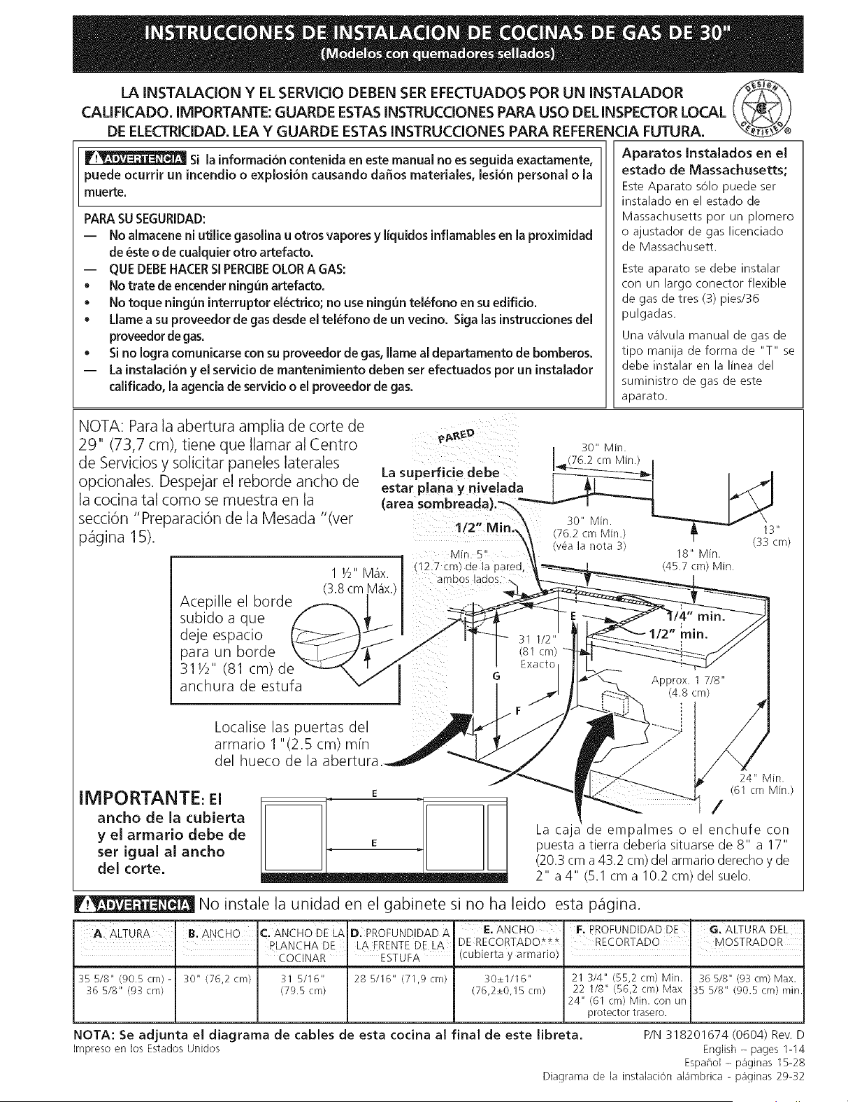
NOTA: Para la abertura amplia de corte de
29" (73,7 cm), tiene que Ilamar al Centro
de Servicios y solicitar paneles laterales
opcionales. Despejar el reborde ancho de
la cocina tal como se muestra en la
secci6n "Preparaci6n de la Mesada "(ver
p_igina 15).
Acepille el borde
subido a que
deje espacio
para un borde
311/2" (81 cm)de
anchura de estufa
Localise las puertas del
armario 1 "(2.5 cm) mfn
del hueco de la
IMPORTANTE: El
ancho de la cubierta
y el armario debe de
ser igual al ancho
del corte.
E
24" Min.
(61 cm Min.)
/
La caja de empalmes o el enchufe con
puesta a tierra deberia situarse de 8" a 17"
(20.3 cm a43.2 cm) del armario derecho y de
2" a 4" (5.1 cm a 10.2 cm) del suelo.
No instale la unidad en el gabinete si no ha leido esta p_flgina.
A ALTURA B.ANcHO c.ANCHoDELA D. PRoFUNDIDADA E. ANCHO F. PROFUNDIDADDE G. ALTURADEL
DE RECORTADO*_*
(cubierta y armario)
35 5/8" @0.5 cm) - 30" (76,2 cm} 31 5/16" 28 5/16" (71,9 cm) 30+_I/16"
36 518" (93 cm} (79.5 cm) (76,2_+0,15 cm)
RECORTADO , MOSTRADOR
21 3/4" (55,2 cm) Min. 36 5/8" (93 cm) Max.
22 1/8" (56,2 cm) Max 35 5/8" (90.5 cm) rain.
24" (61 cm) Min. con Lln
protector trasero.
NOTA: Se adjunta el diagrama de cables de esta cocina al final de este libreta. P/N 318201674 (0604) Rev. D
Impreso en los Estados Unidos English - pages 1-14
Espahol - paginas 15-28
Diagrama de la instalaci6n al_imbrica - p_iginas 29-32
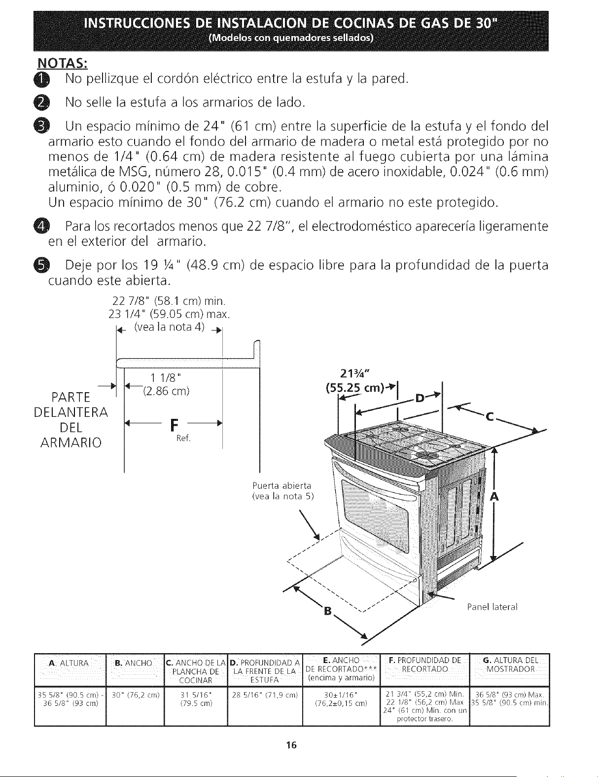
NOTAS:
el No pellizque el cord6n el_ctrico entre la estufa y la pared.
O No selle la estufa a los armados de lado.
Un espado minimo de 24" (61 cm) entre la superficie de la estufa y el fondo del
armado esto cuando el fondo del armado de madera o metal est,1 protegido por no
menos de 1/4" (0.64 cm) de madera resistente al fuego cubierta por una I_flmina
met_qlica de MSG, nOmero 28, 0.015" (0.4 ram) de acero inoxidable, 0.024" (0.6 ram)
aluminio, 6 0.020" (0.5 ram) de cobre.
Un espado minimo de 30" (76.2 cm) cuando el armado no este protegido.
_11 Para los recortados menos que 22 7/8", el electrodom_stico apareceria ligeramente
en el exterior del armado.
Deje por los 19 1/4" (48.9 cm) de espacio libre para la profundidad de la puerta
cuando este abierta.
PARTE
DELANTERA
DEL
ARMARIO
22 7/8" (58.1 cm) min.
23 1/4" (59.05 cm) max.
__ (vea la nota 4) ÷
F
1 1/8"
°(2.86 cm)
F
Ref.
21¾"
(55.25 cm)4P
Puerta abierta
(yea la nota 5) A
Panel lateral
qC:ANCHO DE LAD. PROFUNDIDAD A
I PLANCHA DE LA FRENTE DE LA
' COCINAR ' ESTUFA
35 5/8" (90.5cm)- 30" (76,2 cm} 31 5/16" 28 5/16" (71,9cm}
36 518" (93 cm} (79.5 cm)
E. ANCHO
DE RECORTADO***
(encima y armario)
F. PROFUNDIDAD DE G. ALTURA DEL
30±1116" 21 3/4" (55,2 cm) Min. 36518" (93 cm} Max.
(76,2±0,15cm) 22 118" (56,2 cm}Max 35 518" (90.Scm) min.
24" (61 cm} Min. con tin
protector trasero.
16
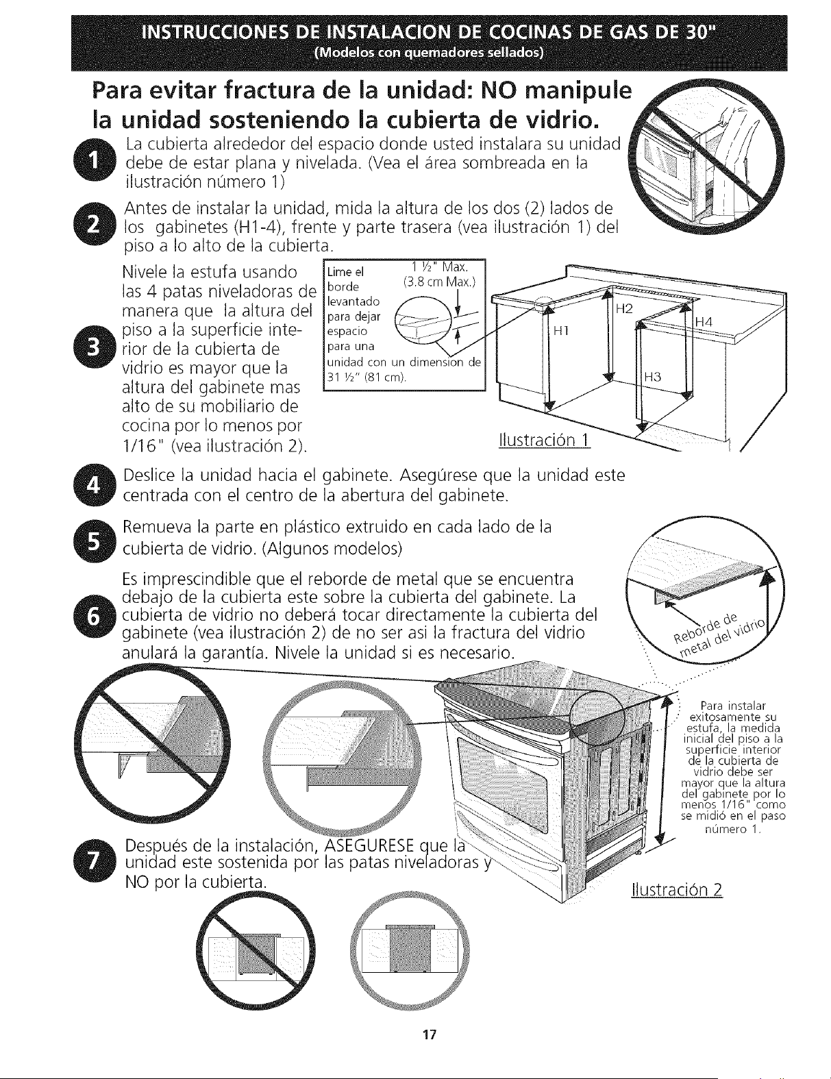
Para evitar fractura de la unidad: NO manipule
la unidad sosteniendo la cubierta de vidrio.
La cubierta alrededor del espacio donde usted instalara su unidad
debe de estar plana y nivelada. (Vea el _irea sombreada en la
ilustraciOn numero 1)
Antes de instalar la unidad, mida la altura de los dos (2)lados de
los gabinetes (H1-4), frente y parte trasera (vea ilustracion 1) del
piso a Io alto de la cubierta.
Nivele la estufa usando
las 4 patas niveladoras de
manera que la altura del
piso a la superficie inte-
rior de la cubierta de
vidrio es mayor que la
altura del gabinete mas
alto de su mobiliario de
cocina pot Io menos pot
1/1 6" (vea ilustraci0n 2).
Limeel 1 1/2"Max.
borde (3.8 cm Max.)
levantado _
para dejar
espaclo
para una
unidad con
31 Y2" (81 cm).
Ilustracion 1
/
Deslice la unidad hacia el gabinete. Aseg0rese que la unidad este
centrada con el centro de la abertura del gabinete.
Remueva la parte en pl_istico extruido en cada lado de la
cubierta de vidrio. (Algunos modelos)
Es imprescindible que el reborde de metal que se encuentra
debajo de la cubierta este sobre la cubierta del gabinete. La
cubierta de vidrio no deber_i tocar directamente la cubierta del
gabinete (vea ilustracion 2) de no set asi la fractura del vidrio
anular_i la garantia. Nivele la unidad si es necesario.
Despues de la instalacion, ASEGURESE ue
unidad este sostenida pot las patas
NO pot la cubierta.
\
: Para instalar
exitosamente su
estufa la medida
inicial del Riso a la
superficie interior
de la cubierta de
vidrio debe ser
mayor que la altura
del gabmete pot Io
menos 1/16" como
se midio en el paso
n0mero 1.
Ilustracion 2
17
Notas importantes para el Instalador
1. Lea todas las instrucciones contenidas en este manual
antes de instalar la estufa.
2. Saque todo el material usado en el embalaje del
compartimiento del homo antes de conectar el
suministro electrico o de gas a la estufa.
3. Observe todos los cOdigos y reglamentos pertinentes.
4. Deje estas instrucciones con el comprador.
Nota Importante para el Consumidor
Conserve estas instrucciones y el Manual del Usuario para
referencia futura.
IMPORTANTES
INSTRUCCIONES DE
SEGURIDAD
Instalaci6n de esta estufa debe cumplir con todos los
cOdigos locales, o en ausencia de cOdigos locales con el
COdigo National de Gas Combustible ANSI Z223.1/NFPA
.54--01tima edition.
El diseflo de esta estufa ha sido certificado por la CSA
International. En este como en cualquier otro artefacto
que use gas y genere calor, hay ciertas precauciones de
seguridad que usted debe seguir. Estas ser_in encontradas
en el Manual del Usuario, lealo cuidadosamente.
• Asegurese de que la estufa sea instalada y
conectada a tierra en forma apropiada por un
instalador calificado o por un t_cnico.
• Esta estufa debe ser el_ctricamente puesta a tierra
de acuerdo con los codigos locales, o en su
ausencia, con el Codigo El_ctrico National ANSI/
NFPA No. 70, ultima edition. Vea las instrucciones
para la puesta a tierra en la p_igina 4.
• Antes de instalar la estufa en un area cuyo piso
este recubierto con linoleo u otro tipo de piso
sint_tico, asegurese de que _stos puedan resistir
una temperatura de por Io menos 90°F sobre la
temperatura ambiental sin provocar encogimiento,
deformaciOn o decoloraci6n. No instale la estufa
sobre una alfombra al menos que coloque una plancha
de material aislante de por Io menos 1/4 pulgada,
entre la estufa y la alfombra.
• Todas las
estufas
pueden
! volcarse.
• Esto podria
resultar en
lesiones
personales.
• Instale el
d ispositivo
antivuelcos
que se ha
empacado
junto con
esta estufa.
Para reducir el riesgo de
que se vuelque la estufa,
hay que asegurarla
adecuadamente colo
candole los soportes
antivuelco que se
proporcionan. Para
comprobar si estos estan
instalados y apretados en
su lugar como se debe,
ase el borde trasero
superior de la estufa y
cuidado samente incline la
hacia adelante para
asegurar que la estufa se
ancle.
• Asegurese de que el material que recubre las
paredes alrededor de la estufa, pueda resistir el
calor generado pot la estufa.
• No obstruya el flujo del aire de combusti6n en la
ventilacion del homo ni tampoco alrededor de la
base o debajo del panel inferior delantero de la
estufa. Evitetocar las aberturaso _ireascercanas de
la ventilaciOn, ya que pueden estar muy calientes
duranteel funcionamiento del horno. La estufa
requiere aire fresco para la combustion apropiada de
los quemadores.
Nunca deje ni_os solos o
desatendidos en un area donde un artefacto esta
siendo usado. A medida que los nihos crecen,
ense_eles el uso apropiado y de seguridad para todos los
artefactos. Nunca deje la puerta del homo abierta
cuando la estufa est,1 desatendida.
No se pare, apoye o siente en las
puertas o cajones de esta estufa pues puede resultar
en serias lesiones y puede tambien causar da6o a la
estufa.
• No almacene articulos que puedan interesar a los
ni_os en los gabinetes sobre la estufa. Los nihos
pueden quemarse seriamente tratando de trepar a la
estufa para alcanzar estos articulos.
• Los gabinetes de almacenamiento sobre la estufa
deben set evitados, para eliminar la necesidad de
tenet que pasar sobre los quemadores superiores
de la estufa para Ilegar a ellos.
• Ajuste el tama_o de la llama de los quemadores
superiores de tal manera que _sta no sobrepase el
borde de los utensilios decocinar. La llama
excesiva es peligrosa.
• No use el homo como espacio de almacenaje. Esto
create1 una situaciOn potencialmente peligrosa.
• Nunca use la estufa para calentar el cuarto. El uso
prolongado de la estufa sin la adecuada ventilaciOn
puede resultar peligroso.
• No almacene ni utilice gasolina u otros vapores y
liquidos inflamables en la proximidad de _ste o de
cualquier otto artefacto el_ctrico. Puede provocar
incendio o explosion.
• En caso de una interruption del servicio electrico, es
posible de encender los quemadores de superficie a
mano. Para encender un quemador de superficie,
acerque un fOsforo encendido del cabezal del
quemador, y gire delicadamente el botOn de control de
superficie a LITE (encendido). Tenet cuidado al
encender los quemadores a mano.
• Ajuste todos los controles a la posici6n "OFF"
(apagada) despu_s de haber hecho una operaci6n
con tiempo programado.
PARA MODELOS AUTOLIMPIANTES:
• Saque la asadera, alimentos o cualquier otro
utensilio antes de usar el ciclo de autolimpieza del
homo. Limpietodoexcesode derrame dealimentos.
Siga las instrucciones de prelimpiado en el Manual del
Usuario.
• A diferenda de la gama estandar cocinas de gas,
ESTA PLANCHA DE COCINA NO ES MOVlBLE. No
intente quitar la plancha de cocina.
18
Construccion del armario
F._I_I Para eliminar el riesgo de quemaduras o
de fuego tratando de alcanzar algo por encima de las
zonas calientes, evite de colocar articulos sobre la cocina.
Si cree necesitar este espacio, el riesgo puede disminuir si
instala un sombrerete que proteja horizontalmente un
minimo de 5" (12.7cm) sobre la base del armario.
Preparacion del mostrador
• Las extremidades de la cocina sobrepasan el horde de
su mostrador.
• Si tiene un mostrador con las extremidades
cuadradas (planas), no se necesita ninguna
preparaciOn del mostrador.
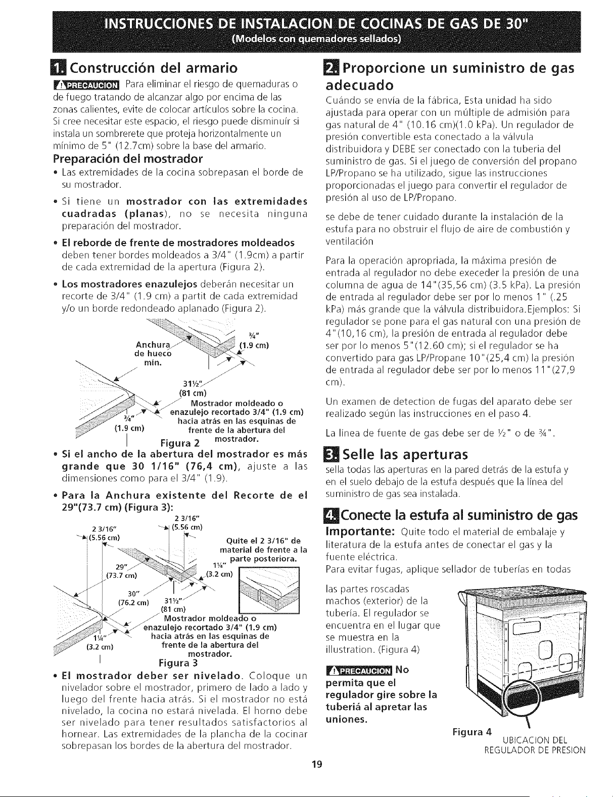
• El reborde de frente de mostradores moldeados
deben tenet hordes moldeados a 3/4" (1.9cm) a partir
de cada extremidad de la apertura (Figura 2).
• Los mostradores enazulejos deberan necesitar un
recorte de 3/4" (1.9 cm) a partit de cada extremidad
y/o un horde redondeado aplanado (Figura 2).
(81cm)
J Mostrador moldeado o
enazuiejo recortado 3/4" (1,9 cm)
hada atr_s en tas esquinas de
(1,9 cm) frente de la abertura del
I Figura 2
mostrador.
• Si el ancho de la abertura del mostrador es m_s
grande que 30 1/16" (76,4 cm), ajuste a las
dimensiones corno para el 3/4" (1.9).
• Para la Anchura existente del Recorte de el
29"(73.7 cm) (Figura 3):
2 3/16"
2 3/16" _ (5.56 cm)
_!(5.56 cm) _ Quite el 2 3/16" de
[_ material de frente a Ja
/ _"_--L I / _ parte posteriora.
| 1W"
I I (73 .2 cm) I .
._ _3 "
-_'-.. I (76.2 cm) "
"<_._ _ /(81 cm) I ...."_'4r¢/
J_4k_ _ Mostrador moldeado o
ulejo recortado 3/4" (1,9 cm)
cia atr_s en las esquinas de
frente de la abertura dee
mostrador,
I Figura 3
• El mostrador deber set niveJado. Coloque un
nivelador sobre el mostrador, primero de lado a lado y
luego del frente hacia atras. Si el mostrador no esta
nivelado, la cocina no estara nivelada. El homo debe
set nivelado para tenet resultados satisfactorios al
hornear. Las extremidades de la plancha de la cocinar
sobrepasan los hordes de la abertura del mostrador.
FJl Proporcione un suministro de gas
adecuado
Cuando se envia de la fabrica, Esta unidad ha sido
ajustada para operar con un mOltiple de admisiOn para
gas natural de 4" (10.16 cm)(1.0 kPa). Un regulador de
presiOn convertible esta conectado a la valvula
distribuidora y DEBE set conectado con la tuberia del
suministro de gas. Si eljuego de conversion del propano
LP/Propano se ha utilizado, sigue las instrucciones
proporcionadas el juego para convertir el regulador de
presiOn al uso de LP/Propano.
se debe de tenet cuidado durante la instalaciOn de la
estufa para no obstruir el flujo de aire de combustion y
ventilaciOn
Para la operaciOn apropriada, la maxima presiOn de
entrada al regulador no debe execeder la presiOn de una
columna de agua de 14"(35,56 cm) (3.5 kPa). La presiOn
de entrada al regulador debe set pot Io menos I " (.25
kPa) mas grande que la valvula distdbuidora.Ejemplos: Si
regulador se pone para el gas natural con una presiOn de
4"(10,16 cm), la presiOn de entrada al regulador debe
set pot Io menos 5"(12.60 cm); si el regulador se ha
convertido para gas LP/Propane 10"(25,4 cm)la presiOn
de entrada al regulador debe set pot Io menos 11 "(27,9
cm).
Un examen de detection de fugas del aparato debe ser
realizado seg0n las instrucciones en el paso 4.
La linea de fuente de gas debe set de Y2" o de 3A".
Selle las aperturas
sella todas las aperturas en la pared detras de la estufa y
en el suelo debajo de la estufa despu_s que la linea del
suministro de gas sea instalada.
Conecte la estufa al suministro de gas
Importante: Quite todo el material de embalaje y
literatura de la estufa antes de conectar el gas y la
fuente el_ctrica.
Para evitar fugas, aplique sellador de tuberias en todas
las partes roscadas
machos (exterior) de la
tuberia. El regulador se
encuentra en el lugar que
se muestra en la
illustration. (Figura 4)
No
permita que el
regulador gire sobre la
tuberi_ al apretar las
uniones.
Figura 4
UBICACION DEL
REGULADOR DE PRESION
19
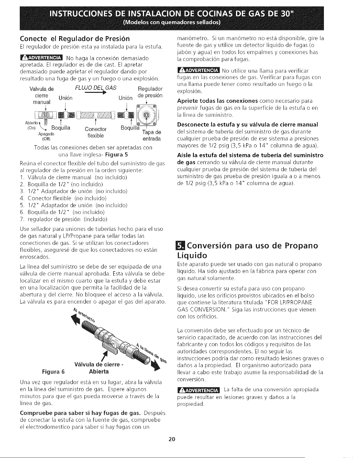
Conecte el ReguJador de Presi6n
El regulador de presiOn esta ya instalada para la estufa.
V.__ No haga la conexiOn demasiado
apretada. El regulador es de die cast. El apretar
demasiado puede agrietar el regulador dando por
resultado una fuga de gas y un fuego o una explosion.
Valvula de FLUJO DEL GAS Regulador
_" de presi6n
cierre Uni6n UniOn
manual
Abier_ _ [ i'_ii-[_i ] _ _t
(on) X.. Boquilla Conector Boquill_
Apagado flexible Tapa de
(Off) entrada
Todas las conexiones deben ser apretadas con
una Ilave inglesa- Figura 5
ReOna el conector flexible del tubo del suministro de gas
al regulador de la presiOn en la orden siguiente:
I. Valvuladecierremanual (noincluido)
2. Boquilla de 1/2" (no incluido)
3. 1/2" Adaptador de union (no incluido)
4. Conectorflexible (no incluido)
5. 1/2" Adaptador de union (no incluido)
6. Boquilladel/2" (noincluido)
7. regulador de presiOn (incluido)
Use sellador para uniones de tuberias hecho para el uso
de gas natural y LP/Propane para sellar todas las
conectiones de gas. Si se utilizan los conectadores
flexibles, asegurese de que los conectadores no estan
enroscados.
La linea del suministro se debe de ser equipada de una
valvula de cierre manual aprobada. Esta valvula se debe
Iocalizar en el mismo cuarto que la estufa y debe estar
en una IocalizaciOn que permita la facilidad de la
abertura y del cierre. No bloquee el acceso a la valvula.
La valvula es para encender o apagar el gas del aparato.
AI
manOmetro. SiunmanOmetronoestadisponible, girela
fuente de gas y utilice un detector liquido de fugas (o
jabOn y agua) en todos los empalmes y conexiones has
la comprobaciOn para fugas.
F.__ No utilice una llama para verificar
fugas en las conexiones de gas. Verificar para fugas con
una llama puede tener como resultado un fuego o la
explosion.
Apriete todas las conexiones como necesario para
prevenir fugas de gas en la superficie de la estufa o en
la linea de suministro.
Desconecte la estufa y su v_lvula de cierre manual
del sistema de tuberia del suministro de gas durante
cualquier prueba de presiOn de ese sistema a presiones
mayores de 1/2 psig (3,5 kPa o 14" columna de agua).
Aisle la estufa del sistema de tuberia del suministro
de gas cerrando su valvula de cierre manual durante
cualquier prueba de presiOn del sistema de tuberia del
suministro de gas prueba de presion iguala a o a menos
de 1/2 psig (3,5 kPa o 14" columna de agua).
Conversi6n para uso de Propano
Liquido
Este aparato puede ser usado con gas natural o propano
liquido. Ha sido ajustado en la %brica para operar con
gas natural solamente.
Si desea convertir su estufa para uso con propano
liquido, use los orificios provistos ubicados en el bolso
que contiene la literatura titulada "FOR LP/PROPANE
GAS CONVERSION." Siga las instrucciones que vienen
con los orificios.
V_lvula de cierre -
Figura 6 AbJerta
Una vez que regulador esta en su lugar, abra la valvula
enlalineadelsuministrodegas. Esperealgunos
minutos para que el gas pueda moverse a travOs de la
linea de gas.
Compruebe para saber si hay fugas de gas. Despues
de conectar la estufa con la fuente de gas, compruebe
el electrodomestico para saber si hay fugas con un
La conversion debe ser efectuado por un tOcnico de
servicio capacitado, de acuerdo con las instrucciones del
fabricante y con todos los cOdigos y requisitos de las
autoridades correspondentes. El no seguir las
instrucciones podria dar como resultado lesiones graves o
dahosalapropiedad. EIorganismoautorizadopara
Ilevar a cabo este trabajo asume la responsabilidad de la
conversion.
La falta de una conversion apropiada
puede resultar en lesiones graves y daflos a la
propiedad.
20
Requisitos eJ6ctricos
120 voltio, 60 Hertzio, circuito dedicado apropiadamente
puestos a tierra protegido por un circuito de amperio o
fusible de demora de tiempo de 15 amp. Nora: no es
recomendado instalarlo con un Interruptor (GFI) de
puesta a tierra.
No utilice una extensi6n con esta estufa.
Instrucdones de puesta a tierra
IMPORTANTE Por favor lea con cuidado.
Para la seguridad personal, este aparato debe set
puesto a tierra apropiadamente.
El cable del suministro electrico de esta estufa esta
equipado con un enchufe de tres patillas (para puesta a
tierra) que coincida con un enchufe de pared estandar
con puesta a tierra de tres patillas para minimizar la
posibilidad que se produzcan descargas el_ctricas.
El cliente debera encargar a un t6cnico para asegurarse
de que el enchufe se encuentra debidemente conectado
a tierra y polarizado.
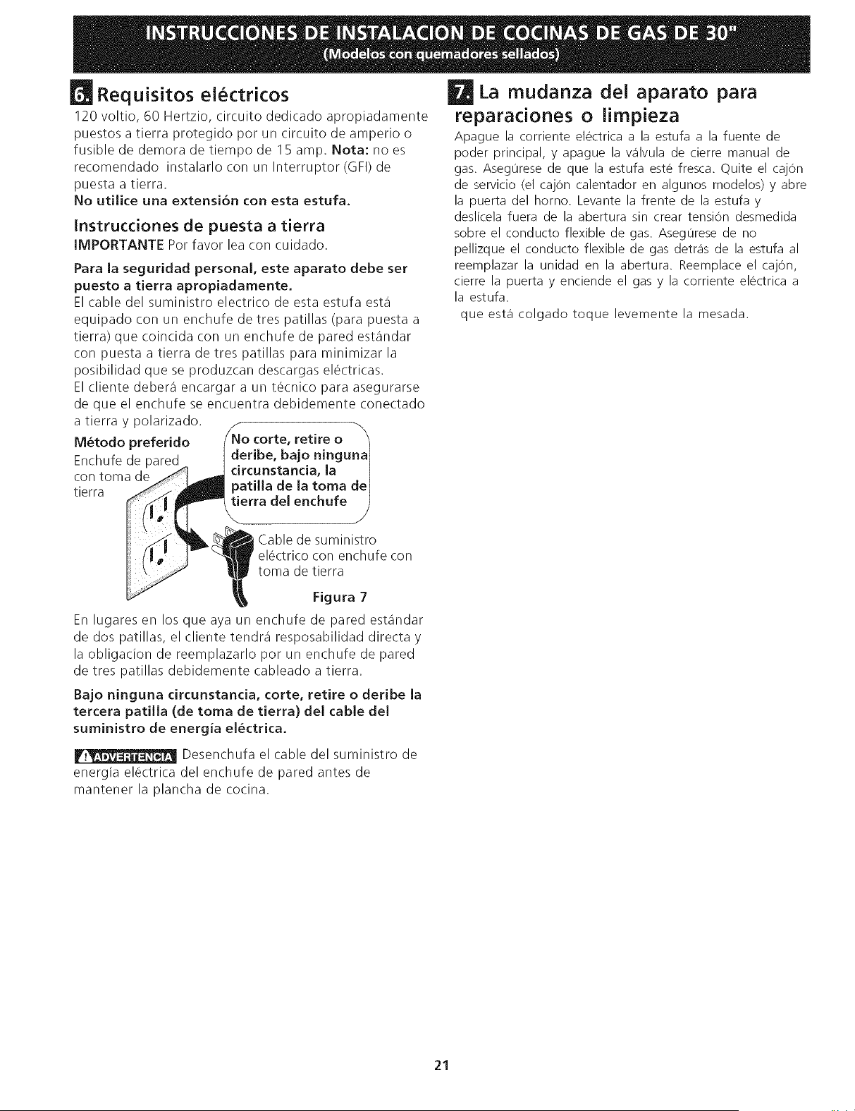
M6todo preferido corte, retire o
deribe, bajo ninguna I
Enchufe de pared circunstancia, la
con toma de patilla de la toma de I
tierra tierra del enchufe J
Cable de suministro
el_ctrico con enchufe con
toma de tierra
La mudanza del aparato para
reparaciones o limpieza
Apague la corriente electrica a la estufa a la fuente de
poder principal, y apague la wilvula de cierre manual de
gas. Asegurese de que la estufa este fresca. Quite el cajOn
de servicio (el cajOn calentador en algunos modelos) y abre
la puerta del horno. Levante la frente de la estufa y
deslicela fuera de la abertura sin crear tension desmedida
sobre el conducto flexible de gas. Asegurese de no
pellizque el conducto flexible de gas detr_is de la estufa al
reemplazar la unidad en la abertura. Reemplace el cajOn,
cierre la puerta y enciende el gas y la corriente electrica a
la estufa.
que est,1 colgado toque levemente la mesada.
Figura 7
En lugares en los que aya un enchufe de pared estandar
de dos patillas, el cliente tendra resposabilidad directa y
la obligation de reemplazarlo por un enchufe de pared
de tres patillas debidemente cableado a tierra.
Bajo ninguna circunstancia, corte, retire o deribe Ja
tercera patilla (de toma de tierra) deJ cable deJ
suministro de energia eJ6ctrica.
F__ Desencbufa el cable del suministro de
energia el_ctrica del encbufe de pared antes de
mantener la plancba de cocina.
21
instalaci6n de la estufa
Deslice la unidad hacia el gabinete y c_ntrela antes
de nivelada.
Nota importante: No es necesario, pero si es
conveniente, quitar la puerta para instalar el horno.
Consulte las instrucciones para retirar la puerta en la Guia
de Uso y Cuidado.
InstaJaci6n sin paneJ(es) JateraJ(es).
Nivele la codna (vea NivelaciOn de la estufa). El
piso donde se instala la cocina debe estar nivelado.
Siga las instrucciones "nivelaci6n de la estufa-
modelos equipado con un sistema de dispositivo de
nivelaciOn ").
La plancha de cocinar se sobrepone por encima del
mostrador con sus extremidades y la cocina reposa
sobre el suelo. La plancha de cocinar es 31 1/2" (81
cm) de ancho.
Instale la base de los armarios a 30" (76.2 cm) de
espacio entre elias. Aseg0rese que estos esten
verticales y alineados antes de instalar la plancha de
cocinar. Lije el horde del mostrador para obtener las 31
1/2 (81 cm)" en la parte superior del mostrador.
Instale las puertas del armario a 31 " (78,7 cm) de
espacio entre elias para que no interfieran con la
abertura de la puerta de la cocina.
Corte el mostrador exactamente como en la pagina I.
Ajuste alas patas de nivelaci6n de manera que la
parte de abajo de la plancha de cocinar esta
apoyada contra el mostrador. Atomille con cuidado
en la pata de nivelaci6n trasera hasta que el vidrio
que esta colgado toque levemente la cubierta. El
vidrio debe soportar el peso de la unidad. Luego,
atomille con cuidado en las dos patas de nivelaci6n
anteriores (igual a 15) hasta que el vidrio que esta
colgado toque levemente la cubierta.
Para los modelos equipado con las patas
niveladoras:
AsegOrese que el frente de las patas niveladoras y el
dispositivo de nivelaci6n posterior esten ajustados
mas altos que la altura del gabinete (vea pagina 3).
Para los modelos equipado con un sistema de
dispositivo de nivelad6n:
Aseg0rese que el frente de las patas niveladoras y el
dispositivo de nivelaci6n posterior esten ajustados mas
altos que la altura del gabinete (vea pagina 3).
I_.t__ Instale el soporte anti-inclinaci6n
de acuerdo alas instrucciones del patr6n anti-
inclinaci6n ( si no Io tiene vea la pagina 23).
Instale el soporte anti-inclinaci6n
de acuerdo alas instrucciones del patr6n anti-
inclinaci6n ( si no Io tiene vea la pagina 23).
Para una instalaci6n 6ptima, la superficie superior de
la cubierta debe estar nivelada y ser plana (sobre el
mismo piano) en los 3 lados adyacentes a la c. Se
deben hater los ajustes correspondientes para hater
que la parte superior quede plana, de Io contrario
podran quedar espacios entre la cubierta y la cocina.
Para una instalaci6n 6ptima, la superficie superior de
la cubierta debe estar nivelada y ser plana (sobre el
mismo piano) en los 3 lados adyacentes a la cocina.
Se deben hater los ajustes correspondientes para
hater que la parte superior quede plana, de Io
contrario podran quedar espacios entre la cubierta y
la cocina.
T_ Para reducir el riesgo de dahar su
artefacto, no Io manipule cerca del vidrio ceramico.
Manip01elo con cuidado.
Coloque la cocina enfrente de la abertura del armario.
Aseg0rese de que el vidrio que esta colgado sobre la
cubierta deje despejada la cubierta. Si es necesario,
levante la unidad bajando las patas de nivelaci6n.
Para reducir el riesgo de dahar su
artefacto, no Io manipule cerca del vidrio ceramico.
Manip01elo con cuidado.
Coloque la cocina enfrente de la abertura del
armario.
Aseg0rese de que el vidrio que esta colgado sobre la
cubierta deje despejada la cubierta. Si es necesario,
levante la unidad bajando las patas de nivelaci6n.
Nivele la cocina (vea NivelaciOn de la estufa). El
piso donde se instala la cocina debe estar nivelado.
Siga las instrucciones "nivelaci6n de la estufa-
modelos equipado con las patas niveladoras".
Deslice la estufa en la abertura.
22
Instalaci6n para la Anchura existente del Recorte de el
29"(73.7 cm) :
I. Usted debe substituir los paneles laterales reales por los
paneles laterales nuevos y mas pequehos. Paneles
laterales puede ser pedido con su representante.
2. Siga la fuente de las instrucciones con sus paneles
laterales nuevos para substituir los paneles laterales
reales por los nuevos.
3. Compruebe si el mostrador esta preparado para la
abertura amplia del recorte de129".
4. Instale la estufa.
Instalaci6n con el repuesto.
La profundidad del torte de (21 3/4" (55.2 cm)Min., 22 I/
8" (56.2cm) Max.) necesita ser aumentada a 24" (61 cm)
cuando instala el repuesto.
Instalaci6n con el juego de termino de panel.
Un juego de termino de panel puede ser pedido con su
representante.
Instalaci6n con Paneles Laterales Llenos
Paneles Laterales puede ser pedido con su representante.
Instale las puertas de los armarios a 31 " (78.7 cm) de
espacio entre elias para que no interfieran con la abertura
de la puerta de la cocina.
Nivelaci6n de la estufa
Para los modelos equipado con un
sistema de dJpositivo de nivelacion.
Nivele la cocina despu&s de haberla instalado en
la abertura del mostrador.
1. Abra la gaveta.
2. Baje el aparato, las 4 patas de nivelaciOn
alternadamente, hasta que la parte baja de la
superficie de cocciOn repose sobre el mostrador
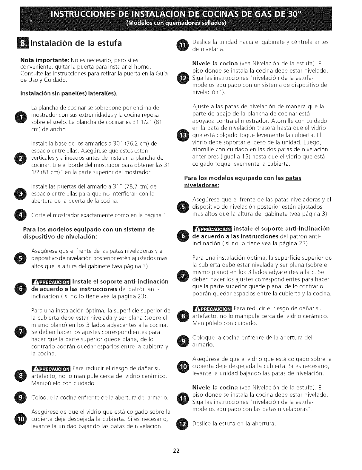
(Figura 8).
3. Verifique si la cocina esta nivelada colocando
una parrilla en el centro del homo y poniendo
un nivel sobre esta (Figura 9).
4. Mida dos veces con el nivel en posiciOn
diagonal en una direcciOn y luego en otra.
Nivele la cocina si es necesario ajustando las
patas de nivelaci6n.
5. Si al cocina no se nivela, aseg0rese que el piso
este nivelado.
Para los modeJos equipado con las
patas niveladoras,
Nivele la esufa y ajuste la altura de la estufa
antes de instalarla en la abertura.
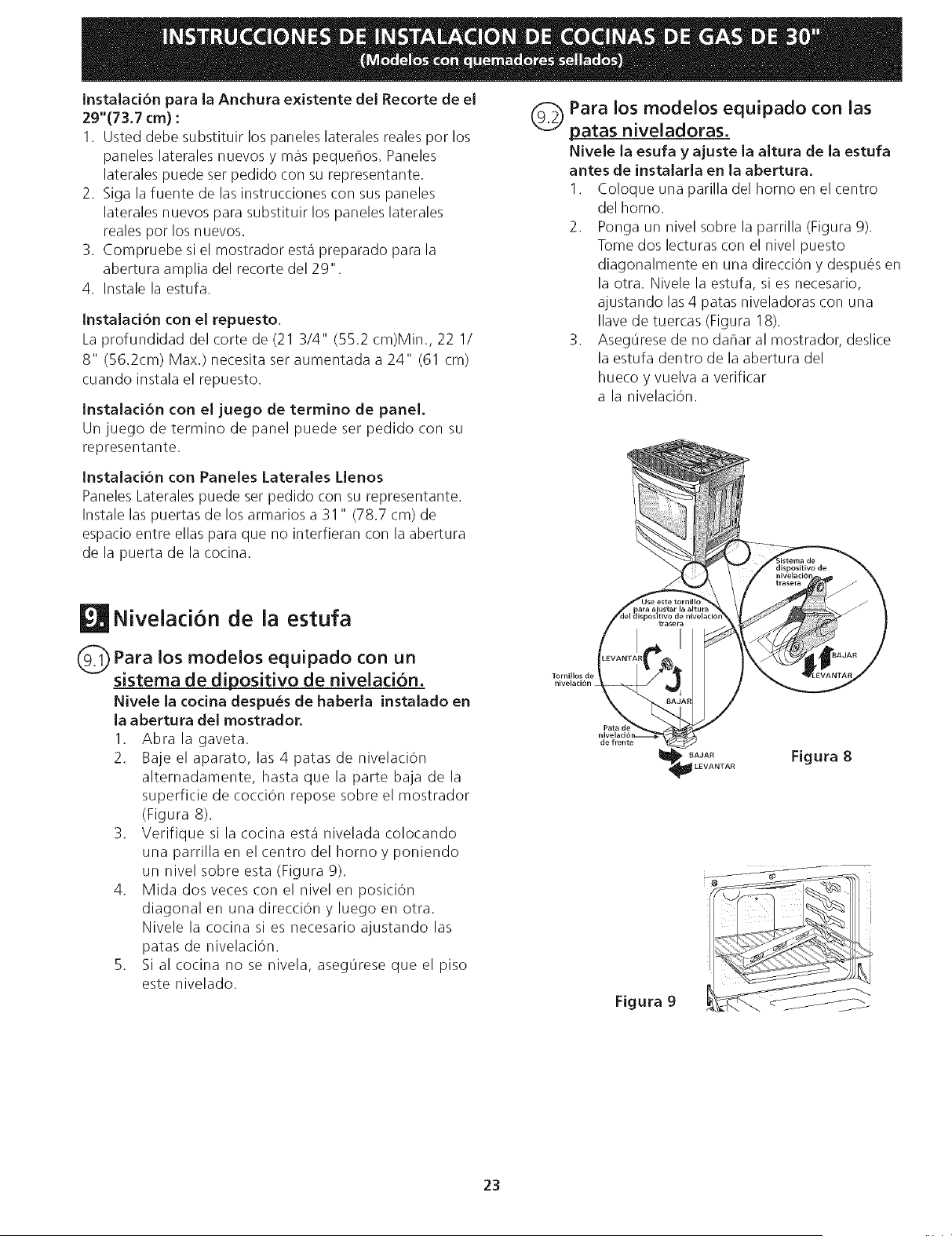
1. Coloque una parilla del homo en el ¢entro
del horno.
2. Ponga un nivel sobre la parrilla (Figura 9).
Tome dos lecturas con el nivel puesto
diagonalmente en una direcciOn y despues en
la otra. Nivele la estufa, si es necesario,
ajustando las 4 patas niveladoras con una
Ilave de tuercas (Figura 18).
3. Aseg0rese de no daflar al mostrador, deslice
la estufa dentro de la abertura del
hueco y vuelva a verificar
a la nivelaciOn.
Tornillos de
nivelaci6n
de frente
Figura 8
Figura 9
23
Instalacion de Accesorio
Decorativo Trasero (si se requiere)
1. Desconecte la alimentacion del aparato.
2. Aseg0rese de que el aparato est_ nivelado.
3. Tire la cocina hacia usted.
4. Tome la distancia entre el piso y la superficie debajo
del marco de la parte superior de la cocina.
5. Marque la distancia sobre la pared donde instalara el
accesorio decorativo.
6. Dibuje una linea.
7. Coloque la parte superior del accesorio decorativo
debajo de esa linea.
8. Utilizando los tornillos provistos con este juego, fije el
accesorio decorativo a la pared.
9. Deslice el aparato hacia atras hasta que quede en la
posiciOn deseada y encienda la alimentaciOn (la parte
inferior de la parte superior de la cocina debe estar
ubicada sobre el accesorio decorativo).
Figura 10
Comprobacion del funcionamiento
Consulte el Manual del Usuario incluido con la estufa
para instrucciones de operaci6n y instrucciones para el
cuidado y limpieza de su estufa.
No toque Ioselementoso quemadores. Pueden estar
bastante calientes para causar quemaduras.
Quite todo el embalaje de la unidad antes de
comprobarla.
11.1 Instala las Bases y las tapas de los
Quemadores
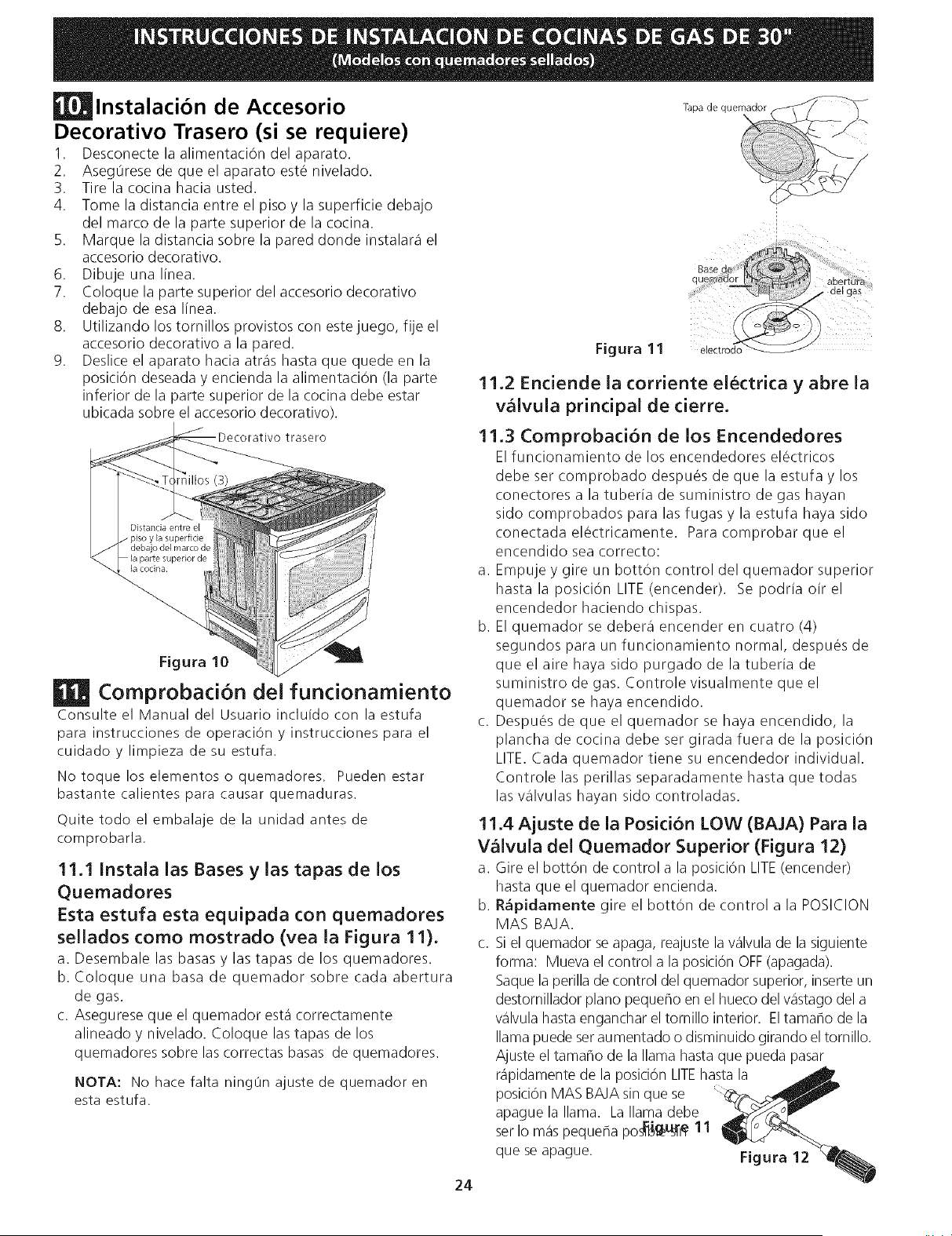
Esta estufa esta equipada con quemadores
seiJados como mostrado (vea la Figura 11).
a. Desembale las basas y las tapas de los quemadores.
b. Coloque una basa de quemador sobre cada abertura
de gas.
c. Asegurese que el quemador esta correctamente
alineado y nivelado. Coloque las tapas de los
quemadores sobre las correctas basas de quemadores.
NOTA: No hate falta ningun ajuste de quemador en
esta estufa.
Base (
Figura 11
electrodo
11.2 Enciende la corriente ei_ctrica y abre la
wilvuia principal de cierre.
11.3 Comprobacion de los Encendedores
Elfuncionamiento de los encendedores el6ctricos
debe ser comprobado despues de que la estufa y los
conectores a la tuberia de suministro de gas hayan
sido comprobados para las fugas y la estufa haya sido
conectadael_ctricamente. Paracomprobarqueel
encendido sea correcto:
a. Empuje y gire un bottOn control del quemador superior
hastala posici6n LITE(encender). Sepodriaoirel
encendedor haciendo chispas.
b. El quemador se debera encender en cuatro (4)
segundos para un funcionamiento normal, despues de
que el aire haya sido purgado de la tuberia de
suministro de gas. Controle visualmente que el
quemador se haya encendido.
c. Despu6s de que el quemador se haya encendido, la
plancha de cocina debe ser girada fuera de la posiciOn
LITE.Cada quemador tiene su encendedor individual.
Controle las perillas separadamente hasta que todas
las valvulas hayan sido controladas.
11.4 Ajuste de la Posicion LOW (BAJA) Para la
Valvula del Quemador Superior (Figura 12)
a. Gire el bottOn de control a la posici6n LITE(encender)
hasta que el quemador encienda.
b. R_pidamente gire el bottOn de control a la POSICION
MAS BAJA.
c. Si el quemador se apaga, reajuste la %lvula de la siguiente
forma: Mueva el control a la posici6n OFF(apagada).
Saque la perilla de control del quemador superior, inserte un
destornillador piano pequeflo en el hueco del vastago del a
%lvula hasta enganchar el tornillo interior. El tamaflo de la
llama puede seraumentado o disminuido girando el tornillo.
Ajuste el tamaho de la llama hasta que pueda pasar
r@idamente de la posici6n LITEhasta la
posici6n MAS BAJAsin que se
apague la llama. La llama debe
ser Io mas pequefla pos_g_L_i'#11
que se @ague. Figura 12
24
11.50perad6n de Quemadores del Homo y
Ajustes de Homo
11.5.1 Quemadore de ignic6n electrica
La operaci6n de los encendores el_ctricos debe de ser
revisada despQesde que la cocina y los conectores de la linea
de suministro haya sido cuidadosamente revisada para
descartar fugas y que la cocina haya sido conectada a la
coriente el@ctrica.
Elquemador del homo esta equipado con un sistema de
control electrico asi como un encendedor de quemador de
homo el_ctrico. Si su modelo esta equipado con un
quemador de asado central superior, tambi_n contara con un
encendedor de quemador el_ctrico. Estossistemas de control
no requieren ajustes. Cuando el homo esta configurado para
operar, la coriente fluira hacia el encendedor y tendra un
resplandor de manera similar a una bombilla de luz. Cuando
el encendedor a alcanzado una temperatura suficiente para
encender el gas, la valvula del homo controlada
el@ctricamentese abrira y el fuego aparecera en el quemador
del homo. hay un lapso de tiempo de 30 a 60 segundos
depues de que el termostato se enciende y antes de que la
llama aparezca en el quemador del horno. Cuando el homo
alcanza la configuraci6n del dial, el encendedor
resplandeciente se apagar& la llama del quemador
desaparecera por 20 a 30 segundos despues de que el
encendedor se apage. Para mantener qualquier temperatura
de homo dada, este ciclo continuara tanto como el dial (o
visualizador) est_ configurado para operar.
Despues de retirar todos los materiales del empaque y la
literatura del homo:
a) Fijeel homo en HORNEAR(BAKE)a 300°F. Vea la guia de
Usoy Cuidado para conocer las instrucciones de
funcionamiento.
b) En60 segundos el quemador del homo se encender&
Reviseque exista un fuego adecuado, y permita que el
quemador cumpla su ciclo una vez. Gire los controladores
hacia off (APAGADO).
c) Si su modelo esta equipado con un asador central superior,
fije el homo en ASAR.Vea la Guia de Uso y Cuidado para
conocer lasinstrucciones de funcionamento.
d) En60 segundos el quemador de asar debe de encenderse.
Revisesi exista una llama adecuada. Gire los controles
hacia off (APAGADO).
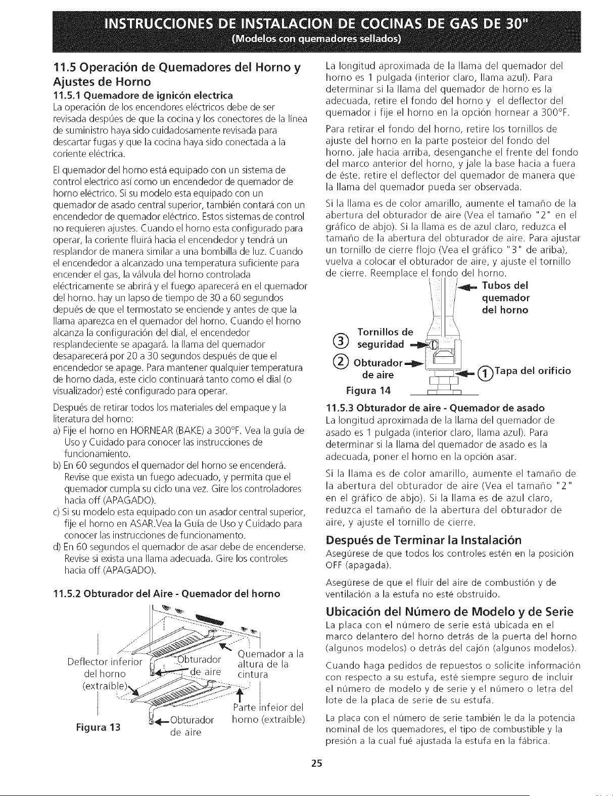
11.5.20bturador deJ Aire - Quernador deJ homo
././""
Quemador a la
Deflector inferior )turador altura de la
del homo aire cintura
(extraible), Parte nfeior del
_1.-Obturador homo (extraible)
Figura 13 de aire
La Iongitud aproximada de la llama del quemador del
homo es 1 pulgada (interior claro, llama azul). Para
determinar si la llama del quemador de homo es la
adecuada, retire elfondodelhomoy el deflectordel
quemador i fije el homo en la opci6n hornear a 300%.
Para retirar el fondo del homo, retire los tornillos de
ajuste del homo en la parte posteior del fondo del
horno, jale hacia arriba, desenganche el frente del fondo
del marco anterior del homo, y jale la base hacia a fuera
de 6ste. retire el deflector del quemador de manera que
la llama del quemador pueda ser observada.
Si la llama es de color amarillo, aumente el tamaflo de la
abertura del obturador de aire (Vea el tamaFlo "2" en el
grafico de abjo). Si la llama es de azul claro, reduzca el
tamaFlo de la abertura del obturador de aire. Para ajustar
un tornillo de cierre flojo (Vea el grafico "3" de ariba),
vuelva a colocar el obturador de aire, y ajuste el tornillo
de cierre. Reemplace el fondo del horno.
Tubos del
quemador
del homo
Tornillos de
seguridad ,-_
@ Obturador -,_
de aire Tapa del orificio
Figura 14
11.5.30bturador de aire - Quernador de asado
La Iongitud aproximada de la llama del quemador de
asado es I pulgada (interior claro, llama azul). Para
determinar si la llama del quemador de asado es la
adecuada, poner el homo en la opciOn asar.
Si la llama es de color amarillo, aumente el tamaF/o de
la abertura del obturador de aire (Vea el tamaF/o "2"
en el grafico de abjo). Si la llama es de azul claro,
reduzca el tamaho de la abertura del obturador de
aire, y ajuste el tornillo de cierre.
Despues de Terminar la Instalacion
Asegurese de que todos los controles esten en la position
OFF(apagada).
Asegurese de que el fluir del aire de combusti6n y de
ventilaci6n a la estufa no este obstruido.
Ubicad6n del NQmero de Modelo y de Serie
La plata con el numero de serie est,1 ubicada en el
marco delantero del homo detr_is de la puerta del homo
(algunos modelos) o detr_is del caj6n (algunos modelos).
Cuando haga pedidos de repuestos o solicite informaci6n
con respecto a su estufa, este siempre seguro de incluir
el numero de modelo y de serie y el nOmero o letra del
Iote de la plata de serie de su estufa.
La placa con el numero de serie tambien le da la potencia
nominal de los quemadores, el tipo de combustible y la
presi6n a la cual fue ajustada la estufa en la f_ibrica.
25
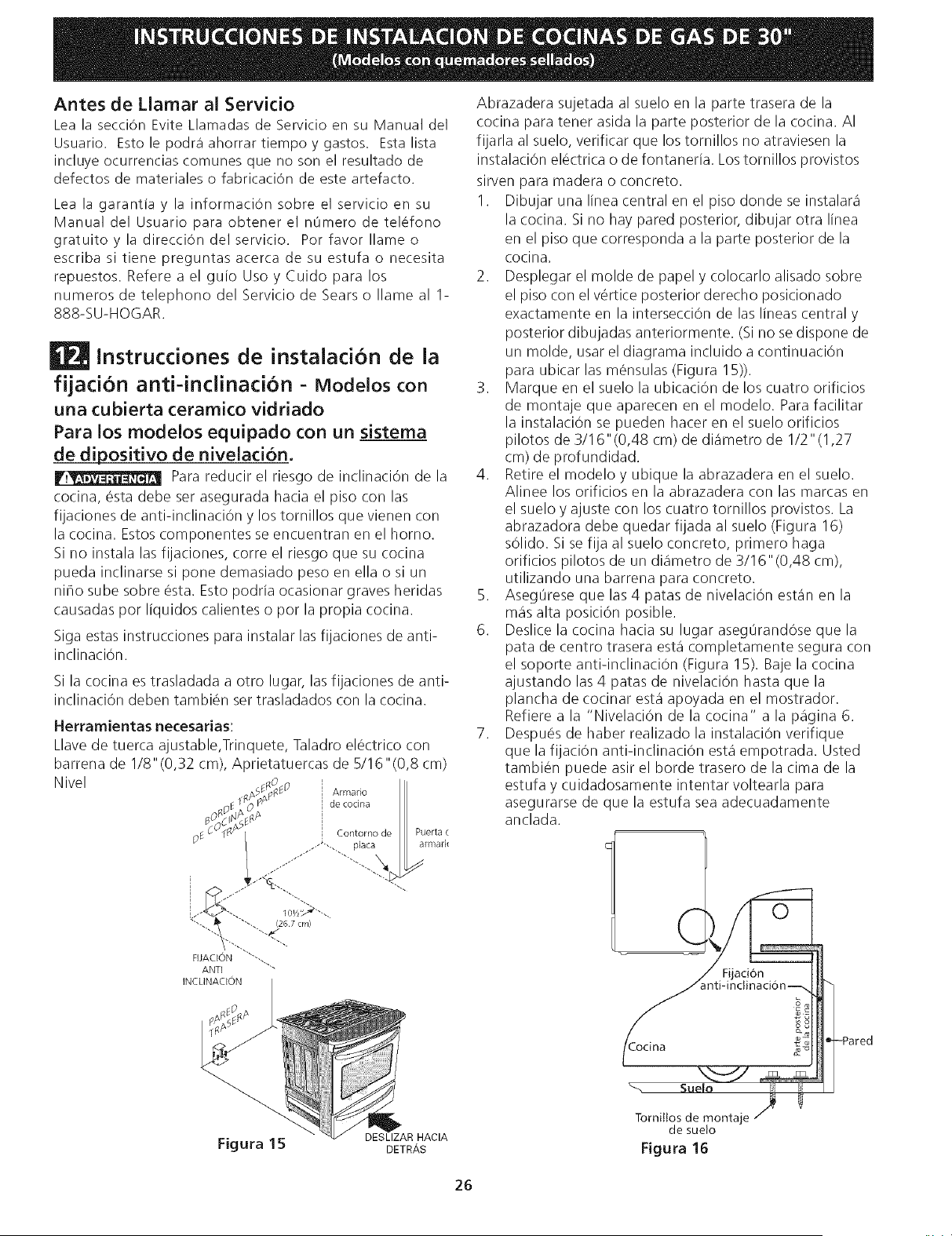
Antes de Llamar al Servicio
Lea la secci6n Evite Llamadas de Servicio en su Manual del
Usuario. Esto le podr_ ahorrar tiempo y gastos. Esta lista
incluye ocurrencias comunes que no son el resultado de
defectos de materiales o fabricaciOn de este artefacto.
Lea la garantia y la informaciOn sobre el servicio en su
Manual del Usuario para obtener el nOmero de telefono
gratuitoyla direcci6n delservicio. Por favor Ilameo
escriba si tiene preguntas acerca de su estufa o necesita
repuestos. Refere a el guio Uso y Cuido para los
numeros de telephono del Servicio de Sears o Ilame al 1-
888-SU-HOGAR.
Instrucciones de instalacion de la
fijacion anti-inclinaci6n - Modelos con
una cubierta ceramico vidriado
Para los modelos equipado con un sistema
de dipositivo de nivelaci6n.
Para reducir el riesgo de inclinaci6n de la
cocina, _sta debe ser asegurada hacia el piso con las
fijaciones de anti-inclinaci6n y los tornillos que vienen con
la cocina. Estos componentes se encuentran en el homo.
Si no instala las fijaciones, corre el riesgo que su cocina
pueda inclinarse si pone demasiado peso en ella o si un
niho sube sobre _sta. Esto podria ocasionar graves heridas
causadas por liquidos calientes o por la propia cocina.
Siga estas instrucciones para instalar las fijaciones de anti-
inclinaci6n.
Si la cocina es trasladada a otro lugar, las fijaciones de anti-
inclinaci6n deben tambi_n ser trasladados con la cocina.
Herramientas necesarias:
Llave de tuerca ajustable,Trinquete, Taladro el_ctrico con
barrena de I/8"(0,32 cm), Aprietatuercas de 5/16 "(0,8 cm)
Nivel
Abrazadera sujetada al suelo en la parte trasera de la
cocina para tener asida la parte posterior de la cocina. AI
fijarla al suelo, verificar que los tornillos no atraviesen la
instalaciOn el_ctrica o de fontaneria. Los tornillos provistos
sirven para madera o concreto.
1. Dibujar una linea central en el piso donde se instalara
la cocina. Si no hay pared posterior, dibujar otra linea
en el piso que corresponda a la parte posterior de la
cocina.
2. Desplegar el molde de papel y colocarlo alisado sobre
el piso con el vertice posterior derecho posicionado
exactamente en la intersecciOn de las lineas central y
posterior dibujadas anteriormente. (Si no se dispone de
un molde, usar el diagrama incluido a continuaciOn
para ubicar las m_nsulas (Figura 15)).
3. Marque en el suelo la ubicaciOn de los cuatro orificios
de montaje que aparecen en el modelo. Para facilitar
la instalaciOn se pueden hacer en el suelo orificios
pilotos de 3/16"(0,48 cm) de diametro de 1/2"(1,27
cm) de profundidad.
4. Retire el modelo y ubique la abrazadera en el suelo.
Alinee los orificios en la abrazadera con las marcas en
el suelo y ajuste con los cuatro tornillos provistos. La
abrazadora debe quedar fijada al suelo (Figura 16)
sOlido. Si se fija al suelo concreto, primero haga
orificios pilotos de un diametro de 3/16" (0,48 cm),
utilizando una barrena para concreto.
5. AsegOrese que las 4 patas de nivelaci6n estan en la
mas alta posici6n posible.
6. Deslice la cocina hacia su lugar aseg0randOse que la
pata de centro trasera esta completamente segura con
el soporte anti-inclinaciOn (Figura 15). Baje la cocina
ajustando las 4 patas de nivelaciOn hasta que la
plancha de cocinar esta apoyada en el mostrador.
Refiere a la "Nivelaci6n de la cocina" a la pagina 6.
7. Despu_s de haber realizado la instalaci6n verifique
que la fijaciOn anti-inclinaciOn esta empotrada. Usted
tambi_n puede asir el horde trasero de la cima de la
estufa y cuidadosamente intentar voltearla para
asegurarse de que la estufa sea adecuadamente
anclada.
acton
Figura 15
DESLIZAR HACIA
DETRAS
Tornittosde montaje
de sue!o
Figura 16
26
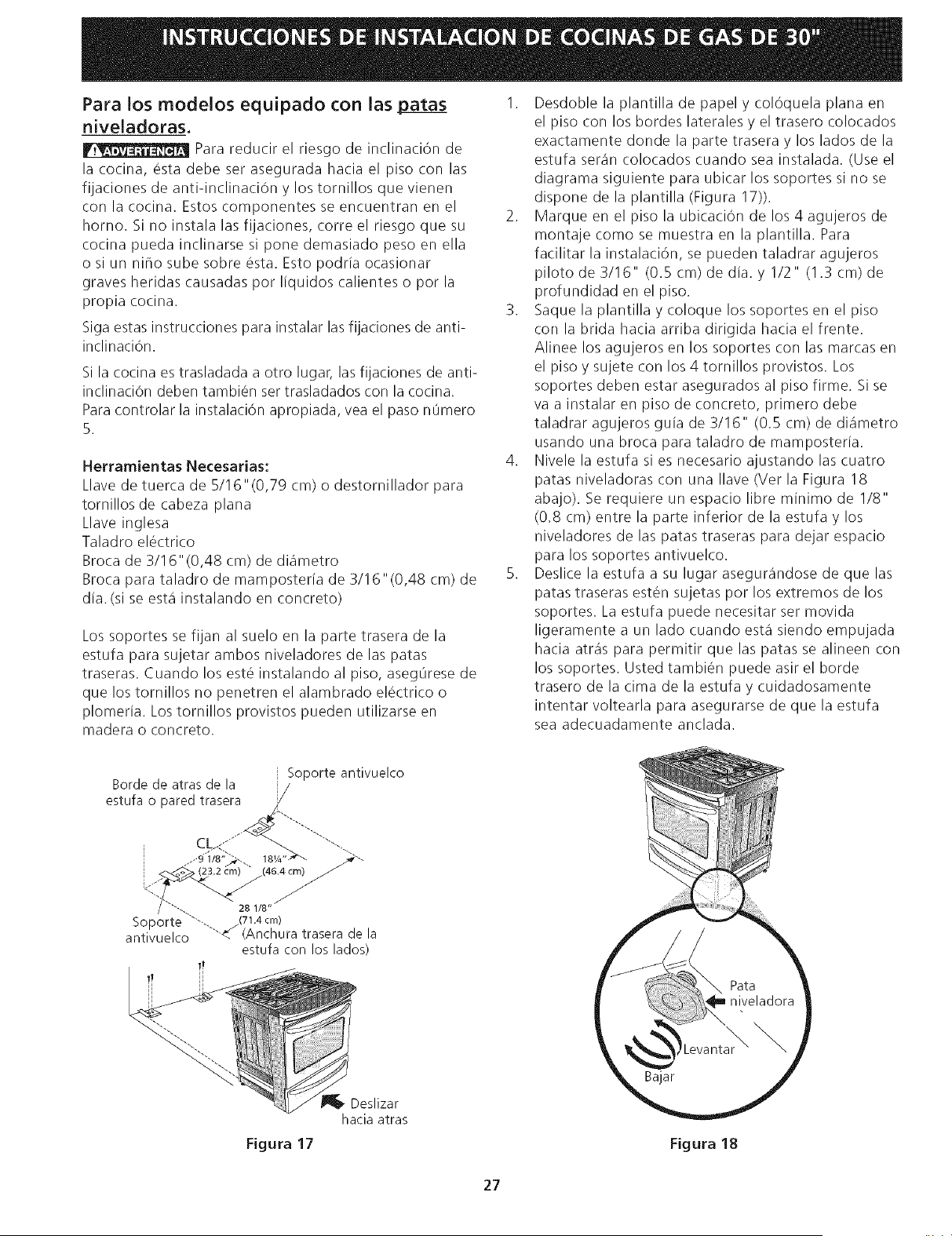
Para los modelos equJpado con las patas
niveladoras.
Para reducir el riesgo de inclinaci6n de
la cocina, 6sta debe ser asegurada hacia el piso con las
fijaciones de anti-inclinaci6n y los tornillos que vienen
con la cocina. Estos componentes se encuentran en el
homo. Si no instala las fijaciones, corre el riesgo que su
cocina pueda inclinarse si pone demasiado peso en ella
o si un niflo sube sobre _sta. Esto podria ocasionar
graves heridas causadas por liquidos calientes o por la
propia cocina.
Siga estas instrucciones para instalar las fijaciones de anti-
inclinaciOn.
Si la cocina es trasladada a otro lugar, las fijaciones de anti-
inclinaciOn deben tambi6n ser trasladados con la cocina.
Para controlar la instalaci6n apropiada, vea el paso nOmero
5.
Herramientas Necesarias:
Llave de tuerca de 5/16"(0,79 cm) o destornillador para
tornillos de cabeza plana
Llave inglesa
Taladro el6ctrico
Broca de 3/16"(0,48 cm) de diametro
Broca para taladro de mamposteria de 3/16"(0,48 cm) de
dia. (si se esta instalando en concreto)
Los soportes se fijan al suelo en la parte trasera de la
estufa para sujetar ambos niveladores de las patas
traseras. Cuando los est6 instalando al piso, asegOrese de
que los tornillos no penetren el alambrado el6ctrico o
plomeria. Los tornillos provistos pueden utilizarse en
madera o concreto.
1. Desdoble la plantilla de papel y col6quela plana en
el piso con los hordes laterales y el trasero colocados
exactamente donde la parte trasera y los lados de la
estufa sere_ncolocados cuando sea instalada. (Use el
diagrama siguiente para ubicar los soportes si no se
dispone de la plantilla (Figura 17)).
2. Marque en el piso la ubicaci6n de los 4 agujeros de
montaje como se muestra en la plantilla. Para
facilitar la instalaci6n, se pueden taladrar agujeros
piloto de 3/16" (0.5 cm) de dia. y I/2" (1.3 cm) de
profundidad en el piso.
3. Saque la plantilla y coloque los soportes en el piso
con la brida hacia arriba dirigida hacia el frente.
Alinee los agujeros en los soportes con las marcas en
el piso y sujete con los 4 tornillos provistos. Los
soportes deben estar asegurados al piso firme. Si se
va a instalar en piso de concreto, primero debe
taladrar agujeros guia de 3/16" (0.5 cm) de diametro
usando una broca para taladro de mamposteria.
4. Nivele la estufa si es necesario ajustando las cuatro
patas niveladoras con una Ilave (Ver la Figura 18
abajo). Se requiere un espacio libre minimo de I/8"
(0.8 cm) entre la parte inferior de la estufa y los
niveladores de las patas traseras para dejar espacio
para los soportes antivuelco.
5. Deslice la estufa a su lugar asegurandose de que las
patas traseras est6n sujetas por los extremos de los
soportes. La estufa puede necesitar ser movida
ligeramente a un lado cuando esta siendo empujada
hacia atre_spara permitir que las patas se alineen con
los soportes. Usted tambi6n puede asir el horde
trasero de la cima de la estufa y cuidadosamente
intentar voltearla para asegurarse de que la estufa
sea adecuadamente anclada.
Borde de atras de la
estufa o pared trasera
Soporte antivuelco
Figura 17 Figura 18
27

NOTAS :
28
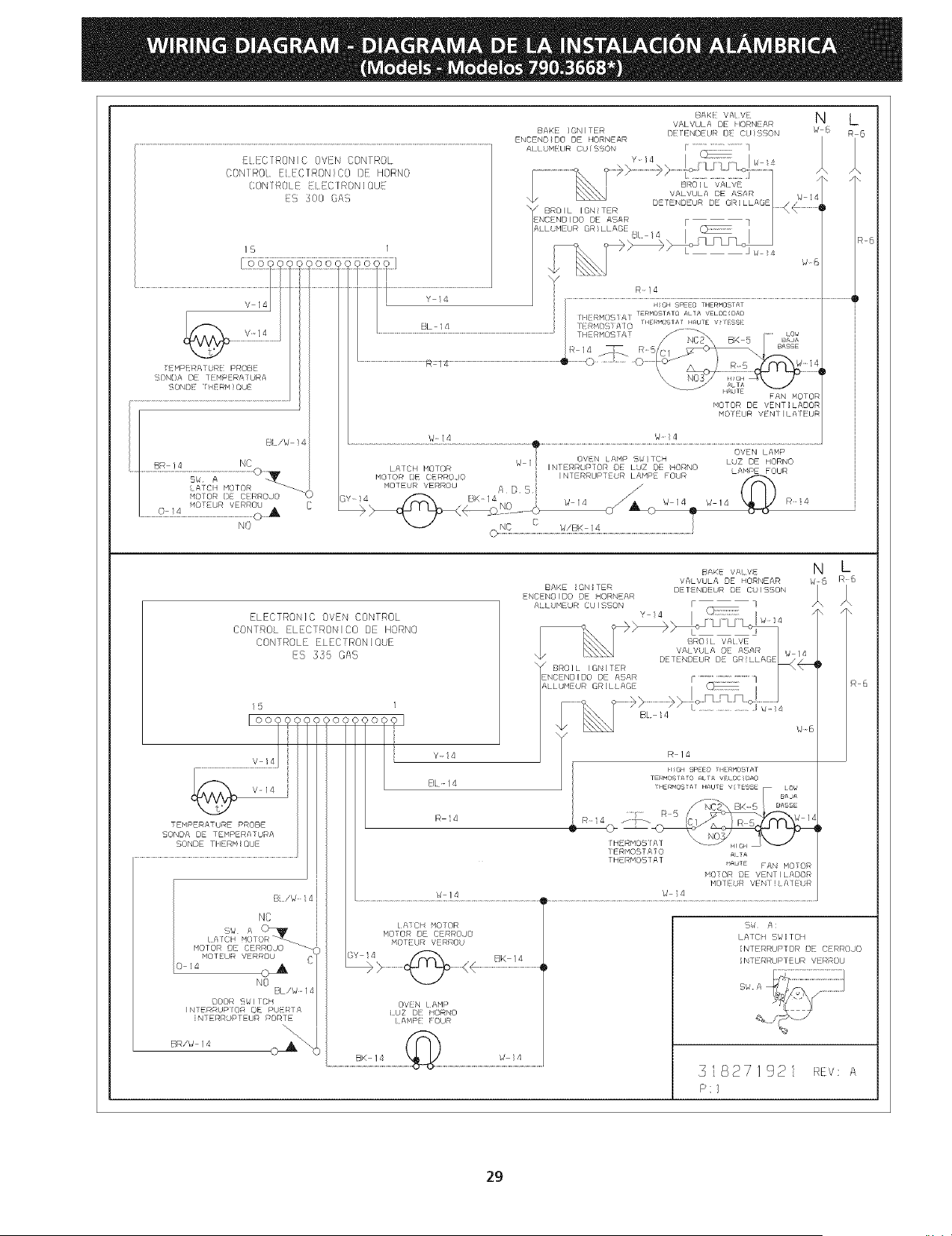
E[ECIRONIC OVEN CONTROL
CONIR01. E{EC/RONIC0 DE HORN()
CON1R0/E ELEC1RON]OUE
ES 300 GAS
15 I
v 14
EMPERA] RE RROB
BON}A DE 1EMPERAYURA
B/_/g !4
BR /4 NC
C
N0
BAKE IGNITER
ENCEND}DO DE HORNEAR
\_ BROIL [GN!TER
ENCEND}DO DE ASAR
:_AKVAtV N L
VALVULA DE HORNEAR
DF IENOFL)R [) (_JI iBON /,J (/ F/ 6
/\
/. /\
W 14
DEIENDEUR DE OR]LLAGE _ _,
r I
R-}4
C
ELECTRON]C OVEN CONTROL
CONTROL ELECTRONIC0 DE HORN0
CONTROLE ELECTRONi0UE
ES 355 GAS
15
I ooo?<
V 14
_ V 14 )
TEMPERATURE PROBE
SONDA DE TEMPERATURA
SONDE TIIERN!©UE
MOTOR DE CERROJO _}
MOTEUR VERROU (}
0 14 {_
NO
BL/WI4
DOOR B_lfE_/
JNTERRUPIOR DE PUERF£
iNTERRUPTEUR PORTE
BR/W 14
Y-!4
BL-14
R _4
w 14
LAICH MOTOR
MOTOR DE CERROJO
MOTEUR VERROU
OVEN LAMP
iUZ DE HORNO
IAMPE FOUR
BAKE IGNITER
ENCENBIDO DE HORNEAR
SAKE VALVE
VALVULA DE HORNEAR
DETENDEUR DE CU!SBON
N L
TT
W 14
/ DETENDEUR DE GRILLAGE¸
BROIL'_ITER _
_LLUMEURGRILLAoEZNCENOIOODE ASAR i _i/F ............................ 7
, IL t ..........................
W-6
R 14
NGH SPEED HERMDSTAT
TERM©SIA_© ALTA VELOCIOA{9
E_MOS _A HAU_E V _ESSE LO_
8AJA
[HERMOBFA] _ _ 6,/ t
IE_MOS A 0 m_A
THERMOSTAT _AUTE FAN MOTOR
MOTOR DE VENT I LADOR
MOlE R VEN} ]LA]E R
W 14
BW A:
LATCH BW]TCN
INTERRUPTOR BE CERROJO
INTERRUPTEUR VERROU
318271921 REv: A
P:/
R 6
2g
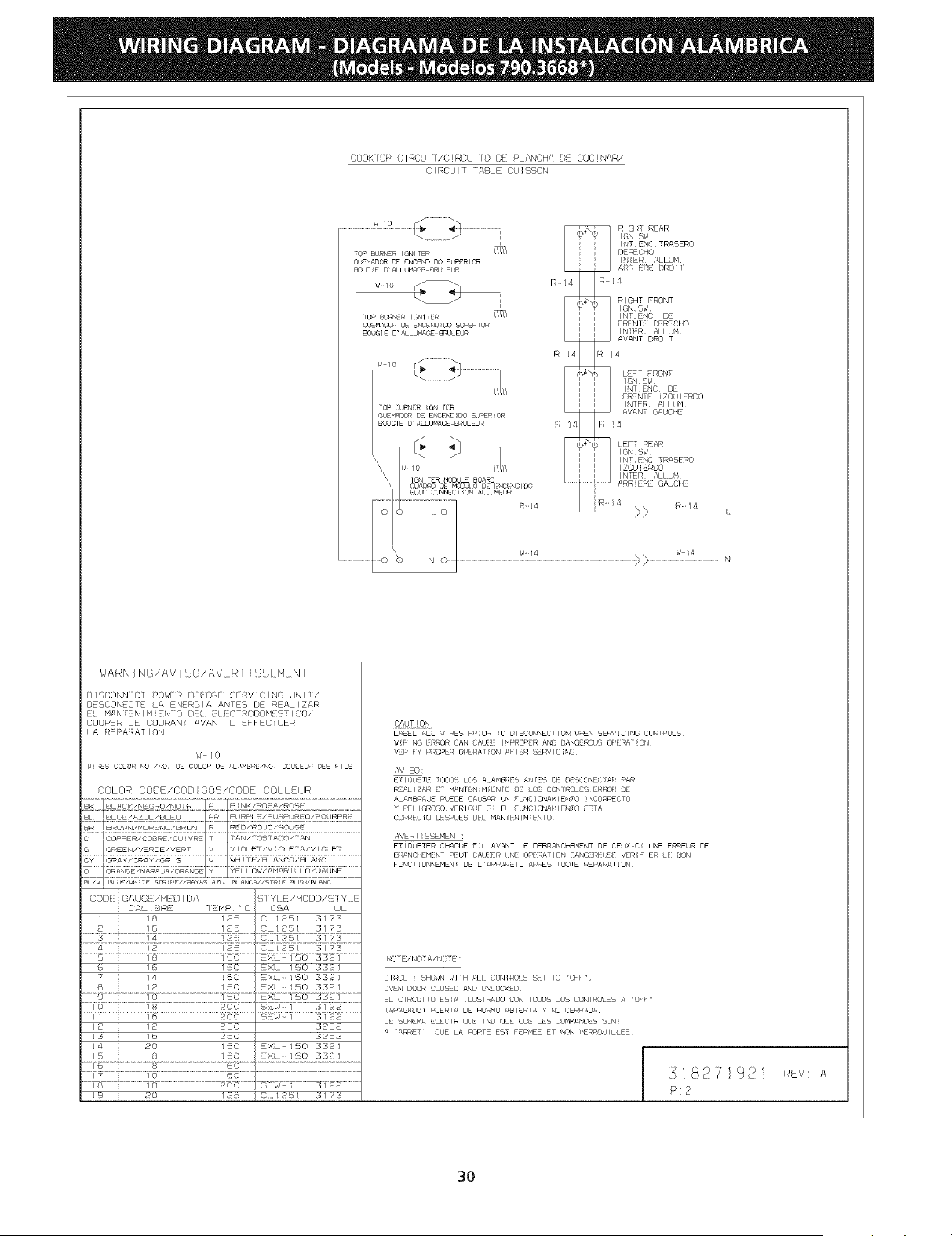
COOK OP C I _CUIT/C RCUI YO DE / LANCHA ) COC)NAR/
CIRCU T TABLE CU]SSON
........................................i _ _ nm,TREAR
m_/ / NT ENC TRASERO
OUENADOR DE NC_NOIO0 Sb_ZRIOR NTER ALLUM
BOJGE D'AII J_A_SEC_RL EUR ARR HI [)R0I I
OL_.AX_n0 NCNUO0sL/-mor_ / bE:O0
R 14 R 4
,,,o ............................
_ 1 _ _) LEFT FRONT
............ I ION SW
_, I ITENC D
I FRENE ZQU ] ERDO
OUFMAD_ D_ E_rCE_ DO SdPER)OR I
EX,'dGI8 ©" ALLUMAGE BRULEUR _- 14 _l_ ! ,I
% [ ( [EFT REAR
I I NT E_XC, TRASERO
I ZOU E_DO
INTER ALLUH
IMq_T' R MUDJLE BUf/RD l J ARR r::_u_'f f
CJA[]RO [_f M0[_) 0 ) :NC NDI)O L C u _ E
......................o% =o_......................................................................................................................_>...................._:?_.................._,
WARNING/AV SO/AVER }SSEHENT
) I SCONN[ C 1 POWER B[i: O:/ _RV 1( [NG UN [ /
DESCONECTE LA ENERGIA ANTES DE REALIZAR
i M/\N_EN I H I ENI0 DE I E(}TROBOH:SI I CO/
COUPER LE COURANT AVANT D'EFFECTUER
A R[ PARA T I ON
W /0
w RES COLOR NO /NO DE COLOR DE ALAMBRE/NO COULEU DES F LS
COLOR CODE/COD GOB/CODE COULEUR
? I 4 } 150 EX.- 150
8 ] 2 } 150 EXL- 150
iiiiiqi:::::iIiiiiiiiiii!@:::::::iiiii:::::iiii!iiiiiZ:_::_i::::::::::
I 0 / 1 ¢_ 200 {%'_ ] .............
11 1 R_ (51 g_FP .....
12 12 250
is I 16 250
/ 4 20 150 I !XL / SO
15 _ 8 150 i EX 11_0
......i£ ]...................._o................................PO0 [s_wcf ...........
3321
3321
332i ..............
3iNs .............
3252
3252
3321
-:! _1 ]...........
3122 ............
3 ! Z3
@6Y!_LON:
LABEL ALL llRES PRIOR TO DISCONNECTION WHEN SERV[C]NG CONTROLS
/J lING E/IOR CAN CAU_ I N:ROM:R AND DANG :_OUS OPRAT ON
VRIFY PRO,:'ER OPERAT ON A 1 Eq SERV It" NG
AVISO:
E IOU]TE 0[:)0 _ I0:_ AL AM_:/E% ANI[_; DE {}[SCRNI C AR PAR
¢;AL ZAR ET MANIEN!H ENIO DE LOS COND#OLE'3 ER!OR DE
ALAMBRAJE PUEDE CAUSAR ON FUNC]ONAHIENTO )NCO_RECTO
Y PEL}GROSO VERIC/dE S EL FUNC]ONAMIENTO ESTA
CC/ RICTO I_}PUES I)IL MAN NIM INIO
AVERT SSEHENT :
ETJQUETER CHAOUE FIL AVANT LE DEBRANCHENENT DE CEUX C UNE ERR_OR DE
BI:ANC I:M NT _UI CALJI_ _ J_: 0:> :RA ION DAN[£:£R Uq VIA FIE_ IE: f:SON
FONCT)ONNEMENT DE L'APPAREIL APRES TOJTE REPARAT[ON
NOTE/NC)TA/NO I E :
CIRCUIT 5HORN _]TH ALL CONTROLS SET TO "OFF"
OVEN DOOR CLOSED AND b%_OCKED
EL CIRCUITO ESTA [LUSTRADO CON TODOS LOS CONTROLES A "OFF"
(APAGADO} PUERTA DE HC_O ABIERTA Y NO CER4ADA
LE SCHEMA ELECTRIQUE INDIQUE Qbr LES COMMANDES SONT
A "ARRET" ,QUE LA PORTE EST FERdEE ET NON VERROUILLEE
,;182Z1921 _v: A
P:2
B0
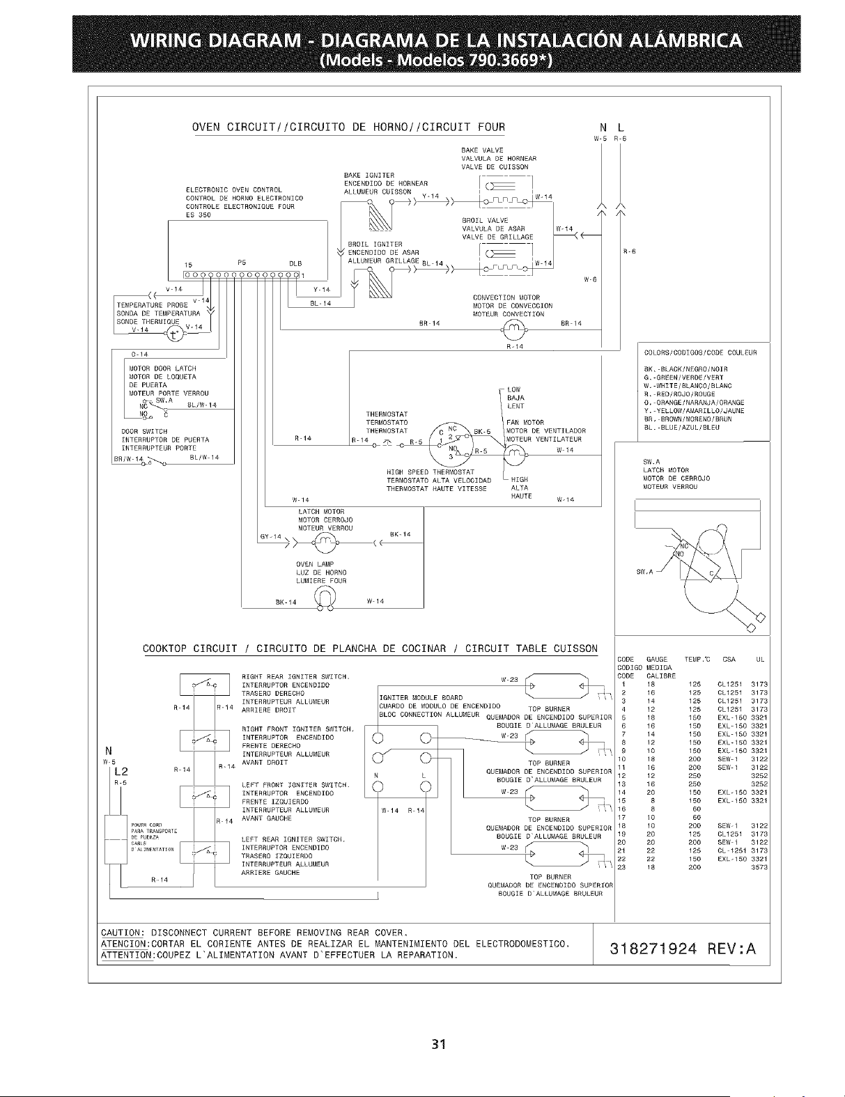
OVEN CIRCUIT//CIRCUITO DE HORNO//CIRCUIT FOUR N L
W-5 R-6
BAKE VALVE
VALVULA DE HORNEAR
VALVE DE CUISSON
BAKE IGNITER
ENCENOIO0 DE HORNEAR [ (_
ELECTRONIC OVEN CONTROL ALLUMEUR CUISSON Y 14 I I
CONTROL DE HORNO ELECIRONICO O _/,/> '''_ \\/c_FLFIS__/_ _
EsOONTROLE355ELEOTRONIOOEFDOR GROI MALV "' M,A
VALVULA DE ASAR W-14
VALVE DE GRILLAGE _
BRDIL IGNITER
_: ENCENDIDO DE ASAR [ _ 1
ALLUMEUR GRILLAGE BL 14 I IW.14
15 P5 DLB ,_/ _M _ _>_OF F F _ W-6
_ DDNVECTION MOTOR
MOTOR DE CONVECCION
MOTEUR CONVECTION
BR 14 _ BR 14
R-14
R-6
0-14
MOTOR DOOR LATCH
MOTOR DE LOQUETA
DE PUERTA
MOTEUR PORTE VERRDU
N_"Q W'A GL/W- 14
DOOR SWITCH
INTERRUPTOR DE FUERTA
INTERRUPTEUR PORTE
R-14
W-14
LATCH MOTOR
MOTOR CERROJO
MOTEUR VERROM
OVEN LAMP
LUZ DE HORNO
LUMIERE FOUR
LOW
BAJA
lENT
THERMOSTAT
TERMOSTATO FAN MOTOR
THERMOSTAT RK-5 MOTOR DE VENTILADOR
- _ . MOTEUR VENTI LATEUR
HIGH SPEED THERMOSTAT
TERMOSTATD ALTA VELOCIDAD HIGH
THERMDSTAT HAUTE VlTESSE ALTA
HAUTE W- 14
BK-14 W 14
COOKTOP CIRCUIT / CIRCUITO DE PLANCHA DE COCINAR / CIRCUIT TABLE CUISSON
RIGHT REAR IGNITER SWITCH.
INTERRUPTOR ENCENDIDO
TRASERD DERECHO
INTERRUPTEUN ALLGMEUR
ARRIERE DROIT
RIGHT FRONT IGNITER SWITCH,
[NTERRUPTDR ENCENDIDD
FREMTE DERECRO
INTERRUPTEUR ALLUMEUR
AVANT DROIT
LEFT FRONT IGNITER SWITCH.
INTERRUPTOR ENOENDIDO
FRENTE IZQUIERDD
INTERRGPTEDR ALLUMEUR
AVANT GAUCHE
LEFT REAR IGNITER SWITCH,
INTERRUFTOR ENCENDIDO
TRASERO IZQUIENDO
INTERRUPTEUR ALLMMEUR
ARRIERE GAUCHE
W_23 [_<__
IGNITER MODULE BOARD __ I
CUARDO DE MODULO DE ENCENDIDO TOP BURNER
BLOC CONNECTEON ALLUMEUR QUEMAOOR DE ENOEMOZO0 SUPERIOR
BDUGIE D ALLUMAGE BRULEUR
TOP BURNER
QUEMADDR DE ENCENDIDD SUPERIDR
L BOUGIE O'ALLUMAGE BNGLEUR
W-14 R 14
TOP BURNER
QUEMADOR DE ENOENDIDO SUPERIOR
BOUGIE D ALLUMAGE MRULEUR
W-23 _ _'1
TOP BURNER
QUEMAOOR DE EMCENOIO0 SUPERIOR
BOUGIE D'ALLUMAGE BRULEUR
COLORS/CODIGOS/CODE COULEUR
BK,-BLACK/MEGRO/NOIR
G,-GNEEM/VERDE/VERT
W, WHITE/BLANOO/BLANC
R. RED/ROJD/ROUGE
O,-ORANGE/NARANJA/ORANGE
Y.-YELLOW/AMARILLO/JAUNE
DR, BROWN/MOREND/BRUN
BL. BLUE/AZUL/BLEU
SW,A
LATCH MOTOR
MOTOR DE CERROJO
MDTEUR VERROU
I I
I
CODE GAUGE TEMP,"C CSA UL
COOIGO MEDIDA
CODE CALIBRE
1 18 125 CL1251 3173
2 16 125 CL1251 3173
3 14 125 CL1251 3173
4 12 125 CL1231 3173
5 18 155 EXL-150 3321
6 16 150 EXL-150 3321
7 14 150 EXL-15D 3321
8 12 150 EXL-150 3321
9 10 150 EXL-150 3321
10 18 200 SEW-1 3122
11 16 205 SEW-1 3122
12 12 250 3252
13 16 25D 3252
14 20 15D EXL-150 3321
15 8 15D EXL-150 3321
16 8 60
17 10 60
18 10 200 SEW-I 3122
19 20 125 CL1251 3173
20 20 200 SEW 1 3122
21 22 125 CL-1251 3173
22 22 155 EXL-150 3321
23 18 200 3573
CAUTION: DISCONNECT CURRENT BEFORE REMOVING REAR COVER,
ATENCION:CORTAR EL CORIENTE ANTES DE REALIZAR EL MANTENIMIENTO DEL ELECTRODOMESTtCO.
ATTENTION:COUPEZ L'ALIMENTATZON AVANT D'EFFECTUER LA REPARATION.
318271924 REV:A
31
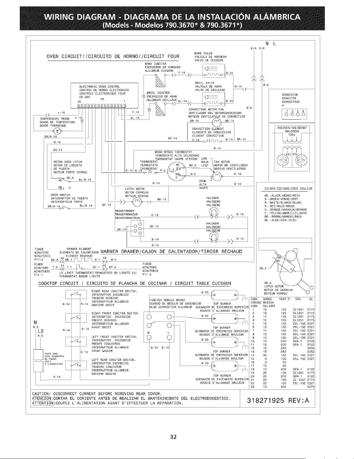
OVEN CIRCUIT//CIRCUITO DE HORNO/!CIRCUIT FOUR
15
v_14Ii °°°
I TENRERAPORE ROOEv4,
hB°B°wOETEMPERATMOAjSONDET ME
BR/W-14
0-14
MR-14
MOTOR DOOR LATCH
MOTOR DE LOQUETA
DE PUERTA
MOTEUR PORTE VERROU
c SW.A
NC_ eL/W - 14
N_ C
DOOR SWITCH
INTERRUPTOR DE PUERTA
INTERRUPTEUR PORTE
BR/W-14 _ BL/W 14
sc
TIMER WARNER ELEMEN_
MINUTERO
ELECTRONIC OVEN CONTROL
CONTROL DE HORNO ELECTRONIC0
CONTROLE ELECTRONIQUE FOUR
ES 565
P5
1
oooooooooo_
I
Y-14
BL 14
N L
W_5 R-6
GY-14
BAKE VALVE
VALVMLA DE HORMEAR
VALVE DE CUISSON
BAKE IGNITER
ENCENDIDO DE HORNEAR I
ALLUM[UR CUISSON Y-14 \ I mLm F_ IW14
20 LIA VEAsARWI"
VALVE DE GRILLAGE _
BROIL IGNITER I
_ ENCENOIDO DE ASAR
ALLUMEUR GRILLAGE BL-14 ' 'W 14
4,_\ / CONVECTION MOTOR FAN W-6
BR-14 c_q_ c 8R 14
CONVECTION ELEMENT
ELEMENTO DE CONVECCION
ELEMENT CONVECTION
MR-14 0 14 _F_ _ 0-14 BR 14
R 14
HIGH SPEED THERMOSTAT
TERMOSTATO ALTA VELOCIOAD
THERMOSTAT HAUTE VITESSE LOW
THERMOSTAT BAJA FAN MOTOR
TERMOSTATO SN-5 LENT MOTOR DE VENTILADOR
THERMOSTAT -- MOTEUR VENTILATEUR
R-14 R 14_ T,
W-14 ALTA W-14
LATCH MOTOR HAUTE
MOTOR CERROJO
NOTEUR VERROU
_._ BK 14 HALOGEN
_ RALOGENO
HALOGENE
'RWNBFORNER <__>
rRANSFORMADOR W-14 W-14
:RANSPORM_
_i HALOGEN
@0 BK-14 HALOGENO
BK-14 RALOGENE
W-14
ELEMENTODECWLENTADOBWARMER DRAWER/CAJON DE CALENTADOR/TIROIR RECHAUD
W-5
TIMER
M,NO,ERoTIMER NINOTERO
MINUTERIE LO LIMIT THERNOSTAT/TERNOSTATO DE LIMITO LO/ MINUTERIE
Pl1-1 Pll-2
THERNOSTAT MASSE LINITE
COOKTOP CIRCUIT / CIRCUITO DE PLANCHA DE COCINAR / CIRCUIT TABLE CUISSON
RIGHT REAR IGNITER SWITCH,
INTERRUPTOR ENCENDIDO
TRASERO DERECHO
INTERRUPTEUR ALLUNEUR
ARRIERE DROIT
RIGHT FRONT IGNITER SWITCH,
INTERRUPTOR ENCENDIDO
FRENTE DERECHO
INTERRUPTEOR ALLUMEUR
AVANT DROIT
LEFT FRONT IGNITER SWITCH.
INTERRUPTOR ENOENDIDO
FRENTE IZQOIERDO
INTERRUPTEUR ALLUMEUR
AVANT GAUCHE
LEFT REAR IGNITER SWITCH,
INTERRUPTOR ENCENDIDO
TRASERO IZQUIERDO
INTERRUPTEUR ALLUMEUR
ARRIERE GAUCHE
©
W-BS ....
IGNITER MODULE BOARD
CUARDO DE MODULO DE ENCENDIDO TOP BURNER
BLOC CONNECTION ALLUMEUR QUEMADOR DE ENCENDIDO SUPERIOR
BOUGIE D'ALLUMAGE BRMLEUR
TOP BURNER
QUEMADOR DE ENCENDIDO SUPERIOR
BOOGIE D'ALLUMAGE BRULEUR
W 23 I _1
W 14 R-14
TOP BURNER
QUEMADOR DE ENCENDIDO SUPERIOR
BOUGIE D'ALLUMAGE BRULEUR
/ "..
TOP BURNER
QUENADOR DE ENCENDIDO SUPERIOR
BOOGIE D'ALLUMAGE BRULEUR
N
W_5
L2 R-14
R-5
PAPA TRa SPORTE
DE FU_E_ZA
CA_a_
D ALIt_[NTA_ION
R-14
/k /\
\ /\
R-6
CONNECTOR
CONECTOR
CONNECTEUR
A
d&&& I
HALOGEN/HALOGENO/
HALOGENE
COLORS/CODIGOS/CODE COULEUR
BK,-BLACK/NEGRO/NOIR
G.-GREEN/VEROE/VERT
W,-WHITE/BLANCO/BLANC
R.-RED/ROJO/ROUGE
O. ORANGE/NARANJA/ORANGE
Y. YELLOW/AMARILLO/JAUNE
BR.-BROWN/MORENO/BRUN
BL,_BLUE/AZUL/BLEU
SW.A
MOTEUR VERROU
CODE GAUGE TEMP.'C CSA UL
CODIGO MEDIDA
CODE CALIBRE
1 18 125 CL1251 3173
2 16 125 CL1251 3173
3 14 125 CL1251 3173
4 12 125 0L1251 3173
5 18 150 EXL-150 3321
6 16 150 EXL-150 3321
7 14 150 EXL 150 3321
8 12 150 EXL 150 3321
9 10 150 EXL*150 3321
10 18 200 SEW I 3122
11 16 200 SEW-1 3122
12 12 250 3252
13 16 250 3252
14 20 150 EXL-150 3321
15 8 150 EXLI50 3321
16 8 60
17 10 60
18 10 200 SEW-I 3122
19 20 125 CL1251 3173
20 20 200 SEW-1 3122
21 22 125 CL-125_ 3173
22 22 150 EXL 150 3321
23 18 200 3573
CAUTION: DISCONNECT CURRENT BEFORE REMOVING REAR COVER.
ATENCION:CORTAR EL CORIENTE ANTES DE REALIZAR EL MANTENIMIENTO DEL ELECTRODOMESTICO,
ATTENTION:COUPEZ L'ALIMENTATION AVANT D'EFFECTUER LA REPARATION.
318271925 REV'A
32