Loading ...
Loading ...
Loading ...
035-16329-002 Rev. B (0304)
THE FURNACE CONTROLS
AND THEIR FUNCTION
1.
=ON-OFF-FAN" switchturns
electrical power to the furnace
on and off. The switch must be
set in the "ON" position for the
furnace to operate. To run the
blower continuously without
heating, set the switch to
"FAN".
2. Limit Control - This furnace is
protected by two (2) high tem-
perature limit switches. The
lower limit switch is an auto-
matic reset type.
IMPORTANT - The upper limit 1.
switch near left side of blower is a
manual reset type limit switch. If 2.
burner does not function, turn sys-
tem switch to =OFF"and push reset 3.
button in center of limit switch.
4.
3.
Gas Valve - The gas valve is
100% shut-offtype and willfail
safe iffor some reasonthe gas
isturned offor the pilotgoes
out. It isalso ofthe step-open
type whichmeans theyopento
a lowfire positionand affer a
few seconds step-opento high
fire.
4.
warm weather and heat from
the pilot. This isnormal opera-
tionas long as there ispower
to thefurnace and the ON-
OFF-FAN switch isat the "ON"
position.IF blower operationis
not desired,the ON-OFF-FAN
switchmay be set in the"OFF"
positionto cutthe electrical
powerto the furnace.
INSTRUCTIONS FOR
AUTOMATIC IGNITION
MODELS
LIGHTING INSTRUCTIONS
5.
6.
Fan Switch - This fanswitch is 7.
a temperature sensingdevice
that turnson the blower when
sufficientheat has builtup
withinthe furnace, It alsoturns
the bloweroffwhen thefurnace
has cooled down sufficiently
after burnershut-off. Inwarm 8,
weather,there isa possibilityof
the blower comingon periodi- 9,
celly or operatingcontinuously
due toa heat buildupwithinthe 10.
furnace bya combinationof
STOP! Read the safety infor-
mation
Set the thermostatto the low-
est setting,or =OFF'.
Turn off all electdc power to the
furnace.
This appliance does not have a
pilot. It is equipped with an igni-
tion device which automatically
lights the burner. Do not try to
light the burner by hand.
Remove upper door panel.
Move gas valve control switch
to =OFF".See Figure 2.
Wait five (5) minutes to clear
out any gas. Then smell for
gas, including near the floor. If
you smell gas, STOP! Follow
Step 3, in the Safety Informa-
tion above. If you don't smell
gas, go to the next step.
Move gas control switch to
"ON".
Replace upper door panel.
Turn on allelectricpowertothe
furnace.
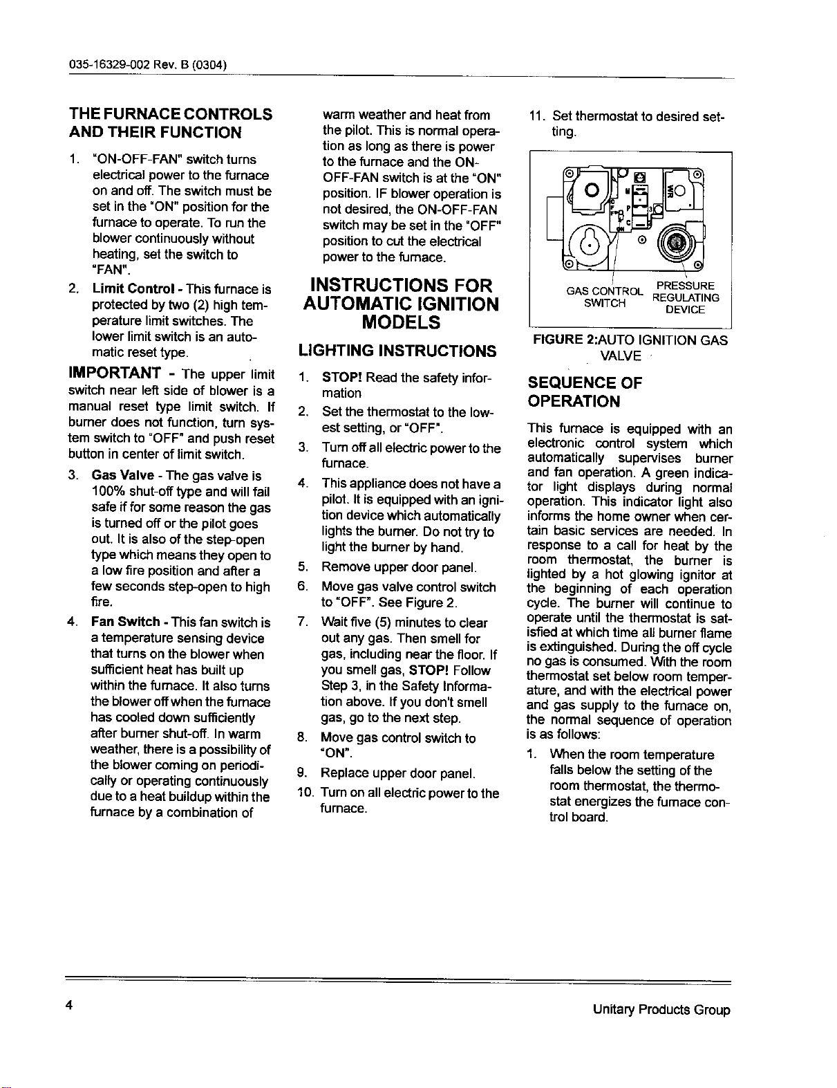
11. Set thermostat to desired set-
ting.
GAS CONTROL PRESSURE
SWITCH REGULATING
DEVICE
FIGURE 2:AUTO IGNITION GAS
VALVE
SEQUENCE OF
OPERATION
This fumace is equipped with an
electronic control system which
automatically supervises burner
and fan operation. A green indica-
tor light displays dudng normal
operation. This indicator light also
informsthe home owner when cer-
tain basic services are needed. In
response to a cell for heat by the
room thermostat, the burner is
lighted by a hot glowing ignitor at
the beginning of each operation
cycle. The burner will continue to
operate untilthe thermostat is sat-
isfiedat whichtime all burnerflame
isextinguished.Duringthe offcycle
no gas isconsumed. Withthe room
thermostatset below roomtemper-
ature, and with the electdcel power
and gas supply to the fumace on,
the normal sequence of operation
is as follows:
1.
When the roomtemperature
falls belowthe settingofthe
roomthermostat,the thermo-
stat energizes thefurnace con-
trolboard.
4 Unitary Products Group
Loading ...
Loading ...
Loading ...