Owners
Manual
FOR POTABLEWATER
HEATING ONLY
NOT SUITABLEFOR
SPACEHEATING
Model No.
153.320390HT 30 Gal.
153.320391HT 30 Gal.
153.320490HT 40 Gal.
153.320491HT 40 Gal.
153.320590HT 50 Gal.
153.320591 HT 50 Gal.
153.320690HT 66 Gal.
153.3206911HT 66 Gal.
,53.32oo,o,HT/
153.32089I/H!r
Caution:
Read and Follow
All Safety Rules and
Operating Instructions
Before First Use of
This Product.
Savethis Hanualfor Future Reference.
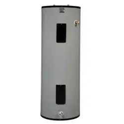
POWER MISER TM 12+
LECTRIC
WATER HEATER
• Safety Instructions
• Installation
• Operation
• Care and Maintenance
• Troubleshooting
• Parts List
GAHA certificaUonappliesto all residential electric water heaterswith
capacitiesof 20 to 120Gallons.Input rating of 12Kw or lessat a voltage
no greaterthan 250 V.
_I_WARNING I
READ THE GENERAL SAFETY SECTION BEGINNING ON INSIDE COVER
AND THEN THIS ENTIRE MANUAL BEFORE INSTALLING OR OPERAT-
ING THIS WATER HEATER.
Sears, Roebuck and Co., Hoffman Estates, IL 60179 U.S.A.
Safety Precautions
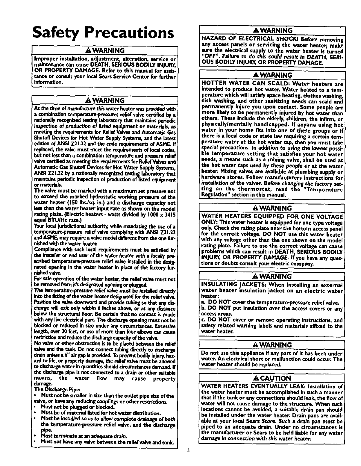
AWARNING
Improper installation, adjustment, alteration, service or
maintenancecancauseDEATH, SERIOUSBODILY INJUR_,
OR PROPERTY DAMAGE. Refer to this manual for assis-
tunce or consultyour localSearsServiceCenter for further
information.
A WARNING
At the b.'_. of manufacturethis waterbeaterwasprovldedwi_
a €.ombmationtempemtu.r_pressures reliefvalvecertifiedbya
nationallyrecognized testing laboratorythat maintains periedic
inspection of production of listedequipmentor materials, as
meetingthe requirementsfor ReliefValvesandAutomaticGas
ShutoffDevicesfor Hot Water SupplySystems,and the latest
ed'_onofANSI 7.21.22andthecoderequirementsofASME.If
replaced,the valvemust.meetthe mqulrementsoflocalcedes,
but notlessthanacombinationtemperatureandpressurerelief
valvecertifiedasmeetingtherequirementsfor ReliefValvesand
AutomaticGasShutoffDevicesfor Hot Water SupplySystems,
ANSI Z21.22bya nationallyrecognizedtestinglaboratorythat
rmuntalasperiodicinspec_onofproductionoflistedequipment
or material_
The valvemustbemarkedwith a maximum setpressurenot
to exceedthe marked hydrostaticworkingpressure of the
water heater (150 IbsJsq.in.) and a dischargecapacitynot
lessthan tile water heater inputrate asshownon the n_odel
rating plate.(Electricheaters- watts dividedby 1000x 3415
equal BTU/Hr. rate.)
Yourlocaljurisdictionalauthority,whilemandatingthe useof a
temperature-pressurereliefvalvecomplyingwith ANSI Z21.22
andASME,mayrequire avalvemodeldifferentfrom theonefur-
nishedwiththewaterheater,
Compliancewith suchlocalrequirementsmust besatisfiedby
the installeror enduserof tile waterbeater with a Ira:allypre-
scribedtemperature-pressurereliefvalveinstalledin the desig-
nated openingin the water heater in placeof the factoryfur-
nisbedva/se.
Forsafeoperatianofthe waterheater,the reliefvalvemustnot
beremovedfrom it'sdesignatedopeningorplugge(L
.The. temperature-pressurere|iefv_e mat beinstalleddirectly
mto thefiUingoftbewaterheaterdesignatedferthereliefvalve.
Positionthe valvedownwardandprovidetubing sothat anydis-
cbe_,ewill exit onlywithin6 inchesabove,or at anydistance
belowthe structuralfloor.Be certainthat no contactismade
withanyliveelectricalpart.Thedischa_eopeningmust not be
blockedor reducedin sizeunderanycircumstance_Excessive
length,over30 feet,or useofmore than fourelbowscancause
restrictionandreducethe dischargecapacityof thevalve.
No valveor otherobstructionistu beplacedbetweenthe relief
valveandthe tank.Do notconnecttubing directlyto discharge
drainunlessa6"airgapisprovided.Topreventbodilyinjury,haz-
ardto life,or propertydamage,the reliefvalvemustbeallowed
to d'.l_,bargewater!nquantitiesshoulddrcumstancasdemand.If
the d_chargepipemnotconnectedto a drainor othersuitable
means, the water flow may cause property
damage.
The DischargePipe:
• Mustnot be smallerinsizethan the outlotpipesizeof the
valve,or haveanyreducingcouplingsor otherrestrictfon_
• Mustnot be pluggedor blocked.
• Mustbe ofmaterial listedfor hot waterdistribution.
• Mustbe instal/edsoaste al/ow completedreinageofheth
the temperature-pressurereliefvalve,and the discharge
pipe.
• Must terminateat anaslequatedroin.
• Mustnot haveanyvalvebotweenthe relief valveandtank.
I
I AWARNING I
HAZARD OF ELECTRICAL SHOCK! Before removing{
any access panels or servicing the water heater, make I
sure the e!ectncal supply to the water heater is turned
"OFF". Fmlure to do this could result in DEATH, SERi- {
OUS BODILY INJURY,OR PROPERTY DAMAGE. I
_,WARNING
HOTTER WATER CAN SCALD: Water heaters are
intended to produce hot water. Water heated to a tem-
perature whichwill satisfyspaceheating, clothes washing,
dish washing, and other sanitlzmg needs can scald and
permanently injure you upon contact. Some people are
more likely to be permanently injured by hot wafer than
others. These includethe elderly, children, the infirm, or
physically/mentally handicapped. If anyone using hot
water in your home fits into one of these groups or if
there isa localcode or state law requiring a certain tem-
perature water at the hot water tap, then you must take
specmiprecautions,in addition to usingthe lowest possi-
ble temperature setting that satisfies your hot water
needs, a means such as a mixing valve, shall be used at
the hot water taps usedby these people or at the water
heater. Mixing valvesare availableat plumbingsupplyor
hardware stores. Follow manufacturers instructions for
insta/latlon of the valves.Before changingthe factory set-
ting on the thermostat, read the "Temperature
Regulation"sectionin this manual.
&WARNING
WATER HEATERS EQUIPPED FOR ONE VOLTAGE
ONLY: Thiswater heater isequippedfor one type voltage
only.Checkthe ratmg plate near the bottom accesspanel
for the correct voltage. DO NOT use this water heater
with anyvoltage other than the one shownon the model
rating plate. Failure to usethe correct voltage can cause
problemswhich can result in DEATH, SERIOUS BODILY
INJUR_,OR PROPERTY DAMAGE. If you haveany ques-
tions or doubtsconsultyour electric company.
A, WARNING
INSULATING JACKETS: When installing an external
water heater insulation jacket on an electric water
heater:
a. DO NOT coverthe temperature-pressure relief valve.
b. DO NOT put insulation over the accesscoversor any
access areas.
c. DO NOT cover or remove operating instroctions,and
safety related warning labelsand materials affixed to the
water heater.
AWARNING
Do not usethis applianceif any part of it hasbeen under
water. An electrical short or malfunction couldoccur.The
water heater shouldbe replaced.
• ,CAUTION
WATER HEATERS EVENTUALLY LEAK: Installation of
the water heater must be accomplishedin sucha manner
that ifthe tank or anyconnectionsshouldleak, the flowof
water will not causedamage to the structure. When such
locationscannot be avoided, a suitable drain pan should
be installedunder the water heater. Drain pansare avail-
able at your local Sears Store. Such a droJnpan must be
piped to an adequate drain. Under no circumstances is
the manufacturer or Searsto be held liable for any water
damage in connectionwith this water heater.
2
Table of Contents
Safety Precautions ...............................................................................................................................................2
Table of Contents ..........................................................................................................................3
Introduction ...............................................................................................................................................................4
Product
_pecltlcatlons ..................................................................................................................................4
Preparing for the New Installation .............................................................................................4
Materials and Basic Tools Needed ...............................................................................................5
Materials Needed ...................................................................................................................................................................... 5
BasicTools ................................................................................................................................................................................ 5
Installation Instructions ........................................................................................................................6-15
Removing the Old Water Heater ............................................................................................................................................... 6
Factsto Consider About the Location ....................................................................................................................................... 7
Factsto Consider About the Convertible Lower Hement .......................................................................................................... 7
Water Piping ............................................................................................................................................................................. 8
Temperature-Pressure ReliefValve........................................................................................................... :................................. 9
Filling the Water Heater .......................................................................................................................................................... 10
Converting the Lower Element .......................................................................................................................................... 10-12
Wiring Diagrams .................................................................................................................................................................... 13
Wiring .................................................................................................................................................................................... 14
Installation Checklist .............................................................................................................................................................. 15
Service
and
Adlustment ......................................................................................................................16-20
Temperature Ragulation i. ................................................................................ 16
Thermostats ............................................................................................................................................................................ 16
Thermostat Settings ................................................................................................................................................................ 16
UpperThermostat Adjustment ............................................................................................................................................... 16
LowerThermostat Adjustment ............................................................................................................................................... 17
Temperature-Pressure RaeliefValve Operation .......................................................................................................................... 17
Draining ................................................................................................................................................................................. 17
Hement Cleaning and Replacement .................................................................................................................................. 18-20
Drain ValveWasher Replacement ........................................................................................................................................... 20
Service .................................................................................................................................................................................... 20
"" -" -"lroubleshooting Guide ........................................................................................................................21-24
Start Up Conditions ............................................................................................................................................................... 21
Thermal Expansion ............................................................................................................................................................... 21
Strange Sounds ..................................................................................................................................................................... 21
Operational Conditions ..................................................................................................................................................... 22-23
Rumbling Noise .................................................................................................................................................................... 22
High Temperature Shut Off System ...................................................................................................................................... 22
Not Enough or No Hot Water .............................................................................................................................................. 23
Water is Too Hot .................................................................................................................................................................. 23
Indicator Light...................................................................................................................................................................... 23
Leakage Checkpoints .............................................................................................................................................................. 24
Parts Order List...............................................................................................................................................26-27
Warranty ........................................................................................................................................................................2_
3
Introduction
Thank You for purchasinga Sears water heater.
Properly installed and maintained, it _ould give you years of
trou-ble free service. If you should decide that you want the new
water heater professionally installed, contact the local Sears
Service Center or any Sears store. They will arrange for prompt,
quality installation by Sears authorized contractors.
Abbreviations Found In This Instruction Manual
U.L.-Underwriters Laboratories, 333 Pfrngsten Rd.,
Northbrook, IL 60062
National ElectricalCode-This publication is available from your
local government or public library or electric company or by
writing to U.L above.
A.N.S.I.-American National Standards Institute
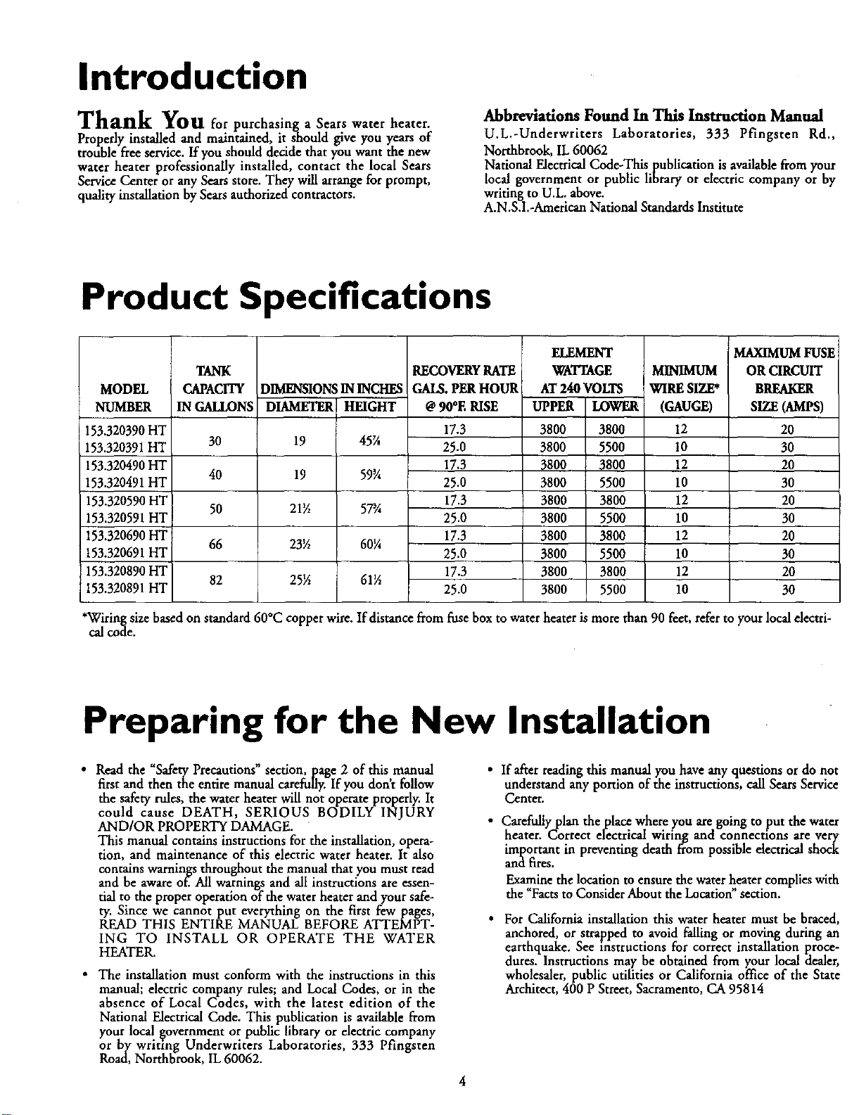
Product Specifications
MODEL
NUMBER
153.320390HT
153.320391HT
153.320490HT
153.320491HT
153.320590HT
153.320591HT
153.320690HT
153.320691HT
153.320890HT
153.320891HT
TANK
CAPACITY
IN GALLONS
30
40
50
66
82
DIMENSIONSININCHES
DIAMETER HEIGHT
19 45X
19 59¾
21_ 57¾
23_ 60¼
25½ 61½
RECOVERYRATE
GAI_. PER HOUR
@ 90*E RISE
17.3
25.0
17.3
25.0
17.3
25.0
17.3
25.0
17.3
25.0
ELEMENT
WATTAGE MINIMUM
AT 240 VOLTS !WIRE SIZE*
UPPER LOWER I (GAUGE)
3800 3800 12
3800 5500 10
3800 3800 12
3800 5500 10
3800 3800 12
3800 5500 10
3800 3800 12
3800 5500 10
3800 3800 12
3800 5500 10
MAXIMUM FUSE
ORCIRCUIT
BREAKER
SIZE (AMPS)
20
3O
20
30
20
30
20
30
20
30
*Wiringsizebasedon standard60°C copper wire.If distancefromfusebox to waterheaterismore than90 feet,referto yourlocalelectri-
calcode.
Preparing for the New Installation
• Read the "Safety Precautions" section, page 2 of this manual
first and then the entire manual carefully. If you don't follow
the safety rules, the water heater will not operate properly. It
could cause DEATH, SERIOUS BODILY INJURY
AND/OR PROPERTY DAMAGE.
This manual contains instructions for the installation, opera-
tion, and maintenance of this electric water heater. It also
contains warnings throughout the manual that you must read
and be aware of. All warnings and all instructions areessen-
tial to the proper operation of the water heater and your safe-
ty. Since we cannot put everything on the first few pages,
READ THIS ENTIRE MANUAL BEFORE ATTEMPT-
ING TO INSTALL OR OPERATE THE WATER
HEATER.
• The installation must conform with the instructions in this
manual; electric company rules; and Local Codes, or in the
absence of Local Codes, with the latest edition of the
National Electrical Code. This publication is available from
your local government or public library or electric company
or by writ]ng Underwriters Laboratories, 333 Pfingsren
Road, Northbmok, IL 60062.
• If after reading this manual you have any questions or do not
understand any portion of the instructions, call Sears Service
Center.
• Carefully plan the place where you are going to put the water
heater. Correct electrical wiring and connections are very
important in preventing death from possible electrical shock
and fires.
Examine the location to ensure the water heater complies with
the 'Facts to Consider About the Location"sect'on.
• For California installation this water heater must be braced,
anchored, or strapped to avoid falling or moving during an
earthquake. See instructions for correct installation proce-
dures. Instructions may be obtained from your local dealer,
wholesaler, public utilities or California office of the State
Architect, 400 P Street, Sacramento, CA 95814
Materials and Basic Tools Needed
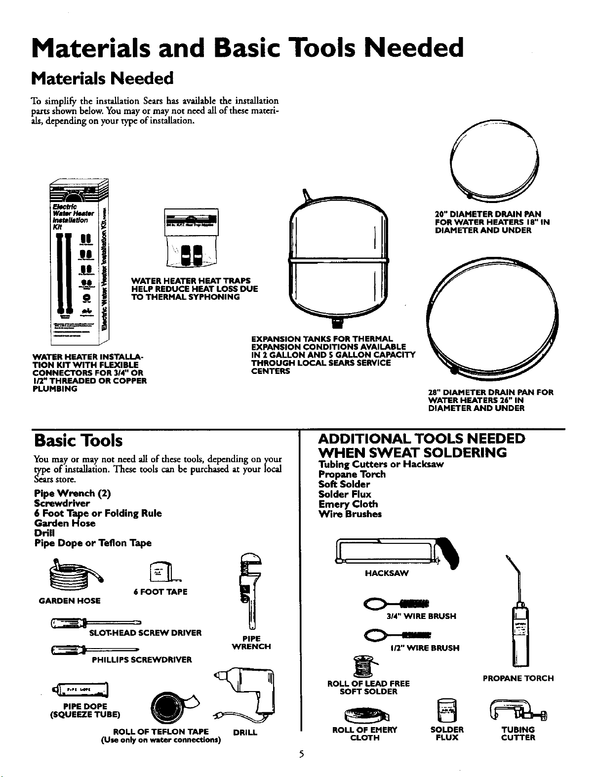
Materials Needed
To simplify the installation Sears has available the installation
parts sEown below. You may ormay not need all of these materi-
als, depending on your type of installation.
WaDr HNter
Ins_llatlon
Kit
_lJ_i
e_a_:
WATER HEATER INSTALLA-
TION KIT WITH FLEXIBLE
CONNECTORS FOR 3/4" OR
I/2" THREADED OR COPPER
PLUMBING
WATER HEATER NEAT TRAPS
HELP REDUCE HEAT LOSS DUE
TO THERMAL SYPHONING
EXPANSION TANKS FOR THERMAL
EXPANSION CONDITIONS AVAILABLE
IN 2 GALLON AND S GALLON CAPACITY
THROUGH LOCAL SEARS SERVICE
CENTERS
20" DIAMETER DRAIN PAN
FOR WATER HEATERS 18" IN
DIAMETER AND UNDER
28" DIAMETER DRAIN PAN FOR
WATER HEATERS 26" IN
DIAMETER AND UNDER
Basic Tools
You may or may not need all of these tools, depending on your
type of installation. These tools can be purchased at your local
_Lr$ store.
Pipe Wrench (2)
Screwdriver
6 Foot Tape or Folding Rule
Garden Hose
Drill
Pipe Dope or Teflon Tape
t
6 FOOT TAPE
GARDEN HOSE
SLOT-HEAD SCRL_N DRIVER
PIPE
WRENCH
PHILLIPS SCREWDRIVER
PiPE DOPE
(SQUEEZE TUBE)
ROLL OF TEFLON TAPE
(Use only on water connections)
DRILL
ADDITIONAL TOOLS NEEDED
WHEN SWEAT SOLDERING
Tubing Cutters or Hacksaw
Propane Torch
Soft Solder
Solder Flux
Emery Cloth
Wire Brushes
314" WIRE BRUSH
C>----
I/2" WIRE BRUSH
PROPANE TORCH
ROLL OF LEAD FREE
SOFT SOLDER
ROLL OF EMERY SOLDER TUBING
CLOTH FLUX CUTTER
Installation Instructions
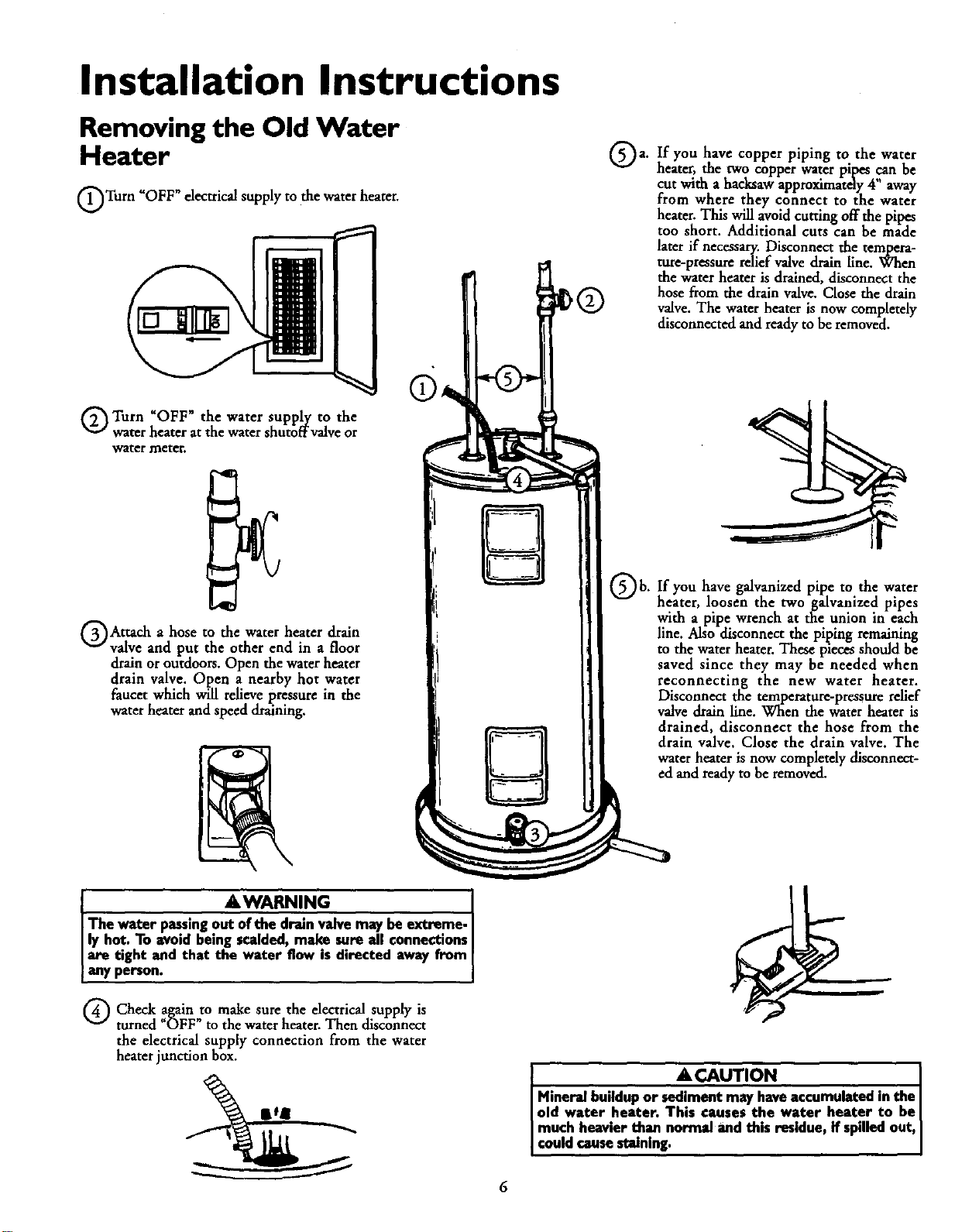
Removing the Old Water
Heater
OTurn _OFF" electrical supply to the water heater.
Q Turn "OFF" the water supply to the
water heater at the water shutoffvalve or
water meter.
QAttach a hose to the water heater drain
valve and put the other end in a floor
drain or outdoors. Open the water heater
drain valve. Open a nearby hot water
faucet which will relieve pressure in the
water heater and speed draining.
J . A WARNING [
The water pa_.ingout of the dr',anvalvemay be extreme, i
ly hot. To avoid bemg scalded, make _,.re all connecttonsI
are tight and that the water flow is dwected away from
any person.
Qa. you copper piping to water
If have
the
heater, the two copper water pipes can be
cut with a hacksaw approximatdy 4" away
from where they connect to the water
heater. This will avoid cutting off the pipes
too short. Additional cuts can be made
later if necessary. Disconnect the tempera-
ture-ptessure relief valve drain line. When
the water heater is drained, disconnect the
hose from the drain valve. Close the drain
valve. The water heater is now completely
disconnected and ready to be removed.
Qb. you galvanized pipe to water
If have the
heater, loosen the two galvanized pipes
with a pipe wrench at the union in each
line. Also disconnect the piping remaining
to the water heater. These pieces should be
saved since they may be needed when
reconnecting the new water heater.
Disconnect the temperature-pressure relief
valve drain line. When the water heater is
drained, disconnect the hose from the
drain valve. Close the drain valve. The
water heater is now completely disconnect-
and ready to be removed.
Q Check againto make sure the electrical supply is
turned "OFF" to the waterheater. Then disconnect
the electrical supply connection from the water
heater junction box.
I ACAUTION
Mineral buildupor sed!ment may haveaccumulated in the i
old water heater. This causes the water heater to be I
much heavierthan normal and this residue,if spilledout, i
couldcausestaining, i
Installation Instructions (cont'd)
Facts to Consider About the Facts to Consider About The
Location Convertible Lower Element
You should carefully choose an indoor location for the new
water heater, because the placement is a very important consid-
eration for the safety of the occupants in the building and for
the most economical use of the appliance. This water heater is
not intended for outdoor installation.
Whether replacing an old water heater or putting the water
heater in a new location, the following critical points must be
observed.
• The location selected should be indoors as close to and as
centralized with the water piping system as possible. This
water heater, as well as all water heaters, will eventually leak.
Do not install without adequate drainage provisions where
water flow will cause damage.
_CAUTION
WATER HEATERS EVENTUALLY LEAK: Installation of
the water heater must be accomplishedin sucha manner
that if the tank or anyconnectionsshouldleak, the flow of
water will not causedamage to the structure. When such
locationscannot be avoided, a suitable drain pan should
be installedunder the water heater. Drain pansare avail-
able at your local Searsstores. Sucha drain pan must be
piped to an adequate drain. Under no circumstances is
the manufacturer or Searsto be held liable for any water
damagein connectionwith this water heater.
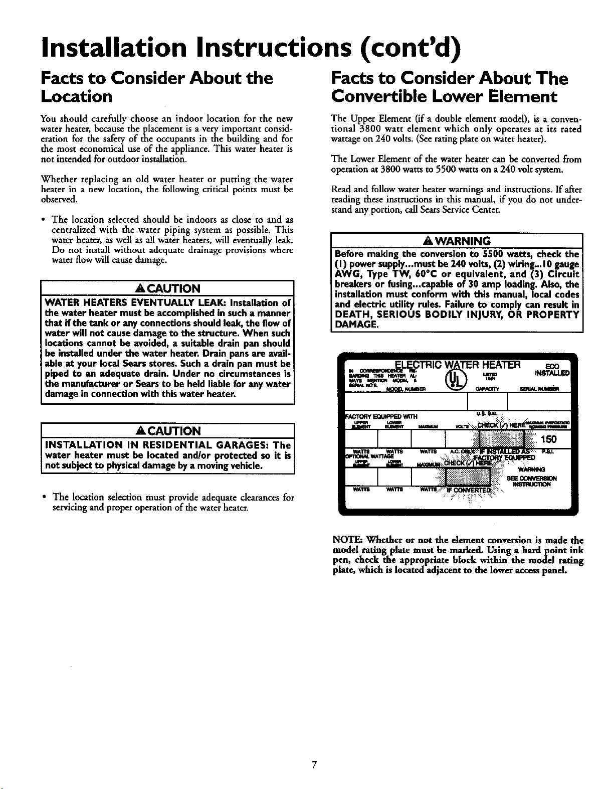
The Upper Element (if a double element model), is a conven-
tional 3800 watt element which only operates at its rated
wattage on 240 volts. (See rating plate on water heater).
The Lower Element of the water heater can be converted from
operation at 3800 watts to 5500 watts on a 240 volt system.
Read and follow water heater warnings and instructions. If after
reading these instructions in this manual, if you do not under-
stand any portion, call Sears Service Center.
AWARNING
Before making the conversionto 5500 watt.s, check the
(I) power supply...mustbe 240 volts, (2) wwmg...10.gang.e
AWG, Type TW, 60°C or equivalent, and (3) Ctrcutt
breakersor fusing...capableof 30 amp loading. Also, the
installation must conform with this manual, local codes
and electric utility rules. Failure to comply can result in
DEATH, SERIOUS BODILY INJURY, OR PROPERTY
DAMAGE.
A CAUTION . I
INSTALLATION IN RESIDENTIAL GARAGES. The I
water heater must be located and/or protected so it is
not subjectto physicaldamage bya movingvehic e.
" The location selection must provide adequate dearances for
servicing and properoperation of the water heater.
NOTE: Whether or not the element conversion is made the
model rating plate must be marked. Using a hardpoint ink
pen, check the appropriate block within the model rating
plate, which is located adjacent to the lower access panel.
Installation Instructions (cont'd)
Water Piping
AWARNING
HOTTER WATER CAN SCALD: Water heaters are
intended to produce hot water, Water heated to a tem-
perature which will satisfyspaceheating, clotheswashing,
dish washing, and other sanitizing needs can scald and
permanently injure you upon contact. Some people are
more likely to be permanently injured by hot water than
others. These Include the elderly, children,the infirm, or
physically/mentally handicapped. If anyone using hot
water in your home fits into one of these groups or if
there isa local code or state lawrequiring a certain tem-
perature water at the hot water tap, then you must take
specialprecautions. In addition to usingthe lowest possi-
ble temperature setting that satisfies your hot water
needs, a means such as a mixing valve, shall he used at
the hot water taps used by these people or at the water
heater. Mixing valvesare availableat plumbing supplyor
hardware stores. Follow manufacturers instructtons for
installation ofthe valves.Before changingthe factory set-
ting on the thermostat, read the "Temperature
Regulation"sectionin this manual.
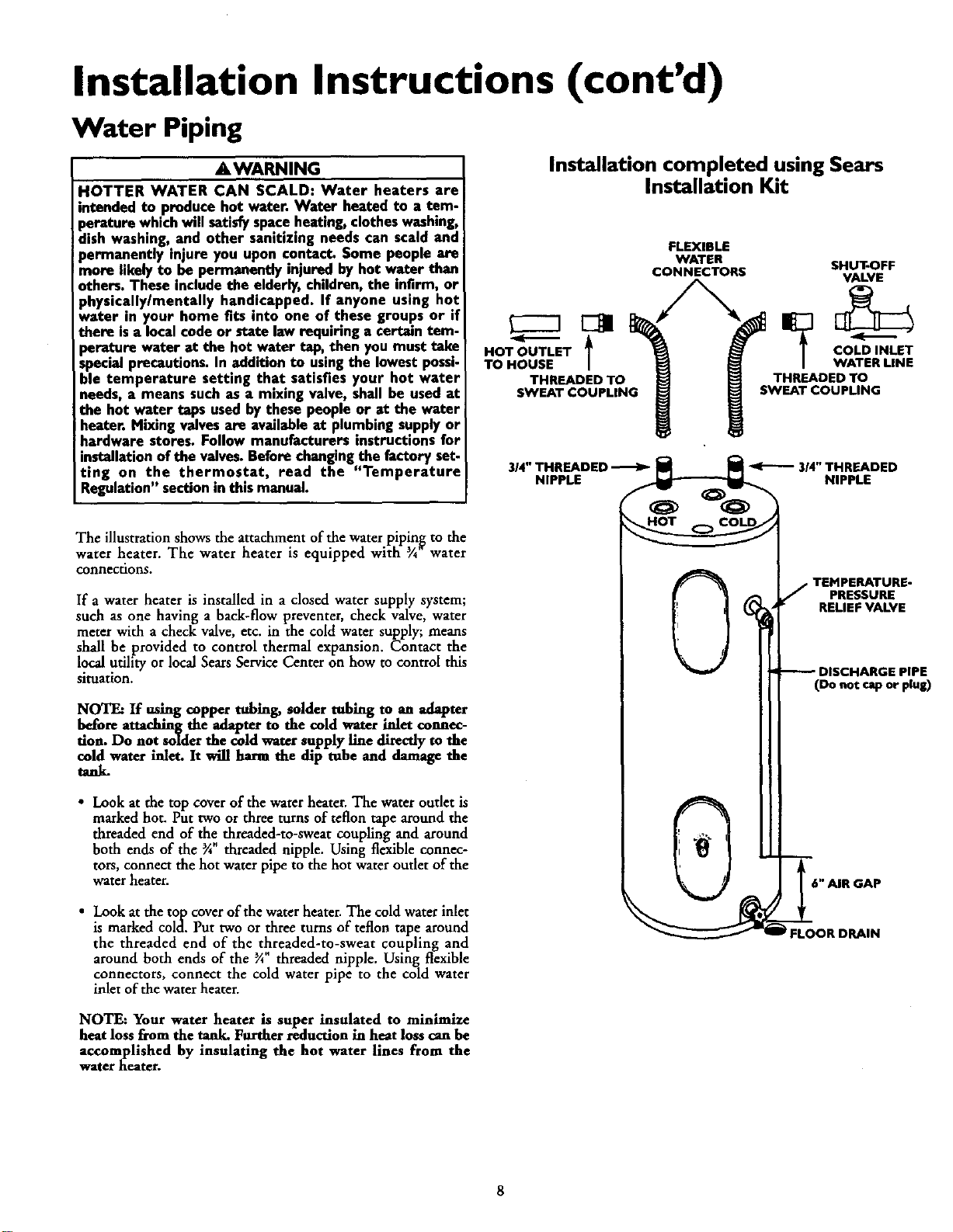
The illustration shows the attachment of the water pipin_ to the
water heater. The water heater is equipped with ¾ water
connections.
If a water heater is installed in a closed water supply system;
such as one having a back-flow preventer, check valve, water
meter with a check valve, etc. in the cold water supply; means
shall be provided to control thermal expansion. Contact the
local utility or local Sears Service Center on how to control this
situation.
NOTE: If using copper tubing, solder tubing to an adapter
before attaching the adapter to the cold water inlet connec-
tion. Do not solder the cold water supply line directly to the
cold water inlet. It will harm the dip tube and damage the
tanL
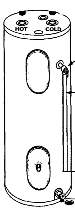
• Look at the top cover of the water heater. The water outlet is
marked hot. Put two or three turns of teflon tape around the
threaded end of the threaded-to-sweat coupling and around
both ends of the _*"threaded nipple. Using flexible connec-
tors, connect the hot water pipe to the hot water outlet of the
water heater.
Installation completed using Sears
Installation Kit
FLEXIBLE
WATER SHUT-OFF
CONNECTORS VALVE
HOT OUTLET / COLD INLET
TO HOUSE WATER LINE
THREADED TO THREADED TO
SWEAT COUPLING SWEAT COUPLING
j TEHPERATURE-
PRESSURE
RELIEF VALVE
DISCHARGE PIPE
(Do not rap or plus)
• Look atthe top cover of the water heater. The cold water inlet
is marked cold. Put two or three turns of teflon tape around
the threaded end of the threaded-to-sweat coupling and
around both ends of the ¼ threaded nipple. Using flexible
connectors, connect the cold water pipe to the cold water
inlet of the water heater.
FLOOR DRAIN
NOTE: Your water heater is super insulated to minimize
heat loss from the tank. Further reduction in heat loss can be
accomplished by insulating the hot water lines from the
w2ter laeatcr.
Installation Instructions (cont'd)
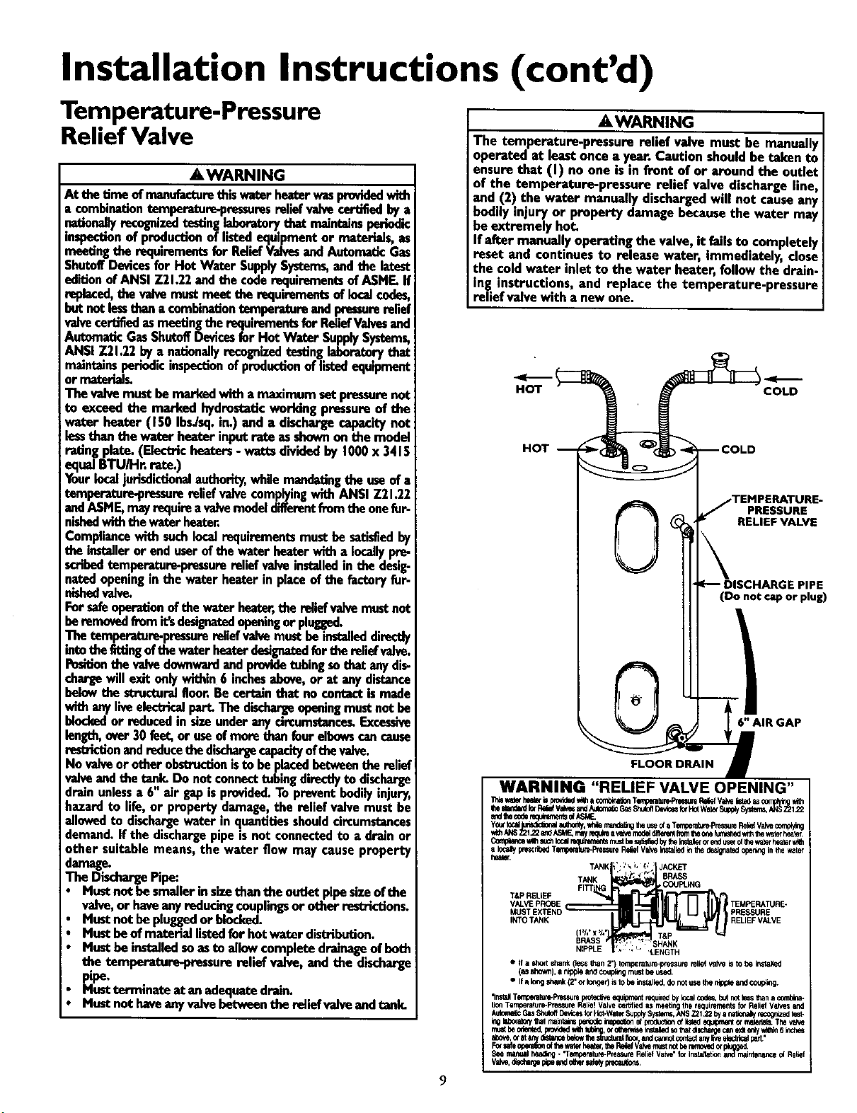
Temperature-Pressure
Relief Valve
A WARNING
At thetimeofmanufacturethiswaterheaterwasprovidedwith
= _.mbinationtemperature-pressuresreliefvalvecertifiedbya
nationallyrecognizedtestinglaboratorythat maintainsperiodic
inspectionof productionoflistedequipmentor matorlaJs,as
meetingthe requirementsfor ReliefValvesandAutomaticGas
ShutoffDevicesfor Hot Water SupplySystems,andthe latest
edition ofANSI Z21.22and the coderequirementsofASME.If
replaced,the valvemustmeet the requirementsoflocalcodes,
but notlessthana combinationtemperatureandpressurerelief
vaivecertifiedasmeetingthe requirementsfor ReliefVaivesand
AutomaticGasShutoffDevicesfor Hot Water SupplySystems,
ANSI Z21.22 bya nationallyrecognizedtestinglaberatorythat
maintainsperiodic inspectionof productionof listedequipment
or materla_
The valvemustbemarkedwith a maximum setprassurenot
to exceed the marked hydrostaticworkingpressureof the
water heater (150 IbsJsq.in.) and a dischargecapacitynot
lessthan the water heater inputrate asshownon the model
ratingplate.(Electricheaters- watts dh6dedby 1000x 3415
equal BTU/Hr. rate.)
Yourlocaljurisdictionalauthority,whilemandatingthe useofa
temperature-pressurerelief valvecomplyingwith ANSI Z21.22
andASME,mayrequireavalvemodeldifferentfromtheonefop
nishedwiththe waterheater.
Compliancewith suchIocelrequirements mustbesatisfiedby
the installeror end userofthe w_er heaterwith a locallypre-
scribedtemperature-pressurerelief valveinstalledin thedesig-
natodopeninginthe waterheater in placeof the factoryfur-
nishodvalve.
Forsafeoper'_on efthe waterheater,the reliefvaivemustnot
beremovedfromit_designatedopeningor plugged.
The temperature-pressurerelief.v_. mustbeinstalleddirectly
intothefittingof thewaterheaterdesignatedfor thereliefvaive.
Pesitionthevalvedownwardandprovidetobing suthat anydis-
chargewill exit onlywithin6 inchesabove,or at any distance
belowthe structuralfloor.Becertainthat no contactismade
with anyliveelect_ part.The dischargeopeningmustnot be
blockedor reducedin sizeunderanydmumstence_Excessive
length,over30 feet,or useofmorethanfourelbowscancause
restrict_nandreducethedischargecapacityof thevalve.
No valveor otherob_n isto be placedbetweenthe relief
valveand the tank. Do notconnecttubingdirectlyto discharge
drainunlessa 6" air gapisprovided.To preventbodilyinjury,
hazardto life,or propertydamage,the reliefvalvemustbe
ailowedto dischargewater in quantitiesshouldcircumstances
demand.If the dischargepipeisnot connectedto a drain or
other suitable means, the water flow may causeproperty
damage.
The DischargePipe:
• Mustnot be smailerin sizethantbe outletpipesizeof the
valve,or haveanyreducingcouplingsor otherrestrictions.
• Mustnot be pluggedor blocked.
• Mustbeof materiellistedfor hot water distribution.
• Mustbeinstalledsoasto allowcompletedrainageofboth
the temperature-pressure reliefvalve, and the discharge
pipe.
• Mustterminnte at anadequatedrain.
• Mustnot haveanyvaivebetweentbe reliofvalveandtank.
AWARNING
The temperature-pressure relief valve must be manually
operated at leastonce a year. Caution shouldbe taken to
ensurethat (I) no one isin front of or around the outlet
of the temperature-pressure relief valve discharge line,
and (2) the water manually dischargedwill not causeany
bodilyinjury or property damage becausethe water may
beextremely hot.
If after manuallyoperating the valve, it failsto completely
reset and continuesto release water, immediately, close
the coldwater inlet to the water heater, follow the drain.
ing instructions, and replace the temperature-pressure
relief valvewith a newone.
HOT
HOT
COLD
PRESSURE
RELIEF VALVE
(Do not cap or plug)
6" AIR GAP
FLOOR DRAIN
9
Installation Instructions (cont'd)
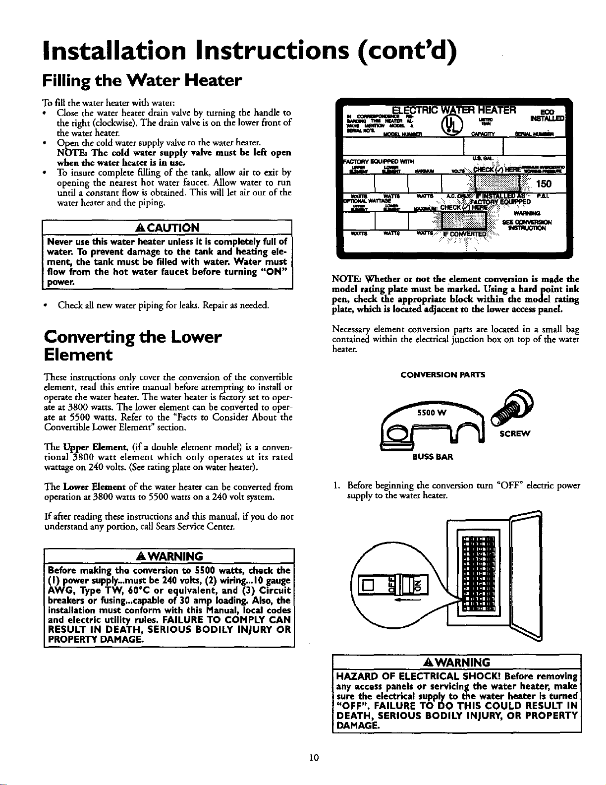
Filling the Water Heater
To fill the water heater with water:
• Close the water heater drain valve by turning the handle to
the right (clockwise). The drain valve is on the lower front of
the water heater.
Open the cold water supply valve to the water heater.
NOTE: The cold water supply valve must be left open
when the water heater is in use.
• To insure complete filling of the tank, allow air to exit by
opening the nearest hot water faucet. Allow water to run
until a constant flow is obtained. This will let air out of the
water heater and the piping.
• ACAUTION {
Never usethis water heater unlessit iscompletely full of I
I water. To prevent damage to the tank and heating ele-
ment, the tank must be filled with water• Water must I
flow from the hot water faucet before turning "ON" I
I power. I
Check all new water piping for leaks. Repair asneeded.
NOTE: Whether or not the .element conversion is made the
model rating plate must be marked. Us'.mga hardpoint ink
pen, check the appropriate block within the model rating
plate, which is located adjacent to the lower access panel.
Converting the Lower
Element
Necessary element conversion parts are located in a small bag
contained within the electrical junction box on top of the water
heater.
These instructions only cover the conversion of the convertible
element, read this entire manual before attempting to install or
operate the water heater. The water heater is factory set to oper-
ate at 3800 watts. The lower element can be converted to oper-
ate at 5500 watts. Refer to the "Facts to Consider About the
Convertible Lower Element" section.
The Upper Element, (if a double element model) is a conven-
tional 3800 watt element which only operates at its rated
wattage on 240 volts. (See rating plate on water heater).
CONVERSION PARTS
BUSS BAR
The Lower Element of the water heater can be converted from
operation at3800 watts to 5500 watts on a240 volt system.
1. Before beginning the conversion turn "OFF" electric power
supply to the water heater.
If afterreading these instructions and this manual, if you do not
understand any portion, call SearsService Center.
AWARNING
Before making the conversionto 5500 watts, check the
(I) power supply...must be 240 volts, (2) wiring...10 gauge
AWG, Type TW, 60°C or eqmvalent, and (3) Circuit
breakers or fusing...capableof 30 amp loading• Also, the
installation must conform with this Manual, local codes
and electric utility rules• FAILURE TO COMPLY CAN
RESULT IN DEATH, SERIOUS BODILY INJURY OR
PROPERTY DAMAGE.
AWARNING
HAZARD OF ELECTRICAL SHOCKI Before removing
any access panels or servicing the water heater, make
sure the electrical supplyto the water heater is turned
"OFF". FAILURE TO DO THIS COULD RESULT IN
DEATH, SERIOUS BODILY INJURY, OR PROPERTY
DAMAGE•
10
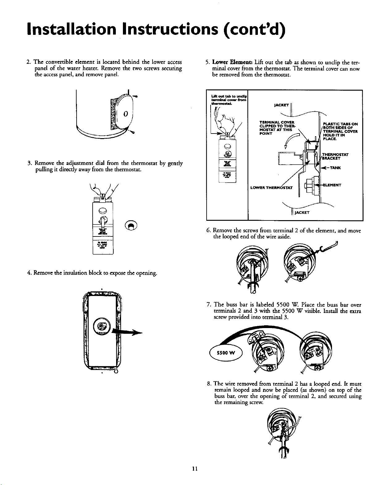
Installation Instructions (cont'd)
2. The convertible element is located behind the lower access
panel of the water heater. Remove the two screws securing
the accesspanel, and remove panel.
5. Lower Element: Lifr out the tab as shown to unclip the ter-
minal cover from the thermostat. The terminal cover can now
be removed from the thermostat.
3. Remove the adjustment dial from the thermostat by gently
pulling it directly awayfrom the thermostat.
4. Remove the insulation block to expose the opening.
,AO
TERMINAL COVER
CLIPPED TO THER-
TATT'S
L
,-.4
LOWER THERMOSTAT
PLASTIC TABS ON
'BOTH SIDES OF
TERMINAL COVER
HOLD IT IN
PLACE.
THERMOSTAT
BRACKET
TANK
_LEMENT
6. Remove the screws from terminal 2 of the element, and move
the looped end of the wire aside.
7. The buss bar is labeled 5500 W. Place the buss bar over
terminals 2 and 3 with the 5500 W visible. Install the extra
screw provided into terminal 3.
5500W
8. The wire removed from terminal 2 has a looped end. It must
remain looped and now be placed (as shown) on top of the
buss bar, over the opening of terminal 2, and secured using
the remaining screw.
11
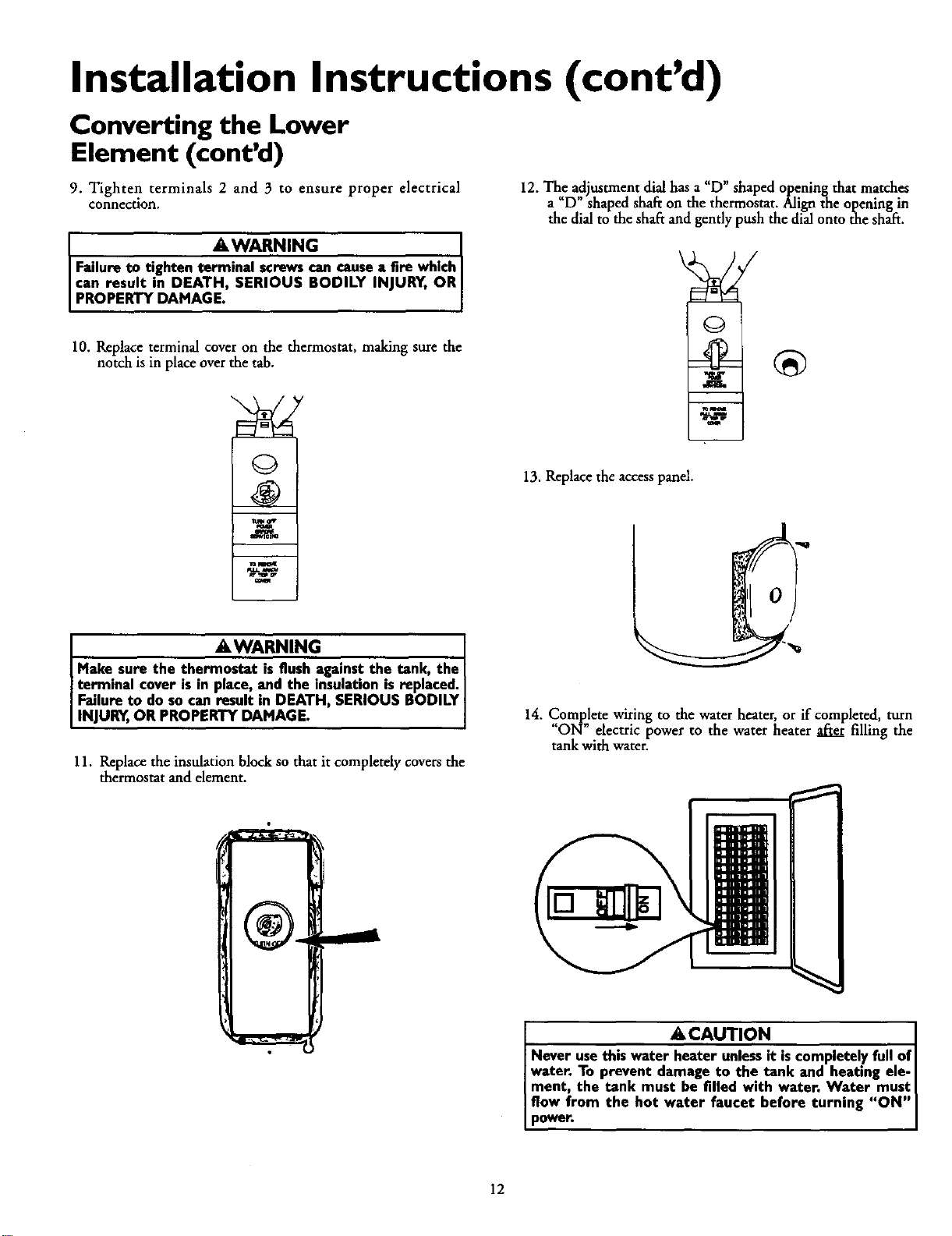
Installation Instructions (cont'd)
Converting the Lower
Element (cont'd)
9. Tighten terminals 2 and 3 to ensure proper electrical
connection.
AWARNING [
Failure to tighten terminal screwscan causea fire which
can result in DEATH, SERIOUS BODILY INJURY. OR
PROPERTY DAMAGE.
10. Replace terminal cover on the thermostat, making sure the
notch is in place over the tab.
Q
_ mI.DG
waa. w
12. The aajustment dial has a "D" shaped opening that matches
a "D" shaped shaft on the thermostat. Align the opening in
the dial to the shaft andgently push the dial onto the shaft.
13. Replace the accesspanel.
AWARNING [
Make sure the thermostat is flush against the tank, the [
terminal cover is in place, and the insulatmn is replaced. [
Failureto do socan result in DEATH, SERIOUS BODILY
INJURY,OR PROPERTY DAMAGE.
11. Replace the insulation block so that it completely covers the
thermostat and element.
14. Complete wiring to the water heater, or if completed, turn
"ON" electric power to the water heater after filling the
tank with water.
ACAUTION
Never usethis water heater unlessit iscompletely full of[
water, To prevent damage to the tank and heating ele-
ment, the tank must he filled with water, Water must [
flow from the hot water faucet before turning "ON"
power.
12
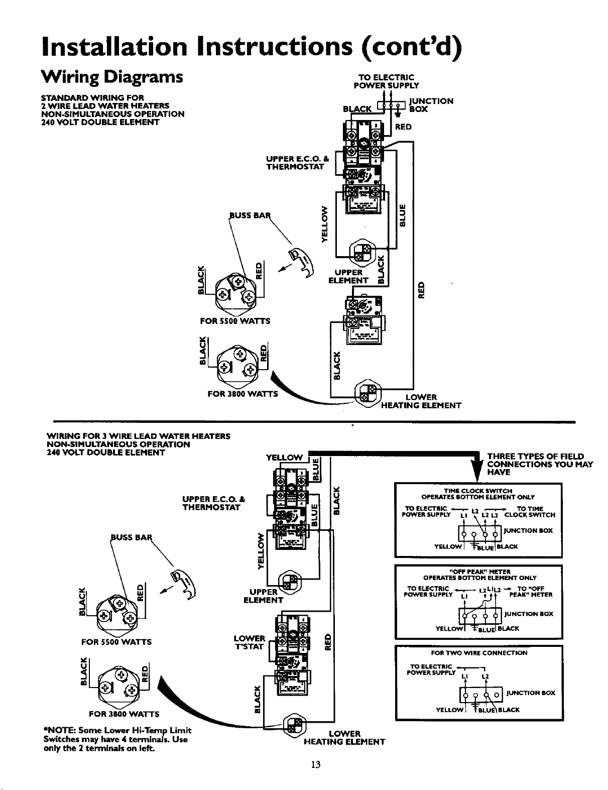
Installation Instructions (cont'd)
Wiring Diagrams
TO ELECTRIC
POWER SUPPLY
STANDARD WIRING FOR
2 WIRE LEAD WATER HEATERS
NON-SIMULTANEOUS OPERATION
240 VOLT DOUBLE ELEMENT
BLACK
JNCTION
RED
UPPER E.C.O. &
THERMOSTAT
!USSBA
FOR 8500 WATTS
UPPER
ELEMENT
FOR 3800 WATTS
LOWER
HEATING ELEMENT
WIRING FOR 3 WIRE LEAD WATER HEATERS
NON-SIMULTANEOUS OPERATION
240 VOLT DOUBLE ELEMENT
UPPER E.C.O. &
THERMOSTAT
IUSS BA_
FOR 5500 WATTS
FOR 3800 WATTS
*NOTE: Some Lower Hi-Temp Limit
Switches may have 4 terminals. Use
only the 2 terminals on left.
ELEMENT
LOWER
T'STAT
YELLOW m
LOWER
HEATING ELEMENT
13
t HREE TYPES OF FIELD
CONNECTIONS YOU MAY
HAVE
TIME CLOCK SWITCH
OPERATES BOTTOM ELEMENT ONLY
TOELECTRIC _- 1.2 _ TOT]HE
POWER SUPPLY LI L2 1.2 CLOCK SWITCH
J_@BI PNCTION BOX
YEll_ CK
"OFF PEAK" NETER
OPERATES BOTTOM ELENENT ONLY
TOELECTR_ _ L2LIL2 -_ TO"OFF
POWER SUPPLY LI t pEAK" METER
_ JUNCTION BOX
YELL LACK
FOR TWO WIRE CONNECTION
LI L2
OW[_B JUNCTION BOX
YELL U_CK
Installation Instructions (cont'd)
Wiring
ACAUTION
Never use this water heater unless,t is completely full of I
water. To prevent damage to the tank and heating ele- I
ment, the tank must be filled w,th water. Water must
flow from the hot water faucet beforeturning on power.
You must provide all wiring of the proper size outside of the
water heater. You must obey local codes and electric company
requirements when you install this wiring.
If you arenot familiar with electric codes and practices, or if you
have any doubt, even the slightest doubt, in your ability to con-
nect the wiring to this water heater, obtain the service of a com-
petent electrician. Contact your Sears salesperson to arrange for
aprofessional electrician.
C. Flexible metal conduit or flexible metallic tubing shall be
permitted for grounding if all the following conditions are
mer_
1. The length in any ground return path does not exceed
6 feet.
2. The circuit conductors contained therein are protected
by overcurrentdevices ratedat 20 amperes or less.
3. The conduit or tubing is terminated in fittings
approved for grounding.
For complete grounding details and all allowable exceptions,
refer to the latest edition of the National Electrical Code.
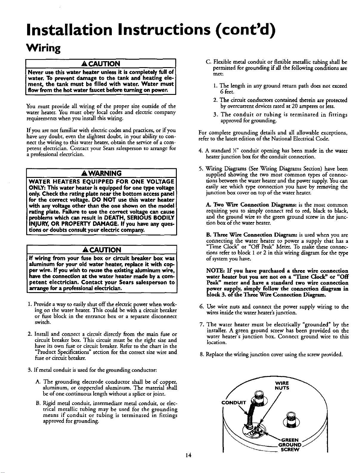
4. A standard _A"conduit opening has been made in the water
heater junction box for the conduit connection.
AWARNING
WATER HEATERS EQUIPPED FOR ONE VOLTAGE
ONLY: Thiswater heater isequippedfor one type voltage
only.Check the rating plate near the bottom accesspanel
for the correct voltage. DO NOT use this water heater
with any voltageother than the one shownon the model
rating plate. Failure to usethe correct voltage can cause
problems which can result in DEATH, SERIOUS BODILY
INJURY,OR PROPERTY DAMAGE. If you haveany ques-
tionsor doubtsconsultyourelectric company.
A CAUTION
If wiring from your fuse box or circuit breaker box was
aluminum for your old water heater, replace it with cop-
per wire. If youwish to reuse the existingaluminum wire,
havethe connectmnat the water heater made by a com-
petent electrician. Contact your Sears salesperson to
arrange for a professionalelectrician.
1. Provide a way to easily shut offthe electric power when work-
ing on the water heater. This could be with a circuit breaker
or fuse block in the entrance box or a separate disconnect
switch.
2. Install and connect a circuit directly from the main fuse or
circuit breaker box. This circuit must be the right size and
have its own fuse or circuit breaker. Refer to the chart in the
"ProductSpecifications" section for the correct size wire and
fuse or circuit breaker.
5. Wiring Diagrams (See Wiring Diagrams Section) have been
supplied showing the two most common types of connec-
tions between the water heater and the power supply, You can
easily see which type connection you have by removing the
junction box cover on top of the water heater.
A, Two W'tre Connection Diagrams: is the most common
requiring you to simply connect red to red, black to black,
and the ground wire to the green ground screw in the junc-
tion box of the water beater.
,
7.
B. Three Wire Connection Diagram: is used when you are
connecting the water heater to power a supply that has a
_Time Clock or _Off Peak" Meter. To make these connec-
tions refer to block 1or 2 in this wiring diagram for the type
of system you have.
NOTE: If you have purchased a ,th,tee wire conne ,cfi,_on
water heater but you are not on a T'nne Clocka' or Off
Peak" meter and have a standard two wire connection
_ower supply, simply follow the connection diagram in
lock 3. of the Three WareConnection Diagram.
Use wire nuts and connect the power supply wiring to the
wires inside the water heater's junction.
The water heater must be electrically _grounded" by the
installer. A _reen ground screw has been provided on the
water heater s junction box. Connect ground wire to this
location.
8. Replace the wiring junction cover using the screw provided.
3. If metal conduit is used for the grounding conductor:
A. The grounding electrode conductor shall be of copper,
aluminum, or copperclad aluminum. The material shall
be of one continuous length without a splice orjoint.
B. Rigid metal conduit, intermediate metal conduit, or elec-
trical metallic tubing may be used for the grounding
means if conduit or tubing is terminated in fittings
approved for grounding.
CONDUIT
WIRE
NUTS
.GREEN
GROUND
SCREW
14
Installation Instructions (cont'd)
Installation Checklist
• Whether or not the element conversion is made, the model
rating plate must be marked. Using a hard point ink pen,
check the appropriate block within the model rating plate,
which is located adjacent to the lower accesspanel.
• Is the fuse or circuit breaker size correct as shown in the chart
in the "Product Specifications" section?
• Are the wires from the circuit breaker or fuse service to the
water heater's junction box on the correct wire size (gauge) as
shown m the chart in the "Product Spec'fications" section?
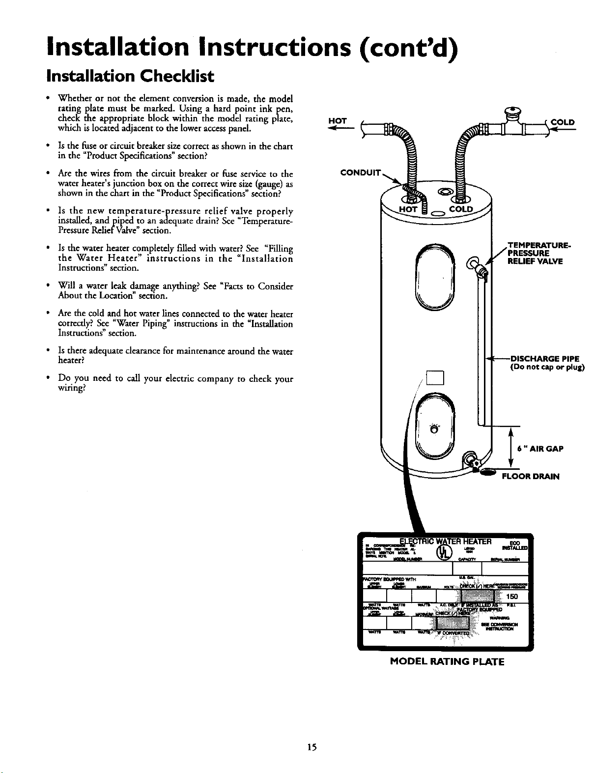
Is the new temperature-pressure relief valve properly
installed, and piped to an adequate drain? See "Temperarure-
Pressure Relief Valve" section.
• Is the water heater completely filled with water? See "Filling
the Water Heater" instructions in the "Installation
Instructions" section.
Will a water leak damage anything? See _Facts to Consider
About the Location" section.
• Are the cold and hot water lines connected to the water heater
correctly?. See "Water Piping" instructions in the "Installation
Instructions" section.
• Is there adequate clearance for maintenance around the water
heater?
• Do you need to call your electric company to check your
wiring?
HOT
/[]
COLD
TEMPERATURE-
JPRESSURE
RELIEF VALVE
F---DISCHARGE PIPE
(Do no_ cap or plug)
6 "AIR GAP
FLOOR DRAIN
MODEL RATING PLATE
15
Service and Adjustment
Temperature Regulation
AWARNING
HOTTER WATER CAN SCALD: Water heaters are
intended to produce hot water. Water heated to a tem-
perature whichwill satisfyspaceheating,clotheswashing,
dish washing, and other saniUzing needs can scald and
permanently injure you upon contact. Some people are
more likely to be permanently injured by hot water than
others. These include the elderly,children, the infirm, or
physically/mentally handicapped. If anyone using hot
water in your home fits into one of these groups or if
there isa local code or state law requiring a certain tem-
perature water at the hot water tap, then you must take
specialprecautions. In addition to usingthe lowest possi-
ble temperature setting that satisfies your hot water
needs, a means such as a mixing valve, shall be used at
the hot water taps usedby these people or at the water
heater. Mixing valvesare available at plumbing supply or
hardware stores. Follow manufacturers instructions for
installationof the valves.Beforechangingthe factory set-
ting on the thermostat, read the "Temperature
Regulation"sectionin this manual.
The lower thermostat is factory set at its lowest position which
approximates 120°F (Hot) and is adjustable if a different water
temperature is desired. Read all warnings in this manual and on
the water heater before proceeding.
Temperature Settings
HOT-Is a thermostat setting of approximately 120°F,
which will supply hot water at the most economi-
caltemperatures.
A-Is a thermostat setting of approximately 130°E
B-Is a thermostat setting of approximately 140°E
C-Is a thermostat setting of approximately 150°E
VERY HOT-Is a thermostat setting of approximately 160°E It
is recommended that the dial be set lower when-
ever possible.
AWARNING
Never allow small children to use a hot water tap, or to
draw their own bath water. Never leavea child or handi-
cappedperson unattended n a bathtub or shower.
Thermostats
The thermostat(s) of this water heater have been factory set at
their lowest position which approximates 120°F (Hot) to reduce
the risk of scald injury.
The upper thermostat is factory set at its lowest position which
approximates 120°F (Hot) and is adjustable if a different water
temperature is desired. Read all warnings in this manual and on
the water heater before proceeding.
NOTE: Water temperature range of 120°--140°F recom-
mended by most dishwasher manufacturers.
Upper Thermostat
Adjustment
NOTE: It is not necessary to adjust the upper thermostat.
However, if it is adjusted above the factory set point of
120°F (HOT) it is recommended that it not be set higher
than the lower thermostat setting.
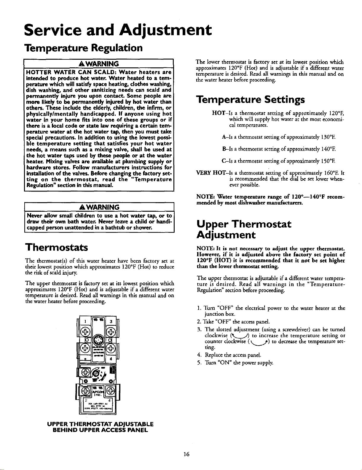
The upper thermostat is adjustable if a different water tempera-
ture is desired. Read all warnings in the _Temperature-
Regulation"section before proceeding.
1. Turn "OFF" the electrical power to the water heater at the
junction box.
2. Take _OFF" the accesspanel.
3. The slotted adjustment (using a screwdriver) can be turned
clockwise (*__.../) to increase the temperature setting or
counter clockwise (_._.._) to decrease the temperature set-
tmg.
4. Replace the accesspanel.
5. Turn "ON" the power supply.
UPPER THERMOSTAT ADJUSTABLE
BEHIND UPPER ACCESS PANEL
16
Service and Adjustment (cont'd)
Lower Thermostat
Adjustment
The lower thermostat is adjustable if a different water tempera-
ture is desired. Read all warnings in the Temperature-
Regulation" section before proceeding.
Failure to install and maintain a new properly listed tempera-
ture-pressure relief valve will release the manufacturer fron_ any
claim which might result from excessivetemperature or pressure.
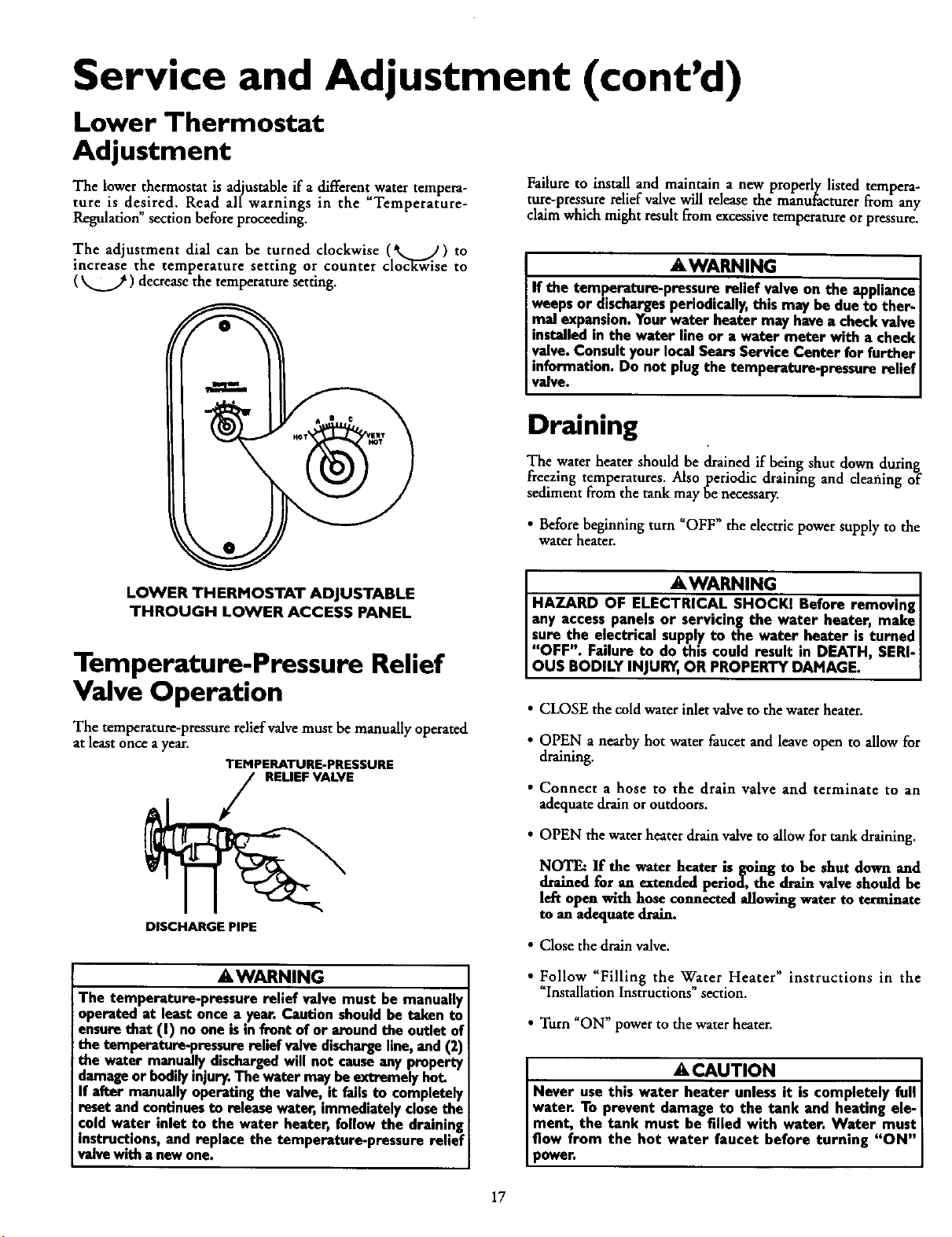
The adjustment dial can be turned clockwise (*k,_ J) to
increase the temperature setting or counter cloc_k-Giseto
( _ ) decrease the temperature setting.
AWARNING
If the temperature-pressure relief valve on the appliance
weepsor dischargesperiodically,this may be due to ther-
mal expansion.Yourwater heater may havea checkvalve
installedin the water line or a water meter with a check
valve.Consultyour localSearsService Center for further
information. Do not plug the temperature-pressure relief
valve.
Draining
The water heater should be drained if being shut down during
freezing temperatures. Also periodic draining and cleaning of
sediment from the tank may be necessary.
• Before beginning turn _OFF" the electric power supply to the
water heater.
LOWER THERMOSTAT ADJUSTABLE
THROUGH LOWER ACCESS PANEL
Temperature-Pressure Relief
Valve Operation
The temperature-pressure relief valve must be manually operated
at least once a year.
TEMPERATURE-PRESSURE
RELIEFVALVE
DISCHARGE PIPE
AWARNING
The temperature-pressure relief valve must be manually
operated at least once a year. Caution shouldhe taken to
ensurethat (I) no one isin front of or around the outlet of
the temperature-pressure relief valve dischargeline, and (2)
the water manuallydischargedwill not causeany property
damageor bodilyinjury.The water maybeextremely hot.
If after manuallyoperatingthe valve, it failsto completely
resetand continuesto release water, immediatelyclosethe
cold water inlet to the water heater, follow the draining
instructions, and replace the temperature-pressure relief
valvewith a newone.
AWARNING ]
HAZARD OF ELECTRICAL SHOCKI Before removing]
any accesspanels or servecingthe water heater, make I
sure the electrical supply to the water heater esturned
"OFF". Failure to do this could result in DEATH SERI-
OUS BODILY INJUR_,OR PROPERTY DAMAGE.
• CLOSE the cold water inlet valve to the water heater.
• OPEN a nearby hot water faucet and leave open to allow for
draining.
• Connect a hose to the drain valve and terminate to an
adequate drain or outdoors.
• OPEN the water heater drain valve to allow for tank draining.
NOTE: If the water heater is going to .be shut down and
drained for an extended periocL the drain valve should be
left open with hose connected allowing water to terminate
to an adequate drain.
• Close the drain valve.
• Follow "Filling the Water Heater" instructions in the
_Installation Instructions" section,
• Turn "ON" power to the water heater.
A CAUTION
Never use this water heater unlessit is completely full
water. To prevent damage to the tank and heating ele- I
ment, the tank must be filled weth water. Water must[
flow from the hot water faucet before turmng "ON"
power.
17
Service and Adjustment (cont'd)
Element Cleaning/
Replacement
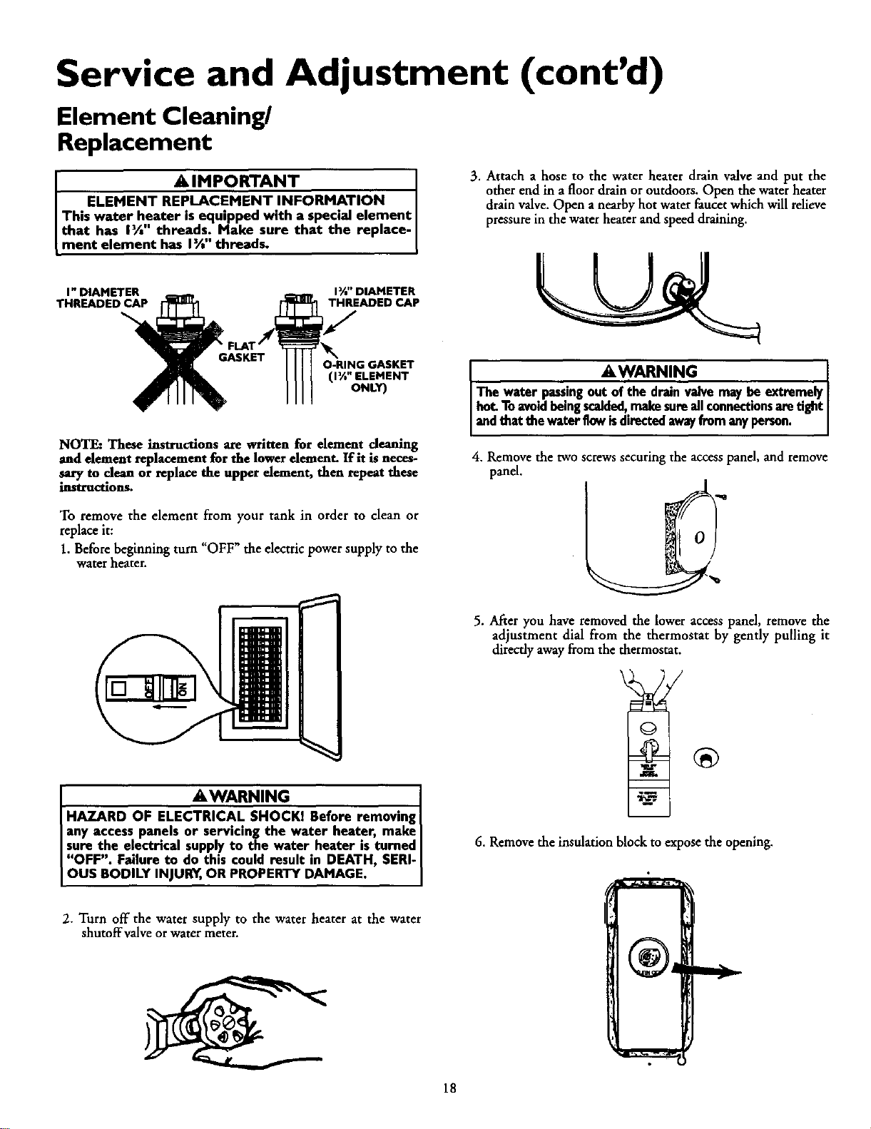
A IMPORTANT I
• ELEMENT REPLACEMENT INFORMATION I
Th,s water h,,eateris equipped with a special element I
that has 1½ threads; Make sure that the replace-[
merit element has 1½ threads.
I" DIAMETER
THREADED CAP
I_" DIAMETER
THREADED CAP
O-RING GASKET
(1½" ELEMENT
ONLY)
NOTE: These instructions are written for element cleaning
and element replacement for the lower element. If it is neces-
sary to clean or replace the upper dement, then repeat these
instructions.
3. Attach a hose to the water heater drain valve and put the
other end in a floor drain or outdoors. Open the water heater
drain valve. Open a nearby hot water faucet which will relieve
pressure in the water heater and speed draining.
AwAa .n 1
The water.passingout of the dnun valvemaybe extremely[
hot.Toavid being scalded,makesureall connectionsaretight/
andthatthewaterflowisdirectedawayfrom anyperson. ]
4. Remove the two screws securing the accesspanel, and remove
panel.
To remove the element from your tank in order to clean or
replace it:
1. Before beginning turn "OFF" the electric power supply to the
water heater.
AWARNING . I
HAZARD OF ELEC_KI Before removing I
any access panels or servicing the water heater, make I
sure the electrical supply to the water heater is turned I
"OFF". Failure to do this could result in DEATH, SERI-I
OUS BODILY INJURY,OR PROPERTY DAMAGE. J
5. After you have removed the lower access panel, remove the
adjustment dial from the thermostat by gently pulling it
directly away from the thermostat.
6. Remove the insulation block to expose the opening.
2. Turn off the water supply to the water heater at the water
shutoffvalve or water meter.
18
Service and Adjustment (cont'd)
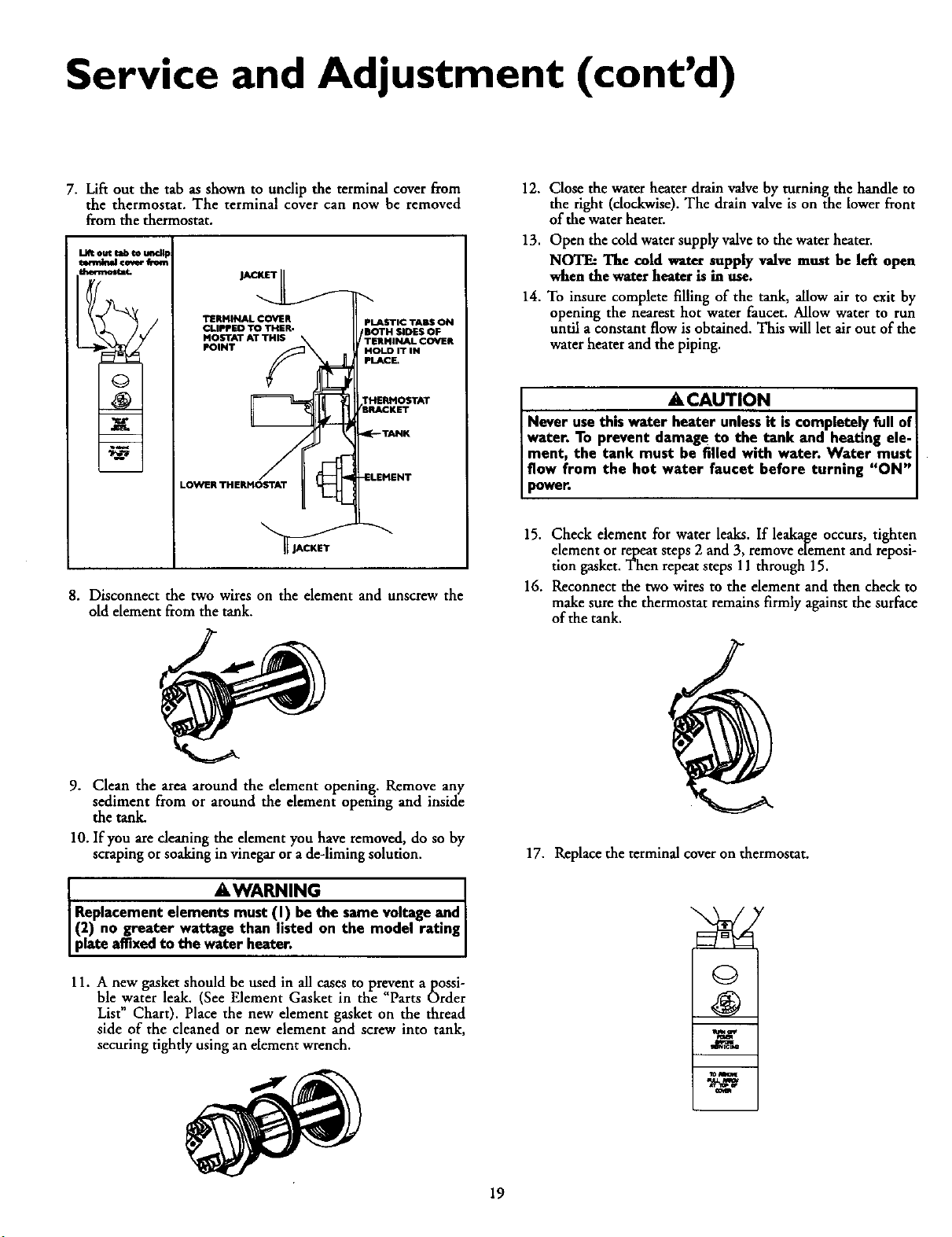
7. Lift out the tab as shown to undip the terminal cover from
the thermostat. The terminal cover can now be removed
from the thermostat.
Ll_ out tsb _ m_d_
TERMINAL COVER
CLIPPED TO THER.
Mob-rAT AT THIS
POINT
m
LOWER THERMOSTAT
PLASTIC TABS ON
'BOTH SIDES OF
TERMINAL COVER
HOLD IT IN
PLACE.
THERHOSTAT
/SRACKST
9_"TANK
_LEHENT
jAC_S_ _
8. Disconnect the two wires on the element and unscrew the
old element from the tank.
12. Close the water heater drain valve by turning the handle to
the right (clockwise). The drain valve is on the lower front
of the waterheater.
13. Open the cold water supply valveto the water heater.
NOTE: The cold water supply valve must be left open
when the water heater is in use.
14. To insure complete filling of the tank, allow air to exit by
opening the nearest hot water faucet. Allow water to run
until aconstant flow is obtained. This will let air out of the
water heater and the piping.
• A CAUTION .
Never use this water heater unless it is complete.l.y full of
water. To prevent damage to the tank and heating ele-
ment, the tank must be filled with water. Water must
flow from the hot water faucet before turning "ON"
powen
15. Check element for water leaks. If leakage occurs, tighten
element or repeatsteps 2 and 3, removeelement and reposi-
tion gasket.Then repeatsteps 11 through 15.
16. Reconnect the two wires to the element and then check to
make sure the thermostat remains firmly against the surface
of the tank.
9. Clean the area around the element opening. Remove any
sediment from or around the element opening and inside
the tank.
10. If you arecleaning the element you have removed, do so by
scraping or soaking in vinegar ora de-liming solution.
AWARNING
Replacement elements must (!) be the same voltageand
(2) no greater wattage than hsted on the model rating
p ate affixedto the water heater.
11. A new gasket should be used in all cases to prevent a possi-
ble water leak. (See Element Gasket in the Parts Order
List" Chart). Place the new element gasket on the thread
side of the cleaned or new element and screw into tank,
securing tightly using an element wrench.
17. Replace the terminal cover on thermostat.
©
19
Service and Adjustment (cont'd)
Element Cleaning/
Replacement (cont'd)
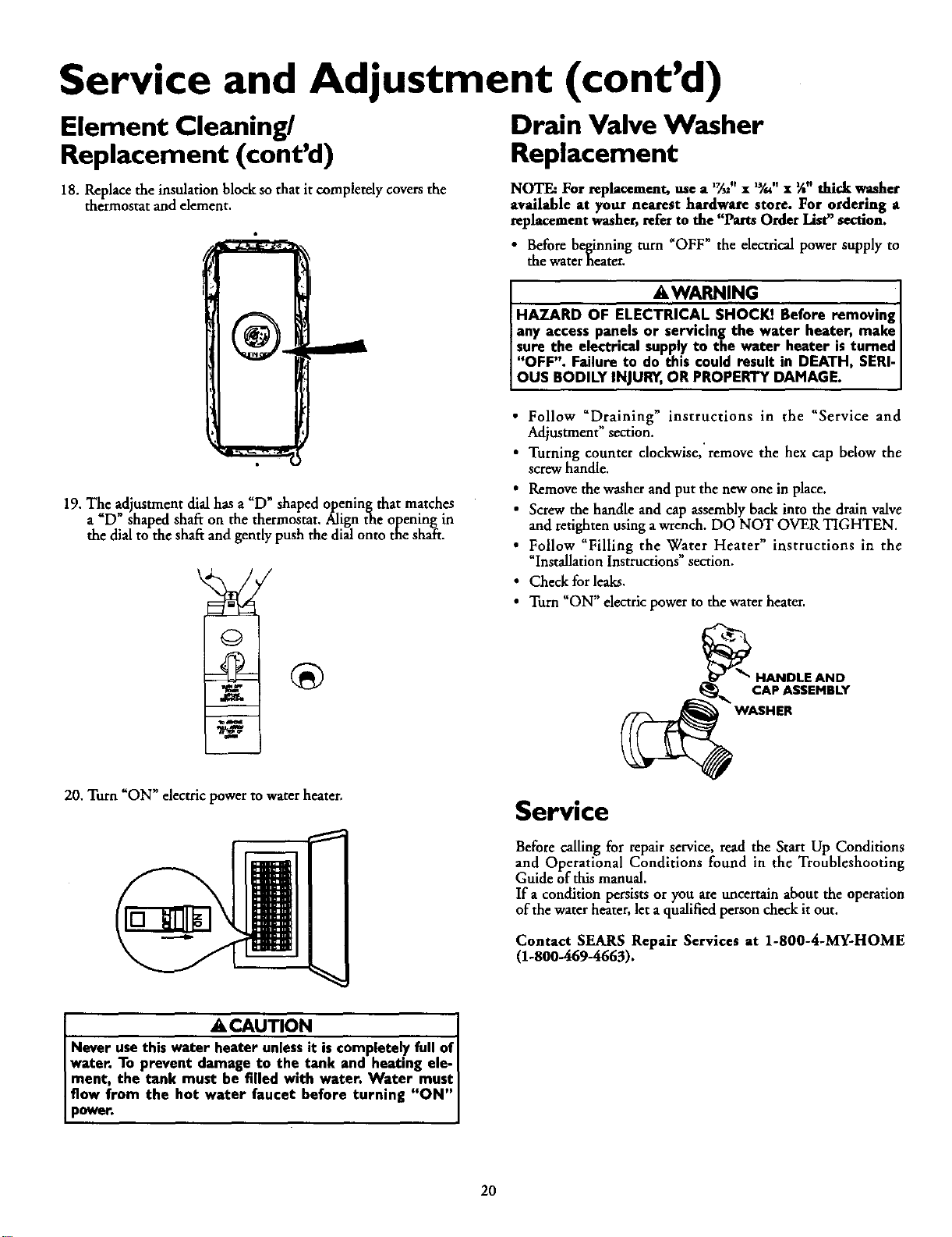
18. Replacethe insulation block so that it completely covers the
thermostat and element.
19. The adjustment dial has a "D"shaped opening that matches
a "D" shaped shaft on the thermostat. Align the opening in
the dial to the shaft and gently push the dial onto the shaft.
20. Turn "ON" electric power to water heater,
Drain Valve Washer
Replacement
NOTE: For replacement, use a 1_,, x W." x %"thick washer
available at your nearest hardware store. For ordering a
replacement washer, refer to the "Parts Order List" section.
• Before beginning turn _OFF" the electrical power supply to
the water heater.
AWARNING . ]
HAZARD OF ELECTRICAL SHOCKI Before removmgl
iany accesspanels or servicing the water heater, make|
sure the electrical supplyto the water heater isturned|
"OFF". Failure to do this could result in DEATH, SERI-|
OUS BODILY INJUI_, OR PROPERTY DAMAGE. i
• Follow "Draining" instructions in the "Service and
Adjustment" section.
• Turning counter clockwise, remove the hex cap below the
screw handle.
• Remove the washer and put the new one in place.
• Screw the handle and cap assembly back into the drain valve
and retighten using a wrench. DO NOT OVER TIGHTEN.
• Follow "Filling the Water Heater" instructions in the
"Iustallation Instructions" section.
• Check for leaks.
• Turn "ON" electric power to the water heater.
_ HANDLE AND
q _, CAP ASSEMBLY
Service
Before calling for repair service, read the Start Up Conditions
and Operational Conditions found in the Troubleshooting
Guide of this manual.
If a condition persists or you are uncertain about the operatLon
of the water heater, let aqualified person check it out.
Contact SEARS Repair Services at 1-800-4-MY-HOME
(1-800-469-4663).
A CAUTION
Never usethis water heater unlessit is completely full of
water. To prevent damage to the tank and heating ele- I
ment, the tank must he filled w*th water. Water must I
flow from the hot water faucet before turning "ON"
power.
2O
Troubleshooting Guide
Start Up Conditions
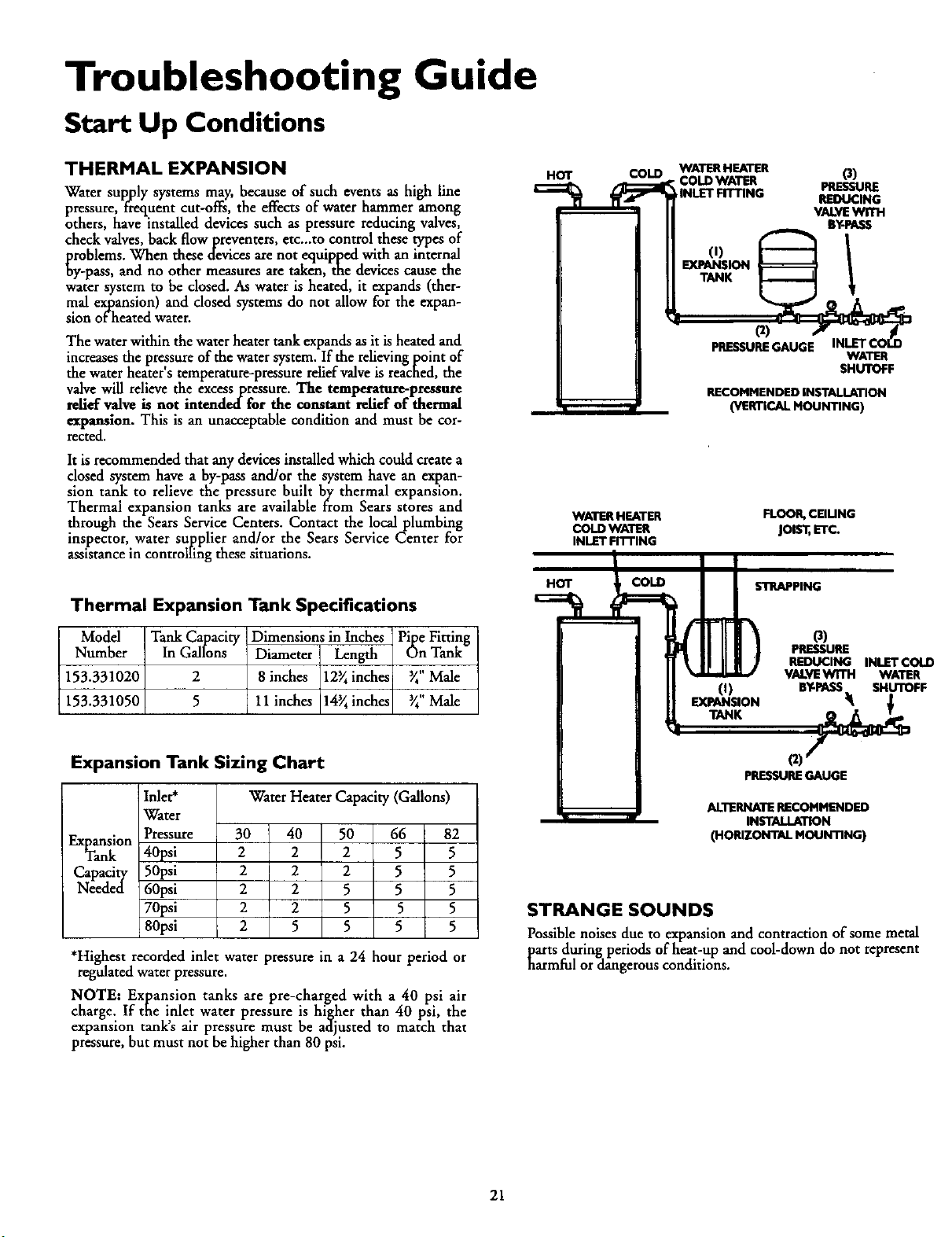
THERMAL EXPANSION
Water supply systems may, because of such events as high line
pressure, f_equent cut-offs, the effects of water hemmer among
others, have installed devices such as pressure reducing valves,
check valves, back flow preventers, etc._to control these types of
problems. When these devices are not equipped with an internal
by-pass, and no other measures are taken, the devices cause the
water system to be closed. As water is heated, it expands (ther-
mal expansion) and closed systems do not allow for the expan-
sion of heated water.
The water within the water heater tank expands as it is heated and
increases the pressure of the water system. If the relieving point of
the water heater s temperature-pressure relief valve is reached, the
valve will relieve the excesspressure. The temperature-pressure
relief valve is not intendedfor the constant relief of thermal
expansion. This is an unacceptable condition and must be cor-
rected.
It is recommended that any devices installed which could create a
closed system have a by-pass and/or the system have an expan-
sion tank to relieve the pressure built by thermal expansion.
Thermal expansion tanks are available from Sears stores and
through the Sears Service Centers. Contact the local plumbing
inspector, water supplier and/or the Sears Service Center for
assistance in controlhng these situations.
Thermal Expansion Tank Specifications
Model Tank Capacity Dimensions in Inches Pipe Fitting
Number In Gallons Diameter Length On Tank
153.331020 2 8 inches 12_ inches _" Male
153.331050 5 11 inches 14_ inches _" Male
HOT
COLD WATER HEATER
COLD WATER
hINLET FITTING
WATER HEATER
COLD WATER
INLET Fn-rlNG
HOT COLD
o)
PRESSURE
REDUCING
VALVEWITH
BY-PASS
(I)
EXPANSION
PRESSUREGAUGE
WATER
SHUTOFF
RECOMMENDED INSTALLATION
(VERTICAL MOUNTING)
FLOOR, CEIUNG
joist, ETC.
s'InRAPPING
O)
EXPANSION
O)
PRESSURE
REDUCING INLET COLD
VALVEWTrH WATER
BY-PASS SHUTOFF
Expansion Tank Sizing Chart
Water Heater Capacity (Gallons)
Inlet*
Water
Pressure
40psi
50psi
60psi
70psi
80psi
Expansion 30 40 50 66 82
Tank 2 2 2 5 5
Capacity 2 2 2 5 5
Needed 2 2 5 5 5
2 2 5 5 5
2 5 5 5 5
*Highest recorded inlet water pressure in a 24 hour period or
regulated water pressure.
NOTE: Expansion tanks are pre-charged with a 40 psi air
charge. If the inlet water pressure is higher than 40 psi, the
expansion tank's air pressure must be adjusted to match that
pressure, but must not be higher than 80 psi.
(2)
pRESSURE GAUGE
ALTERNATE RECOMMENDED
INSTALLATION
(HORIZONTAL MOUNTING)
STRANGE SOUNDS
Possible noises due to expansion and contraction of some metal
parts during periods of heat-up and cool-down do not represent
harmful or dangerous conditions.
21
Troubleshooting Guide (cont'd)
Operational Conditions
RUMBLING NOISE
In some water areas, scale or mineral deposits will build up on
your heating elements. This buildup will cause a rumbling noise.
Follow "Element Cleaning/Replacement" instructions to clean
and replace the elements.
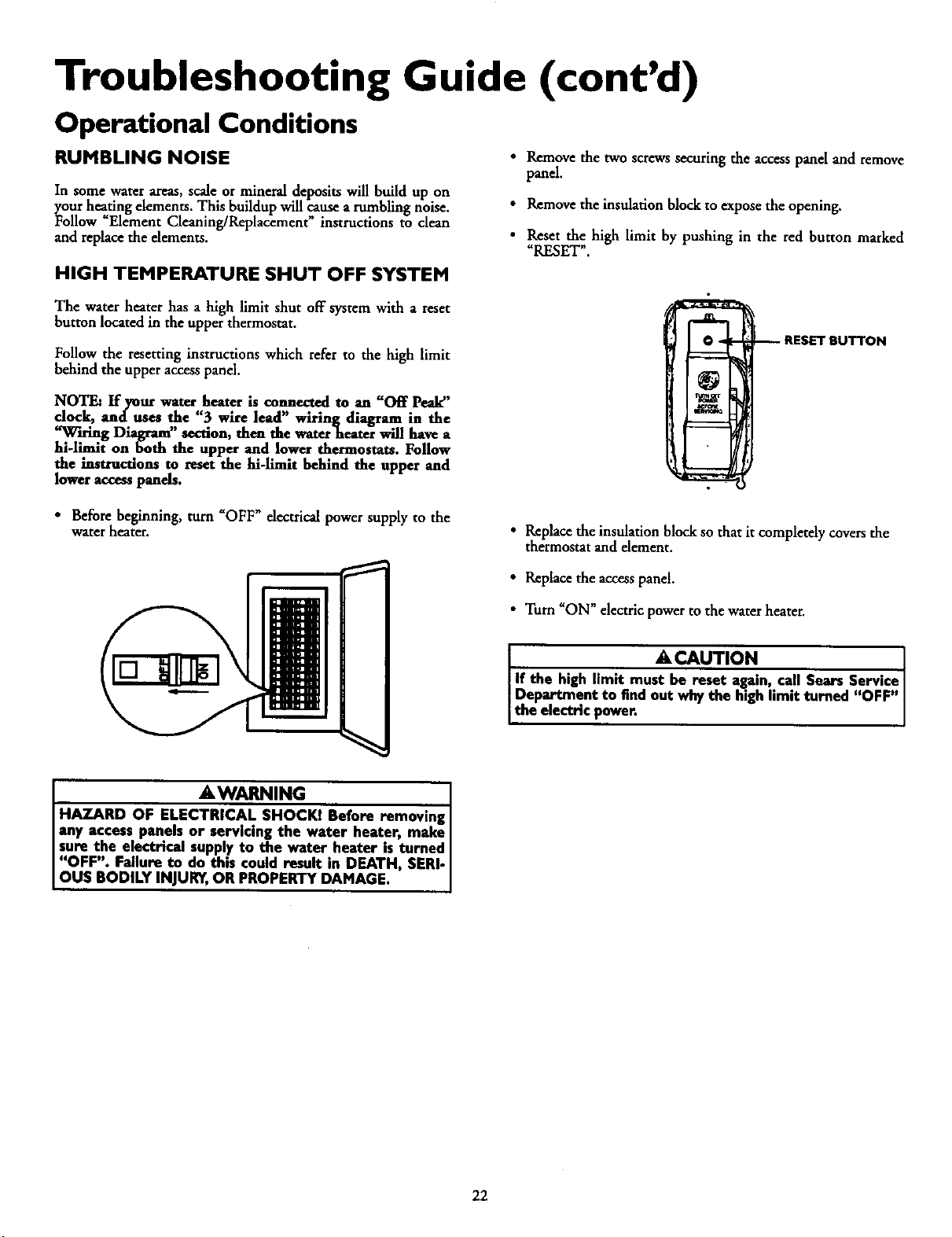
• Remove the two screws securing the access panel and remove
panel,
• Remove the insulation block to expose the opening.
• Reset the high limit by pushing in the red button marked
"RESET".
HIGH TEMPERATURE SHUT OFF SYSTEM
The water heater has a high limit shut off system with a reset
button located in the upper thermostat.
Follow the resetting instructions which refer to the high limit
behind the upper access panel.
NOTE= If your water heater is connected to an "Off Peak"
dock, and uses the "3 wire lead" wiring diagram in the
,.',',_..u_.gDiagram" section, then the water'heater will have a
hi-limit on finth the upper and lower thermostats. Follow
the instructions to reset the M-limit behind the upper and
low.at access ponds.
RESET BUTTON
• Beforebeginning, turn "OFF" dectrical power supply to the
water heater.
• Replace the insulation block so that it completely coversthe
thermostat andelement.
• Replace the accesspanel.
• Turn "ON" electric power to the water heater.
A CAUTION
1
If the high limit must be reset again,.call Sears Service[
Department to find out why the high hmlt turned "OFF"[
the electric power. ]
AWARNING . ]
HAZARD OF ELECTRICAL SHOCKI Before removmg I
any access panels or servicing the water heater, make I
sure the electncai supplyto the water.heater is turned I
"OFF". Failure to do this could result m DEATH, SERI-
OUS BODILY INJURY,OR PROPERTY DAMAGE.
22
Troubleshooting Guide (cont'd)
NOT ENOUGH OR NO HOT WATER
In a new installation, the water heater may not be properly
connected. Make sure the cold water supply valve is open.
Review and check piping installation. Make sure that the
cold water line is connected to the cold water inlet to the
water heater and the hot water line to the hot water outlet
on the water heater.
• Make sure the electrical supply to your water heater is
"ON".
• Check for loose or blown fuses in your water heater circuit.
Circuit breakers weaken with age and may not handle their
rated load and should be replaced.
Make certain the disconnect switch, if used, is in the "ON"
position.
Check to see the electric service to your house has not been
interrupted. If this is the case, contact the electric company.
• Are the thermostats set to the desired temperature? See
"Temperature Regulation" section.
• If you had experienced very hot water and now no hot
water, the problem may be due to the high temperature shut
off system. See _High Temperature Shut Off System" in the
Troubleshooting Guide section.
• During very cold weather, the incoming water will also be
colder and it will require a longer time to become heated.
• The hot water usage may exceed the capacity of the water
heater. If so, wait for water heater to recover after abnormal
demand. Also examine pipes and faucets for possible water
leaks.
• If you can not determine the problem, then call the Sears
Service Department.
WATER IS TOO HOT
_just the thermostat to a lower setting. See the "Temperature
gulation_section.
23
Troubleshooting Guide (cont'd)
Leakage Checkpoints
Use this guide to check a _Leaking" water heater. Many suspect-
ed "Leakers" arenot leaking tanks. Often the source of the water
can be found and corrected.
If you are not thoroughly familiar with electric codes, the water
heater, and safety practices, contact your local
Center to check the water heater.
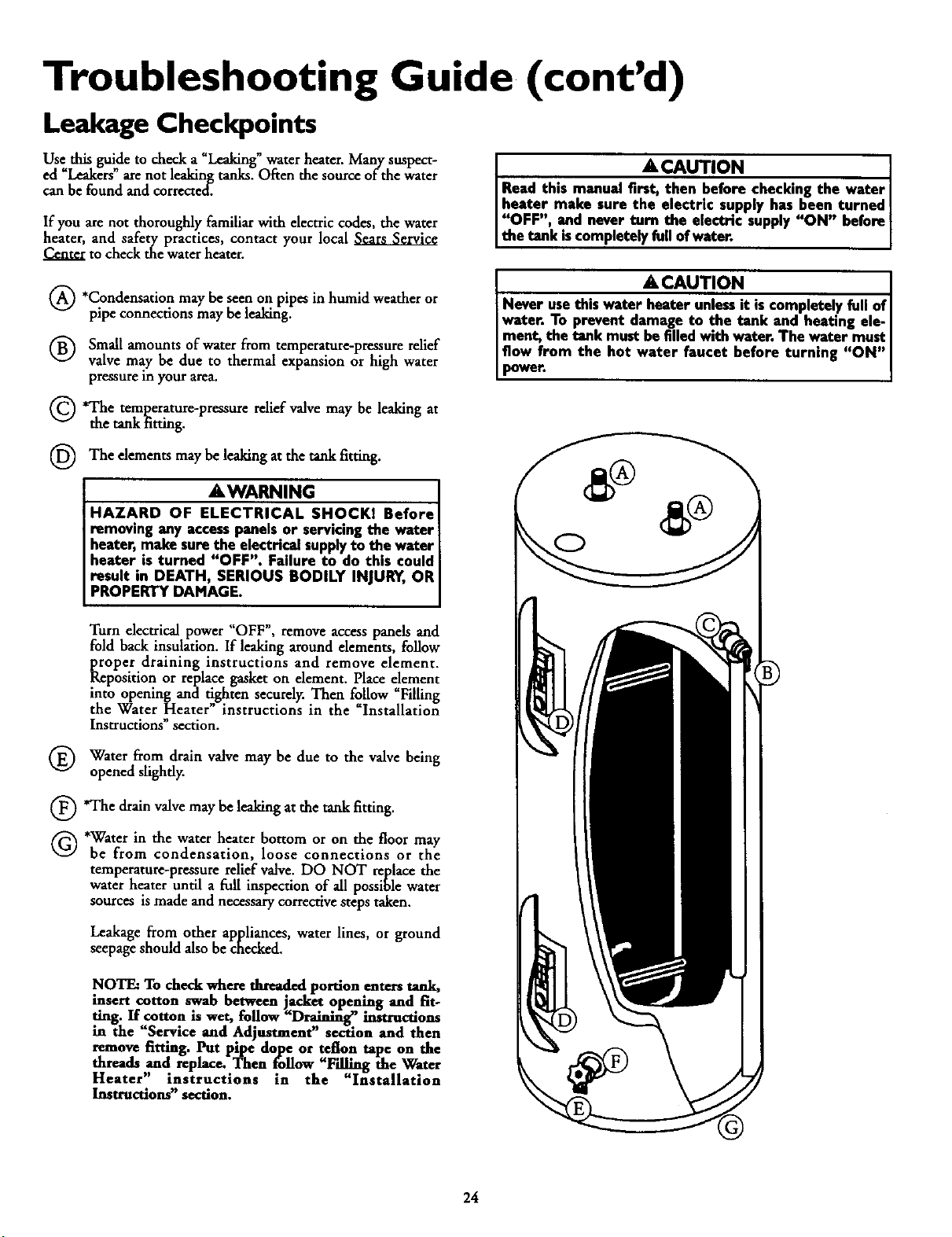
*Condensation may seen on pipes or
be
in humid weather
pipe connections may be leaking.
Small amounts of water from temperature-pressure relief
valve may be due to thermal expansion or high water
pressure in your area.
Q'The temperature-pressure may leaking at
relief valve be
the tank Etting.
(_ The dements be leaking at the tank
may _tting.
AWARNING
HAZARD OF ELECTRICAL SHOCKI Before
removing any accesspanelsor servicingthe water
heater, make sure the electrical supply to the water
heater is turned "OFF". Failure to do this could
result in DEATH, SERIOUS BODILY INJURY, OR
PROPERTY DAMAGE.
. A CAUTION ]
Read th,s manual fi_ checking the water I
heater make sure the electric supply has been turned |
"OFF", and never turn the electric supply "ON" before
the tank iscompletely fullofwater. ]
-CAuT,ON ]
Never usethis water_ iscomplete.lyfull of[
water. To prevent damage to the tank and heating ele-I
ment, the tank must befilled with water. The water must|
flow from the hot water faucet before turning "OH"[
power. ]
Turn electrical power "OFF", remove access panels and
fold back insulation• If leaking around elements, follow
proper draining instructions and remove element.
Reposition or replace gasket on element. Place element
into opening and tighten securely. Then follow "Filling
the Water Heater" instructions in the _Installation
Instructions section.
Water from drain valve may be due to the valve being
opened slightly.
O'The drain valve may be leaking at the tank fitting.
Q *Water in the water heater bottom or on the floor may
be from condensation, loose connections or the
temperature-pressure relief valve. DO NOT replace the
water heater until a full inspection of all possible water
sources is made and necessary corrective steps taken.
Leakage from other appliances, water lines, or ground
seepage should also be checked.
NOTE: To check where flu_. ed portion enters tank,
insert cotton swab between jacket opening and fit-
ring. If cotton is wet, fo.llow "Draining" instructions
in the "Service and Adjustment" section and then
remove fitting. Put pipe dope or teflon tape on the
threads and replace. Then .follow "Filling the Water
Heater" instructions tn the "Installation
Instructions" section.
24

Notes
25
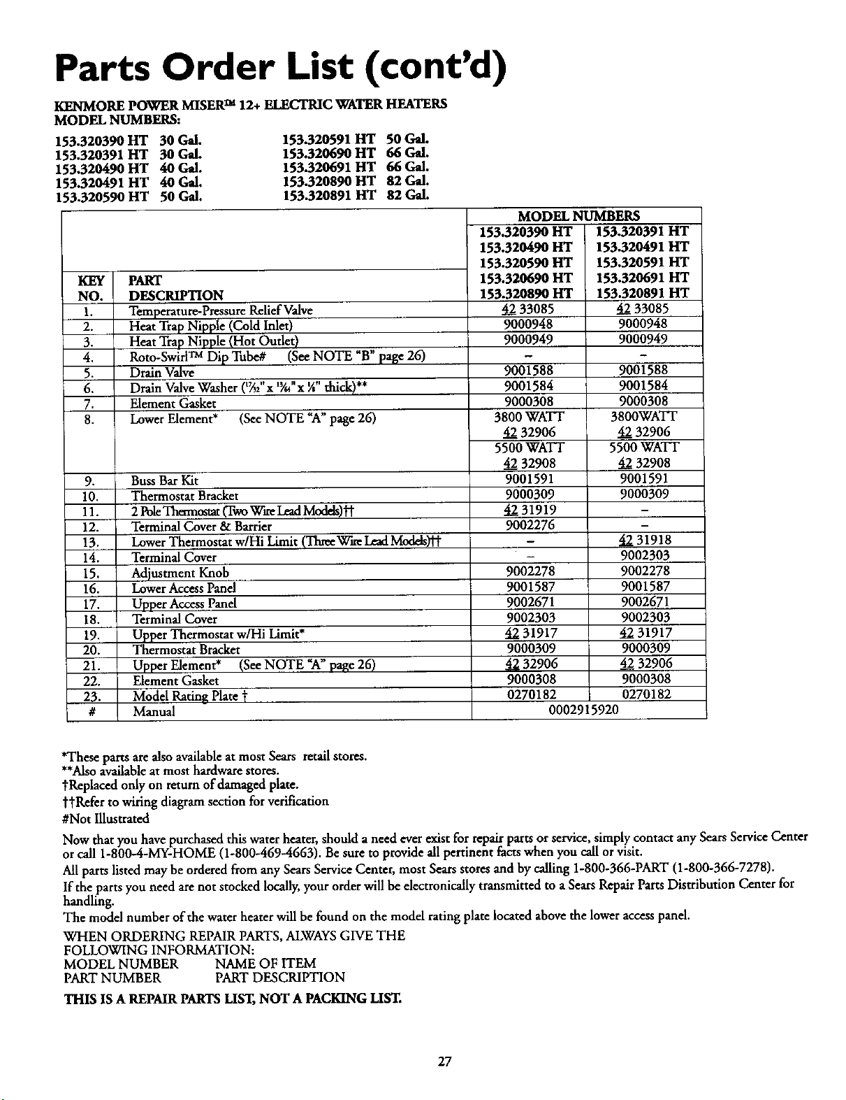
Parts Order List
KENMORE POWER MISERTM 12+ ELECTRIC WATER HEATERS
MODEL NUMBERS:
153.320390 HT 30 Gal.
153.320391 HT 30 Gal.
153.320490 HT 40 Gal.
153.320491 HT 40 Gal.
153.320590 HT 50 Gal.
153.320591 HT 50 Gal.
153.320690 HT 66 Gal.
153.320691 HT 66 Gal.
153.320890 HT 82 Gal.
153.320891 HT 82 Gal.
NOTE_ A
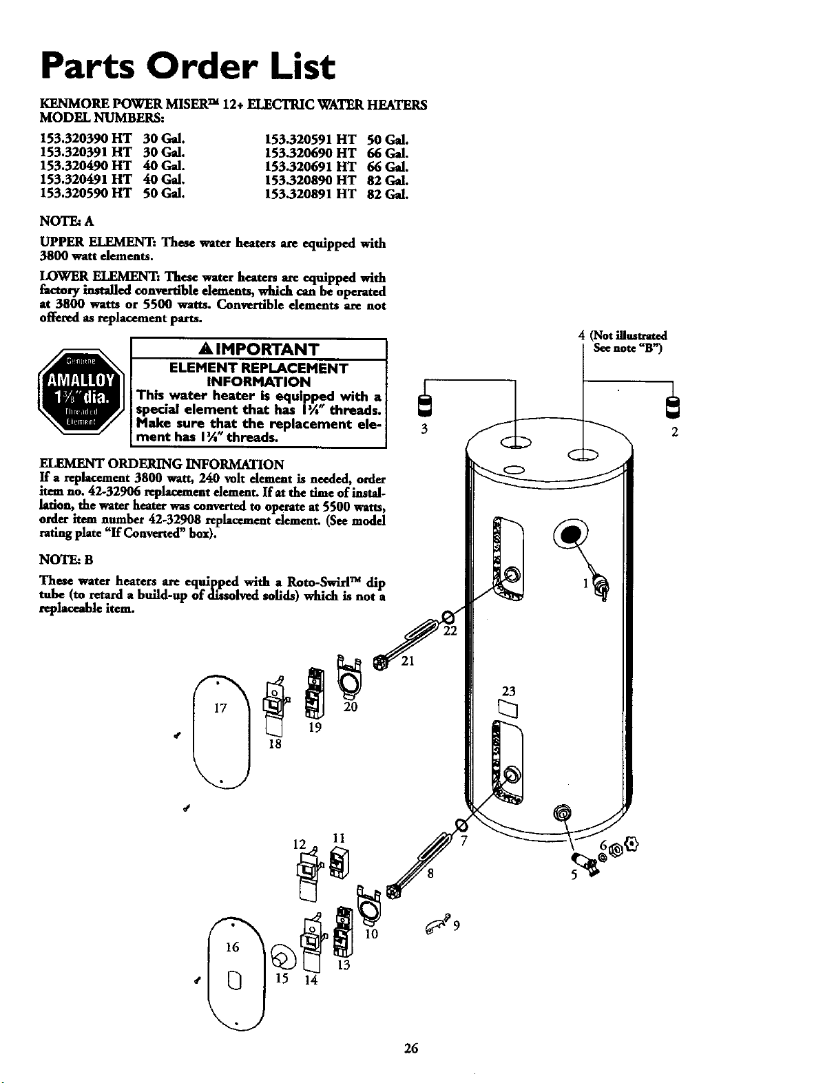
UPPER ELEMENT: These water heaters are equipped with
3800 watt dements.
LOWEll. ELEMENT: These water heaters are equipped with
factory installed convertible dements, .wld'ch can be operated
at 3800 watts or 5500 watts. Converuble elements are not
offered as replacement parts.
A IMPORTANT
ELEMENT REPLACEMENT
INFORMATION
This water heater is equipped with a
special element that has I%" threads.
Make sure that the replacement ele-
ment has I _" threads.
4 (Not10mtrat_l
Seenote "B')
ORDERING INFORMATION
If a replacement 3000 watt, 240 volt dement is needed, order
item no. 42-32906 replacement dement. If at the Ume of instal-
lation, the water heater was converted to operate at 5500 watts,
order item number 42.32908 replacement dement. (See model
rating plate "If Converted" box).
NOTE: B
These water heaters are equipped with a Roto-Swirl TM dip
tube (to retard a build-up of diuolved solids) which is not a
replaceable item.
S
13
14
23
26
Parts Order List (cont'd)
KENMORE POWER MISER TM 12+ ELECTRIC WATER HF_TERS
MODEL NUMBERS:
153.320390 HT 30 Gal.
153.320391 HT 30 Gal.
153.320490 HT 40 Gal.
153.320491 HT 40 Gal.
153.320590 HT 50 Gal.
153.320591 HT 50 Gal.
153.320690 HT 66 Gal.
153.320691 HT 66 Gal.
153.320890 HT 82 Gal.
153.320891 HT 82 Gal.
KEY PART
NO. DESCRIPTION
1. Temperature-Pressure ReliefValve
2. Heat Trap Nipple (Cold Inlet)
3. Heat TrapNipple (Hot Outlet)
4. Roto-Swirl TM Dip Tube# (See NOTE "B" page 26)
5. Drain Valve
6. Drain Valve Washer (t_;' x W-"x *A"thick)**
7. Element Gasket
8. LowerElement* (See NOTE "A"page 26)
.
10.
11.
12.
13.
14.
15.
16.
17.
18.
19.
20.
21.
22.
23.
#
Buss Bar Kit
Thermostat Bracket
2 PoleThermostat (TwoWa-eLeadModds)'M"
Terminal Cover & Barrier
Lower Thermostat w/Hi Limit (Thee Wire LeadModds)'_
Terminal Cover
Adjustment Knob
LowerAccess Panel
Upper AccessPanel
Terminal Cover
Upper Thermostat w/Hi Limit*
Thermostat Bracket
Upper Element* (See NOTE "A" page 26)
Element Gasket
Model Rating Plate t
Manual
MODEL NUMBERS
153.320390 liT 153.320391
153.320490 HT 153.320491
153.320590 lit 153.320591
153.320690HT
153.320890HT
4233085
9000948
9000949
9001588
9001584
9000308
3800WATT
4232906
5500WATT
4232908
9001591
9000309
4231919
9002276
9002278
9001587
9002671
9002303
4231917
9000309
4232906
9000308
0270182
I-IT
HT
HT
153.320691 HT
153.320891 HT
42 33085
9000948
9000949
9001588
9001584
9000308
3800WATt
42 32906
5500 WATT
42 32908
9001591
9000309
4231918
9002303
9002278
9001587
9002671
9002303
4231917
9000309
4232906
9000308
0270182
0002915920
*These parts are also availableat most Seam retail stores.
**Alsoavailableat most hardware stores.
"_Replacedonly on return of damaged plate.
tl"Refer to wiring diagram section for verification
#Not Illustrated
Now that you have purchased this water heater, should a need ever exist for repair parts or service, simply contact any Sears Service Center
or call 1-800-4-MY-HOME (1-800-469-4663). Be sure to provide all pertinent facts when you call or visit.
All parts listed may be orderedfrom any Sears Service Center, most Sears stores and by calling 1-800-366-PART (1-800-366-7278).
If the parts you need are not stocked locally, your orderwill be electronically transmitted to a Sears RepairParts Distribution Center for
handling.
The model number of the water heater will be found on the model rating plate located abovethe lower accesspanel.
WHEN ORDERING REPAIRPARTS, ALWAYSGIVE THE
FOLLOWING INFORMATION:
MODEL NUMBER NAME OF ITEM
PART NUMBER PART DESCRIPTION
THIS IS A REPAIR PARTSLIST, NOT A PACKING LIST.
27
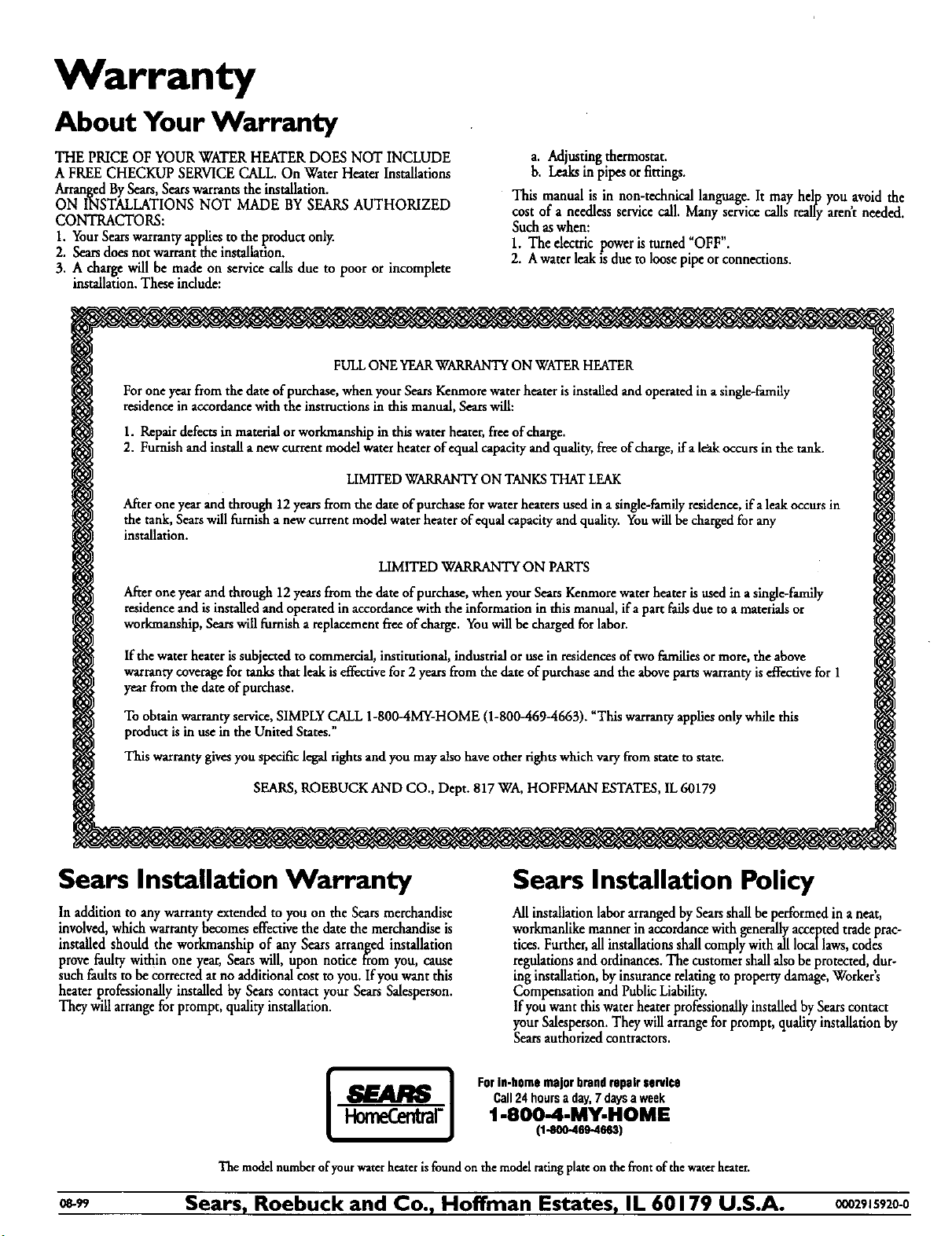
Warranty
About Your Warranty
THE PRICE OF YOUR WATERHEATERDOES NOT INCLUDE
A FREE CHECKUP SERVICECALL.On Water Heater Installations
ArrangedBySears,Searswarrantsthe installation.
ON INSTALLATIONS NOT MADE BYSEARSAUTHORIZED
CONTRACTORS:
1. YourSearswarrantyappliesto the product onl)_
2. Searsdoesnot warrant the installation.
3. A charge will be made on servicecallsdue to poor or incomplete
installation.Theseindude:
a. Adjusting thermostat.
b. Leaks in pipes or fittings.
This manual is in non-technical language. It may help you avoid the
cost of a needless service call. Many service calls really arent needed.
Such as when:
1. The decttic power is turned "OFF".
2. A water leak is due to loose pipe or connections.
FULL ONE YEARWARRANTY ON WATER HEATER
Forone yearfrom the dateofpurchase,when your SearsKenmorewaterheater isinstalledand operatedinasingle-family
residencein accordancewith the instructionsinthis manual,Searswill:
1. Repair defects in material or workmanship in this water heater, free of charge.
2. Furnish and install a new current model water heater of equal capacity and quality, free of charge, if a le_tkoccurs in the tank.
LIMITED WARRANTY ON TANKS THAT LEAK
Afterone yearand through 12yearsfrom the dateofpurchasefor water heatersused in asingle-familyresidence,ifa leakoccursin
the tank,Searswillfurnisha newcurrentmodelwater heaterof equalcapacityand quality. Youwillbe chargedforany
installation.
LIMITED WARRANTY ON PARTS
After one year and through 12 years from the date of purchase, when your Sears Kenmore water heater is used in asingle-family
residence and is installed and operated in accordance with the information in this manual, ifa part fails due to a materials or
workmanship, Sears will furnish a replacement free of charge. You will be charged for labor.
Ifthe water heater issubjectedto commerdal, institutional,industrial orusein residencesoftwo familiesormore, the above
warrantycoveragefor tanksthat leakiseffectivefor 2 yearsfrom the date ofpurchaseand the abovepartswarrantyis effectivefor 1
yearfromthe date of purchase.
To obtain warranty service, SIMPLY CALL 1-800_iMY-HOME (1-800_69-4663). _Tliis warranty applies only while this
product is in use in the United States."
This warrantygivesyouspecificlegalrightsandyoumayalsohaveother rightswhich varyfromstateto state.
SEARS,ROEBUCKAND CO., Dept. 817 WA, HOFFMAN ESTATES,IL60179
Sears Installation Warranty
In addition to any warrantyextended to you on the Searsmerchandise
involved,whichwarranty becomeseffectivethe date the merchandiseis
installed should the workmanship of any Sears arranged installation
provefaulty within oneyear, Searswill, upon notice from you, cause
suchfaultsto beCorrectedatno additionalcostto you. Ifyou want this
heater professionallyinstalledby Searscontact your SearsSalesperson.
Theywillarrangefor prompt, quality installation.
Sears Installation Policy
Allinstallationlaborarrangedby Searsshallbe performed in a neat,
workmanlikemanner in accordancewith generallyacceptedtrade prac-
tices.Further,all installationsshallcomplywith all locallaws,codes
regulationsand ordinances.The customershallalsobeprotected,dur-
inginstallation,by insurancerelatingto propertydamage,Workers
Compensation andPublicLiability.
If youwant thiswaterheater professionallyinstalledbySearscontact
yourSalesperson.Theywill arrangefor prompt, qualityinstalhtion by
Searsauthorized contractors.
For in-home major brand repair service
Call24hoursaday,7daysaweek
"1-800-4-MY-HOME
(1-800-469-4663)
Themodelnumberofyourwaterheaterisfoundonthemedalratingplateon thefrontofthewaterheater.
o8-99 Sears, Roebuck and Co., Hoffman Estates, IL 60179 U.S.A. 0002915920-0