Loading ...
Loading ...
Loading ...
4
560A
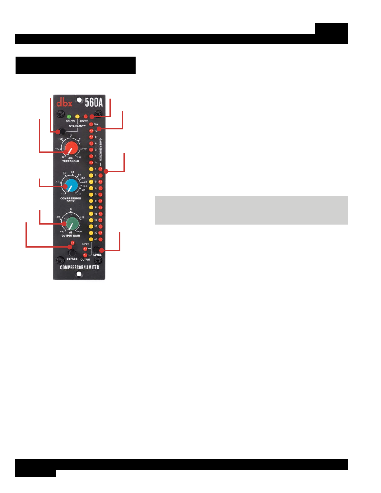
The User Interface
1
2
3
4
5
6
9
8
7
1. OVEREASY
®
Button
This button sets the “knee” of the compressor/limiter. The knee
determines how abrupt or gradual the transition is between compression
and non-compression.
When disengaged, the 560A will operate as a hard knee compressor/
limiter – meaning the transition between compression and
non-compression is sharp or abrupt. This mode works well when a more
aggressively compressed signal is required.
When the OVEREASY button is engaged, the 560A will operate as
a soft knee compressor/limiter – meaning the transition between
compression and non-compression is gradual. This mode works well
when more subtle compression or limiting is required.
NOTE: When the OVEREASY button is engaged, the yellow
OVEREASY LED becomes active and lights when the signal level is in
the OverEasy region, which is just below the set threshold.
2. THRESHOLD Control
Adjust this knob to set the level at which compression or limiting will
begin. The range of this knob is from -40dBu (7.8mVRMS) to +20dBu
(7.8VRMS).
3. COMPRESSION RATIO Control
This control adjusts the amount of gain reduction applied once the signal level exceeds the set THRESHOLD setting.
A setting of 1:1 means there is no change in level between input and output, which means no dynamics processing
will occur regardless of the THRESHOLD setting. The compression/limiting range of this control is from 1:1 (no
compression) up to ∞:1 (maximum limiting).
Rotating this control further clockwise, past the ∞:1 setting, increases compression into the INFINITY+ region, up to a
maximum of -1:1. Where a RATIO setting of ∞:1 essentially puts a “ceiling” on the output signal level and doesn’t allow
any output signal level increase above threshold, negative compression goes further and allows the output signal level to
be reduced even beyond that of the set threshold. In other words, the louder the input signal level is above threshold, the
lower the output signal level will be, without hitting the “floor” of the THRESHOLD setting. This can be used for special
effect applications where the output level needs to be reduced below that of the input signal level. See the “RATIO”
graph in ‘Compression Graphs’ on page 6 to see a graph showing compression curves based on ratio setting,
including a negative compression curve using the -1:1 COMPRESSION RATIO setting.
4. OUTPUT GAIN Control
Adjust this control to compensate for the amount of gain lost during compression/limiting. Making up for lost gain with
this control makes it far easier to compare the processed signal against the unprocessed signal to determine if the
Loading ...
Loading ...
Loading ...