
HUAWEI TECHNOLOGIES CO., LTD.
NetCol8000-C(070, 130, 190) In-room
Chilled Water Smart Cooling Product
Quick Guide
Issue: 04
Part Number: 31500CWQ
Date: 2021-12-30
1
1
Product Overview
Materials
Delivered with
the Equipment
Cord end terminal of the power cable connecting to the indoor unit (2.5 mm
2
or 4 mm
2
or 6 mm
2
), OT ground terminal of the power cable to the indoor unit
(2.5 mm
2
or 6 mm
2
)
Engineering
Purchasing
Drainpipe Rigid pipe: made of PP-R material; 3/4 inch outer
screw thread to rigid pipe connector
Water inlet and outlet
pipe
DN50 rigid pipe with an G 2 inch external threaded
connector
(Optional) Water inlet
pipe for the wet film
humidifier
Rigid pipe: made of PP-R material; G 3/4 inch inner
screw threads to rigid pipe conversion adapter
Other
Hoop iron, cable tie, push mount tie, network cable
for teamwork, power cable, base, pipe support,
thermal insulation foam, dedicated glue for thermal
insulation foam, thread sealant
2
Engineering Materials
Cables
2.1
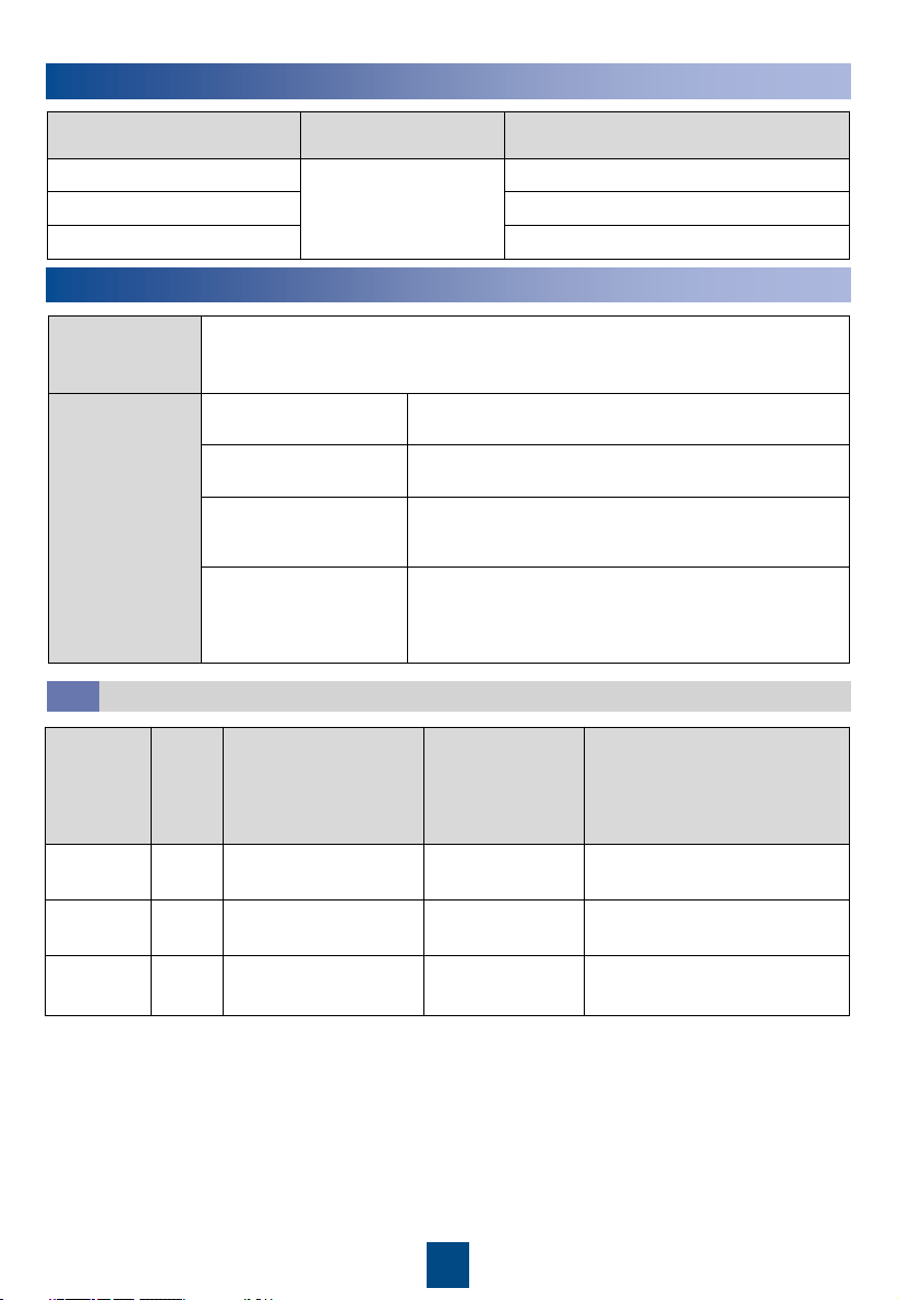
Product Model Pipe Routing
Dimensions Without Packing (H x W x
D) (mm)
NetCol8000-C070
Upflow: routed from
bottom or side
Downflow: routed from
bottom
2000 x 900 x 1000 (single-door)
NetCol8000-C130
2000 x 1800 x 1000 (double-door)
NetCol8000-C190
2000 x 2700 x 1000 (triple-door)
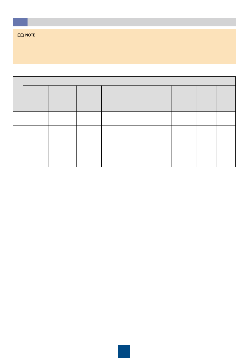
Model Setup
Maximum Current
(cooing only/full
configuration)
Recommended
Switch (cooing
only/full
configuration)
Cable Diameter (cooing
only/full configuration)
NetCol8000
-C070
Dual
route
Active: 7.3 A/16.5 A
Standby: 7.3 A/7.3 A
Active: C16/C32
Standby: C16/C16
Active: 4 x 2.5 mm
2
/4 x 4 mm
2
Standby: 4 x 2.5 mm
2
/4 x4 mm
2
NetCol8000
-C130
Dual
route
Active: 14 A/32.3 A
Standby: 14 A/14 A
Active: C25/C50
Standby: C25/C25
Active: 4 x 4 mm
2
/4 x 6 mm
2
Standby: 4 x 4 mm
2
/4 x 6 mm
2
NetCol8000
-C190
Dual
route
Active: 20.7 A/39 A
Standby: 20.7 A/20.7 A
Active: C40/C63
Standby: C40/C40
Active: 4 x 4 mm
2
/4 x 6 mm
2
Standby: 4 x 4 mm
2
/4 x 6 mm
2
Copyright © Huawei Technologies Co., Ltd. 2021.
All rights reserved.
2
3
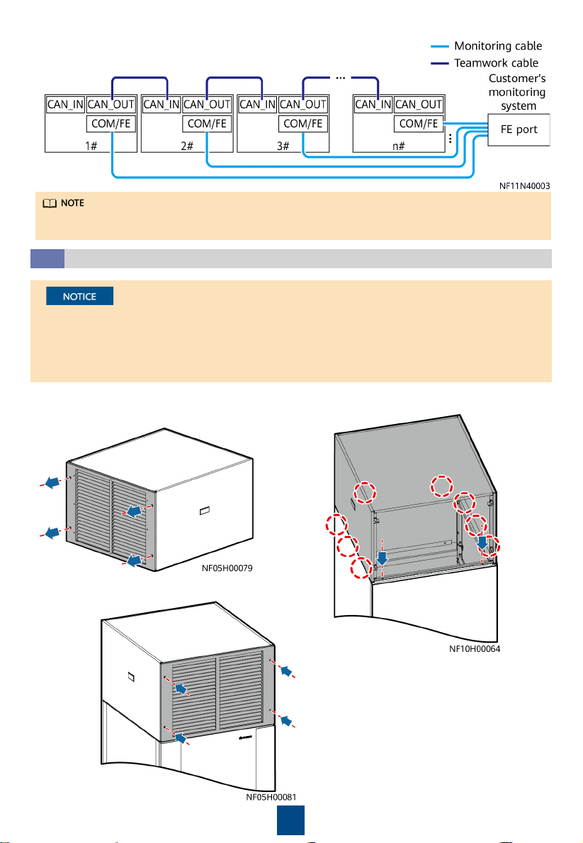
Installing the Cabinet
1. Use insulated tools when installing the equipment.
2. The downflow NetCol8000-C must be installed in the equipment room with a raised floor.
3. Only engineers certified by the manufacturer or its agent are allowed to install, commission,
and maintain the smart cooling product. Otherwise, personal injury or equipment damage
may occur, and the resulting smart cooling product faults are beyond the warranty scope of
Huawei.
4. The electricians onsite must be qualified.
5. If cabinets are not placed abreast, the height of the raised floor should be greater than 550
mm for downflow units, and the height of the raised floor should be greater than 300 mm
for upflow units.
6. If cabinets are placed abreast and pipes are routed from the bottom, the height of the raised
floor should be greater than 800 mm.
7. During installation, place the packaged top panel on the top of the cabinet to prevent the
dust. Remove the top panel before the power-on commissioning.
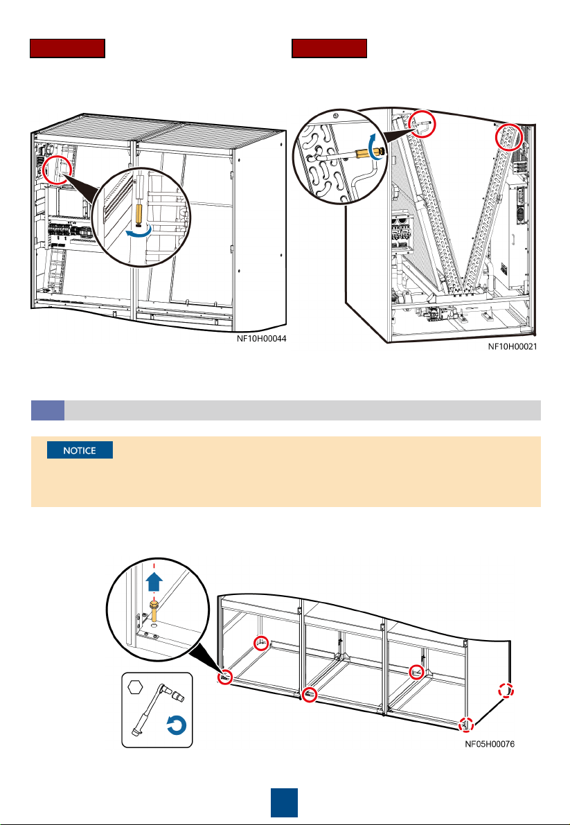
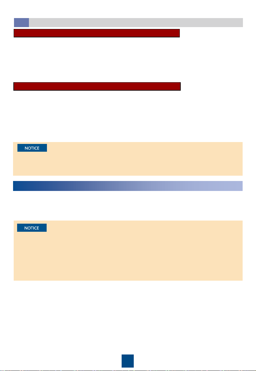
• The equipment is charged with nitrogen before delivery. Rotate the exhaust valve
counterclockwise. If there is a hiss sound, the system is well sealed, and you need to open
the exhaust valve to exhaust the nitrogen. If there is no hiss sound, contact Huawei technical
support.
• After nitrogen is exhausted, remove the desiccant bag bound to the fan.
• You can open or close the exhaust valve using a flat-head screwdriver.
Checking the Nitrogen Pressure and Exhausting Nitrogen
3.1
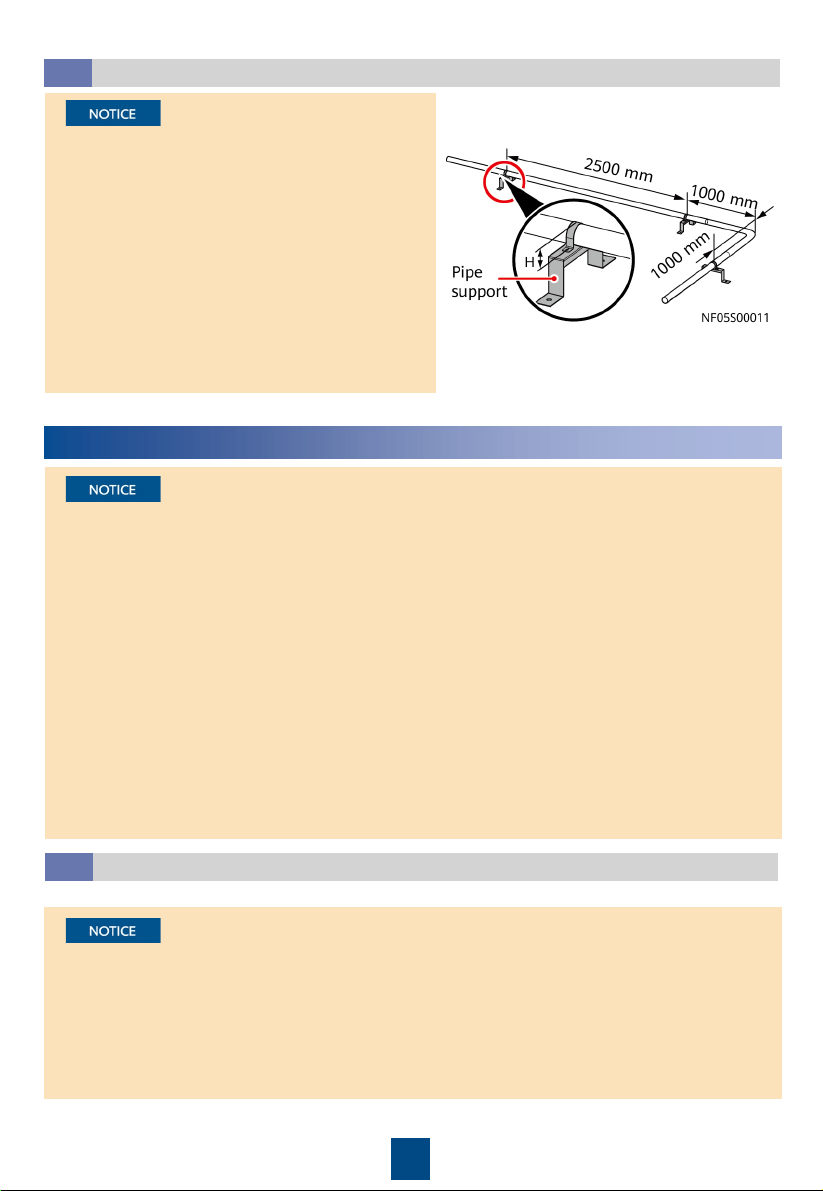
1. The height of a U-shaped pipe clamp equals
the diameter of the pipe with thermal
insulation foam minus 5 mm. The pipe
supports are to be purchased.
2. The material for pipe supports and clamps
should meet outdoor application
requirements.
3. Install a support every 2500 mm in the
straight sections of pipes, and 1000 mm away
from each bending point in the turning
section.
Pipe Support
2.2
3
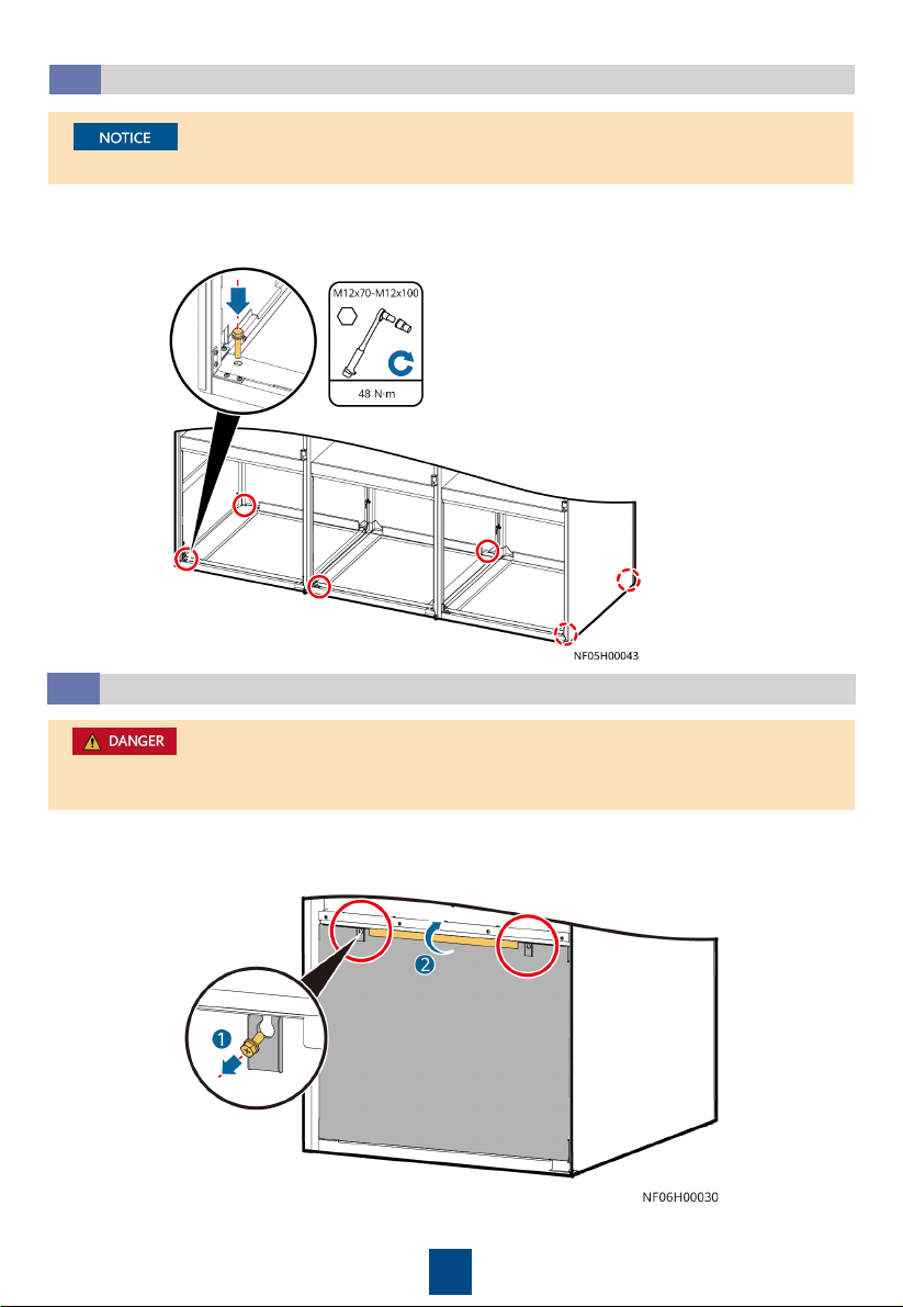
Open the front door and remove the rear door. Remove the bolts that secure the cabinet and
the pallet using a 19# socket wrench.
Removing the Pallet
3.2
1. For downflow units, remove the fan maintenance baffle plate at the front door before
removing the bolts.
2. For a single-door and double-dour cabinet, remove the four screws from both sides.
Downflow Upflow
4
For a single-door and double-door cabinet, tighten the four screws on both sides.
Securing the Equipment
3.3
1. Secure the base to the ground using the six expansion bolts.
2. Move the cabinet onto the base. Secure the cabinet to the base using six bolts. Install a
shock pad between the base and the cabinet.
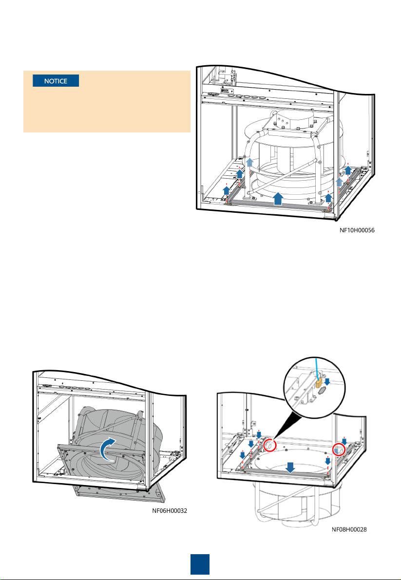
1. Exercise caution when raising or lowering a fan to prevent personal injury.
2. When removing the fan beam, assign one person to hold the fan.
Lowering a Fan (Applicable to Downflow Units)
3.4
a. Open the front door. Loosen the fan maintenance baffle plate and remove it from the
cabinet (using the left fan as an example).
5
b. Remove the six screws from the beams on both sides of the fan, and remove the two screws
on the connecting piece between the fan and the bottom of the cabinet. Remove the beams
and connecting piece.
c. At least two people are required to
rotate the fan. When the fan is 45
degrees to the bottom of the cabinet,
pull the fan along the guide rails on
both sides and rotate it inwards until
the fan is completely horizontal.
d. Place the fan support beam on the top of the
fan, and secure the fan support beam to the
cabinet by using screws, and secure the two
screws on the connecting piece. Connect the
fan signal cable and power cable to the
interconnection port reserved on the fan
panel, and bind the cables.
When removing the fan and connecting
piece between the fans and the bottom
plate, hold the fan to prevent it from
rotating automatically.

6
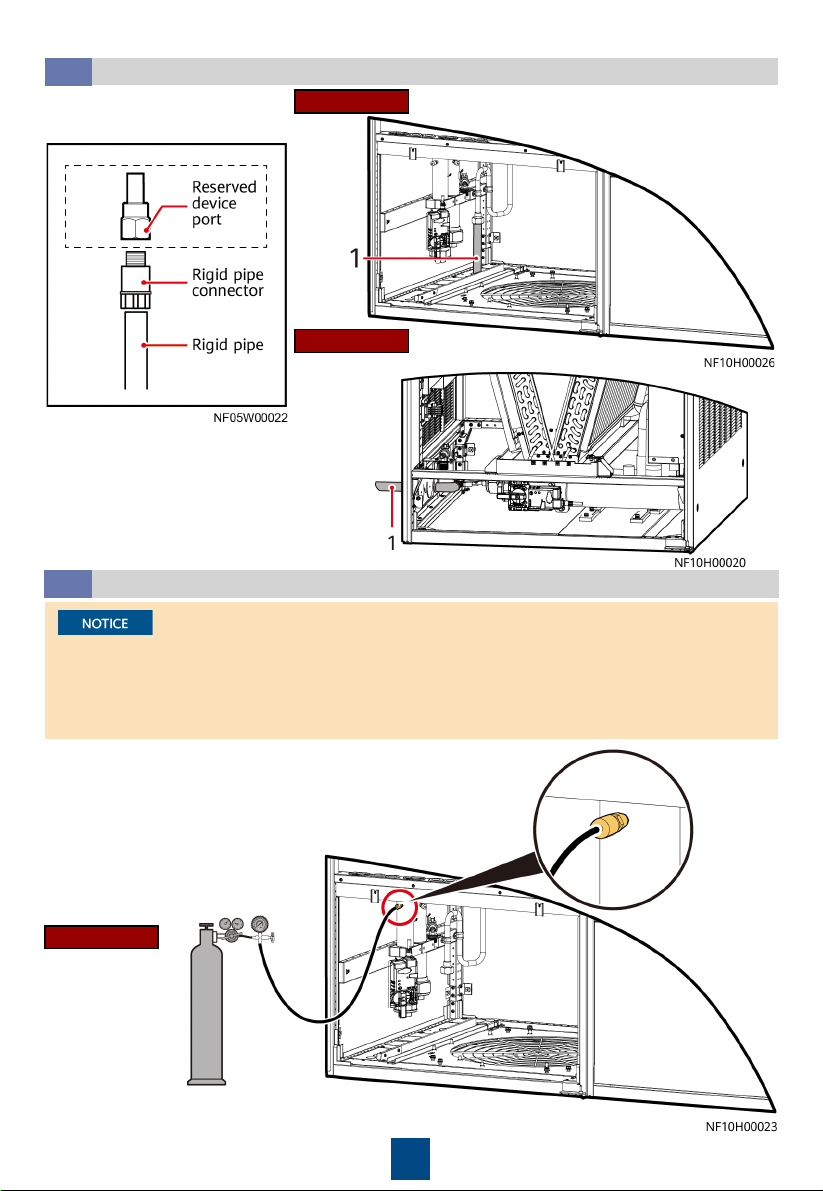
Connecting Water Inlet and Outlet Pipelines
3.5
1. (Skip this step for upflow units.) Remove the baffle plate at the bottom of the cabinet, and
knock off the U-shaped hole in the baffle plate.
2. To avoid deforming the pipe, use a 75# open-end wrench to fix the pipe nut, use a 36#
open-end wrench to fix the plug, and then remove the plug.
3. Apply thread sealant evenly on the joints of external screw threads, and install the pipes
from inside out.
4. Use a 75# open-end wrench and an 18# pipe wrench to fix the pipes.
5. (Skip this step for upflow units.) Install the pipe baffle plate at the bottom of the cabinet,
and wrap the pipe and the baffle plate with thermal insulation foam.
1. Wrap thermal insulation foam around the whole pipes after pipes are connected.
2. Due to the hardening property of yellow adhesive, nitrogen injection and pressure preserve
should be operated 8 hours after the adapter is connected.
Downflow
Upflow
The figure uses side
pipe routing as an
example. If bottom pipe
routing is used,
purchase right angle
elbows with DN50
outer threads onsite.
7
Connecting the Drainpipe
3.6
Upflow
Downflow
Connection method
(1) Drainpipe
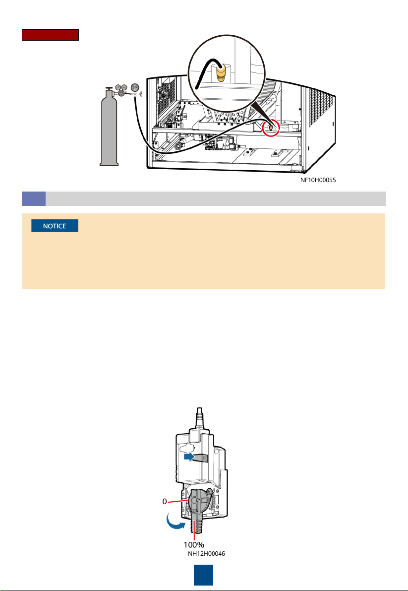
(Optional) Leakage Test with Nitrogen
3.7
1. Rotate the chilled water valve to the maximum openness (100%).
2. Check that the needle valves and exhaust valves on the pipeline
are closed.
• If the pressure decreases, apply soapy water on the pipes, especially pipe joints to check for
any leakage.
• If the pressure is stable, wrap all pipes and connectors with thermal insulation foam.
• Install a reducing valve at the outlet of the nitrogen cylinder. The outlet pressure of the
reducing valve must be not more than 0.8 MPa.
Downflow
(1) Drainpipe
4. Then, check that the pressure
reading on the pressure gauge
remains unchanged.
3. Connect the reducing valve and nitrogen cylinder to the
following needle valve, inject 0.8 MPa (when the pressure is
stable) nitrogen, and leave them for 24 hours.
8
1. Open the general water supply valve.
2. Verify that the chilled water valve is open (100%). If not, press the button on the side of the
actuator, and manually rotate the valve handle to the maximum.
3. Slowly open the exhaust valve to discharge air.
4. Adjust the air exhausting speed until no air flows out of the valve. Then close the exhaust
valve.
5. (If a leakage test with nitrogen has been performed, skip this step.) Raise the water pressure
in the chilled water pipe to 0.8 MPa. If no leakage occurs after 30 minutes, retain the
pressure for 24 hours. The expected result is that the pressure drop is less than 0.01 MPa and
the pipe does not leak.
6. Release the pressure in the pipes, and manually close the chilled water valve.
Leakage Test with Water
3.8
• To avoid blockage of the heat exchanger in the smart cooling product due to foreign
matter from the main pipe during the construction, you are advised to clean the main pipe
before water is supplied to the smart cooling product. Turn off the isolation valves on the
water inlet and outlet pipes before the cleaning and turn them on afterwards.
• Open the exhaust valve of each heat exchanger to exhaust nitrogen onsite.
Upflow
9
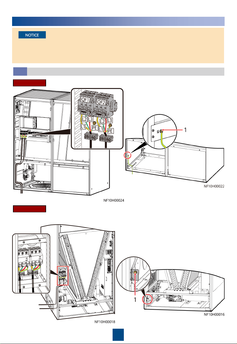
Connecting the Power Cable and Equipotential Bonding Cable
4.1
A ground cable must be routed from the
equipotential bonding point of the cabinet
to the ground.
(1) Equipotential bonding point
4
Connecting Cables
• Cables must be routed in through cable clips.
• Route and bind the cables along the beams and columns of the unit.
• The cabinet has no input neutral wire. You can cut the blue neutral wire and wrap it using
insulation tape.
Upflow
Downflow
A ground cable must be routed from the
equipotential bonding point of the cabinet
to the ground.
(1) Equipotential bonding point
10
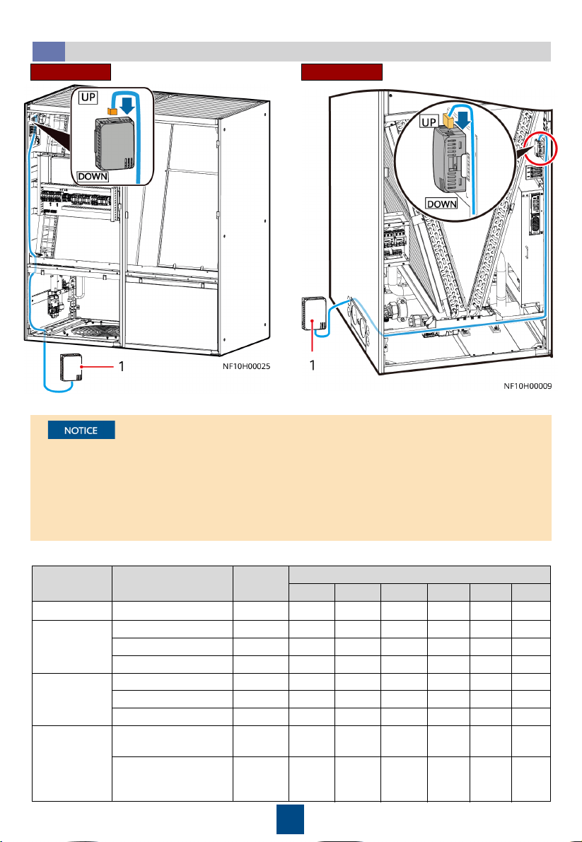
(Optional) Connecting the T/H Sensor Outside the Cabinet
4.2
• The T/H sensors inside the cabinet are secured at the return air side and their UP ports are
connected to the main control board. When connecting the T/H sensors outside the cabinet,
connect the DOWN port of one T/H sensor inside the cabinet to the UP port of the next T/H
sensor outside the cabinet as shown in the following figure. Connect all T/H sensors in series
in this way. and secure them with cable ties or other fasteners.
• The T/H sensors should be installed 1.5 m (33 U) above the floor. Each smart cooling
product supports three T/H sensors in cold aisles and the other three in hot aisles at most.
Position Name Address
DIP Switch Sequence No.
1 2 3 4 5 6
Return-air side Return air T/H 1 1 ON OFF OFF OFF OFF OFF
Cold aisle
Cold aisle T/H 1 11 ON ON OFF ON OFF OFF
Cold aisle T/H 2 12 OFF OFF ON ON OFF OFF
Cold aisle T/H 3 13 ON OFF ON ON OFF OFF
Hot aisle
Hot aisle T/H 1 21 ON OFF ON OFF ON OFF
Hot aisle T/H 2 22 OFF ON ON OFF ON OFF
Hot aisle T/H 3 23 ON ON ON OFF ON OFF
Direct
ventilation
Fresh air temperature
and humidity
29 ON OFF ON ON ON OFF
Temperature and
humidity at the return
air valve
27 ON ON OFF ON ON OFF
DIP Switch Instructions
UpflowDownflow
(1) T/H sensors outside the cabinet
11
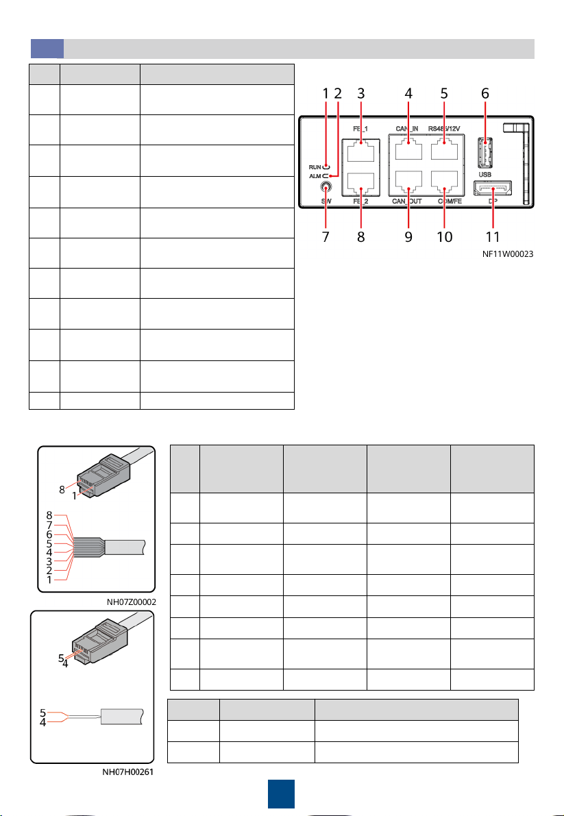
(Optional) Connecting Teamwork and Monitoring Cables
4.3
No. Name Description
1
Running
indicator
-
2
Alarm
indicator
-
3
FE_1 port
Reserved for MAC_CAN
teamwork
4
CAN_IN port
CAN teamwork and RS485
monitoring cascading
5
RS485/12V
port
Connects a temperature and
humidity (T/H) sensor.
6
USB port
Connects a WiFi module or
USB flash drive.
7
SW button
Button for restoring factory
settings
8
FE_2 port
Reserved for MAC_CAN
teamwork
9
CAN_OUT port
CAN teamwork and RS485
monitoring cascading
10
COM/FE port
Connects a monitoring
communications cable.
11
DP port Connects to the display.
1. Crimp a network cable.
Pin Color
CAN_IN and
CAN_OUT
RS485/12V
Port
COM/FE Port
(FE
monitoring)
1
White-and-
orange
RS485 T+ (+) RS485 HT+ FE TX+
2 Orange RS485 T– (–) RS485 HT– FE TX–
3
White-and-
green
- 12V FE RX+
4 Blue RS485 R+ RS485 HT+ -
5 White-and-blue RS485 R– RS485 HT– -
6 Green - - FE RX–
7
White-and-
brown
CANH - -
8 Brown CANL GND -
PIN Color COM/FE Port (RS485 monitoring)
4 Blue RS485+
5 White-and-blue RS485–
12
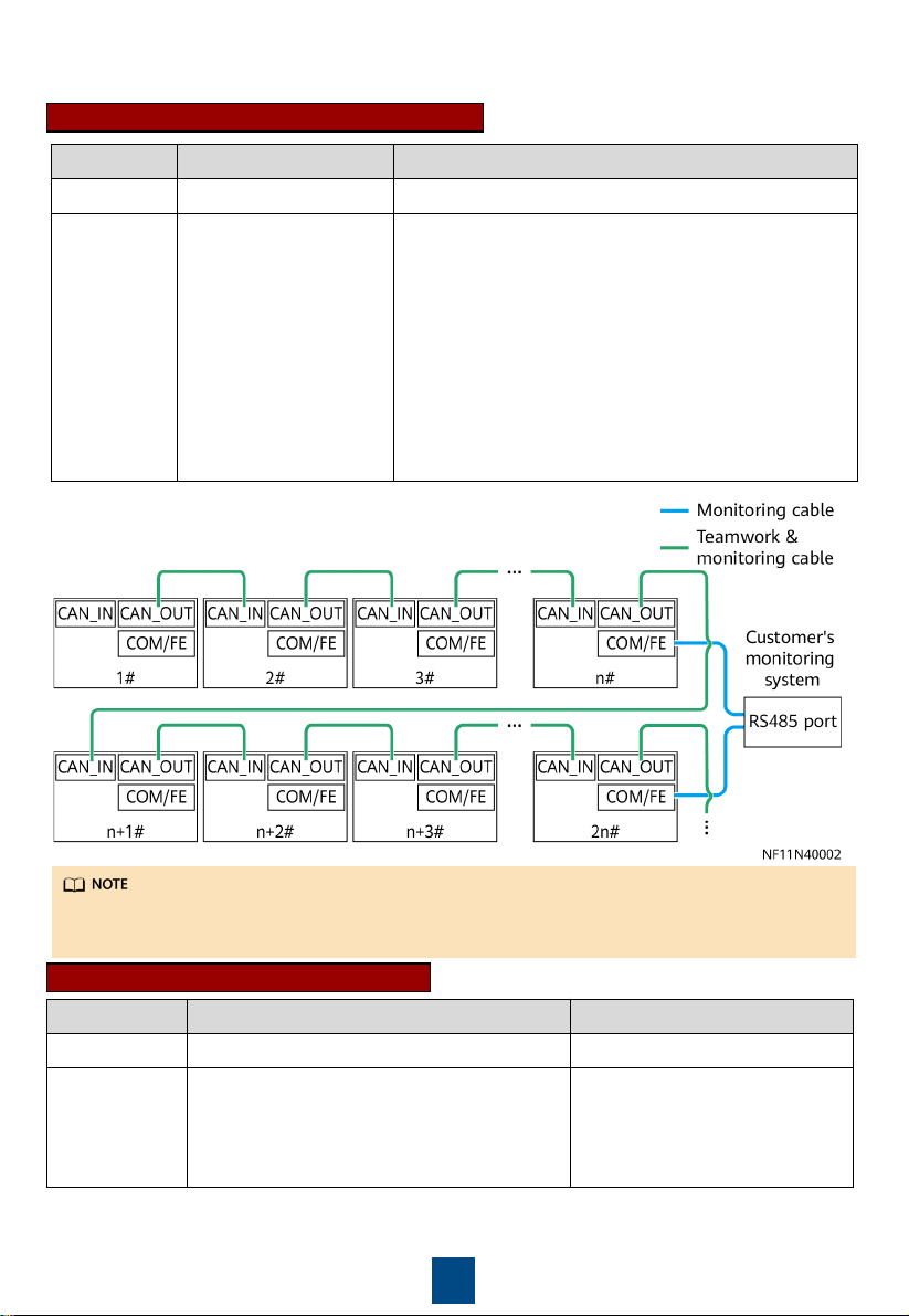
CAN teamwork + RS485 monitoring
2. Connect teamwork and monitoring communications cables.
Networking Teamwork Monitoring
Protocol CAN Modbus-RTU
Description One teamwork network
supports a maximum of
32 smart cooling
products. On the
Teamwork Settings
screen of the first and
last smart cooling
product controllers, set
Enable teamwork CAN
resistor to Yes.
It takes 3 x
n
seconds to collect data from
n
smart
cooling products. If the time required for the host to
collect data from all smart cooling products does not
meet the performance requirements, group the smart
cooling products.
• If devices are not grouped (
n
= 1), set RS485
monitoring grouping to Enable on the Modbus
Settings screen for each device.
• If devices are grouped (
n
> 1; recommended:
n
≤ 4),
set RS485 monitoring grouping to Enable on the
Modbus Settings screen for the device with the
COM/FE port connected.
Connect the COM/FE port on the main control module of the last smart cooling product in each
group to the RS485 port on the host.
CAN teamwork + FE monitoring
Networking Teamwork Monitoring
Protocol CAN Modbus-TCP/SNMP
Description One teamwork network supports a maximum
of 32 smart cooling products. On the
Teamwork Settings screen of the first and
last smart cooling product controllers, set
Enable teamwork CAN resistor to Yes.
-
13
Customers can purchase Huawei's switch and NetEco for the monitoring system.
(Optional) Installing the Cap (Applicable to Upflow Units)
4.4
• It takes two persons to install the cap using a 2 m step ladder.
• Before installing the cap, attach the thermal insulation foam in the accessories to the top
beam of the smart cooling product, and ensure that the reserved holes in the thermal
insulation foam are aligned with the holes in the beam. Check that the cap is intact and free
from scratches, that the sheet metal is not bent, and that the screws are secure.
1. Remove the cap front panel using a
Phillips screwdriver. Place the cap on the
top of the cabinet.
2. Secure the left and right sides of the cap using six
M5 screws and the front and rear of the cap using
four M5 screws.
3. Secure the cap front panel to the
frame, and adjust the angle of the
front panel blade.
14
Check Item Expected Result Actual Result
Cabinet
The cabinet is installed properly, without any tilt. The cabinet
is secured to the base by using bolts. The foreign matter inside
the cabinet, such as cable ties and stubs, has been cleaned up.
□
Passed
□
Failed
Fan
The fan of the downflow unit is lowered and secured to the
cabinet bottom plate. The fan has no foreign matter inside.
□
Passed
□
Failed
Water pan
The foreign matter inside the water pan is cleaned up.
□
Passed
□
Failed
Differential
pressure
switch
The cable ties are securely tightened around pressure tubes.
There is no foreign matter in pressure tubes. The pressure
tubes show no obvious bends.
□
Passed
□
Failed
Exhaust valve The exhaust valve is closed.
□
Passed
□
Failed
Drainage
valve
The drainage valve is closed.
□
Passed
□
Failed
Air filter
The air filter is correctly installed according to the airflow
direction marked on the frame.
□
Passed
□
Failed
Chilled water
valve
The chilled water valve and its actuator are securely installed.
The chilled water connector joints have been wrapped with
thermal insulation foam, and no metal or hose are exposed.
Cables are securely connected to the chilled water valve and
its actuator. Cables to the chilled water valve and its actuator
are secured. Check that the manual button on the actuator is
reset (the button bounces up).
□
Passed
□
Failed
5
Installation Verification
6
Equipment Power-On
1. Users are classified into admin and operator users, and admin users have more rights
than operator users. The preset password is 000001 for both types of users. For system
security purposes, change the preset password upon first login.
2. A login session automatically expires if no operation is performed in three minutes. It is
recommended that you tap at the lower right corner to manually log out after
operations are complete.
Power-On
6.1
1. Turn on the general switch, fan switch QF4. For a device that has two power inputs, turn on
both the active power switch QF1 and standby power switch QF2.
2. Power on the system.
• Select the language: English or Chinese.
• Select the date & time settings: date format, date, time, and time zone.
• On the home screen, tap Settings > System Settings > T/H Sensor to change
temperature and humidity control types or set points.
15
(Optional) Teamwork Settings
6.2
The table uses 8 smart cooling products in CAN teamwork as an example.
No.
Item
Teamwork
group no.
Teamwork
unit address
Teamwork
CAN
resistor
enable
Teamwork
function
Network
Total
number
of units
Number
of running
units
Rotation
function
Require
ment
control
1
1 1 Yes Enable
CAN
network
8
6 (2
standby)
Enable Enable
2
1 2 No Enable
CAN
network
/ / / /
...
... ... ... ...
CAN
network
... ... ... ...
8
1 8 Yes Enable
CAN
network
/ / / /
1. Teamwork group no.: A maximum of 32 smart cooling products can be connected in a
teamwork group and a maximum of four teamwork control groups can be connected in an
RS485 network. To increase the network management system (NMS) response speed, it is
recommended that one monitoring system should connect to one teamwork control group.
2. Teamwork unit address: In a teamwork control group, each smart cooling product address
must be unique, and the address of one smart cooling product must be 1 (master smart
cooling product).
3. Teamwork CAN resistor enable: After connecting smart cooling products 1 to 32 (determined
by cable routing sequence) in series, set the parameter to Yes for the first and last smart
cooling products in the teamwork control group, and retain default values (No) for other
smart cooling products.
4. Teamwork function: Indicates whether to disable or enable the teamwork function. If disabled,
a unit operates independently. If enabled, a unit operates in team with other units.
5. Network: The networking mode set on the screen must be consistent with the actual
networking mode. Otherwise, the teamwork control function will be unavailable.
6. Total number of units: Indicates the number of precision smart cooling products in a group.
The value is an integer ranging from 1 to 32.
7. Number of running units: Specifies the number of running NetCol8000-Cs in a group. The
value ranges from 1 to the number of NetCol8000-Cs in the group.
8. Rotation function: Enable the active and standby smart cooling products to work alternately.
This function is recommended when the heat load is even. When rotation is enabled, the
parameters for the rotation period and rotation time and forced rotation can be set based on
the customer's requirements.
9. When Requirement control is set to Enable, the master smart cooling product synchronizes
operating data (parameters such as the T/H control type, temperature set point, humidity set
point for the master smart cooling product) to the slave smart cooling product, and all the
precision smart cooling products in the group refer to the mode delivered by the master
smart cooling product. When Requirement control is set to Disable, the master smart
cooling product does not synchronize operating data to the slave smart cooling product, and
all the smart cooling products operate based on their own requirements, not referring to the
mode delivered by the master smart cooling product.
All teamwork control parameters can be set on the master smart cooling product. Only
Teamwork group No., Air conditioner address, Enable teamwork CAN resistor, Teamwork
function and Networking mode can be set on slave smart cooling products. Other parameters
of the slave units will be modified by the master unit synchronously.
16
a. On the home screen, choose Settings > Comm Settings > Modbus Settings. The value
should be consistent with that set on the NMS.
b. Set the communication address. The communication addresses of two smart cooling
products connecting to the same NMS must be unique.
c. Set RS485 monitoring grouping to Enable for the smart cooling product connected to
the host through the COM/FE port, and set this parameter to Disable for other smart
cooling products.
a. On the home screen, choose Settings > Comm Settings > IP Settings. The IP assigning
mode is set to Manual. Set IP address, Subnet mask, Gateway according to the actual
plan.
b. On the home screen, choose Settings > Comm Settings > Modbus Settings. The Link
mode can be set to Server and Client, Client, or Server. Set this parameter based on the
site requirements.
c. If Link mode contains Client, set Client encryption to Enable. Enter the actual IP address
of the EMS. When Client encryption is set to Enable, set NMS port number to 32907.
RS485 Monitoring Network Cable (Modbus-RTU Protocol)
FE Monitoring Network Cable (Modbus-TCP)
(Optional) Setting Communications Parameters
6.3
7
Commissioning
• The encryption mode must be the same as it on the NMS.
• For details about SNMP settings, see
NetCol8000-C(070, 130, 190) In-room Chilled Water
Smart Cooling Product User Manual
.
1. First startup flowchart
•
Download the Service Expert app from Huawei app store and runs on Android. Apply for
permission after downloading the app.
•
Except that the indoor fan item is mandatory, you can clear other commissioning items that
are not required.
•
If this is not the first startup, choose Maint > Wizard Startup to enter wizard startup.
•
If no humidifier or is configured, their commissioning items are not displayed.
Offline Boot or Online Boot can be selected for the first startup.

17
Offline Boot
Open the Service Expert app.
Tap Startup > Offline Activation on app.
After tapping Yes, the barcode and the
verification code are shown on the screen.
Tap Start on the home screen.
Enter Bar code and Verification code, and tap
Generate PWD.
Enter the generated startup password on the
screen of the smart cooling product.
Tap No on Wizard Startup screen to
exit wizard startup.
Tap Enter. The screen goes to Wizard Startup.
Tap Yes on Wizard Startup screen to
enter wizard startup.
Start
Open the Service Expert app, and Tap StartUp on the home screen
of the app.
Choose Link, and set the IP address, port, username, password, and
device address. Tap Login.
Choose Settings > Comm Settings > WIFI Settings on the home
screen and set the WiFi password.
Start
Insert the WiFi module to the USB port on the main control board.
Tap Login after the parameters are set.
Check that the device is started after you tap OK.
Connect WiFi by your mobile phone.
Online Boot
18
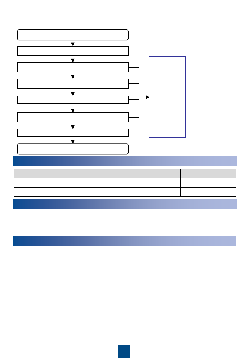
2. Wizard startup flowchart
Success
Success
Success
Success
(Optional) Electric heater commissioning
Chilled water valve commissioning
(Optional) Humidifier commissioning
Indoor fan commissioning
Commissioning
interrupted
(Handle the
fault by
referring to
the tips
displayed on
the home
screen.
Perform
wizard startup
after the
handling.)
Start
End
Confirm precautions and check items
Yes
No
No
Fail
Fail
Fail
Yes
Fail
Select commissioning items
8
Checking After Commissioning
Check Item Result
The controller has exited from the diagnostic mode.
□
Passed
□
Failed
The temperature and humidity are correctly set.
□
Passed
□
Failed
9
Power-Off
1. Tap Shutdown on the LCD home screen.
2. Turn off all switches on the smart cooling product.
3. If the smart cooling product will not be used over a long time, drain the water in the heat
exchanger or take antifreeze measures to avoid frost cracks.
Appendix 1: Precautions Against Adding Glycol
For details about adding glycol, refer to the
NetCol8000-C(070, 130, 190) In-room Chilled Water
Smart Cooling Product User Manual
.
To prevent the glycol solution from corroding pipes and the heat exchanging coil, corrosion
inhibitor should be mixed into the glycol solution. For details about the mixing schemes, consult
glycol experts.

Huawei Technologies Co., Ltd.
Huawei Industrial Base, Bantian, Longgang
Shenzhen 518129 People's Republic of China
www.huawei.com