Loading ...
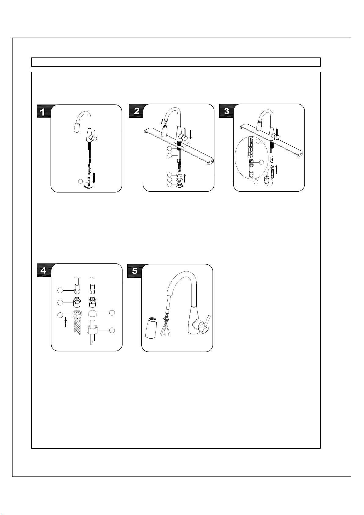
Important: after installation is
completed, turn on hot and cold water
supplies. Check for leaks. Pull the
hose assembly out of the spout and
remove the spray head by unscrewing
it from the hose counterclockwise. Be
sure to hold the end of the hose down
into the sink and turn the faucet on to
the warm position where it mixes hot
and cold water. Flush water lines for
one minute. Check for leaks.
Re-tighten any connections if
necessary, but do not overtighten.
Reinstall spray head by hand
tightening it back onto the spray hose.
Make connections to water lines with
3/8" female compression supply
hoses (1).
If additional hose length is needed,
attach included 1/2" MIP thread
adaptors (2) to supply hoses (1). Use
1/2" I.P.S. faucet connections (3) or
use coupling nuts (5) with 3/8"
O.D.ball-nose riser (4) to make
connections to water lines. Use
wrenches to tighten connections. Do
not overtighten.
Screw quick connect assembly to the free
end of pull-down hose. Align male fitting
(1) and tabs (2) on quick connector. Push
quick connector housing firmly upward
and snap onto receiving male fitting. Pull
down moderately to ensure connection
has been made. After connecting the
hose, attach weights (3) to hose at bottom
of loop to prevent hose from twisting and
return hose to proper position.
Retract pull-down hose (1) up through
faucet body, until the pull-down hose
fitting is flush with the bottom of shank
(2). Do not pull hose fitting past the
shank. Insert faucet body through the
hole in sink. From underneath sink,
install plastic washer (3), metal washer
(4) and nut (5) onto the mounting shank.
Do not overtighten.
Note: Do not feed the pull-down hose (1)
back down through the spout until step 3.
Shut off water supplies.
Before installation, remove quick
connect assembly (1) from the free end
of pull-down hose.
WARNING: Please carefully read and properly follow the instructions for installation found in this manual.
STEPS:
1
1
2
3
4
5
1
2
3
4
3
5
2
1
Ø 1 3/8" (Ø35mm)
Loading ...
Loading ...