Loading ...
Loading ...
Loading ...
35
INSTALLATION
Check the appliance is electrically safe when you have nished.
ArtNo.311-0028 - Burner head off
A
C
B
D
ArtNo.311-0030 - Burner head fitting
ArtNo.311-0029 - Burner base & head alignment
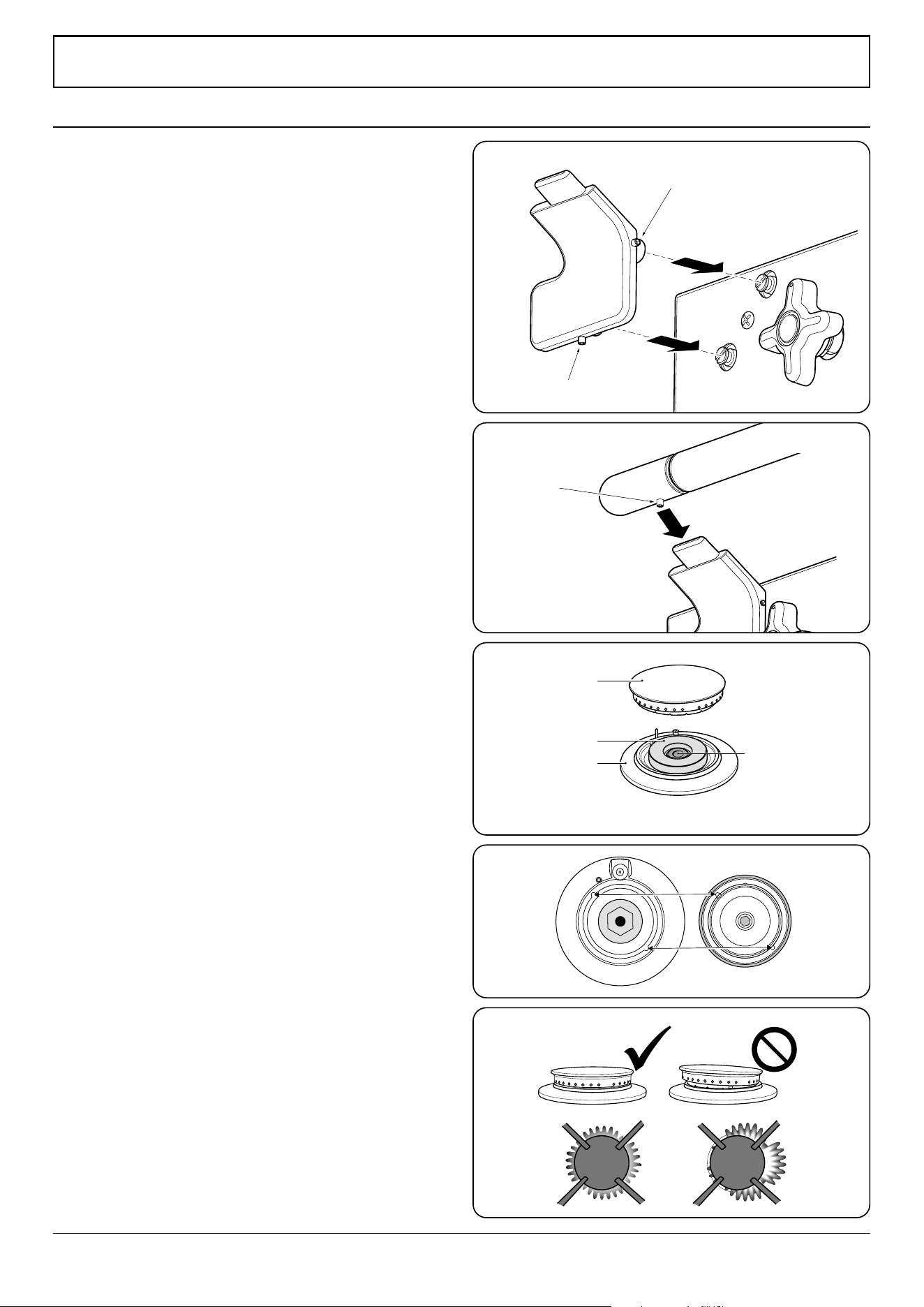
Fitting the handrail
1. Using the 2 mm Allen key supplied, loosen the two
retaining screws in the base and side of the handrail
support. Fit the handrail support onto the locating
bosses on the fascia (Fig. 12.1).
NOTE: The handle support should face upwards.
2. Push the support back against the fascia and tighten the
oneretaining screws. Repeat for the other side. Check
that each support is secure.
3. Locate the handrail onto the support tabs and, using
the 3 mm Allen key supplied, tighten the one retaining
screws in the bottom to secure (Fig. 12.2).
Fitting the Burner Heads
When tting the burner heads, ensure they locate properly
within the base (Fig. 12.3). If you look at the bottom of the
burner head you will see two ‘pips’; these t into the two
notches in the burner base (Fig. 12.4).
If the ame is distorted, check that the burner head is
correctly placed over the burner base (Fig. 12.5).
Fitting the Grates
Make sure that the grates are in the correct position and
sitting on the location pins.
Cooktop check
Refer to “Range Overview” and check operation of each
cooking zone in turn. Be sure to use pans of the correct size
and material.
Broiler check
Refer to “Range Overview” and check operation of the broiler
and that it heats up*.
Oven check
Refer to “Range Overview” and check the operation of both
ovens*. Check that the oven fans operate and the ovens heat
up.
* The cooling fan, located at the rear right hand side of the
cooktop, should operate with this function.
Customer care
Installer: Please complete your details in this guide, inform
the user how to operate the range and hand over the
instructions.
12. Final fitting and checks
Retaining screw
Retaining screw
Retaining
screw
Fig. 12.1
Fig. 12.2
Fig. 12.3
Fig. 12.4
Fig. 12.5
A – Burner head, B - Burner ring, C – Base, D – Venturi
Loading ...
Loading ...
Loading ...