
Loading ...
Loading ...
Loading ...
ENGLISH
WWW.STIEBEL-ELTRON-USA.COM DHC | 5
INSTALLATION
WATER CONNECTIONS
26_02_02_033126_02_02_1355
6. Water connections
1. All plumbing work must comply with national and applicable
state and local plumbing codes.
2. A pressure reducing valve must be installed if the cold water
supply pressure exceeds 150 psi (10 bar).
3. Make certain that the cold water supply line has been flushed
to remove any scale and dirt.
4. Install isolating valve in cold water line as shown in illus-
tration. This allows the unit to be isolated for maintenance
purposes.
5. Cold water connection (inlet) is on the right side of the unit,
hot water connection (outlet) is on the left side of unit.
Note
Excessive heat from soldering on copper pipes near the
DHC may cause damage.
6. Tankless water heaters such as the DHC are not required to
be equipped with a Temperature and Pressure Relief Valve
(T&P). If the local inspector will not pass the installation
without a T&P, it should be installed on the hot water outlet
side of appliance.
7. The DHC’s hot water outlet is designed for connection to cop-
per tubing, PEX tubing or a braided stainless steel hose with
a ½˝ NPT female tapered thread.
8. The plumbing on the cold water inlet side needs to be such
that it can easily be removed to allow access to the inlet filter
screen. The easiest way to achieve this is to use a stainless
steel braided hose connector. If soldering near the unit is
necessary, please direct the flame away from the housing of
the unit in order to avoid damage.
9. When all plumbing work is completed, check for leaks and
take corrective action before proceeding.
7. Electrical connection
!
WARNING:
Before beginning any work on the electric installation,
be sure that main breaker panel switches are “off”
to avoid any danger of electric shock. All mounting
and plumbing must be completed before proceed-
ing with electrical hook-up. Where required by local,
state or national electrical codes the circuits should be
equipped with a “ground fault interrupter”.
The unit must be properly grounded in accordance
with state and local codes, or in absence of such
codes, in accordance with national electric code or the
Canadian electric code. Failure to electrically ground
the product could result in serious personal injury or
death.
1. All electrical work must comply with national and applicable
state and local electrical codes.
2. The DHC should be connected to a properly grounded dedi-
cated branch circuit of proper voltage rating. In installa tions
with several DHC units, each unit requires an independent
circuit. Please refer to the technical data table for the correct
wire and circuit breaker size.
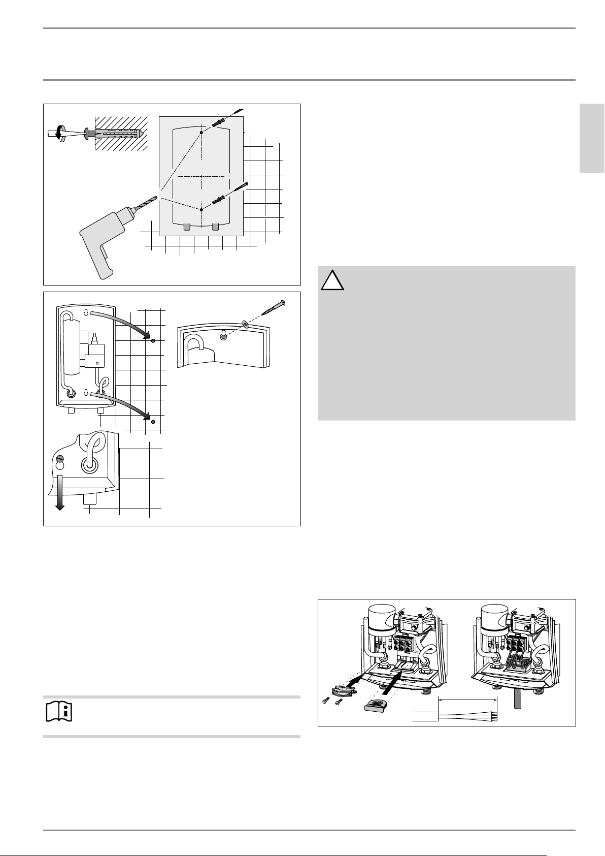
3. The wire must be fed through the rubber seal located be-
tween the hot and cold water connections. Then feed wires
through strain relief clamp and tighten clamp down on wire.
The “live” wires must be connected to the slots on the termi-
nal block marked N and L (DHC 3-1 only) or L and L (all other
versions). The ground wire must be connected to slot marked
with the ground symbol.
4. Reinstall plastic cover.
4˝ (100 mm)
26_02_02_0469
Loading ...
Loading ...
Loading ...