
Loading ...
Loading ...
Loading ...
i ,,,,,,,.,,,,,,,,,,,,,,,, ,,, ,,,,,,,, ............., ,
B. HAND FILING
Sharpen thesideplatesanddepthgaugesbyhandafter
every3rd to5thtimethePowerSharp_ Systemisused.
Items Required:
Gloves flat file
5/32" dia. file vise
file holder screwdriver
NOTE: If abrasive materials such as rocks, nails,
sand or dirt are contacted by the chain, the side
plates should be checked more often. Damage
to the cutters caused by abrasive materials
usually results in discoloration spots where the
chrome has been worn away. Cutter side plates -
should be filed until these spots are removed.
1. Stop the engine.
2. Adjust the chain for proper tension,See "Chain
Tension:'
3. Clamp the bar in a vise to hold the chain
stead','. Do not ctamp the chain.
NOTE: Work at the midpoint of the bar, mov-
ing'the chain forward with a screwdriver as
each cutter is filed.
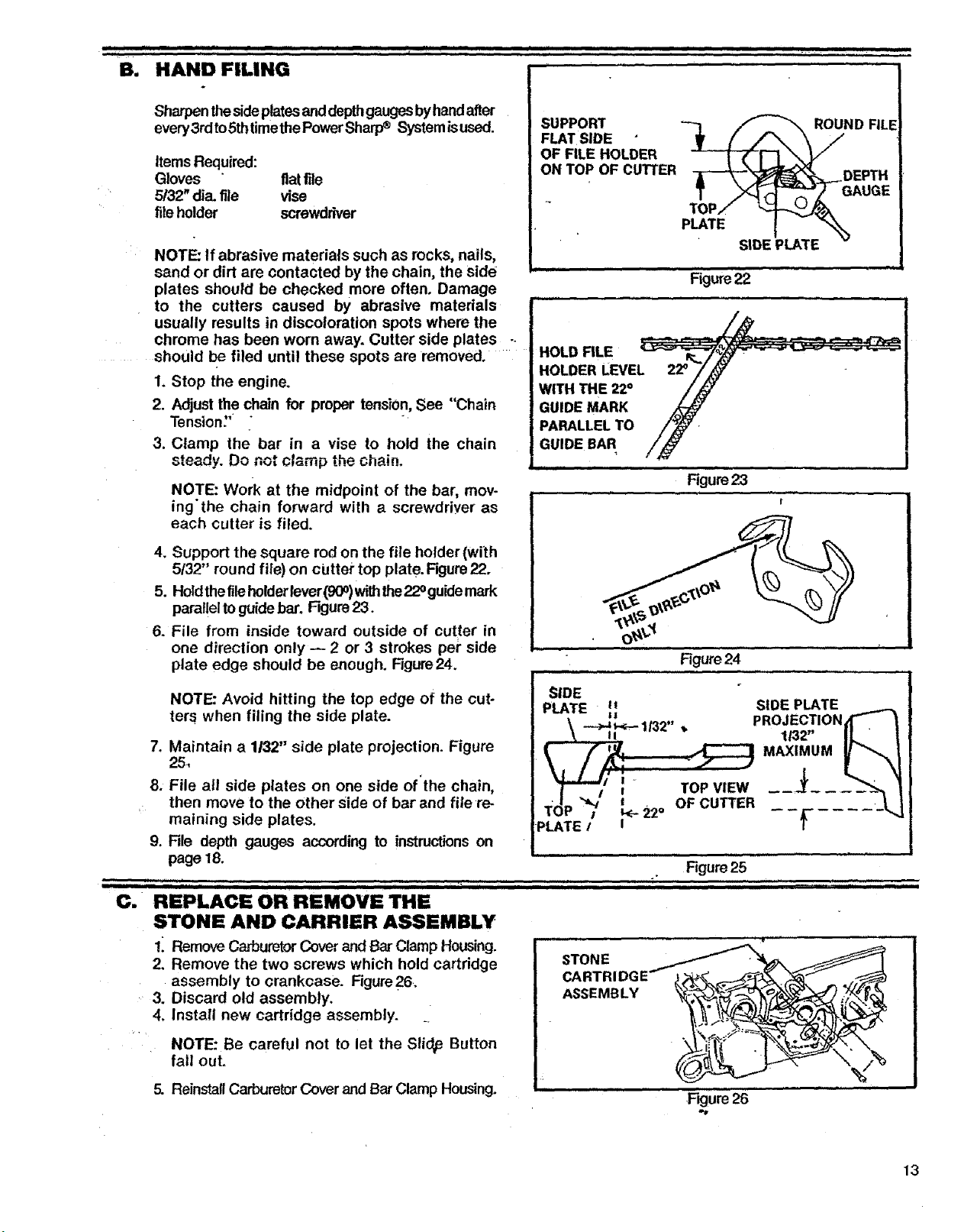
4. Support the square rod on the file holder (with
5/32" round file) on cUttei"top plate. Figure 22.
5. Holdthefileholder lever(900)withthe22° guidemark
parallelto guidebar. Figure23.
6. File from inside toward outside of cutter in
one direction only -- 2 or 3 strokes pep side
plate edge should be enough. Figure24.
NOTE: Avoid hitting the top edge of the cut-
ter_ when filing the side plate.
7. Maintain a 1/32" side plate projection. Figure
25,
8. File all side plates on one side of'the chain,
then move to the other Side of bar and file re-
maining side plates.
9. File depth gauges according to instructionson
page 18.
SUPPORT -_ iF-_ D FILl
FLAT SIDE ;_ L_ N
OF FILE HOLDER
ON TOP OF CUTI'ER _DEPTH
AUGE
• SIDE PLATE
, ,i i i,ii
Figure22
HOLD FILE
HOLDER LEVEL
WITH THE 22°
GUIDE MARK
PARALLEL TO
GUIDE BAR
Figure23
t
Figure 24
_IDE
SIDE PLATE
PLATE li
!
!
,, PROJECTION,_"- _
-ll32 " 132" IL t
"t-'-',' TOP .........
_,JI "-_" e OF CUTTER
TOP /l k_l 22° _ -- --
PLATE
c. "..... '...............
STONE AND CARRIER ASSEMBLY
. ,u , i
Figure25
ii iiiiii iii i lib '1IIIIIIIlflll III
!_ Remove Ca.,buretorCover and Bar Clamp Housing.
2. Remove the two screws which hold cartridge
assembly to crankcase. Figure26.
3. Discard old assembly.
4. Insta!l new cartridge assembly.
NOTE: Be careful not to let the Slid# Button
fall out.
5. Reinstall Carburetor Cover and Bar Clamp Housing.
I • I
ASSEMBLY
................,figure26"
13
Loading ...
Loading ...
Loading ...