Loading ...
Loading ...
Loading ...
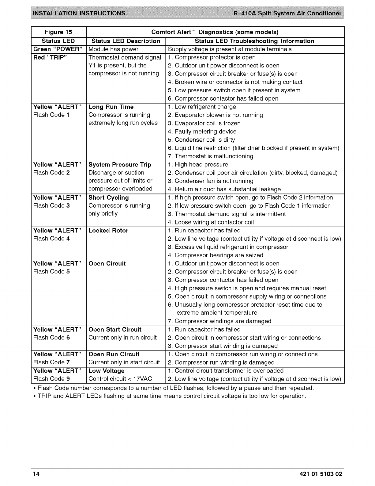
Figure 15
Status LED
Green "POWER"
Red "TRIP"
Yellow "ALERT"
Flash Code 1
Yellow "ALERT"
Flash Code 2
Yellow "ALERT"
Flash Code 3
Yellow "ALERT"
Flash Code 4
Yellow "ALERT"
Flash Code 5
Yellow "ALERT"
Flash Code 6
Yellow "ALERT"
Flash Code 7
Yellow "ALERT"
Flash Code 9
Comfort Alert TM
Status LED Description
Module has power
Thermostat demand signal
Y1 is present, but the
compressor is not running 3.
4.
5.
6.
Long Run Time 1
Compressor is running 2.
extremely long run cycles 3.
4.
5.
6.
7.
System Pressure Trip 1
Discharge or suction 2.
pressure out of limits or 3.
compressor overloaded 4.
Short Cycling 1
Compressor is running 2.
only briefly 3.
4.
Locked Rotor 1
2.
3.
4.
Open Circuit 1
2.
3.
4.
5.
6.
7.
Open Start Circuit 1
Current only in run circuit 2.
3.
Open Run Circuit 1
Current only in start circuit 2.
Diagnostics (some models)
Status LED Troubleshooting Information
Supply voltage is present at module terminals
1. Compressor protector is open
2. Outdoor unit power disconnect is open
Compressor circuit breaker or fuse(s) is open
Broken wire or connector is not making contact
Low pressure switch open if present in system
Compressor contactor has failed open
• Low refrigerant charge
Evaporator blower is not running
Evaporator coil is frozen
Faulty metering device
Condenser coil is dirty
Liquid line restriction (filter drier blocked if present in system)
Thermostat is malfunctioning
•High head pressure
Condenser coil poor air circulation (dirty, blocked, damaged)
Condenser fan is not running
Return air duct has substantial leakage
• If high pressure switch open, go to Flash Code 2 information
If low pressure switch open, go to Flash Code 1 information
Thermostat demand signal is intermittent
Loose wiring at contactor coil
•Run capacitor has failed
Low line voltage (contact utility if voltage at disconnect is low)
Excessive liquid refrigerant in compressor
Compressor bearings are seized
•Outdoor unit power disconnect is open
Compressor circuit breaker or fuse(s) is open
Compressor contactor has failed open
High pressure switch is open and requires manual reset
Open circuit in compressor supply wiring or connections
Unusually long compressor protector reset time due to
extreme ambient temperature
Compressor windings are damaged
•Run capacitor has failed
Open circuit in compressor start wiring or connections
Compressor start winding is damaged
•Open circuit in compressor run wiring or connections
Compressor run winding is damaged
Low Voltage 1. Control circuit transformer is overloaded
Control circuit < 17VAC 2. Low line voltage (contact utility if voltage at disconnect is low)
• Flash Code number corresponds to a number of LED flashes, followed by a pause and then repeated.
• TRIP and ALERT LEDs flashing at same time means control circuit voltage is too low for operation.
14 421 01 5103 02
Loading ...
Loading ...