This water heater complies with ANSI Z21.10.1-current
edition regarding the accidental or unintended ignition of
fl ammable vapors, such as those emitted by gasoline.
For Your Safety
AN ODORANT IS ADDED TO THE GAS USED
BY THIS WATER HEATER.
• Safety Instructions
• Installation
• Operation
PRINTED IN THE U.S.A 0213 PART NO. 322604-001
ALL TECHNICAL AND WARRANTY QUESTIONS: SHOULD BE DIRECTED TO THE LOCAL DEALER FROM WHOM THE WATER HEATER WAS PURCHASED.
IF YOU ARE UNSUCCESSFUL, CONTACT THE COMPANY LISTED ON THE RATING PLATE ON THE WATER HEATER.
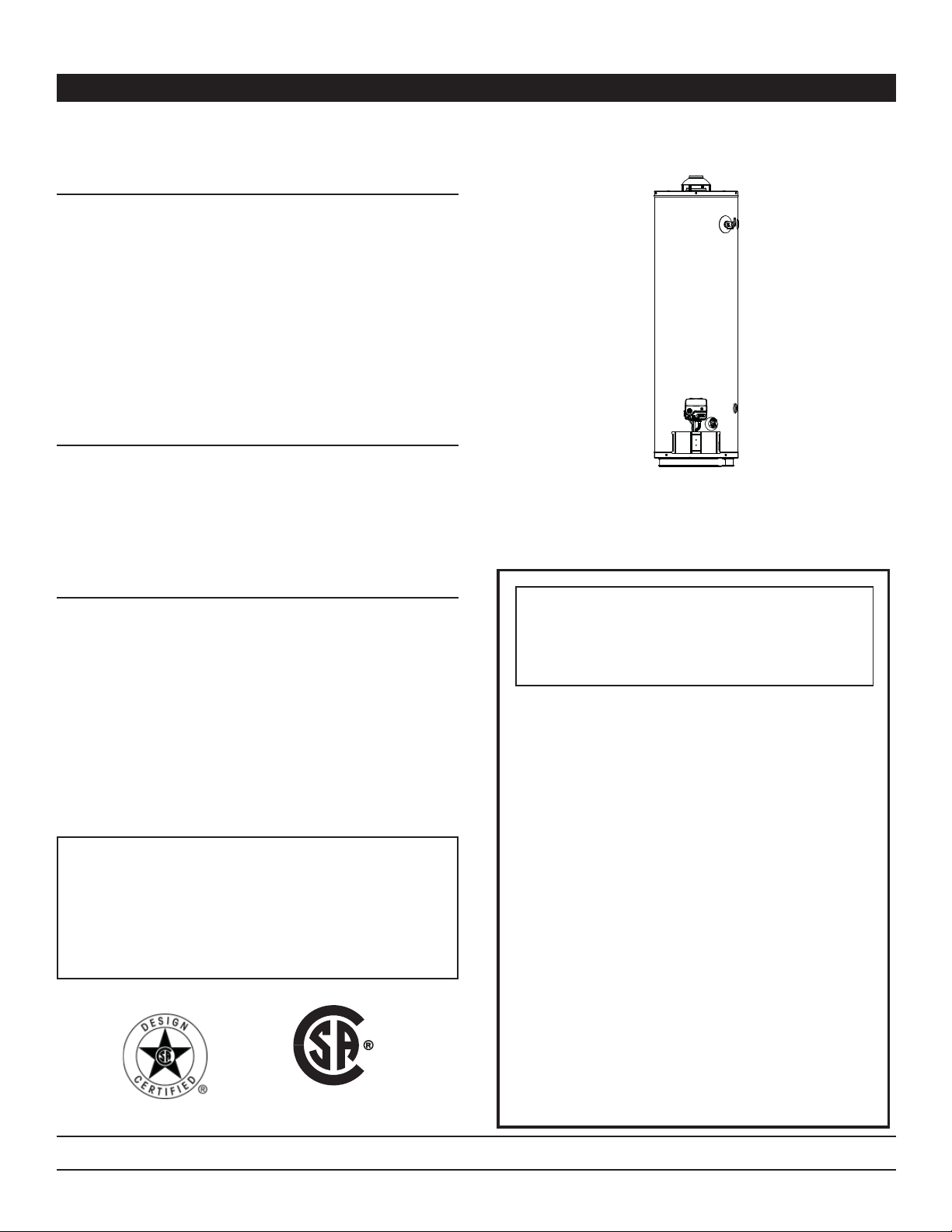
FVIR
GAS WATER HEATER
(FLAMMABLE VAPOR IGNITION RESISTANT)
FOR POTABLE WATER HEATING ONLY.
NOT SUITABLE FOR SPACE HEATING
FOR USE ONLY IN A MANUFACTURED
(MOBILE) HOME AND SHALL NOT BE INSTALLED IN THE
OCCUPIED SPACE OF THAT MOBILE HOME
SHIPPED SET FOR NATURAL GAS AND CONVERTIBLE TO
L.P. PROPANE GAS
(ALL PARTS INCLUDED)
— Do not store or use gasoline or other
flammable vapors and liquids in the
vicinity of this or any other appliance.
— WHAT TO DO IF YOU SMELL GAS
• Do not try to light any appliance.
• Do not touch any electrical switch;
do not use any phone in your
building.
• Immediately call your gas supplier
from a neighbor’s phone. Follow
the gas supplier’s instructions.
• If you cannot reach your gas
supplier, call the fire department.
— Installation and service must be
performed by a qualified installer,
service agency or the gas supplier.
WARNING: If the information in these
instructions is not followed exactly, a fire
or explosion may result causing property
damage, personal injury or death.
RESIDENTIAL GAS WATER HEATERS
Installation Instructions and Use & Care Guide
INSTALLER:
• AFFIX THESE INSTRUCTIONS TO OR ADJACENT TO
THE WATER HEATER.
OWNER:
• RETAIN THESE INSTRUCTIONS AND WARRANTY FOR
FUTURE REFERENCE. RETAIN THE ORIGINAL RECEIPT
AS PROOF OF PURCHASE.
WARNING: Gas leaks can not always be detected by
smell.
Gas suppliers recommend that you use a gas detector
approved by UL or CSA.
For more information, contact your gas supplier.
If a gas leak is detected, follow the “WHAT TO DO IF YOU
SMELL GAS” instructions.
• Care and Maintenance
• Troubleshooting
• Parts List
For Manufactured (Mobile) Homes
LOW LEAD
CONTENT
2
SAFE INSTALLATION, USE AND SERVICE
Flammable Vapors
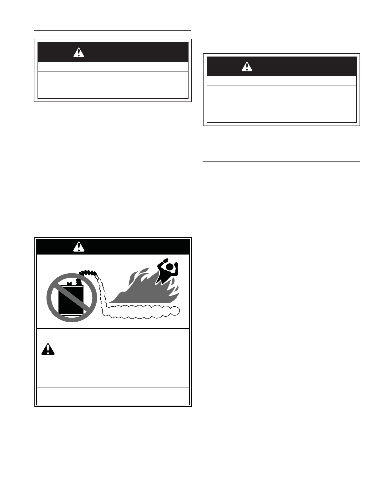
FLAMMABLES
FIRE AND EXPLOSION HAZARD
Can result in serious injury or death
Do not store or use gasoline or other
flammable vapors and liquids in the vicinity of this
or any other appliance. Storage of or use of
gasoline or other flammable vapors or liquids in the
vicinity of this or any other appliance can result in
serious injury or death.
Read and follow water heater warnings and instructions.
WARNING
Your safety and the safety of others is extremely important in the installation, use and servicing of this water heater.
Many safety-related messages and instructions have been provided in this manual and on your own water heater to warn you and
others of a potential injury hazard. Read and obey all safety messages and instructions throughout this manual. It is very important
that the meaning of each safety message is understood by you and others who install, use or service this water heater.
All safety messages will generally tell you about the type of hazard, what can happen if you do not follow the safety message
and how to avoid the risk of injury.
The California Safe Drinking Water and Toxic Enforcement Act requires the Governor of California to publish a list of substances known to
the State of California to cause cancer, birth defects, or other reproductive harm, and requires businesses to warn of potential exposure
to such substances. WARNING: This product contains a chemical known to the State of California to cause cancer, birth defects, or other
reproductive harm. This appliance can cause low-level exposure to some of the substances included in the act.
This product is certified to comply with a maximum weighted average of 0.25% lead content as required in some areas.
IMPORTANT DEFINITIONS
• Qualified Technician: A qualified technician must have ability equivalent to a licensed tradesman in the fields of plumbing, air
supply, venting, and gas supply, including a thorough understanding of the requirements of the National Fuel Gas Code as it
relates to the installation of gas fired water heaters. The qualified technician must also be familiar with the design features and
use of flammable vapor ignition resistant water heaters, and have a thorough understanding of this instruction manual.
• Service Agency: A service agency also must have ability equivalent to a licensed tradesman in the fields of plumbing, air supply,
venting and gas supply, including a thorough understanding of the requirements of the National Fuel Gas Code as it relates to the
installation of gas fired water heaters. The service agency must also have a thorough understanding of this instruction manual,
and be able to perform repairs strictly in accordance with the service guidelines provided by the manufacturer.
• Gas Supplier: The natural gas or propane utility or service who supplies gas for utilization by the gas burning appliances within
this application. The gas supplier typically has responsibility for the inspection and code approval of gas piping up to and including
the natural gas meter or propane storage tank of a building. Many gas suppliers also offer service and inspection of appliances
within the building.
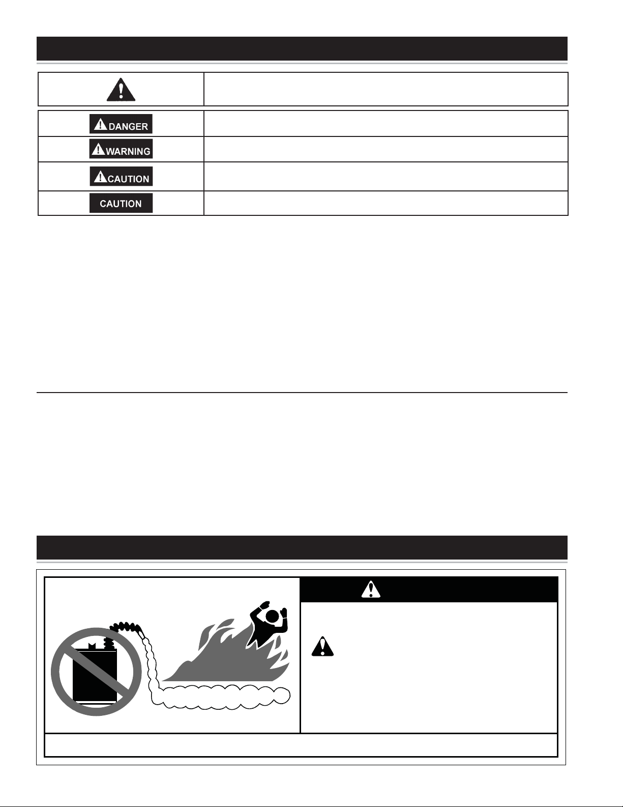
SAFETY PRECAUTIONS
This is the safety alert symbol. It is used to alert you to potential personal injury hazards.
Obey all safety messages that follow this symbol to avoid possible injury or death.
DANGER indicates an imminently hazardous situation which, if not avoided, will
result in death or injury.
WARNING indicates a potentially hazardous situation which, if not avoided, could result
in death or injury.
CAUTION indicates a potentially hazardous situation which, if not avoided, could result
in minor or moderate injury.
CAUTION used without the safety alert symbol indicates a potentially hazardous
situation which, if not avoided, could result in property damage.
3
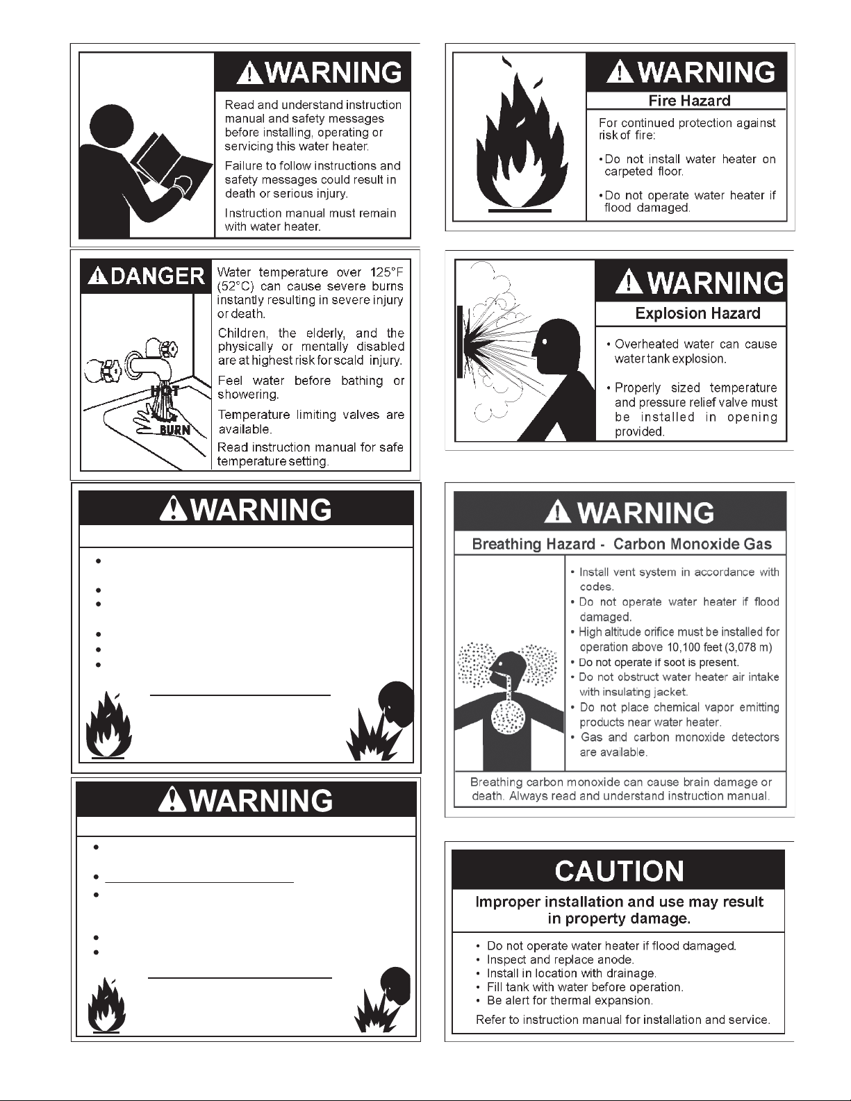
Fire or Explosion Harzard
Do not store or use gasoline or other flammable vapors and
liquids in the vicinity of this or any other appliance.
Avoid all ignition sources if you smell Natural or LP gas.
Do not expose water heater control to excessive gas
pressure.
Use only gas shown on rating plate.
Maintain required clearances to combustibles.
Keep ignition sources away from faucets after extended
period of non-use.
Read instruction manual before
installing, using or servicing
water heater.
Fire or Explosion Harzard
Hydrogen gas can be produced in a hot water system after
a period of non-use (generally two or more weeks).
Hydrogen gas is extremely flammable and can ignite.
To return hot water system to service, open a hot water
faucet in kitchen for several minutes before using electrical
appliances.
Do not smoke or have open flame near faucet while it is open.
Leave hot water faucet open until the sound of escaping
air stops.
After extended period of non-use,
purge gases from hot water system.

4
TABLE OF CONTENTS
SAFE INSTALLATION, USE AND SERVICE........................................................................................................................................ 2
SAFETY PRECAUTIONS .................................................................................................................................................................. 2-3
TABLE OF CONTENTS ........................................................................................................................................................................ 4
TYPICAL INSTALLATION ..................................................................................................................................................................... 5
INSTALLING YOUR GAS WATER HEATER ........................................................................................................................................ 6
Important Information About Your Water Heater ........................................................................................................................... 6
Consumer Information ................................................................................................................................................................... 6
Consumer Responsibilities ............................................................................................................................................................ 6
Unpacking the Water Heater ......................................................................................................................................................... 6
Location Requirements ................................................................................................................................................................. 7
Site Location............................................................................................................................................................................... 7-8
Securing Water Heater to Floor and Wall ...................................................................................................................................... 8
Clearances and Accessibility ......................................................................................................................................................... 8
Filling the Water Heater ................................................................................................................................................................. 9
GAS CONVERSION ........................................................................................................................................................................ 9-10
GAS SUPPLY ................................................................................................................................................................................ 11-12
Gas Requirements .......................................................................................................................................................................11
Gas Piping ....................................................................................................................................................................................11
Gas Pressure ...............................................................................................................................................................................11
Gas Pressure Testing ...................................................................................................................................................................11
LP Gas Only ................................................................................................................................................................................ 12
COMBUSTION AIR SUPPLY AND VENTILATION ........................................................................................................................ 13-14
Vent Pipe System ........................................................................................................................................................................ 13
Draft Hood Installation ................................................................................................................................................................. 13
Roof Jack Installation .................................................................................................................................................................. 13
Enclosure Installations ................................................................................................................................................................ 14
WATER SYSTEM PIPING ............................................................................................................................................................. 15-17
Piping Installation ........................................................................................................................................................................ 15
Water Piping Pressure Test ......................................................................................................................................................... 16
Closed System/Thermal Expansion ............................................................................................................................................ 16
Temperature and Pressure Relief Valve ...................................................................................................................................... 16
T&P Relief Valve and Pipe Insulation (Some Models) ................................................................................................................ 17
IMPORTANT INFORMATION ABOUT THIS WATER HEATER .......................................................................................................... 18
OPERATING YOUR WATER HEATER ......................................................................................................................................... 19-23
Lighting Instructions ............................................................................................................................................................... 19-20
Checking the Draft....................................................................................................................................................................... 21
Burner Flames ............................................................................................................................................................................. 21
Emergency Shut Down................................................................................................................................................................ 21
Water Temperature Regulation............................................................................................................................................... 21-22
Operational Conditions ........................................................................................................................................................... 22-23
MAINTENANCE OF YOUR WATER HEATER .............................................................................................................................. 24-29
Routine Preventive Maintenance ................................................................................................................................................ 24
Anode Rod Inspection ................................................................................................................................................................. 24
Temperature-Pressure Relief Valve Operation ....................................................................................................................... 24-25
Draining and Flushing ................................................................................................................................................................. 25
Replacement Parts ...................................................................................................................................................................... 25
External Inspection & Cleaning of the Base-Ring Filter .............................................................................................................. 25
Removing the Manifold/Burner Assembly .............................................................................................................................. 25-26
Removing the Burner from the Manifold/Burner Assembly ......................................................................................................... 26
Replacing the Pilot/Thermopile Assembly .............................................................................................................................. 26-27
Cleaning the Combustion Chamber and Flame-arrestor............................................................................
................................. 27
Replacing the Manifold/Burner Assembly............................................................................................................................... 27-28
Piezoelectric Igniter System ........................................................................................................................................................ 28
Testing the Igniter System ........................................................................................................................................................... 28
Removing and Replacing the
Gas Control Valve/Thermostat ............................................................................................................................................... 28-29
FVIR System Operational Checklist ............................................................................................................................................ 29
TROUBLESHOOTING CHART ..................................................................................................................................................... 30-31
PILOT LIGHT TROUBLESHOOTING FLOWCHART ......................................................................................................................... 32
STATUS LIGHT AND DIAGNOSTIC CODE TROUBLESHOOTING CHART ................................................................................ 33-34
REPAIR PARTS ILLUSTRATION ....................................................................................................................................................... 35
5
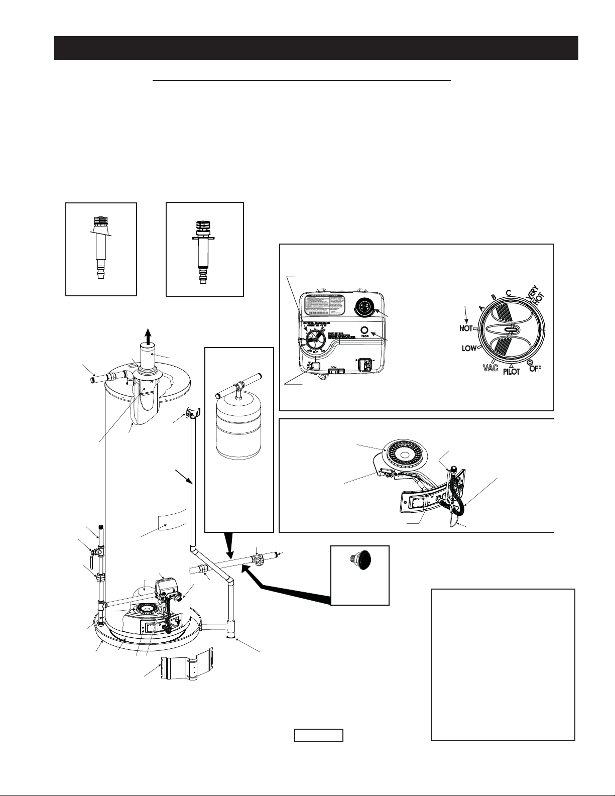
TYPICAL INSTALLATION
N
A
B
D
F
G
H
I
W
V
U
T
R
J
K
Q
M
L
E
P
Y
(U) MANIFOLD/BURNER ASSEMBLY
DISCHARGE PIPE
(DO NOT CAP
OR PLUG.)
(S) GAS CONTROL VALVE/
THERMOSTAT
DRAIN LINE MUST PASS
THROUGH THE STRUCTURAL
FLOOR AND DISCHARGE
EXTERNAL TO THE BUILDING
TO VENT
TERMINATION
(ROOF JACK)
VAC
Igniter
Gas Control/Temperature Knob
120°F
Mark
Temperatures shown are approximates and may vary.
Conversion
Fitting
MANIFOLD
TUBE
IGNITER WIRE
MAIN BURNER
PILOT TUBE
THERMOPILE
MANIFOLD DOOR
Status
Light
X
(Z) ROOF JACK**
(Z) ROOF JACK**
S
VACUUM RELIEF
VALVE*
INSTALL PER
LOCAL CODES
INSTALL THERMAL
EXPANSION TANK
IF WATER HEATER
IS INSTALLED IN
A CLOSED WATER
SYSTEM*
A Vent Pipe
B Draft Hood
C Anode (Not Shown)
D Hot Water Outlet
E Insulation
F Gas Supply Piping
G Manual Gas Shut-off Valve
H Ground Joint Union
I Sediment Trap
Z
GET TO KNOW YOUR WATER HEATER - GAS MODELS
J Inner Door
K Outer Door
L Union
M Inlet Water Shut-off Valve
N Cold Water Inlet
O Inlet Dip Tube (Not Shown)
P Temperature-Pressure Relief Valve
Q Rating Plate
S Gas Control Valve/Thermostat
T Drain Valve
U Manifold/Burner Assembly
V Flue
W Metal Drain Pan
X Piezo Igniter (bottom, Left-hand
Side of Gas Control Valve/Thermostat)
Y
Base-Ring Filter
Roof Jack (Various Models)
R Flue Baffle
3-12 PITCH OR LESS
5-12 PITCH OR LESS
* ALL PIPING MATERIALS TO BE
SUPPLIED BY CUSTOMERS.
** ROOF JACK NOT FURNISHED.
FIGURE 1.
* INSTALL IN ACCORDANCE
WITH LOCAL CODES.
* SEDIMENT TRAP
AS REQUIRED
BY LOCAL CODES.
* SECURE WATER HEATER TO FLOOR
AND WALL AS DESCRIBED IN THIS
MANUAL.
* INSTALLATION SHOULD COMPLY
WITH THE “ENCLOSURE
INSTALLATION” SECTION OF THIS
MANUAL.
6
Important Information About Your
Water Heater
This gas water heater was manufactured to voluntary safety
standards to reduce the likelihood of a flammable vapor
ignition incident. New technology used in meeting these
standards makes this product more sensitive to installation
errors or improper installation environments. Please review
the Installation Checklist section and make any required
installation upgrades or changes. IMPORTANT: This water
heater is shipped from the factory as a natural gas unit.
However, it may be converted to use LP gas. See the Gas
Conversion section for more information.
Consumer Information
• The installation must conform with these instructions and
the local code authority having jurisdiction. In the absence
of local and state codes, installations shall comply with
the “National Fuel Gas Code,” ANSI Z223.1 (NFPA 54)
-current edition.
Manufactured home manufacturers: The installation must
conform to “The Manufactured Home Construction and
Safety Standard, Title 24 CFR, Part 3280.”
These publications are available as follows:
The “National Fuel Gas Code” is available through The
Canadian Standards Association, 8501 East Pleasant Valley
Rd, Cleveland, Ohio 44131 or The National Fire Protection
Association, 1 Batterymarch Park, Quincy, MA 02269.
“The Manufactured Home Construction and Safety
Standard, Title 24 CFR, Part 3280” is available through
The U.S. Department of Housing and Urban Development
(HUD), 451 7th Street S.W., Washington, DC 20410.
Offices are also located throughout the United States.
Check your phone listings for the local authorities having
jurisdiction over your installation.
• For California installation, this water heater must be braced,
anchored, or strapped to avoid falling or moving during
an earthquake. See instructions for correct installation
procedures. Instructions may be obtained from California’s
Office of the State Architect, 1102 Q Street, Suite
5100, Sacramento, CA 95811. Instructions can also be
downloaded to your computer at
www.dsa.dgs.ca.gov/Pubs.
• Massachusetts Code requires this water heater to be
installed in accordance with Massachusetts 248-CMR 2.00:
State Plumbing Code and 248-CMR 5.00.
• Complies with 40 Ng/J NOx requirements of Texas and
most California AQM Districts.
Consumer Responsibilities
• Carefully plan the place where you are going to put the
water heater. Correct combustion, vent action, and vent
pipe installation are very important in preventing death from
possible carbon monoxide poisoning and fires. See Figures
1, 9, and 10.
Examine the location to ensure the water heater complies
with the installation instructions in this manual.
• Do not discard this manual. You or future users of this water
heater will need it for future reference.
• Service to the FVIR System should only be performed by
a qualified technician. Examples of a qualified technician
include: licensed plumbers, authorized gas company
personnel, and authorized service personnel.
• IMPORTANT: The manufacturer and seller of this water
heater will not be liable for any damages, injuries, or deaths
caused by failure to comply with the installation and operating
instructions outlined in this manual. If you lack the necessary
skills required to properly install this water heater, or you have
difficulty following the instructions, you should not proceed,
but have a qualified technician perform the installation of this
water heater.
• A rating plate identifying your water heater can be found on
the front of your water heater. When referring to your water
heater, always have the information listed on the rating plate
readily available. Retain your original receipt as proof of
purchase.
Unpacking the Water Heater
Excessive Weight Hazard
WARNING
Use two or more people to move and install the water heater.
Failure to do so can result in injury (including back injury).
IMPORTANT: Do not remove any permanent instructions,
labels, or the data label from either the outside of the water
heater or on the inside of water heater panels.
• Remove exterior packaging and place installation
components aside.
• Inspect all parts for damage prior to installation
and start-up.
• Completely read all instructions before attempting to
assemble and install this product.
• After installation, dispose of/recycle all packaging materials.
DANGER
Do not use this water heater with any gas other than the
one listed on the data plate unless the water heater has
been properly converted.
Refer to the “Gas Conversion” section of this manual to
convert from one gas to another. Failure to use the
correct gas can cause problems which can result in
death, serious bodily injury or property damage. If you
have any questions or doubts, consult your gas supplier
or gas utility company. Water heaters using bottled
propane or liquefied petroleum gas (LPG) are different
from natural gas models. A natural gas water heater will
not function safely on bottled propane or liquefied
petroleum gas (LPG) and a propane gas water heater will
not function safely on natural gas.
INSTALLING YOUR GAS WATER HEATER
7
Location Requirements
Carbon Monoxide Poisoning Hazard
WARNING
Do not install this water heater in any occupied space of the
manufactured (mobile) home.
Doing so can result in carbon monoxide poisoning and death.
The FVIR System is designed to reduce the risk of fl ammable
vapor-related fi res. The patented system protects your family by
trapping the burning vapors within the water heater combustion
chamber through the special fl ame-arrestor. The burning vapors
literally “burn themselves out” without escaping back into the
room. In the event of a fl ammable vapor incident, the FVIR
System disables the water heater by shutting off the gas supply
to the water heater’s burner and pilot, preventing re-ignition
of any remaining fl ammable vapors in the area. This will not
prevent a possible fi re/explosion if the igniter is depressed
and fl ammable vapors have accumulated in the combustion
chamber with the pilot light off. If you suspect a fl ammable
vapor incident has occurred, do not use this appliance. Do not
attempt to light this appliance, or depress the igniter button if you
suspect fl ammable vapors have accumulated inside or outside
the appliance. Immediately call a qualifi ed technician to inspect
the appliance. Water heaters subjected to a fl ammable vapors
incident will show a discoloration on the fl ame-arrestor and
require replacement of the entire water heater.
FIRE AND EXPLOSION HAZARD
Can result in serious injury or death
Do not store or use gasoline or other flammable
vapors and liquids in the vicinity of this or any other
appliance. Storage of or use of gasoline or other
flammable vapors or liquids in the vicinity of this or any
other appliance can result in serious injury or death.
Flammable Vapors
FLAMMABLES
Read and follow water heater warnings and instructions.
WARNING
Do not use or store fl ammable products such as gasoline,
solvents, or adhesives in the same room or area near the
water heater. If such fl ammables must be used, all gas burning
appliances in the vicinity must be shut off and their pilot lights
extinguished. Open the doors and windows for ventilation while
fl ammable substances are in use.
If fl ammable liquids or vapors have spilled or leaked in the area
of the water heater, leave the area immediately and call the fi re
department from a neighbor’s home. Do not attempt to clean
the spill until all ignition sources have been extinguished.
Fire or Explosion Hazard
WARNING
• Read instruction manual before installing, using or
servicing water heater.
• Improper use may result in fire or explosion.
• Maintain required clearances to combustibles.
Keep combustibles such as boxes, magazines, clothes, etc. away
from the water heater area.
Site Location
• DO NOT install this water heater in any occupied space
of the manufactured (mobile) home. There shall be no
openings between the occupied space of the manufactured
(mobile) home and the water heater enclosure.
• The water heater must be installed indoors and in a
vertical position on a level surface. Do not install in
bathrooms, bedrooms, or any occupied room normally
kept closed.
• Locate the water heater near the existing gas piping.
If installing a new gas line, locate the water heater to
minimize the pipe length and elbows.
• The water heater should be located in an area not subject
to freezing temperatures. Water heaters located in
unconditioned spaces may require insulation of the water
piping and drain piping to protect against freezing. The
drain and controls must be easily accessible for operation
and service. Maintain proper clearances as specified on
the rating plate.
• Do not locate the water heater near an air-moving device.
The operation of air-moving devices such as exhaust
fans, ventilation systems, clothes dryers, fireplaces,
etc., can affect the proper operation of the water heater.
Special attention must be given to conditions these
devices may create. Flow reversal of flue gases may
cause an increase of carbon monoxide inside of the
dwelling.
• If the water heater is located in an area that is subjected
to lint and dirt, it may be necessary to periodically clean
the base-ring filter and flame-arrestor (see Cleaning the
Combustion Chamber and Flame-arrestor).
• See also “Enclosure Installations” later in this manual.
NOTE: This water heater must be installed according to all local
and state codes or, in the absence of local and state codes,
the “National Fuel Gas Code”, ANSI Z223.1 (NFPA 54)-current
edition. Manufactured home manufacturers must conform with
“The Manufactured Home Construction and Safety Standard,
Title 24 CFR, Part 3280”.
8
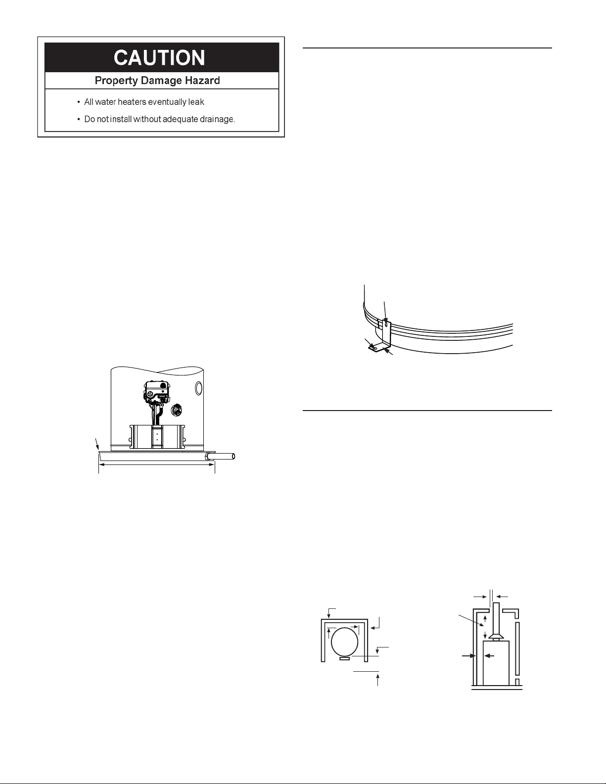
IMPORTANT: The water heater should be located in an area
where leakage of the tank or connections will not result in
damage to the area adjacent to the water heater or to lower
fl oors of the structure. Due to the normal corrosive action of
water, the tank will eventually leak after an extended period
of time. Also any external plumbing leak, including those from
improper installation, may cause early failure of the tank due to
corrosion if not repaired. If the homeowner is uncomfortable
with making the repair, a qualifi ed technician should be
contacted. A suitable metal drain pan should be installed under
the water heater as shown below, to help protect the property
from damage which may occur from condensate formation or
leaks in the piping connections or tank. The pan must limit the
water level to a maximum depth of 1-3/4” and be two inches
wider than the heater and piped to an adequate drain. NOTE:
The pan must not restrict combustion air fl ow. Locate the water
heater near an adequate drain (Figure 1). In cold climates, it is
recommended that the drain pipe be terminated at an adequate
drain inside the building. The piping should be at least 3/4” ID
and pitched for proper drainage.
METAL
DRAIN
PAN
AT LEAST 2” GREATER THAN THE
DIAMETER OF THE WATER HEATER.
PIPED TO AN
ADEQUATE DRAIN
SEE FIGURE 1
FIGURE 2.
Water heater life depends upon water quality, water usage,
water temperature and the environment in which the water
heater is installed. Water heaters are sometimes installed in
locations where leakage may result in property damage, even
with the use of a metal drain pan piped to a drain. However,
unanticipated damage can be reduced or prevented by a leak
detector or water shut-off device used in conjunction with a
piped metal drain pan. These devices are available from some
plumbing supply wholesalers and retailers, and detect and
react to leakage in various ways:
• Sensors mounted in the metal drain pan that trigger an
alarm or turn off the incoming water to the water heater
when water is detected.
• Sensors mounted in the metal drain pan that turn off the
water supply to the entire home when water is detected in
the drain pan.
• Water supply shut-off devices that activate based on the
water pressure differential between the cold water and hot
water pipes connected to the water heater.
• Devices that will turn off the gas supply to a gas water
heater while at the same time shutting off its water supply.
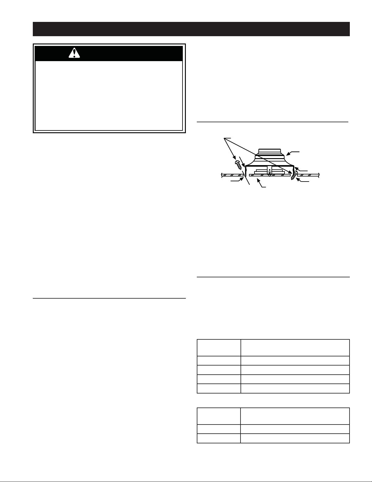
Securing Water Heater to Floor and Wall
The water heater must be secured to the fl oor and to the wall
of the enclosure as described below. See also “Enclosure
Installations.”
1. After properly locating the water heater, fasten it to the fl oor
with the brackets and screws that were provided
(Figure 3). Simply pre-drill each screw location in the
meta
l drain pan and water heater jacket with a 1/8” drill bit.
Because of installation variances, these brackets can be
located at any points around the circumference of the jacket.
However, they should be spaced apart at equal distances.
CAUTION: When making pilot holes in the water heater
itself, ensure that you drill only the outer jacket. Also,
to prevent leaks in the metal drain pan, seal each drill
location with a heavy bead of silicone sealant.
2. Secure the top of the water heater with the provided bracket
and screws or install other acceptable means of support
(e.g., support strap).
SCREW
SCREW
BRACKET
BOTTOM OF WATER HEATER
FIGURE 3.
Clearances and Accessibility
NOTE: Minimum clearances from combustible surfaces are
stated on the label adjacent to the gas control valve/thermostat
of the water heater. The water heater is certified for installation
on a combustible floor.
• IMPORTANT: If installing over carpeting, the carpeting
must be protected by a metal or wood panel beneath the
water heater. The protective panel must extend beyond the
full width and depth of the water heater by at least three
inches (76.2mm) in any direction; or if in an alcove or closet
installation, the entire floor must be covered by the panel.
• Figure 4 may be used as a reference guide to locate the
specific clearance locations. A minimum of 24 inches of front
clearance should be provided for inspection and service.
BACK
SIDES
TOP
VIEW
SIDES
VENT
FRONT
24” MINIMUM
FOR SERVICE
TOP
TO
CEILING
FIGURE 4.
9
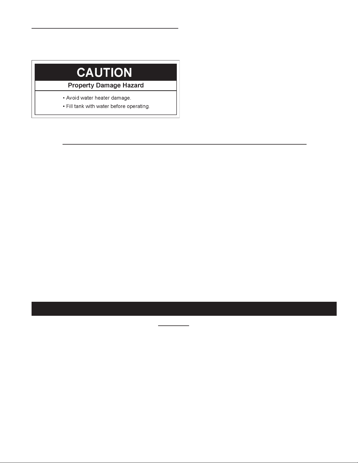
Filling the Water Heater
Never use this water heater unless it is completely full of
water. To prevent damage to the tank, the tank must be filled
with water. Water must flow from the hot water faucet before
turning “ON” gas to the water heater.
To fill the water heater with water:
• Close the water heater drain valve by turning the handle to
the right (clockwise). The drain valve is on the lower front
of the water heater.
• Open the cold water supply valve to the water heater.
NOTE: The cold water supply valve must be left open
when the water heater is in use.
• To ensure complete filling of the tank, allow air to exit by
opening the nearest hot water faucet. Allow water to run
until a constant flow is obtained. This will let air out of the
water heater and the piping.
• Check all water piping and connections for leaks.
Repair as needed.
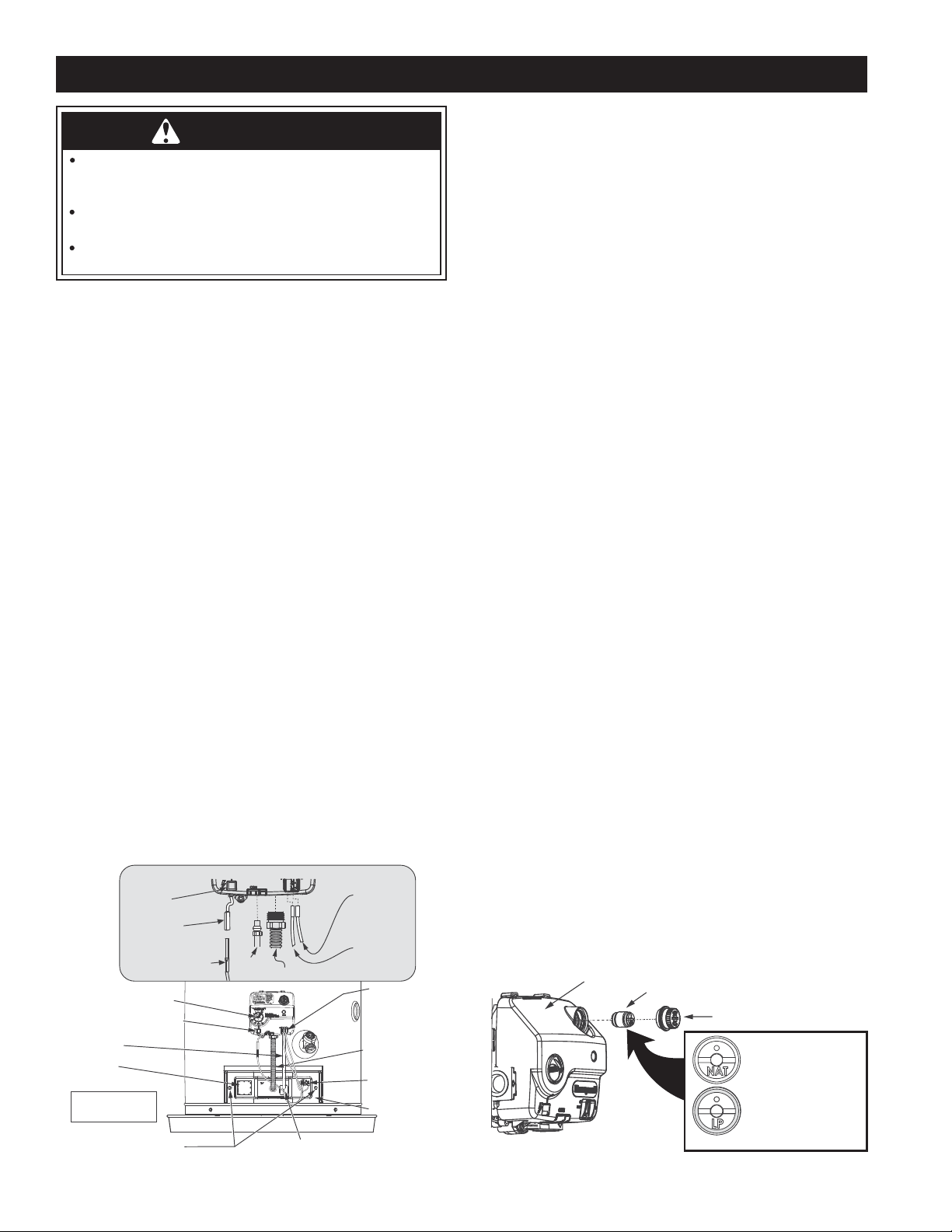
This water heater is originally shipped for use with Natural Gas but can be converted to LP (Propane) Gas by following the
instructions outlined below. To convert this water heater you must change both the conversion fitting in the gas control valve/
thermostat AND manifold/burner assembly (supplied). Both the gas valve and the manifold burner assembly must be correct for
the type of gas used. If you are unsure about converting this water heater to use a different type of gas, contact a qualified person
such as a plumber or your gas supplier.
1. Contact your gas company to determine the type of gas supplied to your home.
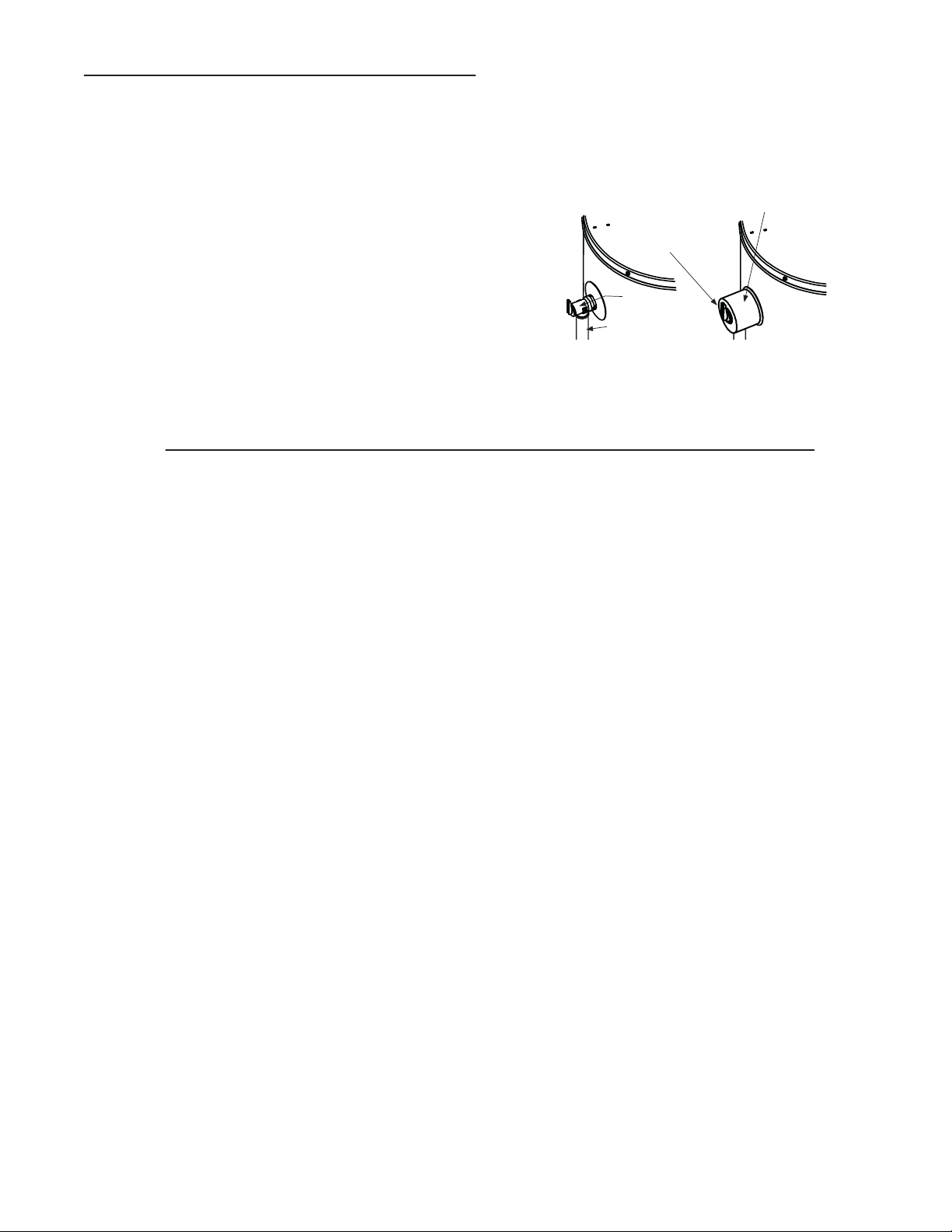
2. Check the setting of the conversion fitting in the gas control valve (see diagram).
3. Check the label on the manifold burner assembly door.
4. Make sure both the conversion fitting (figure 6) and the manifold burner assembly (see door label) are for the type of gas
supplied to your home.
5. If you are converting this water heater from Natural to LP or from LP to Natural follow these steps:
• Remove manifold burner assembly (see instructions on page 10)
• Install correct conversion manifold burner assembly (see instructions on page 10).
• Convert the gas control valve/thermostat to same type of gas (see instructions on page 10).
• Place sticker next to data plate showing the type of gas this water heater has been converted to.
GAS CONVERSION
10
GAS CONVERSION (Con’t)
For your safety, the following procedures should be
performed by a qualified technician as it involves
disconnection of gas piping and leak testing.
WARNING
Do not connect a natural gas water heater to an L.P.
gas supply.
Do not connect an L.P. gas water heater to a natural
gas supply.
FIGURE 6.FIGURE 5.
A. Remove the Manifold/Burner Assembly
1. Turn off the gas supply to the water heater at the manual
gas shut-off valve. This valve is typically located beside the
water heater. Note the position of the shut-off valve in the
open/on position, then proceed to turn it off.
2. On the lower front of the water heater, locate the gas control
valve/thermostat.
3. Turn the gas control/temperature knob to the “OFF” position.
With the unit shut-off, allow sufficient time for the water
heater to cool before performing any maintenance.
4. Remove the outer door.
5. Remove the two screws securing the installed manifold
door assembly to the combustion chamber (Figure 5).
6. Disconnect the following from the gas control valve/thermostat:
pilot tube, igniter wire, and manifold tube. See Figure 5.
7. Using needle nose pliers, disconnect the white and red
thermopile wires from the gas control valve/thermostat
(Figure 5).
8. Grasp the manifold tube and push down slightly to free the
manifold tube and pilot tube.
9. Carefully remove the manifold/burner assembly from the burner
compartment. NOTE: Be sure not to damage internal parts.
B. Convert the Gas Control Valve/Thermostat
1. Remove the cap (shown in Figure 6).
2. Remove the conversion fitting by turning it counter-clockwise
with a flathead screwdriver.
3. Thread the opposite end of the conversion fitting into the opening
by turning it clockwise, then tighten it with a flathead screwdriver.
a. LP GAS: If you are converting the unit to use LP gas
(propane), verify that “LP” is marked on the exposed end
of the fitting. “LP” must face outward (toward you.) See
Figure 6. If “NAT” faces outward, repeat step 2.
b. NATURAL GAS: If you are converting the unit to use
natural gas, verify that “NAT” is marked on the exposed
end of the fitting. “NAT” must face outward (toward you.)
See Figure 6. If “LP” faces outward, repeat step 2.
4. Replace the cap.
C. Install the Conversion Manifold/Burner
Assembly
1. Check the door gasket for damage or imbedded debris prior
to installation.
2. Inspect the view port for damage and replace as required.
3. Insert the conversion manifold/burner assembly into the
burner compartment, making sure that the tip of the manifold
tube engages in the slot of the bracket inside the combustion
chamber.
4. Inspect the door gasket and make sure there is no fiberglass
insulation between the gasket and the combustion chamber.
5. Replace the two screws that secure the manifold/burner
assembly door to the combustion chamber, then tighten
them securely. There should be no space between the
gasket part of the manifold door and the combustion
chamber. IMPORTANT: Do not operate the water heater
if the door gasket does not create a seal between the
manifold door and the combustion chamber.
6. Reconnect the manifold tube and pilot tube to the gas
control valve/thermostat (Figure 5). Do not cross-thread or
apply any thread sealant to the fittings. IMPORTANT: If you
were supplied with a new ferrule nut in a parts kit, follow
these steps to connect the pilot tube:
A.) Install the ferrule nut into the gas valve at the pilot tube
location, hand tight only. B.) Insert the pilot tube into the
ferrule nut until the tube bottoms out, then tighten the nut with
a 7/16” wrench until the crimp connection seals to the pilot tube.
C.) Continue to tighten until the nut is tight in the gas valve.
7. Connect the white and red thermopile wires to the gas
control valve/thermostat. See Figure 5.
8. Reconnect the igniter wire.
9. Turn the gas supply on and follow the Lighting Instructions.
10. With the main burner lit, check for leaks at the manifold and
pilot connections by brushing on an approved non-corrosive
leak detection solution. If such a solution is not available,
use a mixture of hand dish washing soap and water (one
part soap to 15 parts water). Bubbles forming indicate a
leak. Correct any leak found.
11. Verify proper operation; replace outer door.
VAC
MANIFOLD SCREW (2)
MANIFOLD COMPONENT BLOCK
MANIFOLD
DOOR
THERMAL
SWITCH
PILOT TUBE
MANIFOLD TUBE
VIEWPORT
THERMOPILE
WIRE
CONNECTIONS
PIEZO IGNITER BUTTON
GAS CONTROL/
TEMPERATURE KNOB
OUTER DOOR
NOT SHOWN
GAS CONTROL VALVE/THERMOSTAT CONNECTIONS
IGNITER
WIRE
RED WIRE
(LEFT SIDE)
PILOT
T
UBE MANIFOLD TUBE
IGNITER
BUTTON
IGNITER
LEAD
WIRE
WHITE
WIRE
(RIGHT
SIDE)
GAS CONTROL VALVE/THERMOSTAT
CONVERSION FITTING
CAP
NATURAL GAS:
“NAT” FACES OUTWARD
(TOWARD YOU).*
LP GAS:
“LP” FACES OUTWARD
(TOWARD YOU).*
* ORIENTATION MAY VARY. FITTING TO BE TIGHT.
11
Explosion Hazard
• Use a new CSA approved gas supply line.
• Install a shut-off valve.
• Do not connect a natural gas water heater to an
L.P. gas supply.
• Do not connect an L.P. gas water heater to a
natural gas supply.
• Failure to follow these instructions can result in
death, explosion, or carbon monoxide poisoning.
WARNING
Gas Requirements
IMPORTANT: Read the rating plate to be sure the water heater
is made for the type of gas you will be using in your home. This
information will be found on the rating plate located near the gas
control valve/thermostat. If the information does not agree with
the type of gas available, do not install or light. Call your dealer.
NOTE: An odorant is added by the gas supplier to the gas used
by this water heater. This odorant may fade over an extended
period of time. Do not depend upon this odorant as an indication
of leaking gas.
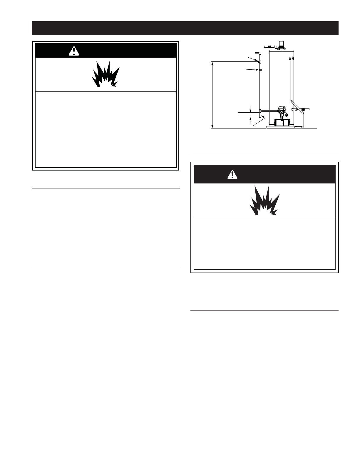
Gas Piping
The gas piping must be installed according to all local and state
codes or, in the absence of local and state codes, the “National Fuel
Gas Code”, ANSI Z223.1 (NFPA 54)-current edition. Manufactured
home manufacturers must conform with “ The Manufactured Home
Construction and Safety Standard, Title 24 CFR, Part 3280”.
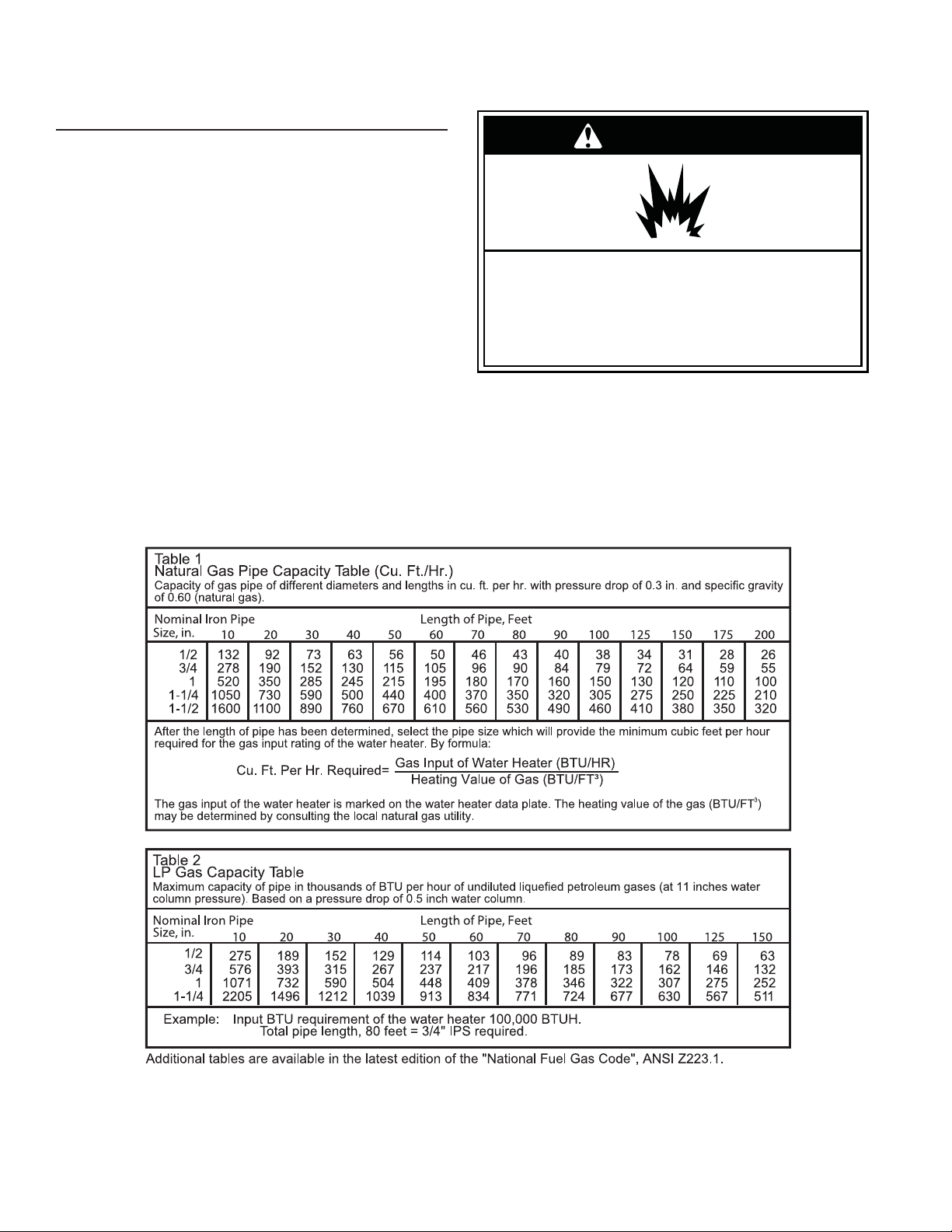
Tables 1 and 2 on the following page provide a sizing reference
for commonly used gas pipe materials. Consult the “National Fuel
Gas Code” for the recommended gas pipe size of other materials.
NOTE: Use pipe joint compound or tefl on tape marked as be-
ing resistant to the action of petroleum [Propane (L.P.)] gases.
(See Figure 7.)
1. Install a readily accessible manual shut-off valve in the gas
supply line as recommended by the local utility. Know the
location of this valve and how to turn off the gas to this unit.
2. Install a drip leg (if not already incorporated as part of
the water heater) as shown. The drip leg must be no less
than three inches long for the accumulation of dirt, foreign
material, and water droplets.
3. Install a ground joint union between the gas control valve/
thermostat and the manual shut-off valve. This is to allow
easy removal of the gas control valve/ thermostat.
4. Turn the gas supply on and check for leaks. Test all
connections by brushing on an approved noncorrosive
leak-detection solution. Bubbles will show a leak. Correct
any leak found.
GAS SUPPLY
CHECK WITH
LOCAL UTILITY
FOR MINIMUM HEIGHT
3” MINIMUM
DRIP LEG
GROUND
JOINT
UNION
MANUAL GAS
SHUT-OFF VALVE
FIGURE 7.
Gas Pressure
WARNING
Explosion Hazard
• Gas leaks can not always be detected by smell.
• Gas suppliers recommend that you use a gas
detector approved by UL or CSA.
• For more information, contact your gas supplier.
• If a gas leak is detected, follow the “What to do if you
smell gas” instructions on the cover of this manual.
IMPORTANT: The gas supply pressure must not exceed the maximum
supply pressure as stated on the water heater’s rating plate. The mini-
mum supply pressure is for the purpose of input adjustment.
Gas Pressure Testing
IMPORTANT: This water heater and its gas connection must be leak
tested before placing the appliance in operation.
• If the code requires the gas lines to be tested at a pressure
exceeding 14” W.C., the water heater and its manual shut-off
valve must be disconnected from the gas supply piping system
and the line capped.
• If the gas lines are to be tested at a pressure less than 14” W.C.,
the water heater must be isolated from the gas supply piping
system by closing its manual shut-off valve.
U.L. recognized fuel gas and carbon monoxide (CO) detectors are
recommended in all applications and should be installed using the
manufacturer’s instructions and local codes, rules and regulations.
NOTE: Air may be present in the gas lines and could prevent the pilot
from lighting on initial start-up. The gas lines should be purged of air
by a qualifi ed technician after installation of the gas piping system.
While purging the gas piping system of air, ensure that the fuel
is not spilled in the area of the water heater installation, or any
source of ignition. If the fuel is spilled while purging the piping
system of air follow the “WHAT TO DO IF YOU SMELL GAS”
instructions on the cover of this manual.
12
LP Gas Only
Liquefi ed petroleum gas is over 50% heavier than air and in the
occurrence of a leak in the system, the gas will settle at fl oor level.
Basements, crawl spaces, skirted areas under mobile homes
(even when ventilated), closets and areas below ground level will
serve as pockets for the accumulation of gas. Before lighting an
L.P. gas water heater, smell all around the appliance at fl oor level.
If you smell gas, follow the instructions as given in the warning on
the front page.
When your L.P. tank runs out of fuel, turn off the gas at all gas
appliances including pilot lights. After the tank is refi lled, all
appliances must be re-lit according to their manufacturer’s
instructions.
WARNING
Explosion Hazard
Have a qualified technician make sure that the L.P.
gas operating pressure does not exceed 13” water
column.
Failure to do so can result in death, explosion, or fire.
13
Carbon Monoxide Warning
The vent system must be installed according to all
local and state codes or, in the absence of local and
state codes, the “National Fuel Gas Code”, ANSI
Z223.1 (NFPA 54)-current edition. Manufactured home
manufacturers must comply with the “Manufactured
Home Construction and Safety Standard, Title 24 CFR,
Part 3280.”
Failure to do so can result in death, explosion, or
carbon monoxide poisoning.
WARNING
IMPORTANT: Air for combustion and ventilation must not
come from a corrosive atmosphere. Any failure due to
corrosive elements in the atmosphere is excluded from
warranty coverage.
The following types of installation (not limited to the following)
will require outdoor air for combustion due to chemical
exposure and may reduce but not eliminate the presence of
corrosive chemicals in the air:
• beauty shops
• photo processing labs
• buildings with indoor pools
• water heaters installed in laundry, hobby, or craft rooms
• water heaters installed near chemical storage areas
Combustion air must be free of acid-forming chemicals such
as sulfur, fl uorine, and chlorine. These elements are found
in aerosol sprays, detergents, bleaches, cleaning solvents,
air fresheners, paint, and varnish removers, refrigerants,
and many other commercial and household products. When
burned, vapors from these products form highly corrosive acid
compounds. These products should not be stored or used near
the water heater or air inlet.
Vent Pipe System
This water heater uses a non-direct, single-pipe vent system
to remove exhaust gases created by the burning of fossil fuels.
Air for combustion is taken from the outside (see “Enclosure
Installations”).
This water heater must be properly vented for the removal of
exhaust gases to the outside atmosphere. Correct installation
of the vent pipe system is mandatory for the proper and
effi cient operation of this water heater and is an important
factor in the life of the unit.
The vent pipe must be installed according to all local and state
codes or, in the absence of local and state codes, the “National
Fuel Gas Code”, ANSI Z223.1 (NFPA 54)-current edition.
Manufactured home manufacturers must conform with “The
Manufactured Home Construction and Safety Standard,
Title 24 CFR, Part 3280.” The vent pipe installation must not
be obstructed so as to prevent the removal of exhaust gases to
the outside atmosphere.
IMPORTANT: The use of vent dampers is not recommended
by the manufacturer of this water heater. Although some vent
dampers are certifi ed by CSA International, this certifi cation
applies to the vent damper device only and does not mean
they are certifi ed for use on this water heater.
COMBUSTION AIR SUPPLY AND VENTILATION
U.L. recognized fuel gas and carbon monoxide (CO) detectors are
recommended in all applications and should be installed using the
manufacturer’s instructions and local codes, rules, or regulations.
IMPORTANT:
• If you lack the necessary skills required to properly install
this venting system, you should not proceed, but get help
from a qualifi ed technician.
• DO NOT common vent this water heater with any other
appliance.
Draft Hood Installation
SHEET METAL SCREWS (FOUR PROVIDED)
DRAFT HOOD
LEGS
LEGS
SLOT
SLOT
JACKET TOP
INSTALL THE DRAFT HOOD WITH
THE FOUR SCREWS PROVIDED.
FIGURE 8.
Align the legs of the draft hood with the slots provided. Insert
the legs and secure the draft hood to the water heater’s top
with the four screws provided as shown in Figure 8. Do not
alter the draft hood in any way. If you are replacing an existing
water heater, be sure to use the draft hood supplied with this
water heater.
Roof Jack Installation
This water heater must have a properly-installed draft hood
and be connected to a listed roof jack that terminates to the
outdoors. The roof jack vent pipe must be secured to the draft
hood with sheet metal screws. (Roof jack not furnished.)
The following roof jack models are certified for use with this
water heater and are available from your water heater supplier:
Field Controls No. 987 for roof pitch of 5-12 or less:
KIT NUMBER MAXIMUM LENGTH BETWEEN
ROOF AND CEILING
9002964005 12”
9002965005 32”
9002966005 60”
9002967005 95”
White Metal Products 3RJ for roof pitch of 3-12 or less:
KIT NUMBER MAXIMUM LENGTH BETWEEN
ROOF AND CEILING
9007941005 14”
9007942005 30”
Install the roof jack according to its manufacturer’s instructions.
14
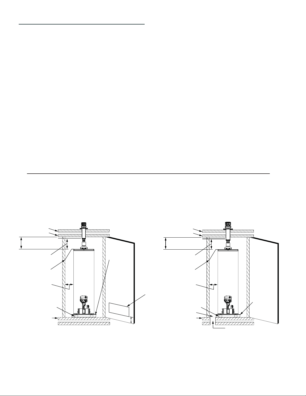
Enclosure Installation
Air for combustion and ventilation must not be supplied from
the occupied spaces of the manufactured (mobile) home.
IMPORTANT: The opening that provides outside air to your water
heater must have a minimum free area of 20 square inches.
Also, ensure that your installation complies with all applicable
code requirements.
The following methods may be used to provide sufficient
combustion and ventilation air to the water heater when it is
installed in the enclosure.
Method I (Figure 9)
Provide a single air opening in the exterior door of the enclosure.
The opening must have a minimum free area of 20 square inches.
The bottom of the opening must be within 6 inches from the
bottom edge of the door. Cover the opening with 1/4 inch wire
mesh screen or louvers.
Method II (Figure 10)
For enclosures with a solid exterior door, provide an air opening
in the fl oor. The opening must have a minimum diameter of 5
inches (20 square inches minimum free area) and be covered
with 1/4-inch wire mesh screen.
Also, if the manufactured home is skirted, an air intake opening
with a minimum free area of 32 square inches must be provided
in the skirt. Other gas fi red appliances in the home may require
additional free air openings. Consult the manufacturers for correct
sizing.
IMPORTANT:
• When using Method II, ensure that the drain pan does not
cover the air intake opening in the fl oor.
• A discharge line must be installed as described in the
“Temperature and Pressure Relief Valve” section.
• Do not obstruct the combustion and ventilation air openings.
• Do not use the enclosure as a storage area.
• Secure the water heater as described in “Securing Water Heater
to Floor and Wall.”
METAL
DRAIN PAN
ONE OPENING
IN DOOR *
PROTECTION:
1/4 IN. WIRE
MESH OR
LOUVERS
OPENING:
20 SQ. IN. MIN.
OUTSIDE
FRESH
AIR
6 INCHES MAX.
ABOVE BOTTOM
EDGE OF DOOR
* FREE AREA FOR AIR OPENING: 20 SQ. IN. MIN.
FLOOR
SECURE WATER HEATER
TO FLOOR WITH BRACKETS
AND SHEET METAL
SCREWS (PROVIDED)
MAINTAIN MIN.
CLEARANCES
SECURE TOP
TO WALL WITH
STRAP AND
SCREWS
MAINTAIN MIN.
CLEARANCE PER CODE
MAINTAIN MIN. CEILING
CLEARANCE PER LABEL
ON WATER HEATER
CEILING
ROOF
ROOF JACK
(NOT INCLUDED)
FIGURE 9.
ROOF JACK
(NOT INCLUDED)
MAINTAIN MIN. CEILING
CLEARANCE PER LABEL
ON WATER HEATER
MAINTAIN MIN.
CLEARANCE PER CODE
SECURE TOP
TO WALL WITH
STRAP AND
SCREWS
MAINTAIN MIN.
CLEARANCES
SECURE WATER HEATER
TO FLOOR WITH BRACKETS
AND SHEET METAL
SCREWS (PROVIDED)
FLOOR
AIR INTAKE
IMPORTANT: DRAIN PAN MUST
NOT BLOCK OR COVER AIR INTAKE
* FREE AREA FOR AIR OPENING: 20 SQ. IN. MIN.
FLOOR OPENING (5 IN. MIN. DIA.) *
1/4 IN. WIRE MESH PROTECTION
METAL
DRAIN PAN
ROOF
CEILING
Method I:
Door Opening
Method II:
Floor Opening
FIGURE 10.
15
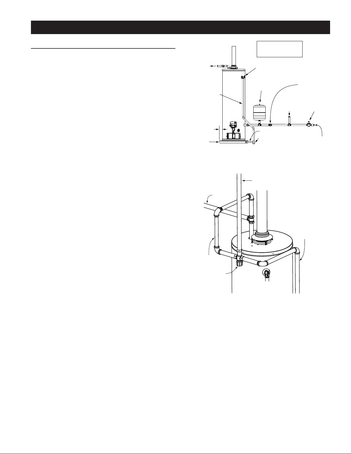
WATER SYSTEM PIPING
Piping Installation
Piping, fi ttings, and valves should be installed according to the
installation drawing (Figure 11). If the indoor installation area
is subject to freezing temperatures, the water piping must be
protected by insulation.
The water supply pressure should not exceed 80 psi. If this
occurs, a pressure reducing valve with a bypass may need to
be installed in the cold water inlet line. This should be placed
on the supply to the entire house in order to maintain equal hot
and cold water pressures.
IMPORTANT: Heat cannot be applied to the water fi ttings on
the heater as they may contain nonmetallic parts. If solder
connections are used, solder the pipe to the adapter before
attaching the adapter to the hot and cold water fi ttings.
IMPORTANT: Always use a good grade of joint compound and
be certain that all fi ttings are drawn up tight.
1. Install the water piping and fittings as shown in
Figure 11. Connect the cold water supply (3/4” NPT) to the
cold water inlet fitting. Connect the hot water supply (3/4”
NPT) to the hot water outlet fitting.
IMPORTANT: Some models may contain energy saving heat
traps to prevent the circulation of hot water within the pipes. Do
not remove the inserts within the heat traps.
2. The installation of unions in both the hot and cold water
supply lines is recommended for ease of removing the
water heater for service or replacement.
3. The manufacturer of this water heater recommends
installing a mixing valve or an anti-scald device in the
domestic hot water line as shown in Figure 12. These
valves reduce the point-of-use temperature of the water
by mixing cold and hot water and are readily available for
use.
4. If installing the water heater in a closed water system,
install an expansion tank in the cold water line as
specified under “Closed System/Thermal Expansion.”
5. Install a shut-off valve in the cold water inlet line. It
should be located close to the water heater and be easily
accessible. Know the location of this valve and how to
shut off the water to the heater.
6. A temperature and pressure relief valve must be installed
in the opening marked “Temperature and Pressure
(T & P) Relief Valve” on the water heater. A discharge line
must be added to the opening of the T&P Relief Valve.
Follow the instructions under “Temperature and Pressure
Relief Valve.”
7. After piping has been properly connected to the water
heater, remove the aerator at the nearest hot water
faucet. Open the hot water faucet and allow the tank to
completely fill with water. To purge the lines of any excess
air, keep the hot water faucet open for 3 minutes after a
constant flow of water is obtained. Close the faucet and
check all connections for leaks.
COLD WATER
INLET
PRESSURE
REDUCING
VALVE WITH
BYPASS
COLD WATER
SUPPLY
TO
FIXTURES
COLD WATER
INLET VALVE
(SHUT-OFF VALVE)
IN A CLOSED SYSTEM,
USE A THERMAL
EXPANSION TANK
TEMPERATURE AND PRESSURE (T&P)
RELIEF VALVE (OPTIONAL TOP T&P
RELIEF VALVE NOT SHOWN)
METAL
DRAIN PAN
1” MINIMUM
MASSACHUSETTS: INSTALL
A VACUUM RELIEF IN COLD
WATER LINE PER SECTION
19 MGL 142.
DISCHARGE PIPE
(DO NOT CAP
OR PLUG)
HOT WATER
OUTLET
PAN DRAIN LINE 3/4” ID MINIMUM
DRAIN LINE TERMINATES
EXTERNAL TO BUILDING
FIGURE 11.
FROM HOT
WATER
OUTLET
TEMPERED WATER
TO FIXTURES
MIXING VALVE
(SET TO 120°F)
FOLLOW THE MIXING
VALVE MANUFACTURER’S
INSTRUCTIONS
UNTEMPERED
HOT WATER
FROM COLD
WATER INLET
(BOTTOM, SIDE
OF TANK)
FIGURE 12.
Please note the following:
• The system should be installed only with piping that is
suitable for potable (drinkable) water such as copper,
CPVC, or polybutylene. This water heater must not be
installed using iron piping or PVC water piping.
• Use only pumps, valves, or fittings that are compatible with
potable water.
• It is recommend that only full flow ball or gate valves
are used in water piping installations. The use of valves
that may cause excessive restriction to water flow is not
recommended.
• Use only 95/5 tin-antimony or other equivalent solder. Any
lead based solder must not be used.
• Piping that has been treated with chromates, boiler seal, or
other chemicals must not be used.
• Chemicals that may contaminate the potable water supply
must not be added to the piping system.
16
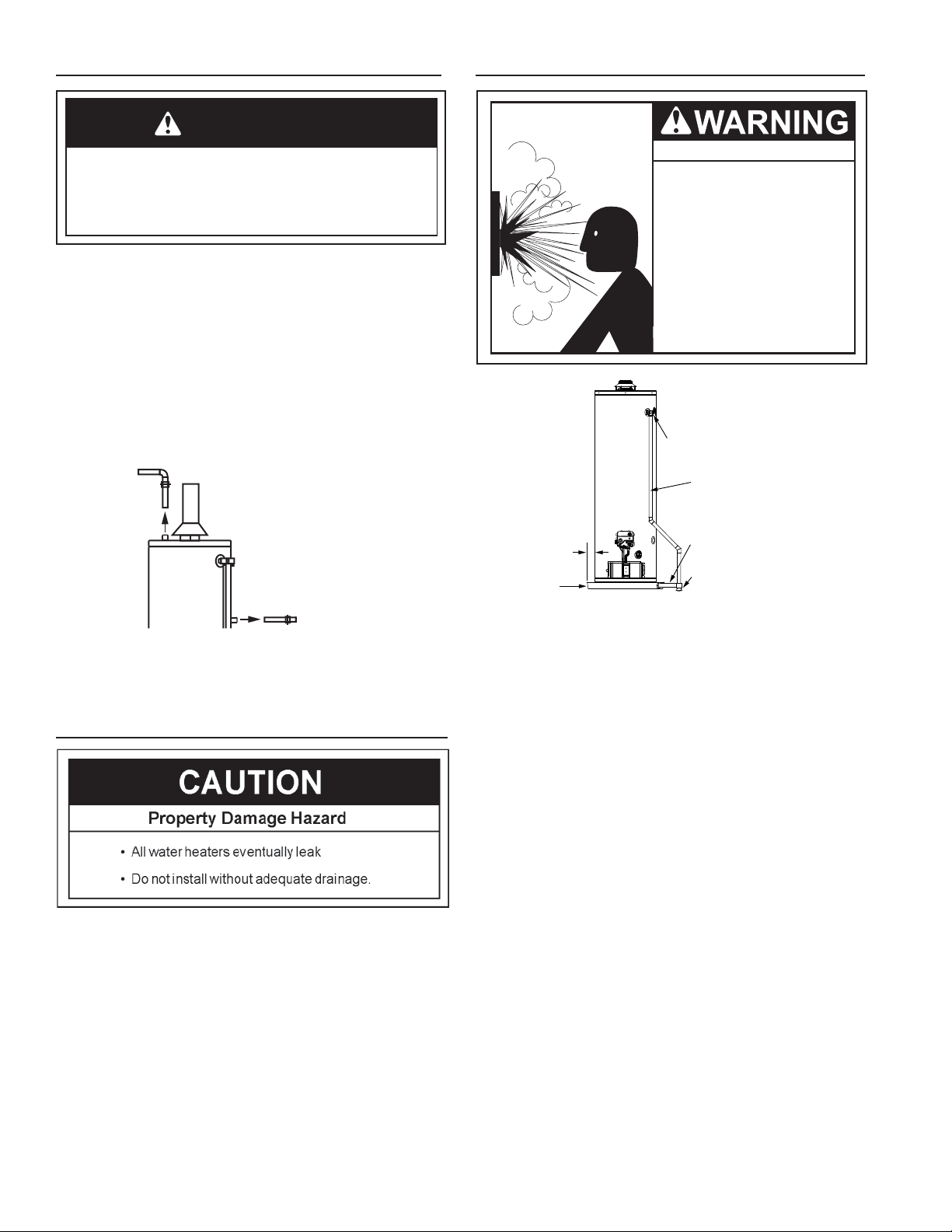
Temperature and Pressure Relief Valve
Explosion Hazard
7HPSHUDWXUHSUHVVXUHUHOLHIYDOYH
PXVWFRPSO\ZLWK$16,=-
&6$DQG$60(FRGH
3URSHUO\VL]HGWHPSHUDWXUH-
SUHVVXUHUHOLHIYDOYHPXVWEH
LQVWDOOHGLQRSHQLQJSURYLGHG
'RQRWSOXJEORFNRUFDSWKH
GLVFKDUJHOLQH
)DLOXUHWRIROORZWKLVZDUQLQJFDQ
UHVXOWLQH[FHVVLYHWDQNSUHVVXUH
VHULRXVLQMXU\RUGHDWK
TEMPERATURE AND PRESSURE (T&P)
RELIEF VALVE (OPTIONAL TOP T&P
RELIEF VALVE NOT SHOWN)
PAN DRAIN LINE
3/4” ID
MINIMUM
1” MINIMUM
DRAIN LINE TERMINATES
EXTERNAL TO BUILDING
METAL
DRAIN PAN
DISCHARGE PIPE
(DO NOT CAP OR PLUG)
FIGURE 14.
For protection against excessive pressures and temperatures,
a temperature and pressure relief valve must be installed in
the opening marked “T & P RELIEF VALVE.” (See Figure 14).
This valve must be design certifi ed by a nationally recognized
testing laboratory that maintains periodic inspection of the
production of listed equipment or materials as meeting the
requirements for Relief Valves for Hot Water Supply Systems,
ANSI Z21.22. The function of the temperature and pressure
relief valve is to discharge water in large quantities in the event
of excessive temperature or pressure developing in the water
heater. The valve’s relief pressure must not exceed the working
pressure of the water heater as stated on the rating plate.
IMPORTANT: Only a new temperature and pressure relief
valve should be used with your water heater. Do not use an old
or existing valve as it may be damaged or not adequate for the
working pressure of the new water heater. Do not place any
valve between the relief valve and the tank.
The Temperature & Pressure Relief Valve:
• Must not be in contact with any electrical part.
• Must be connected to an adequate discharge line.
• Must not be rated higher than the working pressure
shown on the rating plate of the water heater.
The Discharge Line:
• Must not be smaller than the pipe size of the relief valve or
have any reducing coupling installed in the discharge line.
• Must not be capped, blocked, plugged or contain any valve
between the relief valve and the end of the discharge line.
• Must pass through the structural floor and terminate
external to the building. In cold climates, it is
recommended that the discharge pipe be terminated at an
adequate drain inside the building.
• Must be capable of withstanding 250°F (121°C) without distortion.
• Must be installed to allow complete drainage of both the
valve and discharge line.
Water Piping Pressure Test
WARNING
If the water piping system is to be air pressure tested, the
water heater must be disconnected from the water piping
system. Failure to disconnect the water heater during air
pressure testing of the water piping system could result in
DEATH, SERIOUS BODILY INJURY, OR PROPERTY DAMAGE.
This section is only for the manufacturer installing the
water heater when the installation is to comply with H.U.D.
Standards. When testing the water ways, H.U.D. standards
state: “Water distribution system. All water piping in the water
distribution system shall be subjected to a pressure test. The
test shall be made by subjecting the system to air or water
at 100 psi for 15 minutes without loss of pressure. When air
pressure is used, the water heater shall not be connected
during the test.”
Closed System/Thermal Expansion
As water is heated, it expands (thermal expansion). In a closed
system, the volume of water will increase. As the volume of
water increases, there will be a corresponding increase in
water pressure due to thermal expansion. Thermal expansion
can cause premature tank failure (leakage). This type of failure
is not covered under the limited warranty. Thermal expansion
can also cause intermittent temperature-pressure relief valve
operation: water discharged from the valve due to excessive
pressure build up. The temperature-pressure relief valve is
not intended for the constant relief of thermal expansion. This
condition is not covered under the limited warranty.
A properly-sized thermal expansion tank should be installed
on all closed systems to control the harmful effects of thermal
expansion. Contact a plumbing service agency or your retail
supplier regarding the installation of a thermal expansion tank.
Air Pressure Testing
Hot Water
Outlet
When air testing,
remove the water lines
from the water heater.
Cold Water
Inlet
FIGURE 13.
17
T&P Relief Valve and Pipe Insulation (Some Models)
1. Locate the temperature and pressure relief valve on the water
heater (also known as a T&P relief valve). See Figure 15.
2. Locate the slit running the length of the T&P relief valve
insulation.
3. Spread the slit open and fit the insulation over the T&P relief
valve. See Figure 15. Apply gentle pressure to the insulation
to ensure that it is fully seated on the T&P Relief Valve. Once
seated, secure the insulation with duct tape, electrical tape,
or equivalent. IMPORTANT: The insulation and tape must not
block the discharge opening or hinder access to the manual
relief lever (Figure 15). Ensure a discharge pipe is installed
into the T&P valve discharge opening per the instructions in
this manual.
4. Locate the hot water (outlet) & cold water (inlet) pipes to the
water heater.
5. Locate the slit running the length of a section of pipe
insulation.
6. Spread the slit open and slip the insulation over the cold
water (inlet) pipe. Apply gentle pressure along the length of
the insulation to ensure that it is fully seated around the pipe.
Also, ensure that the base of the insulation is flush with the
water heater. Once seated, secure the insulation with duct
tape, electrical tape, or equivalent.
7. Repeat steps 5 and 6 for the hot water (outlet) pipe.
8. Add additional sections of pipe insulation as needed.
T&P Relief Valve
T&P Relief Valve
Drain Line
Manual Relief Lever
T&P Relief Valve Insulation
FIGURE 15.

18
IMPORTANT INFORMATION ABOUT THIS WATER HEATER
This gas water heater was manufactured to voluntary safety standards to reduce the likelihood of a fl ammable vapor ignition incident.
The new technology used in meeting these standards makes this product more sensitive to installation errors. Please review the
following checklist and make any required installation upgrades or changes.
Questions? Contact Residential Technical Assistance.
Installation Checklist
Water Heater Location
Water heater location is important and can affect system
performance. Please check the following:
□ Installation area free of corrosive elements and flammable
materials.
□ Centrally located with the water piping system (For new
installations). Located as close to the gas piping and vent
pipe system as possible.
□ Located indoors and in a vertical position. Protected from
freezing temperatures.
□ Proper clearances from combustible surfaces
maintained and not installed directly on a carpeted floor.
□ Provisions made to protect the area from water damage.
Metal drain pan installed and piped to an adequate drain.
□ Sufficient room to service the water heater. See
Clearances and Accessibility section of this manual.
□ Water heater not located near an air moving device.
□ Is the installed environment dirty (excessive amounts of
lint, dirt, dust, etc.)? If so, the base-ring filter located on
the bottom of the water heater will need to be cleaned
periodically. Refer to the “Maintenance of your Water
Heater” section of this manual for information on cleaning
the base-ring filter.
Combustion Air Supply and Ventilation
Check for suffi cient combustion air supply. Insuffi cient air for
the combustion of gas will result in the fl ame becoming “lazy”,
thereby allowing heat to build up in the combustion chamber.
This excessive heat will cause a thermal switch on the door
assembly to trip. Is the water heater installed in a closet or
other small, enclosed space? If so:
□ Are there openings for make-up air to enter and exit the
room/area?
□ Are the openings of sufficient size? Remember, if there
are other gas-fired or air-consuming appliances in the
same room, you need more make-up air. Refer to the
“Installing Your Gas Water Heater” and “Combustion Air
Supply and Ventilation” sections for specific requirements.
□ Make sure that fresh air is not taken from areas that con-
tain negative pressure producing devices such as exhaust
fans, dryers, fi replaces, etc.
□ Is there a furnace/air handler in the same room space as
the water heater? If so, has a return air duct system been
attached that exits the room? If so, check for leaks on the
air duct system. If no air duct system is present, correct
immediately by contacting a local Heating, Ventilation,
Air-Conditioning & Refrigeration (HVAC-R) authorized
service provider.
□ Use a fresh air supply that is free of corrosive elements
and flammable vapors.
□ Fresh air openings must be sized correctly with
consideration given to the blocking effect of louvers and
grilles.
Vent Pipe System
Check for proper drafting at the water heater draft hood. Refer
to the “Checking the Draft” section of this manual for the test
procedure. If the procedure shows insuffi cient draft is present,
please check the following:
□ Draft hood properly installed.
□ Vent connectors securely fastened with screws and
supported properly to maintain six inch clearance.
□ Vent connector made of approved material and sized
correctly.
□ Vent pipe system installed according to all local and state
codes or, in the absence of local and state codes, the
“National Fuel Gas Code”, ANSI Z223.1 (NFPA 54)-current
edition. Manufactured home manufacturers must conform
with the “Manufactured Home Construction and Safety
Standard, Title 24 CFR, Part 3280.”
□ Flue baffle properly positioned in the flue tube.
□ Check the vent system for restrictions/obstructions
and check the vent termination height. Refer to the
“Combustion Air Supply and Ventilation” section of this
water heater manual for specific requirements.
□ Recheck for sufficient combustion air supply.
Water System Piping
□ Temperature and pressure relief valve properly installed
with a discharge line run to an adequate drain and
protected from freezing.
□ All piping properly installed and free of leaks.
□ Heater completely filled with water.
□ Closed system pressure build-up devices installed.
□ Mixing valve (when applicable) installed per manufacturer’s
instructions (See “Water Temperature Regulation” section).
Gas Supply and Piping
□ Gas type is the same as that listed on the water heater
rating plate unless the water heater has been properly
converted. Refer to the “Gas Conversion” section of this
manual.
□ Gas line equipped with shut-off valve, union, and drip leg.
□ Use pipe joint compound or teflon tape marked as being
resistant to the action of petroleum [Propane (L.P.)] gases.
□ Adequate pipe size and approved pipe material.
□ An approved noncorrosive leak detection solution used
to check all connections and fittings for possible gas leaks.
Correct any leak found.
19
OPERATING YOUR WATER HEATER
Lighting Instructions
Read and understand these directions thoroughly before attempt-
ing to light or re-light the pilot. Make sure that the view port (sight
glass) is not missing or damaged. (See Figure 23.) Make sure
the tank is completely fi lled with water before lighting the pilot.
Check the rating plate near the gas control valve/thermostat for
the correct gas. Do not use this water heater with any gas other
than the one listed on the rating plate unless the water heater has
been properly converted. Refer to the “Gas Conversion” section
of this manual. If you have any questions or doubts, consult your
gas supplier or gas utility company.
WARNING
Explosion Hazard
Replace view port if glass is missing
or damaged.
Failure to do so can result in death,
explosion or fire.
Lighting the Pilot:
1. Read and follow the lighting instructions on the water heater’s
label.
2. Turn the Control Knob to Pilot. Press the Knob in fully and
hold it in. (The knob will travel in about 1/4-inch if it is set
to Pilot correctly.)
3. Click the Igniter button continuously for up to 90 seconds or
until the Status Light begins to blink.
If the Status Light does not begin to blink after 90 seconds,
STOP. Wait 10 minutes before attempting to relight the Pilot.
Repeat these steps 2-3 times, if necessary.
The circuitry in this gas valve requires that you wait 10 min-
utes between lighting attempts.
If the Status Light blinks, release the Control Knob and turn
it to the desired setting. (“Hot” is approximately 120°F).
If the Status Light Does Not Blink:
1. Wait 10 minutes before another lighting attempt.
2. If the Status Light did not blink, repeat the lighting procedure
by following the lighting instructions on the water heater’s
label. Remove the outer door. The Control Knob must be
set to Pilot and held in continuously while clicking the igniter
button (about once per second for up to 90 seconds). To
observe the Pilot, remove the outer door and look through
the view port (sight glass). See Figure 23.
3. Continue clicking the Igniter button (for up to 90 seconds)
until Pilot lights.
4. Once the Pilot is lit, continue to hold the Control Knob in until
the Status Light begins to blink.
5. Release Control Knob and set Knob to desired temperature
setting. (“Hot” is approximately 120°F.)
6. Replace the outer door.
If the Pilot Does Not Light:
1. Wait 10 minutes before another lighting attempt.
If the pilot does not light, the Igniter may not be sparking
or the unit may not be getting gas (or for a new installation,
there may still be air in the gas line).
Each time you click the igniter button, you should be able
to see the spark by looking through the view port. See
Figure 23. (You may have to darken the room lights to see
the spark.) You do not have to push the Control Knob in to
check the Igniter button. Simply look through the sight glass
while clicking the Igniter button and look for a spark. If you
can’t see a spark when the Igniter button is clicked, check
the wiring connections from the Igniter button and make sure
that they are tight.
2. If you see the Igniter spark, try relighting the pilot by following
the instructions on the water heater’s label. Ensure that the
gas supply is turned on. There may be air in the gas line,
and several lighting attempts may be needed to completely
fi ll the line with gas and successfully light the pilot.
If the Pilot Lights but the Status Light Does Not
Blink:
1. If the pilot lights, continue to hold the Control Knob in until
the Status Light blinks. If the pilot is lit and remains lit for 90
seconds and the Status Light still does not blink, the thermo-
pile connections may be loose, the thermal switch may need
to be reset, or the thermopile may be defective.
2. Remove the outer door.
3. Press the reset button on the thermal switch (Figure 23).
4. If switch clicks, it may have tripped. Do not light the Pilot
if fl ammable vapors are present. Check fl ame arrestor for
signs of discoloration (which could be caused by fl ammable
vapors). If the fl ame arrestor is discolored, do not attempt
to relight the Pilot. Have the water heater inspected by a
qualifi ed service technician.
5. Check the wiring connections from the thermopile
and the thermal switch to the gas control valve/ther-
mostat. Ensure that all wiring connections are tight.
See Figure 23.
6. Replace the outer door.
7. Wait 10 minutes and try to light the Pilot according to the
instructions on the water heater’s label.
8. While clicking the Igniter button continuously, the Control
Knob must be set to Pilot and held in until the Status Light
blinks. Once the Status Light blinks, release the Control Knob
and set the Knob to the desired temperature setting. (“Hot”
is approximately 120°F.)
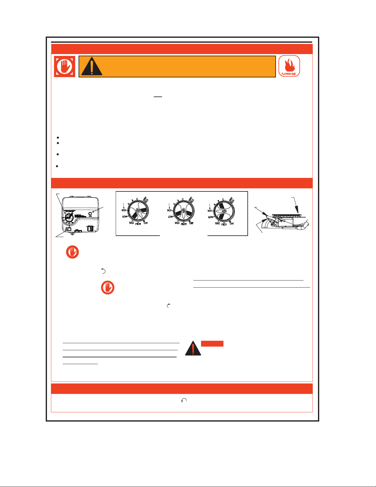
20
FOR YOUR SAFETY READ BEFORE LIGHTING
WARNING:
FLAMMABLE
If you do not follow these instructions exactly, a
fire or explosion may result causing property damage, personal
injury or loss of life.
LIGHTING INSTRUCTIONS
CONTROL KNOB
FIGURE 'A'
"OFF" POSITION
FIGURE 'B'
"PILOT" POSITION
FIGURE 'C'
"ON" POSITION
TO TURN OFF GAS TO APPLIANCE
FIGURE 'D'
GAS CONTROL
MAIN BURNER
THERMOPILE
PILOT
1. STOP! It is imperative that you read all safety
warnings before lighting the pilot.
2. Turn the gas control/temperature knob
counterclockwise to the "OFF" setting.
3. Wait ten (10) minutes to clear out any gas. If you then
smell gas, STOP! Follow “ B” in the safety
information above on this label. If you do not
smell gas, go to the next step.
4. Turn the gas control/temperature knob clockwise to
“ PILOT”. See Figure ‘B’.
5. Press the gas control/temperature knob all the way
in and hold it in. The knob should travel in about
1/4 inch (6.35 mm) if it is set to "PILOT" correctly.
While holding the gas control/temperature knob in,
click the igniter button continuously (about once a
second) for up to 90 seconds or until Status Light
begins to blink.
6. When the status light starts blinking, release the
gas control/temperature knob. Set the gas control/
temperature knob to the desired setting. See Figure ‘C’.
If the status light does not start blinking within 90
seconds, repeat steps 2 through 5 up to THREE (3)
times, waiting 10 minutes between lighting attempts.
The circuitry in this advanced gas valve requires
that you wait 10 minutes between lighting attempts.
If the status light turns solid, release the gas
control/temperature knob and repeat steps 2 through 5
(waiting 10 minutes before attempting to relight the pilot).
If the status light does not start blinking after three
lighting attempts, turn the gas control/temperature knob
to "OFF" and call a qualified service technician or your
gas supplier.
DANGER: Hotter water increases the risk of scald
injury. Consult the instruction manual before
changing temperature.
Refer to the Lighting Instructions in the Installation
Manual for more detailed troubleshooting
information.
1. Turn the gas control/temperature knob counterclockwise to the "OFF" setting. The status light will stop blinking and stay
on for a short time after the water heater is turned off. See Figure ‘A’.
VAC
Gas Control/Temperature Knob
Status
Light
Igniter
120°F
Mark
120°F
Mark
120°F
Mark
120°F
Mark
120°F
Mark
120°F
Mark
BEFORE LIGHTING: ENTIRE SYSTEM MUST BE FILLED WITH WATER AND AIR PURGED FROM ALL LINES
A.
C.
D.
B.
BEFORE LIGHTING
smell all around the appliance
area for gas. Be sure to smell next to the floor
because some gas is heavier than air and will
settle on the floor.
WHAT TO DO IF YOU SMELL GAS
Do not try to light any appliance.
Do not touch any electric switch; do not use any
phone in your building.
Immediately call your gas supplier from a neighbor's
phone. Follow the gas supplier's instructions.
If you cannot reach your gas supplier, call the fire
department.
Use only your hand to push in or turn the gas control
knob. Never use tools. If the knob will not push in or
turn by hand, don't try to repair it, call a qualified
service technician. Force or attempted repair may
result in a fire or explosion.
Do not use this appliance if any part has been under
water. Immediately contact a qualified installer or
service agency to replace a flooded water heater.
Do not attempt to repair the unit! It must be replaced!
This appliance has a pilot which is lit by a piezo-
electric spark gas ignition system. Do not open
the inner door of the appliance and try to light
the pilot by hand.
DO NOT USE THIS APPLIANCE IF THERE HAS
BEEN AN IGNITION OF VAPORS. Immediately
call a qualified service technician to inspect the
appliance. Water heaters subjected to a
flammable vapors ignition will show a
discoloration on the air intake grid and require
replacement of the entire water heater.
E.
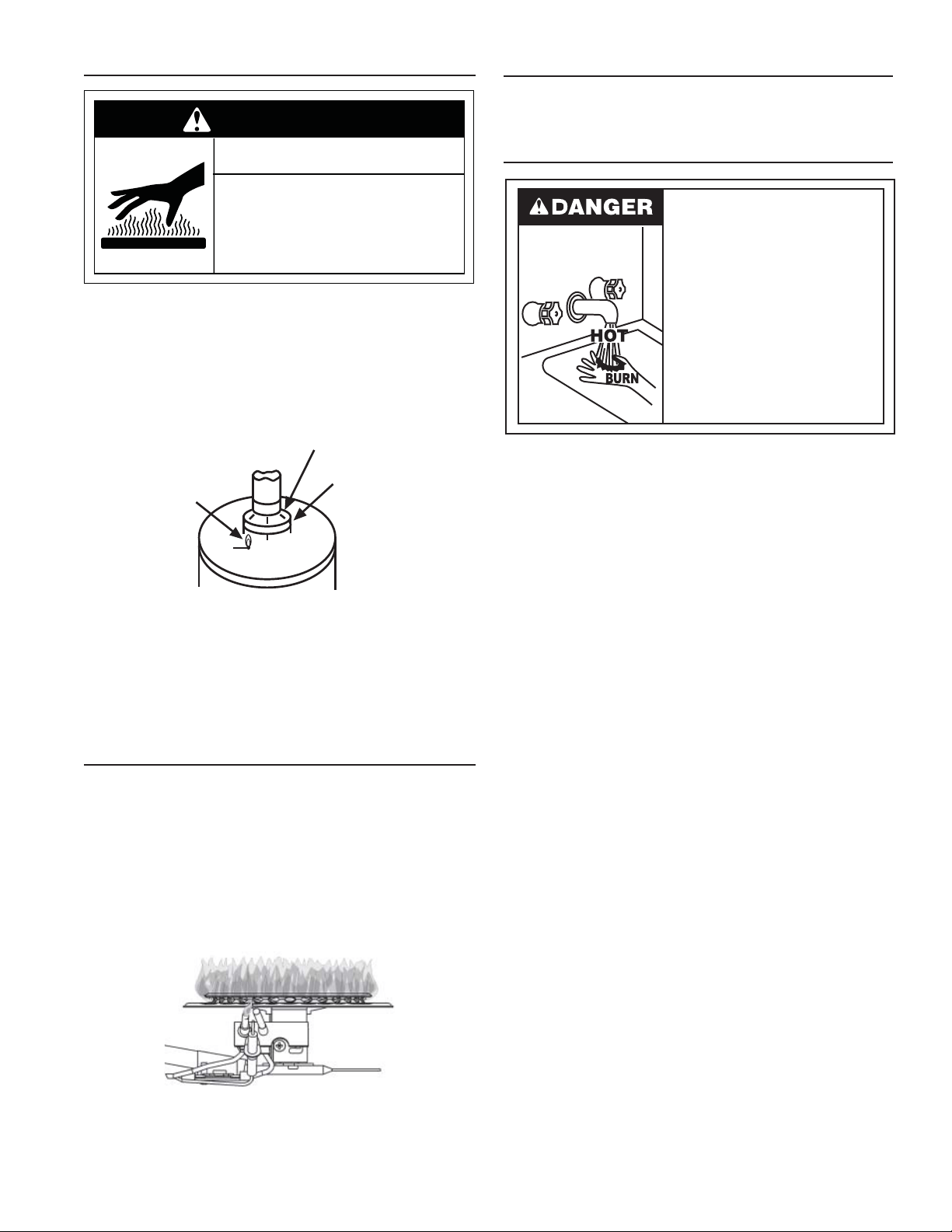
21
Checking the Draft
Do not touch vent.
Doing so can result in burns.
WARNING
Burn Hazard
After successfully lighting the water heater, allow the unit to
operate for 15 minutes and check the draft hood relief opening
for proper draft (Figure 16). Make sure all other appliances in
the area are operating and all doors are closed when performing
the draft test. Pass a match fl ame around the relief opening of
the draft hood. A steady fl ame drawn into the opening indicates
proper draft.
M
ATCH
RELIEF
OPENIN
G
DRAFT HOOD
FIGURE 16.
If the fl ame fl utters or is blown out, combustion products are
escaping from the relief opening. If this occurs, do not operate
the water heater until proper adjustments or repairs are made
to the vent pipe system and/or air supply requirements.
Burner Flames
Inspect the burner fl ames through the viewport and compare
them to the drawing in Figure 17. A properly operating burner
should produce a soft blue fl ame. Blue tips with yellow inner
cones are satisfactory. The tips of the fl ame may have a slight
yellow tint. The fl ame should not be all yellow or have a sharp
blue-orange color. Contaminated air may cause an orange
colored fl ame. Contact a qualifi ed technician if the fl ame is not
satisfactory.
FIGURE 17.
Emergency Shut Down
IMPORTANT: Should overheating occur or the gas supply fails
to shut off, turn off the water heater’s manual gas control valve
and call a qualified technician.
Water Temperature Regulation
Water temperature over 125°F (52°C)
can cause servere burns instantly
resulting in severe injury or death.
Children, the elderly, and the
physically or mentally disabled are at
highest risk for scald injury.
Feel water before bathing or
showering.
Temperature limiting valves are
available.
Read instruction manual for safe
temperature setting.
Due to the nature of the typical gas water heater, the water
temperature in certain situations may vary up to 30°F
(16.7 °C) higher or lower at the point of use such as, bathtubs,
showers, sink, etc.
HOTTER WATER CAN SCALD: Water heaters are intended to
produce hot water. Water heated to a temperature which will
satisfy space heating, clothes washing, dish washing, and other
sanitizing needs can scald and permanently injure you upon
contact. Some people are more likely to be permanently injured
by hot water than others. These include the elderly, children, the
infirm, or physically/mentally handicapped. If anyone using hot
water in your home fits into one of these groups or if there is a local
code or state law requiring a certain temperature water at the hot
water tap, then you must take special precautions. In addition to
using the lowest possible temperature setting that satisfies your
hot water needs, a means such as a mixing valve should be used
at the hot water taps used by these people or at the water heater.
Mixing valves are available at plumbing supply or hardware
stores. See Figure 12. Follow manufacturer’s instructions for
installation of the valves. Before changing the factory setting on
the gas control valve/thermostat, see Figure 18. Using the lowest
hot water temperature that meets your needs will also provide the
most energy efficient operation of the water heater.
Never allow small children to use a hot water tap, or to draw
their own bath water. Never leave a child or handicapped
person unattended in a bathtub or shower.
NOTE: A water temperature range of 120°F-140°F (49°C-60°C)
is recommended by most dishwasher manufacturers.
The gas control valve/thermostat is adjusted to the pilot position
when it is shipped from the factory. Water temperature can
be regulated by moving the temperature dial to the preferred
setting. The preferred starting point is 120°F at the “HOT”
setting. Align the knob with the desired water temperature as
shown in Figure 18. There is a hot water scald potential if the
gas control valve/thermostat is set too high.
NOTE:
• If the knob is set to a higher temperature setting than 120°F,
a mixing valve should be installed to limit the temperature of
the water to 120°F at the fixtures.
• Temperatures shown on the gas control valve/thermostat are
approximates. The actual temperature of the heated water
may vary.
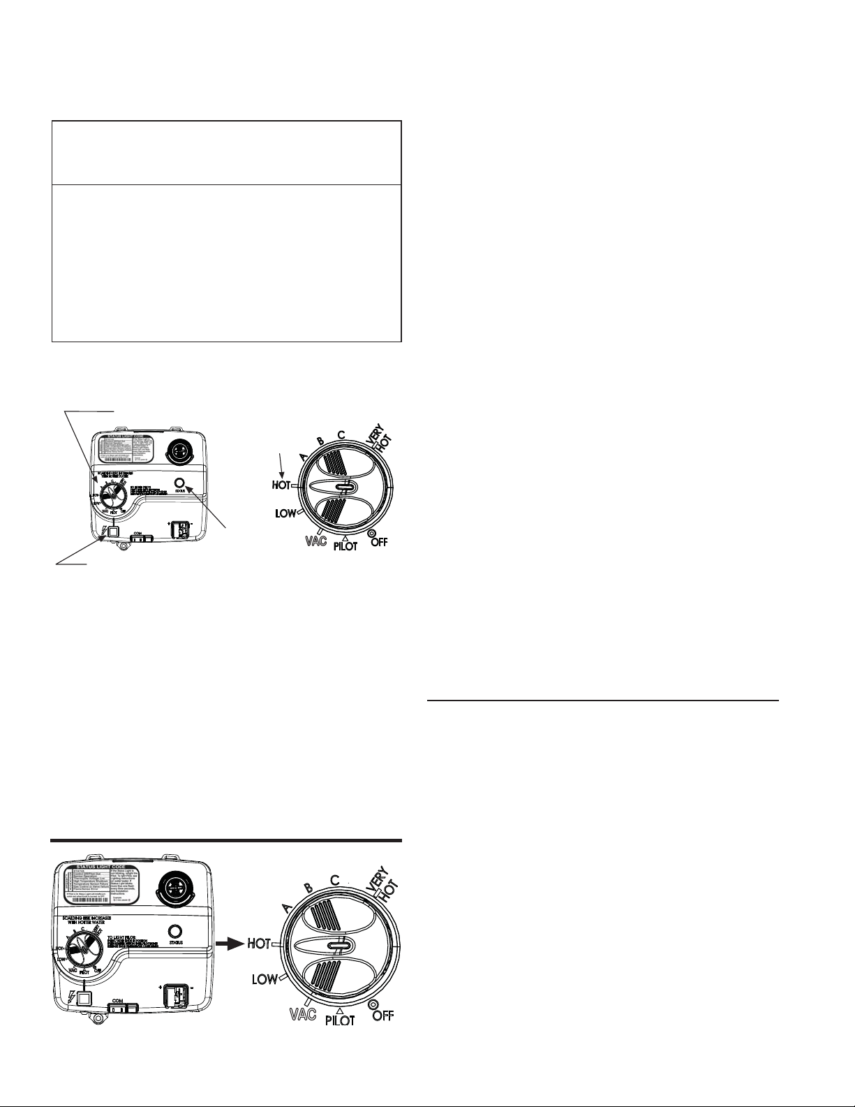
22
IMPORTANT: Adjusting the thermostat past the 120°F mark
on the temperature dial will increase the risk of scald injury. Hot
water can produce first degree burns within:
Water
Temperature °F
Time for 1st
Degree Burn
(Less Severe Burns)
Time for
Permanent Burns
2nd & 3rd Degree
(Most Severe Burns)
110
116
116
122
131
140
149
154
(normal shower temp.)
(pain threshold)
35 minutes
1 minute
5 seconds
2 seconds
1 second
Instantaneous
45 minutes
5 minutes
25 seconds
5 seconds
2 seconds
1 second
(U.S. Government Memorandum, C.P.S.C., Peter L. Armstrong, Sept. 15,1978)
VAC
GAS CONTROL VALVE/THERMOSTAT
SETTINGS
GAS CONTROL/TEMPERATURE KNOB
120°F
MARK
STATUS
LIGHT
IGNITER
FIGURE 18.
Should overheating occur or the gas supply fail to shut off, turn
off the manual gas control valve to the appliance.
NOTE: During low demand periods when hot water is not being
used, a lower thermostat setting will reduce energy losses and
may satisfy your normal hot water needs. If hot water use is
expected to be more than normal, a higher thermostat setting
may be required to meet the increased demand. When leaving
your home for extended periods (vacations, etc.) turn the
temperature dial to its lowest setting. This will maintain the water
at low temperatures with minimum energy losses and prevent
the tank from freezing during cold weather.
Operating the Temperature Control System
VAC
FIGURE 19.
Water Temperature Adjustment
The water temperature setting can be adjusted from 55°F to
155°F. Turn the Gas Control/Temperature Knob to the desired
setting/temperature.
NOTE:
The temperatures indicated are approximates. The actual
temperature of the heated water may vary.
Operating Modes and Settings
• Standard Mode - The controller adjusts the water heater to
maintain the temperature set by the user.
• Vacation Setting - The Vacation setting (VAC) sets
the controller at approximately 55°F. This setting is
recommended when the water heater is not in use for a
long period of time. This effectively turns the controller
temperature setting down to a temperature that prevents
the water in the water heater from freezing while still
conserving energy.
Status Light Code
Normal Flashes:
• 0 Flashes Indicates Control Off/Pilot Out.
• 1 Flash Indicates Normal Operation.
• A solid status light indicates that the gas control
valve/thermostat is shutting down.
Diagnostic Flashes:
If the water heater is not working, look for the following diagnostic
flashes after lighting the pilot. For more details, see “
Status Light
and Diagnostic Code Troubleshooting Chart
.”
2 Flashes Indicates Thermopile Voltage Low
4 Flashes Indicates Overheat Failure
5 Flashes Indicates Sensor Failure
7 Flashes Indicates Electronic Control Failure
8 Flashes See “Status Light and Diagnostic Code
Troubleshooting Chart.”
Operational Conditions
Condensation
Whenever the water heater is filled with cold water, some
condensate will form while the burner is on. A water heater may
appear to be leaking when in fact the water is condensation. This
usually happens when:
a. A new water heater is filled with cold water for the first time.
b. Burning gas produces water vapor in water heaters,
particularly high efficiency models where flue temperatures
are lower.
c. Large amounts of hot water are used in a short time and the
refill water in the tank is very cold.
Moisture from the products of combustion condense on the
cooler tank surfaces and form drops of water which may fall
onto the burner or other hot surfaces to produce a “sizzling” or
“frying” noise.
Excessive condensation can cause pilot outage due to water
running down the flue tube onto the main burner and putting out
the pilot.
Because of the suddenness and amount of water, condensation
water may be diagnosed as a “tank leak”. After the water in the
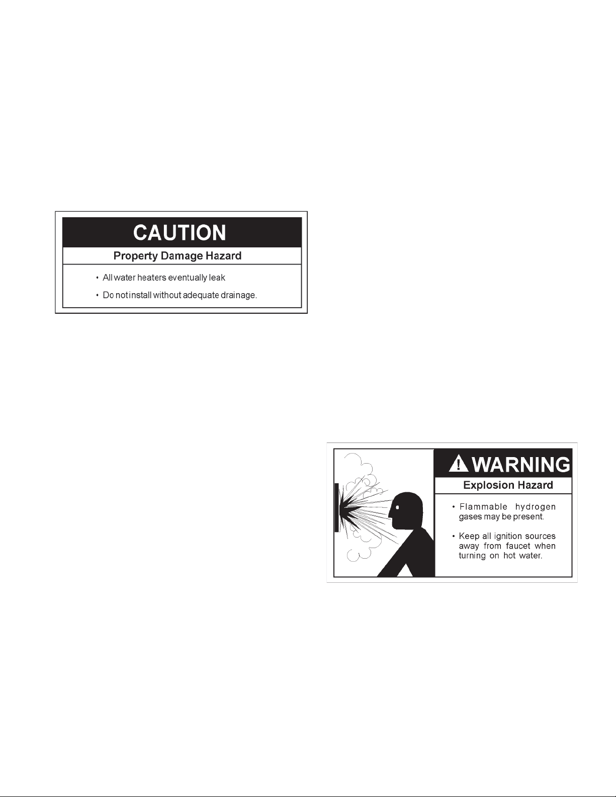
23
tank warms up (about 1-2 hours), the condition should disappear.
Do not assume the water heater is leaking until there has been
enough time for the water in the tank to warm up.
An undersized water heater will cause more condensation.
The water heater must be sized properly to meet the family’s
demands for hot water including dishwashers, washing
machines and shower heads.
Excessive condensation may be noticed during the winter and
early spring months when incoming water temperatures are at
their lowest.
Good venting is essential for a gas fired water heater to operate
properly as well as to carry away products of combustion and
water vapor.
It is always recommended that a suitable metal drain pan be
installed under the water heater to protect the area from water
damage resulting from normal condensation production, a leaking
tank or piping connections. Refer to the “Site Location” section.
Water Heater Sounds
During the normal operation of the water heater, sounds or noises
may be heard. These noises are common and may result from
the following:
1. Normal expansion and contraction of metal parts during
periods of heat-up and cool-down.
2. Condensation causes sizzling and popping within the
burner area and should be considered normal.
3. Sediment buildup in the tank bottom will create varying
amounts of noise and may cause premature tank failure.
Drain and flush the tank as directed under the “Draining
and Flushing” section.
Smoke/Odor
The water heater may give off a small amount of smoke and odor
during the initial start-up of the unit. This is due to the burning
off of oil from metal parts of a new unit and will disappear after a
brief period of operation.
Safety Shut-off and Thermal Switch
This water heater is designed to automatically shut-off in the
event of the following:
1. The pilot flame is extinguished for any reason.
2. The water temperature exceeds 189°F (87°C).
3. Excessive combustion chamber temperatures.
4. The ignition of flammable vapors.
A thermopile is used to determine if a pilot flame is present, and
will shut off the gas supply to the main burner and the pilot if the
flame is absent. This unit is also equipped with a thermal switch,
designed to shut off the gas supply in the event the heater has
been exposed to flammable vapors (spilled gasoline or paint
fumes, for example), poor combustion caused by insufficient
combustion air, or improper venting. If the switch opens, check
the flame arrestor for signs of high temperature (blue or black
discoloration), and inspect your installation for any problems
with venting or combustion air. (See Pilot Light Troubleshooting
Flowchart). Reset the switch by depressing the small button in
the center of the switch.
IMPORTANT: Correct any issues prior to resetting the switch.
Contact a qualified technician to request service.
The gas control valve\thermostat includes a temperature limiting
ECO (Energy Cut Off) system that will shut off the water heater
if the water temperature exceeds 189°F (87°C).
Should the water temperature get too high, the diagnostic
status light will flash a code (4 flashes), indicating an over-
temperature condition and the main burner will be shut off. If
a high temperature condition occurs, turn the main gas supply
OFF and have the water heater repaired by a qualified service
technician.
“Air” in Hot Water Faucets
HYDROGEN GAS: Hydrogen gas can be produced in a hot
water system that has not been used for a long period of time
(generally two weeks or more). Hydrogen gas is extremely
flammable and explosive. To prevent the possibility of injury
under these conditions, we recommend the hot water faucet,
located farthest away, be opened for several minutes before
any electrical appliances which are connected to the hot water
system are used (such as a dishwasher or washing machine).
If hydrogen gas is present, there will probably be an unusual
sound similar to air escaping through the pipe as the hot water
faucet is opened. There must be no smoking or open flame
near the faucet at the time it is open.
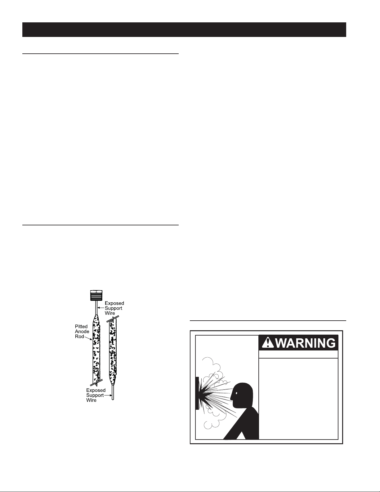
24
MAINTENANCE OF YOUR WATER HEATER
Routine Preventive Maintenance
At least annually, a visual inspection should be made of the
venting and air supply system, piping systems, main burner,
pilot burner, and fl ame-arrestor. Check the water heater for the
following:
• Obstructions, damage, or deterioration in the venting
system. Make sure the ventilation and combustion air
supplies are not obstructed.
• Clean any dust or debris from the base-ring filter.
• Soot and/or carbon on the main burner and pilot burner.
Contact a qualified technician.
• Leaking or damaged water and gas piping.
• Presence of flammable or corrosive materials in the
installation area.
• Presence of combustible materials near the water heater.
• After servicing this water heater, check to make sure it
is working properly. (See “Operating Your Water Heater”
section of this manual.)
IMPORTANT: If you lack the necessary skills required to
properly perform this visual inspection, you should not proceed,
but get help from a qualifi ed technician.
Anode Rod Inspection
Each water heater contains at least one anode rod, which will
slowly deplete (due to electrolysis) prolonging the life of the
water heater by protecting the glass-lined tank from corrosion.
Adverse water quality, hotter water temperatures, high hot
water usage, and water softening methods can increase the
rate of anode rod depletion. Once the anode rod is depleted,
the tank will start to corrode, eventually developing a leak.
Anode Rod Depletion
FIGURE 20.
Certain water conditions will cause a reaction between the
anode rod and the water. The most common complaint
associated with the anode rod is a “rotten egg smell” produced
from the presence of hydrogen sulfi de gas dissolved in the
water. IMPORTANT: Do not remove this rod permanently as it
will void any warranties. A special anode rod may be available
if water odor or discoloration occurs. NOTE: This rod may
reduce but not eliminate water odor problems. The water
supply system may require special fi ltration equipment from a
water conditioning company to successfully eliminate all water
odor problems.
Artifi cially softened water is exceedingly corrosive because the
process substitutes sodium ions for magnesium and calcium
ions. The use of a water softener may decrease the life of the
water heater tank.
The anode rod should be inspected after a maximum of three
years and annually thereafter until the condition of the anode
rod dictates its replacement. NOTE: Artifi cially softened water
requires the anode rod to be inspected annually. The following
are typical (but not all) signs of a depleted anode rod:
• The majority of the rods diameter is less than 3/8”.
• Signifi cant sections of the support wire (approx. 1/3 or more
of the anode rod’s length) are visible.
If the anode rod show signs of either or both it should be
replaced. NOTE: Whether re-installing or replacing the anode
rod, check for any leaks and immediately correct if found. In
replacing the anode:
1. Turn off gas supply to the water heater.
2. Shut off the water supply and open a nearby hot water
faucet to depressurize the water tank.
3. Drain approximately 5 gallons of water from tank. (Refer to
“Draining and Flushing” for proper procedures). Close drain
valve.
4. Remove old anode rod.
5. Use Tefl on® tape or approved pipe sealant on threads and
install new anode rod.
6. Turn on water supply and open a nearby hot water faucet
to purge air from water system. Check for any leaks and
immediately correct any if found.
7. Restart the water heater as directed in this manual. See the
Repair Parts Illustration for anode rod location.
Temperature-Pressure Relief Valve Operation
Explosion Harzard
• Temperature-pressure relief
valve must comply with ANSI
Z21.22-CSA 4.4 and ASME
code.
• Properly sized temperature-
pressure relief valve must be
installed in opening provided.
• Can result in overheating
and excessive tank pressure.
• Can cause serious injury or
death.
Manually operate the temperature and pressure relief valve
at least once a year to make sure it is working properly. To
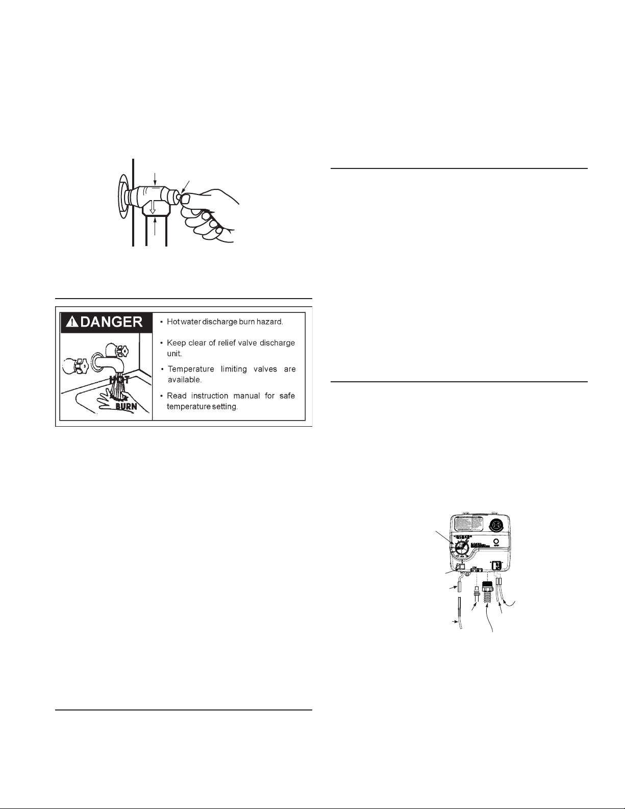
25
prevent water damage, the valve must be properly connected
to a discharge line which terminates at an adequate drain (see
Figure 1). Standing clear of the outlet (discharged water may be
hot), slowly lift and release the lever handle on the temperature
and pressure relief valve to allow the valve to operate freely and
return to its closed position. See Figure 21. If the valve fails to
completely reset and continues to release water, immediately
close the manual gas shut-off valve and the cold water inlet valve
and call a qualifi ed technician. Do not plug the temperature-
pressure relief valve or discharge line.
TEMPERATURE AND PRESSURE
RELIEF VALVE
DISCHARGE LINE TO DRAIN
MANUAL RELIEF
VALVE
FIGURE 21.
Draining and Flushing
It is recommended that the tank be drained and fl ushed
every 6 months to remove sediment which may build up during
operation. The water heater should be drained if being shut
down during freezing temperatures. To drain the tank, perform
the following steps:
1. Turn off the gas to the water heater at the manual gas
shut-off valve.
2. Open a nearby hot water faucet until the water is no longer hot.
3. Close the cold water inlet valve.
4. Connect a hose to the drain valve and terminate it to an
adequate drain or external to the building.
5. Open the water heater drain valve and allow all of the
water to drain from the tank. Flush the tank with water as
needed to remove sediment.
6. Close the drain valve, refi ll the tank, and restart the heater
as directed in this manual. If the water heater is going
to be shut down for an extended period, the drain valve
should be left open.
IMPORTANT: Condensation may occur when refi lling the tank
and should not be confused with a tank leak.
Replacement Parts
IMPORTANT: The following maintenance procedures are for
the FVIR System components and should be performed by a
qualifi ed technician.
Replacement parts may be ordered through your plumber or
the local distributor. Parts will be shipped at prevailing prices
and billed accordingly. When ordering replacement parts,
always have the following information ready:
1. model, serial, and product number
2. type of gas
3. item number
4. parts description
See Repair Parts Illustration for a list of available repair parts.
External Inspection & Cleaning of the
Base-Ring Filter
1. At least annually, check the base-ring filter (Figure 28) for
any dust or debris that may have accumulated on the filter
screen. NOTE: If the water heater is located in an area
that is subjected to lint and dirt, it may be necessary to
check the base-ring filter more frequently.
2. Follow the Lighting Instructions to turn off the water heater
and allow it to cool for 10 minutes before attempting to clean
the base-ring filter.
3. Use a vacuum cleaner with a hose attachment to remove
any dust or debris that may have accumulated on the
filter. NOTE: If unable to inspect or clean the base-ring filter,
follow the “Cleaning the Combustion Chamber and Flame-
arrestor” instructions.
4. After the base-ring filter has been cleaned, follow the
Lighting Instructions to return the water heater to service.
Removing the Manifold/Burner Assembly
1. Turn the gas control/temperature knob to the “OFF”
position (Figure 18).
2. Before per
forming any maintenance, it is important to turn off
the gas supply to the water heater at the manual gas shut-off
valve. This valve is typically located beside the water heater.
Note the position of the shut-off valve in the open/on position,
then proceed to turn it off (Figure 7).
3. With the unit shut-off, allow sufficient time for the water heater
to cool before performing any maintenance.
IGNITER
WIRE
RED WIRE
(LEFT SIDE)
PILOT
TUBE
MANIFOLD TUBE
IGNITER
BUTTON
IGNITER
LEAD
WIRE
WHITE
WIRE
(RIGHT
SIDE)
GAS CONTROL/
TEMPERATURE KNOB
VAC
FIGURE 22.
4. Remove the outer door.
5. Disconnect the following from the gas control valve/thermostat:
pilot tube (7/16” wrench), igniter wire (from the igniter lead
wire), and manifold tube (3/4” wrench). See Figure 22.
6. Disconnect the white and red wires from the gas control valve/
thermostat (Figure 22). Use needle nose pliers to grip the
connector(s). IMPORTANT: Grip the connector carefully to
prevent damage. Do not grip or pull the wires themselves.
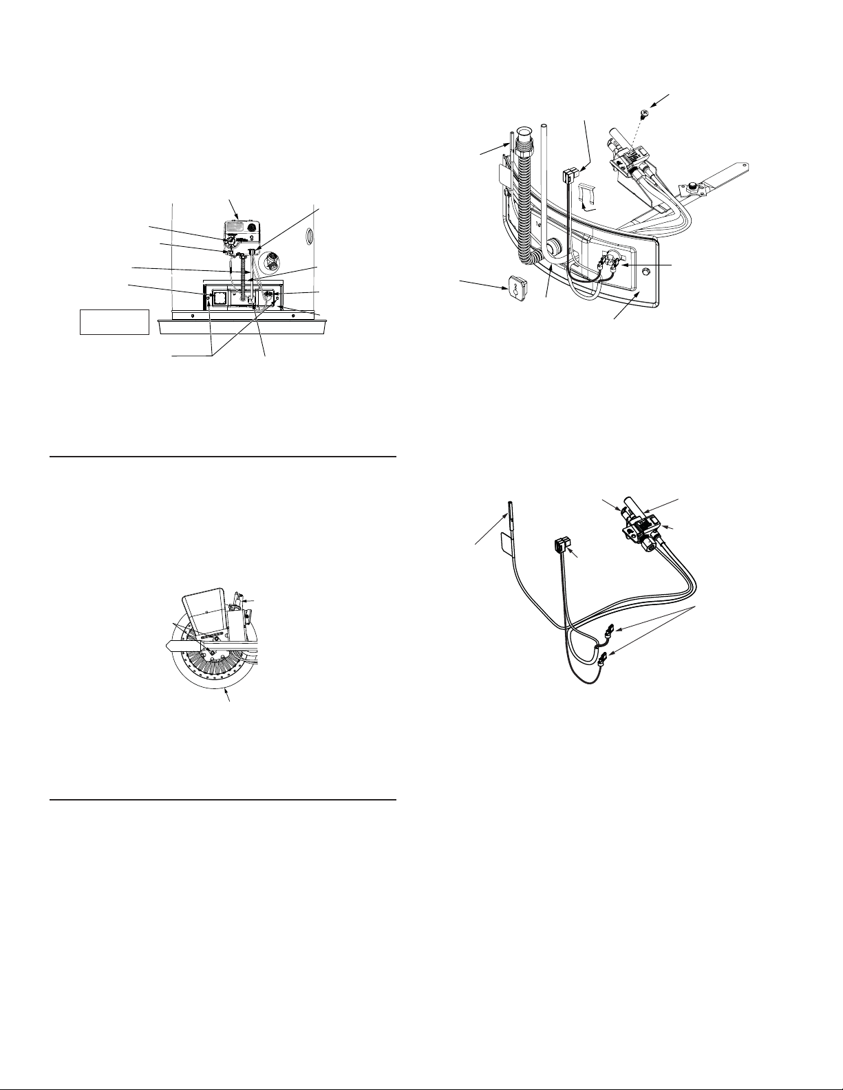
26
7. Grasp the manifold tube and push down slightly to free the
manifold tube and pilot tube.
8. Remove the screws (1/4” nut driver) securing the
manifold/burner assembly to the combustion chamber.
See Figure 23
.
9. Carefully remove the manifold/burner assembly from the
combustion chamber. BE SURE NOT TO DAMAGE ANY
INTERNAL PARTS.
VAC
MANIFOLD SCREW (2)
MANIFOLD COMPONENT BLOCK
MANIFOLD DOOR
THERMAL SWITCH
PILOT TUBE
MANIFOLD TUBE
VIEWPORT
THERMOPILE AND
SWITCH WIRE
CONNECTIONS
PIEZO IGNITER BUTTON
GAS CONTROL VALVE/THERMOSTAT
GAS CONTROL/
TEMPERATURE KNOB
OUTER DOOR
NOT SHOWN
FIGURE 23.
Removing the Burner from the Manifold/
Burner Assembly
Natural Gas (Low Nox) & L.P. Gas Burner
1. Take off the burner by removing the two (2) screws located
underneath the burner.
2. Check the burner to see if it is dirty or clogged. The burner
may be cleaned with soap and hot water (Figure 24).
BURNER
(BOTTOM VIEW)
SCREWS
PILOT ASSEMBLY
(BOTTOM VIEW)
FIGURE 24.
Replacing the Pilot/ Thermopile Assembly
1. Remove the manifold door assembly as described in
“Removing the Manifold/Burner Assembly” section.
2. Remove the burner to access the pilot/thermopile assembly.
Remove and keep the screws securing the burner to the
manifold (Figure 24). IMPORTANT: DO NOT remove the orifice.
3. Remove the screw securing the pilot/thermopile assembly to
the pilot bracket and keep for reuse later (Figure 25).
4. Lift the retainer clip straight up from the back of the manifold
component block (using a fl at-blade screwdriver), then
remove the manifold component block from the manifold door
(Figure 25). IMPORTANT: Be careful not to bend or alter the
position of the pilot tube. It will be used as a bending template
for the new pilot assembly. Note the placement/order of the
wires in the manifold component block.
5. Lift the pilot/thermopile assembly (including the igniter wire) from
the manifold assembly.
CONNECTORS
MANIFOLD COMPONENT
BLOCK
PILOT TUBE
IGNITER
WIRE
BURNER AND OTHER
FITTINGS NOT SHOW
FOR CLARITY.
MANIFOLD DOOR
RED WIRES TO
THERMAL SWITCH (2)
RETAINER
CLIP
PILOT / THERMOPILE
ASSEMBLY SCREW
FIGURE 25.
6. Read this step carefully before proceeding. Using the old
pilot/pilot tube assembly as a guide, bend the new pilot tube
to match the old one. Make only the bends closest to the pilot
before going to the next step.
PILOT/THERMOPILE ASSEMBLY
PILOT/THERMOPILE
ASSEMBLY
IGNITER
CONNECTOR
THERMAL
SWITCH
CONNECTORS
(RED WIRES)
PILOT
THERMOPILE
CONNECTORS
(CONNECT AT
GAS CONTROL VALVE/
THERMOSTAT)
FOR CLARITY, PILOT
TUBE NOT SHOWN .
FIGURE 26.
7. Route the new pilot tube and wires through the opening in the
manifold door. See Figure 25.
8. Using the pilot screw removed earlier, attach the new pilot/
thermopile assembly. Reattach the burner to the manifold using
the screws removed earlier. NOTE: Make sure the burner scoop
is oriented to the pilot side of the manifold tube (Figure 24).
9. Reinstall the manifold component block in the manifold door.
Ensure that the pilot tube and wires are positioned as shown
in Figure 27.
10. Carefully bend the new pilot tube to match the bend of the
manifold tube. NOTE: When bending, DO NOT crimp or crease
the pilot tube.
11. Before you proceed to the next step, install the new brass ferrule
nut in the gas control valve/thermostat’s pilot tube opening,
HAND TIGHT ONLY.
12. Install the manifold/burner assembly. Refer to the “Replacing
the Manifold/Burner Assembly” section for instructions.
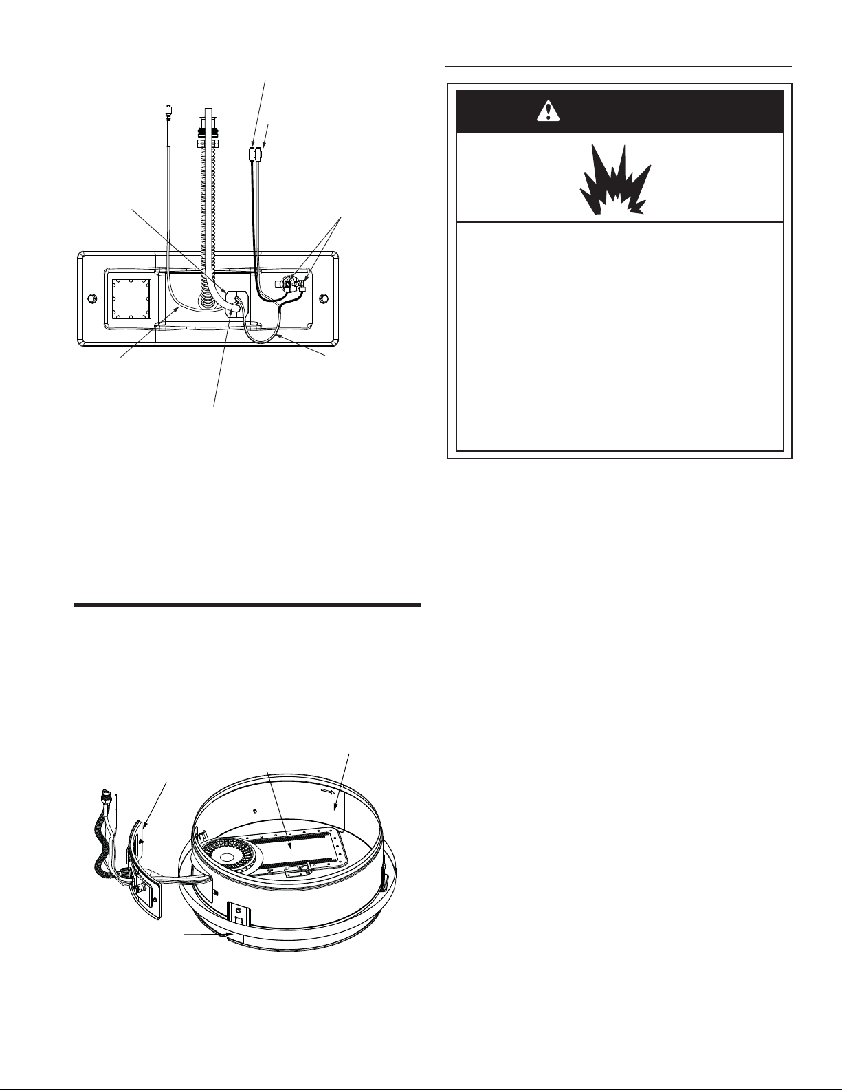
27
RED THERMAL SWITCH WIRE
CONNECTIONS AT MANIFOLD DOOR
RED (+) THERMAL SWITCH WIRE
CONNECTS TO THE GAS CONTROL
VALVE\THERMOSTAT.
WHITE (-) THERMOPILE WIRE
CONNECTS TO THE GAS CONTROL
VALVE\THERMOSTAT.
IGNITER WIRE PASSES
THROUGH CENTER OF
MANIFOLD COMPONENT
BLOCK (SMALLEST HOLE)
PILOT TUBE PASSES
THROUGH BOTTOM HOLE
OF MANIFOLD COMPONENT
BLOCK (LARGEST HOLE)
THERMOPILE WIRES PASS
THROUGH TOP HOLE OF
MANIFOLD COMPONENT
BLOCK
MANIFOLD
COMPONENT
BLOCK
FIGURE 27.
Cleaning the Combustion Chamber and
Flame-arrestor
1. Follow procedure outlined in “Removing the Manifold/
Burner Assembly”.
2. Use a vacuum cleaner/shop vac to remove all loose debris
in the combustion chamber (Figure 28). Use compressed
air to clear any dust or debris that may have accumulated
in the flame-arrestor.
DOOR GASKET
FLAME ARRESTOR
COMBUSTION CHAMBER
BASE-RING
FILTER
FIGURE 28.
3. Reassemble following the procedure under “Replacing the
Manifold/Burner Assembly.”
Replacing the Manifold/Burner Assembly
WARNING
Explosion Hazard
Tighten both manifold door screws securely.
Remove any fiberglass between gasket and
combustion chamber.
Replace viewport if glass is missing or damaged.
removed.
Replace door gasket if damaged.
Failure to follow these instructions can result in
death, explosion, or fire.
Replace manifold component block if missing or
1. Check the door gasket for damage or imbedded debris
prior to installation (Figure 28).
2. Inspect the viewport for damage and replace as required
(Figure 23).
3. Insert the new manifold/burner assembly into the burner
compartment, making sure that the tab of the manifold
tube engages the slot of the bracket inside the combustion
chamber (Figure 29).
4. Inspect the door gasket and make sure there is no
fiberglass insulation between the gasket and the
combustion chamber (Figure 28).
5. Tighten the two screws that secure the manifold/burner
assembly to the combustion chamber. (Use a 1/4” nut
driver.) There should be no space between the gasket part
of the manifold door and combustion chamber.
IMPORTANT: Do not operate the water heater if the door
gasket does not create a seal between the manifold door
and the combustion chamber.
6. Reconnect the manifold tube (3/4” wrench) and pilot tube
(7/16” wrench) to the gas control valve/thermostat (Figure 22).
Do not cross-thread or apply any thread sealant to the fittings.
IMPORTANT: If you were supplied with a new ferrule
nut in a parts kit, follow these steps to connect the
pilot tube:
1.) Install the ferrule nut into the gas valve at the pilot tube
location, hand tight only. 2.) Insert the pilot tube into the
ferrule nut until the tube bottoms out, then tighten the nut
with a 7/16” wrench until the crimp connection seals to the
pilot tube. 3.) Continue to tighten until the nut is tight in the
gas valve.
7. Connect the white and red wires to the gas control valve/
thermostat as shown in Figure 22. Also, ensure that the
red thermal switch wires are connected to the thermal
switch on the manifold door (Figure 27).
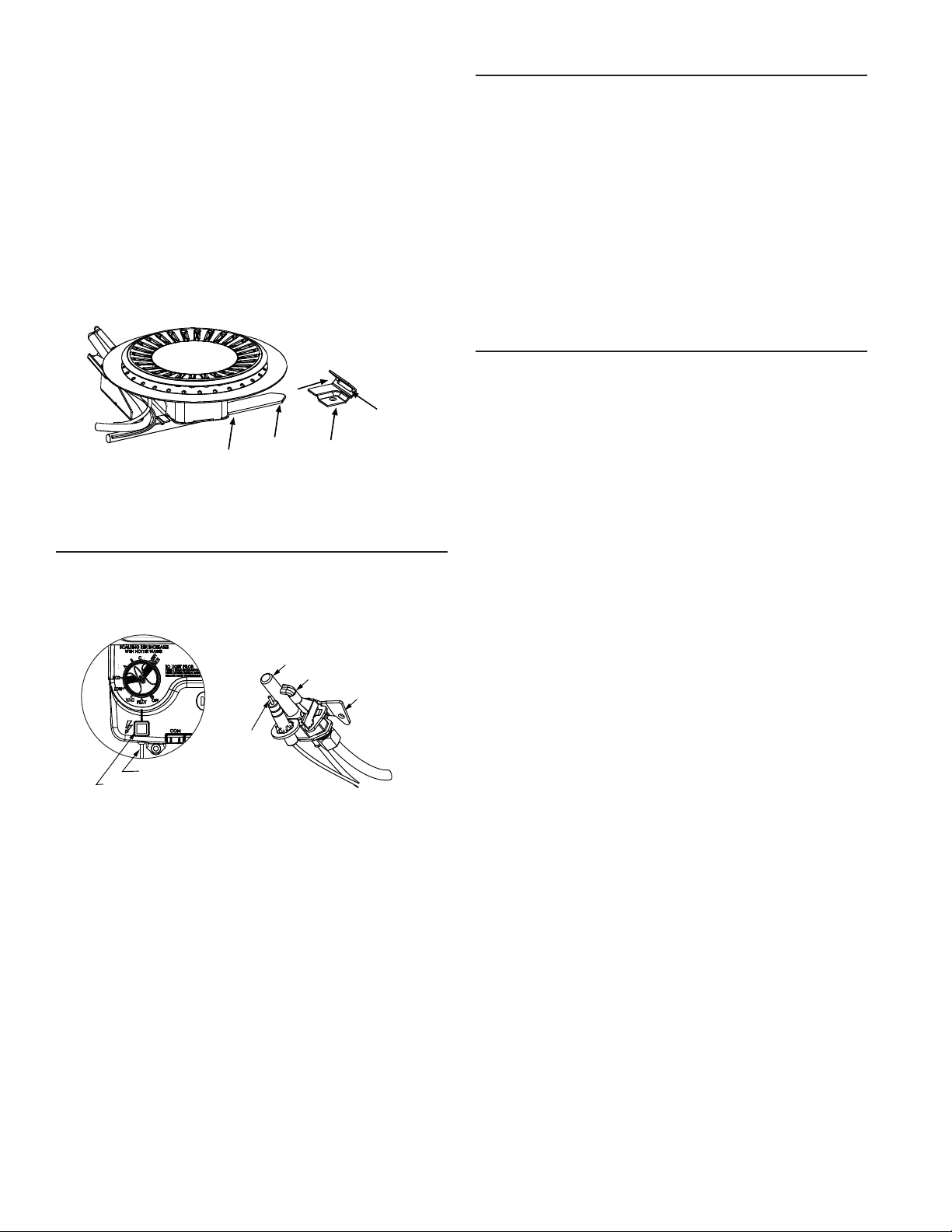
28
8. Reconnect the igniter wire (Figure 22).
9. Turn on the gas supply to the water heater at the manual gas
shut-off valve (Figure 7).
10. Follow the lighting instructions on the front of the water
heater. With the main burner lit, check for leaks at the
manifold and pilot connections by brushing on an approved
noncorrosive leak detection solution. If such a solution is
not available, use a mixture of hand dish washing soap and
water (one part soap to 15 parts water) or children’s soap
bubble solution. Bubbles forming indicate a leak. Correct
any leak found.
11. Verify proper operation, then replace the outer door.
MANIFOLD TUBE
TIP
BRACKET
SLOT
CLOSE-UP INSIDE VIEW OF
THE COMBUSTION CHAMBER.
FIGURE 29.
Piezoelectric Igniter System
The piezoelectric igniter system consists of the igniter button,
electrode, and wire. The pilot is ignited by an electric spark
generated when the igniter button is pressed. (See Figure 30).
VAC
PILOT/
THERMOPILE
BRACKET
ELECTRODE
THERMOPILE
PILOT
IGNITER BUTTON
WIRE TO ELECTRODE
FIGURE 30.
Testing the Igniter System
Turn off the gas to the water heater at the manual gas shut-off
valve. Watch the electrode tip while activating the igniter. A
visible spark should jump from the electrode. To avoid shock,
do not touch the burner or any metal part on the pilot or pilot
assembly. If no spark is visible, check the wire connections
and make sure the electrode is not broken. Replace the igniter
if defective. Dirt and rust on the pilot or electrode tip can
prevent the igniter spark. Wipe clean with a damp cloth and dry
completely. Rust can be removed from the electrode tip and
metal surfaces by lightly sanding with an emery cloth or fi ne
grit sandpaper.
Removing and Replacing the Gas Control
Valve/Thermostat
IMPORTANT: This water heater has a resettable thermal switch
installed. Do not attempt to disable or modify this feature in any
way. Use only factory authorized replacement parts. IMPORTANT:
This gas control valve/thermostat is shipped from the factory as
a natural gas unit. However, it may be converted to use LP gas.
Before installing this gas control valve/ thermostat, make sure
that it is confi gured for the type of gas that you are using. Refer
to the “Gas Conversion” section.
Removing the Gas Control Valve/Thermostat:
1. Turn the gas control/temperature knob to the “OFF” position
(Figure 18).
2. Turn off the gas at the manual shut-off valve on the gas
supply pipe (Figure 7).
3. Drain the water heater. Refer to the section of “Draining and
Flushing” and follow the procedure.
4. Disconnect the igniter wire from the igniter lead wire. Use
needle nose pliers to disconnect the red (+) and white (-)
thermopile wires. Disconnect the pilot tube (7/16” wrench) and
manifold tube (3/4” wrench) at the gas control valve/thermostat
(Figure 22).
5. Refer to “Gas Piping” (Figure 7) and disconnect the ground
joint union in the gas piping. Disconnect the remaining pipe
from the gas control valve/thermostat.

29
6. To remove the gas control valve/thermostat, thread
a 4” section of gas pipe into the inlet and use it to turn the
gas control valve/thermostat (counterclockwise.) Do not
use a pipe wrench or equivalent to grip body. Damage may
result, causing leaks. Do not insert any sharp objects into
the inlet or outlet connections. Damage to the gas control
valve/thermostat may result.
Replacing the Gas Control Valve/Thermostat:
To replace the gas control valve/thermostat, reassemble in reverse
order. When replacing the gas control valve/thermostat, thread
a 4” section of gas pipe into the inlet and use it to turn the gas
control valve/thermostat (clockwise). DO NOT OVER TIGHTEN;
damage may result.
• Be sure to use approved Teflon® tape or pipe joint
compound on the gas piping connections and fitting on the
back of the gas control valve that screws into the tank.
• Be sure to remove the pilot ferrule nut from the new gas
control valve/thermostat.
• Turn the main gas supply on and check the gas supply
connections for leaks. Correct any leak found. Next, light
the pilot and main burner, then check the manifold tube and
pilot tube connections for leaks. Correct any leak found.
Use an approved noncorrosive leak detection solution.
If such a solution is not available, use a mixture of hand
dish washing soap and water (one part soap to 15 parts
water) or children’s soap bubble solution. Bubbles forming
indicate a leak.
• Be sure tank is completely filled with water before lighting
and activating the water heater. Follow the “Lighting
Instructions” on the front of the water heater.
• If additional information is required, contact Residential
Technical Assistance.
TEFLON
®
is a registered trademark of E.I. Du Pont De Nemours
and Company.
FVIR System Operational Checklist
1. Manifold gasket properly sealed.
2. Viewport not damaged or cracked.
3. Flame-arrestor free of debris and undamaged.
4. Manifold component block properly installed.
5. No leaks at pilot and manifold connection.
6. Manifold door screws securely tightened.
7. Depress the button on the thermal switch.

30
TROUBLESHOOTING CHART
NOITCA EVITCERROC)S(ESUAC ELBISSOPMELBORP
BURNER WILL NOT IGNITE 1. Pilot not lit
2. Thermostat set too low
3. Main burner line clogged
4. Non-functioning thermostat
5. Base-Ring Filter blocked with lint/dust
6. Heater installed in a confined area
7. FVIR Flame Arrestor blocked with lint/
dust.
1. Light pilot
2. Turn temp. dial to desired temperature
3. Clean, locate source and correct
4. Test Gas Control Valve/Thermostat
5. Clean filter, See “External Inspection &
Cleaning of the Base-Ring Filter
” section.
6. Provide fresh air ventilation
7. Clean filter, See “Cleaning the Combustion
Chamber and Flame-Arrestor” section.
SMELLY WATER 1. Sulfides in the water 1. Replace the anode with a special anode
BURNER FLAME YELLOW-
LAZY
1. Insufficient combustion air
2. Low gas pressure
3. Water heater flue or vent system
blocked
4. Main burner line clogged
5. Base-Ring Filter blocked with lint/ dust
6. Heater installed in a confined area
7. FVIR Flame Arrestor blocked with lint/
dust.
8. Obstruction in main burner orifice
9. Incorrect gas conversion (if unit was
converted to use a different type of gas)
1. Provide ventilation to water heater
2. Check with gas utility company
3. Clean, locate source and correct
4. Clean, locate source and correct
5. Clean filter, See “External Inspection &
Cleaning of the Base-Ring Filter” section.
6. Proper fresh air ventilation
7. Clean filter, See “Cleaning the Combustion
Chamber and Flame-Arrestor” section.
8. Clean or replace orifice
9. Contact a qualified technician
PILOT WILL NOT LIGHT OR
REMAIN LIT
1. Non-functioning igniter
2. The thermal switch tripped
3. Wire lead connection at thermal switch
loose
4. Thermopile connection loose
5. Air in gas line
6. Low gas pressure
7. No gas
8. Dirt in gas lines
9. Cold drafts
10. Thermostat temperature limit was
exceeded. Status light will blink 4 flashes.
11. Pilot line or orifice clogged
12. Non-functioning thermopile
13. Air for combustion obstructed
14. F
VIR Flame Arrestor blocked with lint/
dust
15. Flammable vapors incident, FVIR
function actuated
16. Base-Ring Filter blocked with lint/dust
1. Replace igniter pilot assembly
2. See Pilot Light Troubleshooting Flowchart section
3. Remove and reconnect the wire leads at
thermal switch, confirm connections are tight
and not loose
4. Seat connector firmly in socket
5. Bleed the air from the gas line
6. Check with gas utility company
7. Check with gas utility company
8. Notify utility-install dirt trap in gas line
9. Locate source and correct
10. Replace thermostat
11. Clean, locate source and correct
12. Replace thermopile
13. See maintenance section for inspection and
cleaning of flame arrester
14. Clean filter, See “Cleaning the Combustion
Chamber and Flame-Arrestor” section.
15. Replace water heater, eliminate flammable
vapors source. Contact Technical Assistance.
16. Clean filter, See “External Inspection &
Cleaning of the Base-Ring Filter” section.
HIGH OPERATION COSTS 1. Thermostat set too high
2. Sediment or lime in tank
3. Water heater too small for job
4. Wrong piping connections
5. Leaking faucets
6. Gas leaks
7. Wasted hot water
8. Long runs of exposed piping
9. Hot water piping in exposed wall
1. Set temperature dial to lower setting
2. Drain/flush-provide water treatment if needed
3. Install adequate heater
4. Correct piping-inlet tube must be in cold inlet
5. Repair faucets
6. Check with utility-repair at once
7. Advise customer
8. Insulate piping
9. Insulate piping
INSUFFICIENT HOT WATER 1. Thermostat set too low
2. Sediment or lime in tank
3. Water heater too small
4. Wrong piping connections
5. Leaking faucets
6. Wasted hot water
7. Long runs of exposed piping
8. Hot water piping in outside wall
9. Low gas pressure
10. Incorrect gas conversion (if unit was
converted to use a different type of gas)
1. Turn temperature dial to desired setting
2. Drain/flush-provide water treatment if needed
3. Install adequate heater
4. Correct piping-inlet tube must be in cold inlet
5 Repair faucets
6. Advise customer
7. Insulate piping
8. Insulate piping
9. Check with gas utility company
10. Contact a qualified technician
31
TROUBLESHOOTING CHART (CONTINUED)
NOITCA EVITCERROC)S(ESUAC ELBISSOPMELBORP
SLOW HOT WATER
RECOVERY
1. Insufficient combustion air
2. Water heater flue or vent system
blocked
3. Low gas pressure
4. Improper calibration
5. Base-Ring Filter blocked with lint/dust
6. FVIR Flame Arrestor blocked with lint/
dust.
7. Incorrect gas conversion (if unit was
converted to use a different type of gas)
1. Provide ventilation to water heater. Check flue
way, flue baffle, and burner
2. Clean flue, locate source and correct
3. Check with gas utility company
4. Replace thermostat
5. Clean filter, See “External Inspection &
Cleaning of the Base-Ring Filter” section.
6. Clean filter, See “Cleaning the Combustion
Chamber and Flame-Arrestor” section.
7. Contact a qualified technician
DRIP FROM RELIEF VALVE 1. Excessive water pressure
2. Heater stacking
3. Closed water system
1. Use a pressure reducing valve and relief valve
2. Lower the thermostat setting
3. See “Closed System/Thermal Expansion”
THERMOSTAT FAILS TO
SHUT-OFF
1. Thermostat not functioning properly
2. Improper calibration
1. Replace thermostat
2. Replace thermostat
COMBUSTION ODORS 1. Insufficient combustion air
2. Water heater flue or vent system
blocked
3. Heater installed in a confined area
4. Base-Ring Filter blocked with lint/dust
5. FVIR Flame Arrestor blocked with lint/
dust.
1. Provide ventilation to water heater. Check flue
way, flue baffle, and burner
2. Clean, locate source and correct
3. Provide fresh air ventilation
4. Clean filter, See “External Inspection &
Cleaning of the Base-Ring Filter” section.
5. Clean filter, See “Cleaning the Combustion
Chamber and Flame-Arrestor” section.
SMOKING AND CARBON
FORMATION (SOOTING)
1. Insufficient combustion air
2. Low gas pressure
3. Water heater flue or vent system
blocked
4. Thermostat not functioning properly
5. Heater installed in a confined area
6. Burner flame yellow-lazy
7. Base-Ring Filter blocked with lint/dust
8
. F
VIR Flame Arrestor blocked with lint/
dust.
9. Incorrect gas conversion (if unit was
converted to use a different type of gas)
1. Provide ventilation to water heater. Check flue
way, flue baffle, burner
2. Check with gas utility company
3. Clean, locate source and correct
4. Replace thermostat
5. Provide fresh air ventilation
6. See “Burner Flame Yellow-Lazy”
7. Clean filter, See “External Inspection &
Cleaning of the Base-Ring Filter” section.
8. Clean filter, See “Cleaning the Combustion
Chamber and Flame-Arrestor” section.
9. Contact a qualified technician
CONDENSATION 1. Temperature setting too low 1. Increase the temperature setting. Refer to the
“Condensation” sub-section of this manual’s
Troubleshooting Guide.
BURNER FLAME FLOATS
AND LIFTS OFF PORTS
1. Orifice too large
2. High gas pressure
3. Water heater flue or vent system
blocked
4. Cold drafts
5. Incorrect gas conversion (if unit was
converted to use a different type of gas)
1. Replace with correct orifice
2. Check with gas utility company
3. Clean flue and burner-locate source and correct
4. Locate source and correct
5. Contact a qualified technician
BURNER FLAME TOO HIGH 1. Orifice too large
2. Incorrect gas conversion (if unit was
converted to use a different type of gas)
1. Replace with correct orifice
2. Contact a qualified technician
FLAME BURNS AT ORIFICE 1. Thermostat not functioning properly
2. Low gas pressure
3. Incorrect gas conversion (if unit was
converted to use a different type of gas)
1. Replace thermostat
2. Check with gas utility company
3. Contact a qualified technician
PILOT FLAME
TOO SMALL
1. Pilot line or orifice clogged
2. Low gas pressure
1. Clean, locate source and correct
2. Check with gas utility company
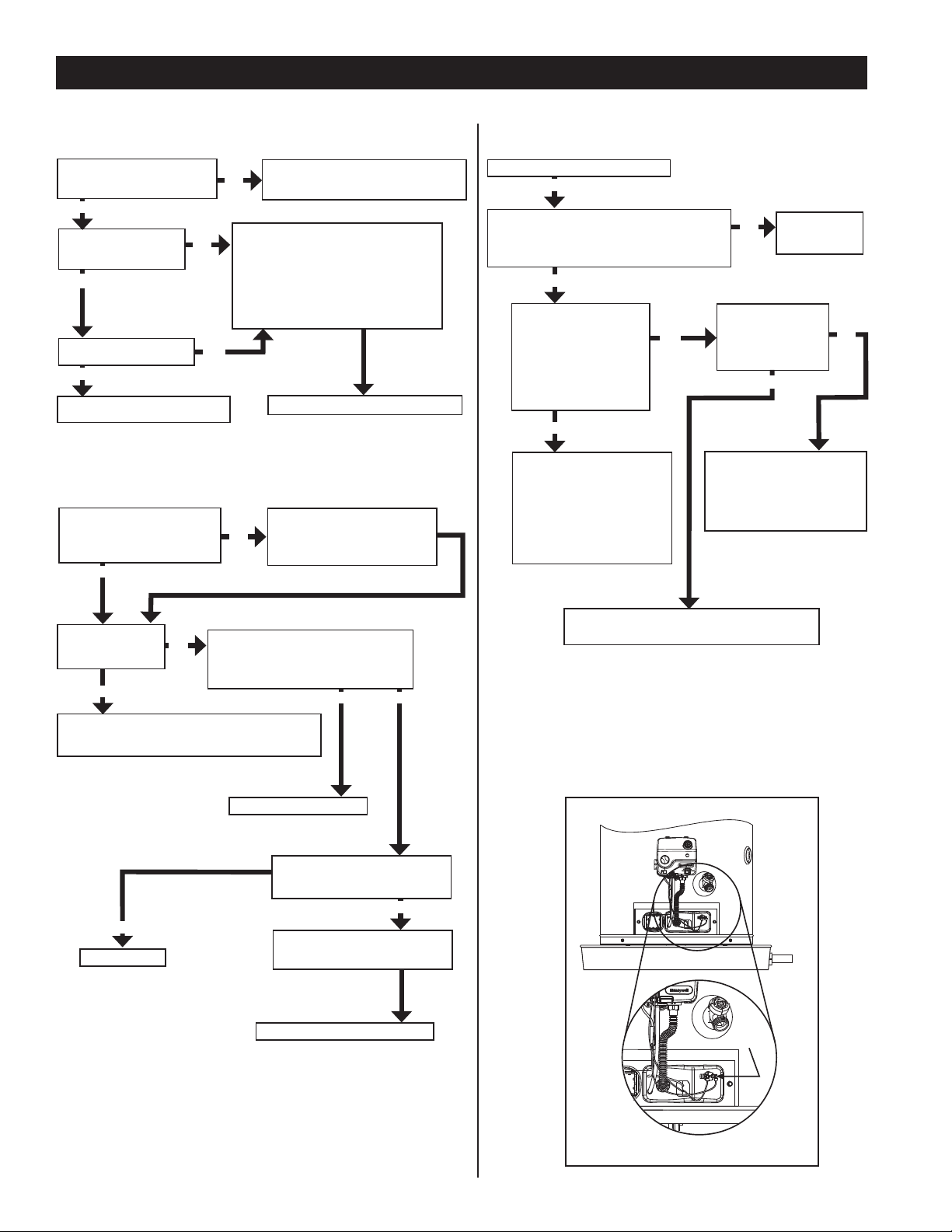
32
PILOT LIGHT TROUBLESHOOTING FLOWCHART
Have you bled all the air
from the pilot tube and
gas supply line?
NO
While repeatedly depressing the igniter
button, push in and hold the gas control/
temperature knob until the pilot is lit and
maintains a stable flame (status light will
blink). It may take up to 90 seconds of
pilot operation before status light blinks.
Once status light blinks, release the gas
control/temperature knob.
Section A: Pilot light will not light (new installation).
Is the manual gas shut-off valve,
located in the supply line to the
water heater, in the on position?
NO
YES
Turn the manual gas shut-off valve to
the on position and follow the lighting
instructions on the front of the water heater.
Is the igniter producing a
spark?
YES
NO
Follow the “Testing the Igniter
System” section in this manual.
Check for insufficient combustion air.
Are the combustion air supply and ventilation
openings of sufficient size? See “Combustion Air
Supply and Ventilation” section in this manual for
requirements.
Does the return air duct
for the furnace/air handler/
air conditioner draw its air
from the same location as
the water heater? See the
“Location Requirements”
section and the “Combustion
Air Supply” section.
Is there proper
drafting at the
drafthood? See
“Checking the Draft”
section in this manual.
Contact a Heating and Air
Conditioning service technician
to relocate the return air duct.
The water heater’s pilot can be
extinguished when the heating
or cooling system is turned on
if the return air duct is in the
same location.
Correct size of
openings to allow
sufficient air.
NO
YES
YES
NO
Section C: Pilot light will not remain lit.
Complete this section after completing Section B.
YES
Set thermostat to desired temperature.
Section B: Pilot light repeatedly goes out.
Check the Base-Ring Filter and
Flame Arrestor for blockage due
to lint or dust. Are both the Air
Filter and Flame Arrestor clean?
Refer to the “Maintenance of
your Water Heater” section of this
manual for information on cleaning
the flame arrestor and burner.
NO
YES
Does the diagnostic status light on the
gas control valve/thermostat give
a two flash error code?
Does the flame
arrestor show signs
of discoloration?
YES
Shut-off the gas supply to the water heater at the
manual gas shut-off valve. Contact Residential
Technical Assistance.
NO
Reassemble the heater, press the thermal
switch, and attempt to return the heater to
service. Does the pilot remain lit?
YES
Set to desired temperature.
NO
YES
Refer to the “Replacing the Pilot/Ther-
mopile Assembly” instructions in the
manual.
Reassemble and restore to service.
Go to section C.
NO
NOTE: If you are still experiencing difficulties after following
the steps in sections A, B, and C, please contact Residential
Technical Assistance.
Check the vent system for
restrictions/obstructions and
check the vent termination
height. Refer to the “Installation
Instructions” section of this
manual for specific requirements.
THERMAL
SWITCH
THERMAL SWITCH LOCATION
FIGURE 31.
YES
If you are still having difficulty keeping the pilot
lit, contact Residential Technical Assistance.
NO
YES

33
NOITCA EVITCERROCMELBORPSUTATS DEL
0 FLASHES (LED NOT LIT) Pilot light is not lit or Thermopile
has not yet reached normal
operating temperature.
Turn Gas Control Valve/Thermostat knob to OFF.
Wait 10 minutes, then attempt to relight Pilot by
following the lighting instructions on the water
heater’s label. Until the Thermopile reaches its
normal operating temperature, the Status Light will
not blink, even if the Pilot is lit. It may take up to 90
seconds of continuous Pilot operation before the
Thermopile reaches normal operating temperature
and the Status Light starts to blink.
If the Status Light does not blink after three lighting
attempts, check to make sure unit is getting gas.
Remove the outer door. Press reset button. Replace
outer door. Turn Gas Control Valve/Thermostat
knob to OFF. Wait 10 minutes, then attempt to light
Pilot by following the lighting instructions on the
water heater’s label. Look through the view port for
the Pilot flame. If Pilot is not visible, the spark igniter
or gas supply to the Pilot should be checked.
If the Pilot is visible and the Status Light does not
blink after
90 seconds of continuous Pilot operation,
the Pilot flame may not be heating the Thermopile
sufficiently (weak Pilot), the Thermopile may be
defective, or wiring connectors may be loose.
NOTE: If the water heater has been operating but
has stopped and will not re-light, check the flame-
arrestor for signs of high temperature (blue or black)
discoloration indicating a flammable vapor incident.
If you suspect a flammable vapor incident has
occurred, do not use this appliance. Immediately
call a qualified technician to inspect the appliance.
Water heaters subjected to a flammable vapors
ignition will require replacement of the entire water
heater.
and the Thermopile is cooling
down.
Turn Gas Control Valve/Thermostat knob to OFF.
Wait 10 minutes for the Thermopile to cool, then
attempt to relight Pilot by following the lighting
instructions on the water heater’s label. NOTE: This
gas control valve/thermostat has built-in circuitry
that requires waiting 10 minutes between lighting
attempts.
Until the Thermopile reaches its normal operating
temperature, the Status Light will not blink, even
if the Pilot is lit. It may take up to 90 seconds of
continuous Pilot operation before the Thermopile
reaches normal operating temperature and the
Status Light starts to blink.
1 FLASH (EVERY 3 SECONDS) Normal operation. No corrective
action necessary.
si elipomrehT eht
tub til si toliPSEHSALF 2
not producing the required output
voltage.
T
urn Gas Control Valve/Thermostat knob to OFF.
The
Thermopile is probably defective, but loose
wiring connections or a weak Pilot flame can also
cause this symptom.
STATUS LIGHT AND DIAGNOSTIC CODE TROUBLESHOOTING CHART
Pilot light was recently extinguished STATUS LIGHT ON (SOLID

34
STATUS LIGHT AND DIAGNOSTIC CODE TROUBLESHOOTING CHART (Continued)
NOITCA EVITCERROCMELBORPSUTATS DEL
4 FLASHES The Gas Control Valve’s
temperature sensor has detected
that the water temperature was too
high. Once this condition occurs,
the Main Burner and the Pilot Light
will be shut off. Since the Pilot light
will be off, should this condition
occur, this Flash Code will only
be displayed immediately after
the Pilot has been relit. Turn Gas
Control Valve/Thermostat knob to
OFF.
Relight pilot and verify 4 flashes. If 4 flashes are
observed, turn Gas Control Valve/Thermostat knob
to OFF. Turn Main Gas Supply OFF. Replace the
Gas Control Valve/Thermostat. See “Removing
and Replacing the Gas Control Valve/Thermostat.”
5 FLASHES The temperature sensor
(thermistor) is defective.
Turn Gas Control Valve/Thermostat knob to OFF.
Replace the temperature sensor (thermistor).
.FFO ot bonk tatsomrehT/evlaV lortnoC saG nruT.eruliaf evlaV lortnoC saGSEHSALF 7
Turn Main Gas Supply OFF. Replace the Gas
Control Valve/Thermostat. See “Removing and
Replacing the Gas
Control V
alve/Thermostat.”
eht fi sraeppa ylno noitidnoc sihTSEHSALF 8
gas control/temperature knob has
been turned off and the thermopile
continued to produce electric
power. This condition can occur
if the thermopile does not cool
down as quickly as expected when
the unit is shut off. This condition
can also occur if the gas control/
temperature knob has been turned
off and the pilot continues to
operate because the pilot valve is
stuck in the open position.
Make sure that the gas control valve/thermostat
knob is set to OFF. Wait one minute. Remove
the outer door. Look through the sight glass for
a pilot flame. If a pilot flame is observed with the
gas control valve/thermostat knob set to the OFF
position, the pilot valve is stuck open. Turn the main
gas supply OFF. Replace the gas control valve/
thermostat. For instructions, see “Removing and
Replacing the Gas Control Valve/Thermostat.”
If the pilot flame is not observed when the gas
control valve/thermostat knob is set to the OFF
position, wait 10 minutes for the thermopile to cool,
then attempt to relight the
pilot by following the
lighting instructions on the water heater’s label. If
this condition returns, replace the gas control valve/
thermostat. See “Removing and Replacing the Gas
Control Valve/Thermostat” for instructions.
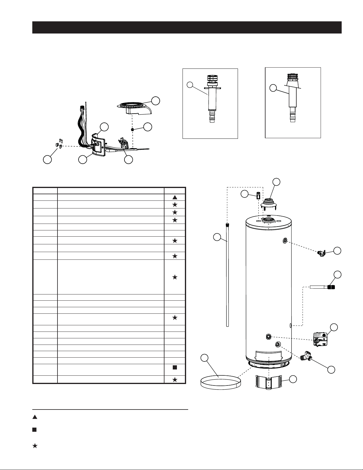
35
REPAIR PARTS ILLUSTRATION
Item No. Part Description
1 Anode Rod
2 Base-Ring Filter
3 Burner Head (natural gas or LP gas)
4 Burner Orifi ce (natural gas or LP gas)
5 Draft Hood
6 Drain Valve
7 Gas Control Valve/Thermostat
8 Inlet Tube w/ Heat Trap
9 Inner Door Gasket
10 Manifold Door Assembly - (natural gas or LP
gas)
Contains: Manifold Tube, Gasket, Door, Pilot Tube,
Thermopile, Manifold Component Block w/ Clip,
Thermal Switch, Burner Head, Burner Orifi ce, and Pilot
Assembly.
11 Mounting Bracket Kit (not shown)
12 Nipple w/Heat Trap
13 Outer Door
14 Pilot Assembly w/ Tubing and
Fittings (natural gas or LP gas)
15 Roof Jack 5-12 Pitch or Less-12” (9002964)
15 Roof Jack 5-12 Pitch or Less-32” (9002965)
15 Roof Jack 5-12 Pitch or Less-60” (9002966)
15 Roof Jack 5-12 Pitch or Less-95” (9002967)
15 Roof Jack 3-12 Pitch or Less-14” (9007941)
15 Roof Jack 3-12 Pitch or Less-30” (9007942)
16 Temperature and Pressure Relief Valve (lo-
cated top or side)
17 Manifold Component Block w/ Clip
3
4
14
9
10
17
12
1
8
16
7
6
13
2
5
VAC
When ordering repair parts always give the following information:
1. Model, serial, and product number
2. Type of gas
3. Item number
4. Parts description
LEGEND
Special anode rod (see Anode Rod Inspection section)
Temperature and Pressure Relief Valve is required, but
may not be factory installed
Unique: FVIR System parts
15
5-12 PITCH OR LESS
15
3-12 PITCH OR LESS

36
Copyright © 2013. All Rights Reserved.
