Owner's Manual
®
HydroSense
Gas Water Heater
FOR POTABLE WATER HEATING ONLY.
NOT SUITABLE FOR SPACE HEATING.
NOT FOR USE IN MOBILE HOMES.
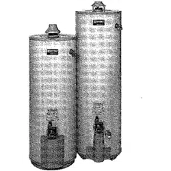
MODEL NO.
153.334430 40 Gallon
153,334530 50 Gallon
, Safety instructions
, installation
, Operation
• Care and Maintenance
• Troubleshooting
• Parts List
For Your Safety
AN ODORANT IS ADDED TO THE GAS USED BY THIS WATER HEATER.
"%
C3 Technology ° Gas Water Heaters meet
the newANSI Z21.10.1 standard that deals
with the accidental or unintended ignition
of flammable vapors, such as those
emitted by gasoline.
Read and understand instruction
manual and safety messages
before installing, operating or
servicing this water heater.
Failure to follow instructions and
safety messages could result in
death or serious injury.
Instruction manual must remain
with water heater.
Si no puede leer o entender el ingles y necesita el manual instructivo
y/o etiquetas en espar_ol puede obtenerlos Ilamando al
1-800-821-2017. NO TRATE DE INSTALAR O OPERAR ESTE
CALENTADOR DEAGUAsi no entiende la informacion en las etiquetas
o en el manual instructivo. No hacer caso de esta advertencia podria
resultar en la MUERTE O GRAVES LESIONES CORPORALES.
WARNING: If the information in these
instructions is not followed exactly, a fire
or explosion may result causing property
damage, personal injury or death.
--Do not store or use gasoline or other
flammable vapors and liquids in the
vicinity of this or any other appliance.
-- WHAT TO DO IF YOU SMELL GAS:
e Do not try to light any appliance.
= Do not touch any electrical switch; do
not use any phone in your building.
e immediately call your gas supplier
from a neighbor's phone. Follow the
gas supplier's instructions.
• if you cannot reach your gas supplier,
cail the fire department.
--Installation and service must be
performed by a qualified installer,
service agency orthe gas supplier.
Sears, Roebuck and Co., Hoffman Estates, IL 60179 U.S.A
PRINTED IN U.S.A. 0806 www.sears.com PART NO. 185614-000

Yoursafetyandthesafetyofothersis extremely important in the installation, use and servicing of this water heater.
Many safety-related messages and instructions have been provided in this manual and on your own water heater to warn you and
others of a potential injury hazard. Read and obey all safety messages and instructions throughout this manual. It is very important
that the meaning of each safety message is understood by you and others who install, use or service this water heater.
This is the safety alert symbol. It is used to alert you to
potential personal injury hazards. Obey all safety
messages that follow this symbol to avoid _ossible
injury or death.
DANGER indicates an irnrninently
hazardous situation which, if not avoided,
could result in death or injury.
WARNING indicates a potentially hazardous
situation which, if not avoided, could result
in death or injury.
CAUTION indicates a potentially hazardous
situation which, if not avoided, may result
in minor or moderate injury.
CAUTION used without the safety alert
symbol indicates a potentially hazardous
situation which, if not avoided, could result
in property damage.
All safety messages will generally tell you about the type of hazard, what can happen if you do not follow the safety message and
how to avoid the risk of injury.
IMPORTANT DEFINITIONS
Gas Supplier: The natural gas or propane utility or service who supplies gas for utilization by the gas burning
appliances within this application, The gas supplier typically has responsibility for the inspection and code approval of
gas piping up to and including the natural gas meter or propane storage tank of a building, Many gas suppliers also
offer service and inspection of appliances within the building,
© Sears, Roebuck and Co.

manual and safety messages
before installing, operating or
servicing this water heater.
Failure to follow instructions and
safety messages could result in
death or serious injury.
Instruction manual must remain
with water heater.
Fire Hazard
For continued protection against
riskof fire:
-Do not install water heater on
carpeted floor.
=Do not operate water heater if
flood damaged.
Water temperature over 125°F
(52°0) can cause severe burns
instantly resulting in severe injury
or death.
Children, the elderly, and the
physically or mentally disabled
are at highest riskfor scald injury.
Feel water before bathing or
showering.
Temperature limiting valves are
available.
Read instruction manual for safe
temperature setting.
Fire or Explosion Hazard
, Do not store or use gasoline or other flammable
vapors and liquids in the vicinity of this or any other
appliance.
• Avoid all ignition sources if you smell LP gas.
• Do not expose water heater control to excessive gas
pressure.
• Use only gas shown on rating plate.
, Maintain required clearances to combustibles.
- Keep ignition sources away from faucets after
,, extended period of non-use.
J
Read instruction manual before
installing, usmg or servlcmg
water heater.
oOverheated water can cause
water tankexplosion.
-Properly sized temperature
and pressure relief valve must
be installed in opening
provided.
Breathing Hazard - Carbon Monoxide Gas
• Install vent system in accordance with
codes.
• Do not operate water heater if flood
damaged.
• High altitude orifice must be installed for
operation above 7,700 feet (2,347 m).
• Do not operate if soot buildup.
• Do not obstruct water heater air intake
with insulating jacket.
• Do not place chemical vapor emitting
products near water heater.
• Gas and carbon monoxide detectors
are available.
Breathing carbon monoxide can cause brain damage or
death. Always read and understand instruction manual
improper installation and use may result
in property damage.
, Do not operate water heater if flood damaged.
• Inspect and replace anode.
- Install in location with drainage.
- Fill tank with water before operation.
• Be alert for thermal expansion.
Refer to instruction manual for installation and service.
SAFEINSTALLATION,USEANDSERVICE.....................................................................................................................................2
SAFETYPRECAUTIONS..................................................................................................................................................................3
TABLEOFCONTENTS.....................................................................................................................................................................4
CUSTOMERRESPONSIBILITIES.....................................................................................................................................................5
PRODUCTSPECIFICATIONS...........................................................................................................................................................5
MATERIALSANDBASICTOOLSNEEDED......................................................................................................................................6
MaterialNeeded..........................................................................................................................................................................6
BasicTools..................................................................................................................................................................................6
TYPICALINSTALLATION..................................................................................................................................................................7
INSTALLATIONINSTRUCTIONS.................................................................................................................................................8-16
RemovingtheOldWaterHeater.................................................................................................................................................8
FactstoConsiderAbouttheLocation....................................................................................................................................9-10
InsulationJackets......................................................................................................................................................................10
CombustionAirandVentilationAppliances
inUnconfinedSpaces................................................................................................................................................................10
CombustionAirandVentilationAppliances
inConfinedSpaces..............................................................................................................................................................11-12
WaterPiping.........................................................................................................................................................................12-13
TemperaturePressureReliefValve......................................................................................................................................13-14
FillingtheWaterHeater............................................................................................................................................................14
Venting.................................................................................................................................................................................14-15
GasPiping............................................................................................................................................................................15-16
SedimentTrap......................................................................................................................................................................16-17
OPERATINGINSTRUCTIONS...................................................................................................................................................18-19
Lighting&OperatingLabel........................................................................................................................................................18
TemperatureRegulation............................................................................................................................................................19
SERVICEANDADJUSTMENT...................................................................................................................................................20-22
Tank(Sediment)Cleaning.........................................................................................................................................................20
VentingSystemInspection........................................................................................................................................................20
BurnerInspection......................................................................................................................................................................20
BurnerCleaning........................................................................................................................................................................20
Housekeeping......................................................................................................................................................................20-21
AnodeRodInspection...............................................................................................................................................................21
Temperature-PressureReliefValveOperation..........................................................................................................................21
Draining................................................................................................................................................................................21-22
DrainValveWasherReplacement............................................................................................................................................22
Service.......................................................................................................................................................................................22
StartUpConditions..............................................................................................................................................................23-24
ThermalExpansion.............................................................................................................................................................23
StrangeSounds..................................................................................................................................................................23
DraftHoodOperation.....................................................................................................................................................23-24
Condensation......................................................................................................................................................................24
Smoke/Odor........................................................................................................................................................................24
OperationalConditions.........................................................................................................................................................24-25
SmellyOdor........................................................................................................................................................................24
AirinHotWaterFaucets.....................................................................................................................................................25
HighTemperatureShut-OffSystem....................................................................................................................................24
LeakageCheckpoints.........................................................................................................................................................25
SERVICEINSTRUCTIONSFORGASCONTROLVALVEASSEMBLY.....................................................................................26-27
TROUBLESHOOTINGGUIDE....................................................................................................................................................28-29
PARTSORDERLIST.......................................................................................................................................................................30
NOTES.............................................................................................................................................................................................31
WARRANTY.....................................................................................................................................................................................32
ThankYouforpurchasingaKenmorewaterheater.Properly
installedandmaintained,itshouldgiveyouyearsoftroublefree
service.Ifyoushoulddecidethatyouwantthenewwaterheater
professionallyinstalledbySearscall1-800-4-MY-HOME_LThey
willarrangeforprompt,qualityinstallationbySearsauthorized
contractors.
AbbreviationsFoundInThis Instruction Manual:
CSA - Canadian Standards Association
ANSI -American National Standards Institute
NFPA - National Fire Protection Association
ASME - American Society of Mechanical Engineers
GAMA - Gas Appliance Manufacturers Association
This gas-fired water heater is design certified by CSA
INTERNATIONAL under American National Standard/CSA
Standard for Gas Water Heaters ANSI Z21.10.1 • CSA 4.1
(current edition).
Read the "Safety Precautions" section, page 3 of this manual
first and then the entire manual carefully. If you don't follow
the safety rules, the water heater will not operate properly. It
could cause DEATH, SERIOUS BODILY INJURY AND/OR
PROPERTY DAMAGE.
This manual contains instructions for the installation, operation,
and maintenance of the gas-fired water heater. It also contains
warnings through out the manual that you must read and be
aware of. All warnings and all instructions are essential to the
proper operation of the water heater and your safety. Since
we cannot put everything on the first few pages, READ THE
ENTIRE MANUAL BEFORE ATTEMPTING TO INSTALL OR
OPERATE THE WATER HEATER.
The installation must conform with these instructions and the
local code authority having jurisdiction. In the absence of
local codes, installations shall comply with the following:
The National Fuel Gas Code ANSI Z223.1/NFPA 54. This
publication is available from the Canadian Standards
Association, 8501 East Pleasant Valley Rd, Cleveland Ohio
44131, or The National Fire Protection Association,
1 Batterymarch Park, Quincy, MA 02269.
If after reading this manual you have any questions or do not
understand any portion of the instructions, call the Sears
Service Center.
Carefully plan the place where you are going to put the water
heater. Correct combustion, vent action, and vent pipe
installation are very important in preventing death from
possible carbon monoxide poisoning and fires. See
figure 1.
Examine the location to ensure the water heater complies
with the Facts to Consider About the Location section in this
manual.
For California installation this water heater must be braced,
anchored, or strapped to avoid falling or moving during an
earthquake. See instructions for correct installation
procedures. Instructions may be obtained from your local
dealer, wholesaler, public utilities or California Office of the
State Architect, 400 P Street, Sacramento, CA 95814.
Massachusetts Code requires this water heater to be installed
in accordance with Massachusetts 248-CMR 2.00: State
Plumbing Code and 248-CMR 5.00.
Complies with SCAQMD rule #1121 and districts having
equivalent NOx requirements.
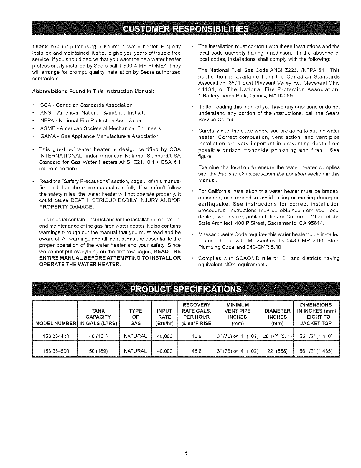
RECOVERY MINIMUM DIMENSIONS
TANK TYPE INPUT RATE GALS. VENT PIPE DIAMETER IN INCHES (ram)
CAPACITY OF RATE PER HOUR INCHES INCHES HEIGHT TO
MODEL NUMBER IN GALS (LTRS) GAS (Btu/hr) @ 90°F RISE (ram) (ram) JACKET TOP
153.334430 40 (151) NATURAL 40,000 46.9 3" (76) or 4" (102) 20 I/2" (521) 55 I/2" (1,410)
153.334530 50 (I89) NATURAL 40,000 45.8 3" (76) or 4" (102) 22" (558) 56 1/2" (1,435)

Materials Needed
To simplify the installation Sears has available the installation parts shown below. You may or may not need all of these materials,
depending on your type of installation.
EXPANSION TANKS FOR
THERMAL EXPANSION
CONDITIONS AVAILABLE
IN 2 GALLONS
(7.6 LITERS) AND
5 GALLONS (18,9 LITERS)
CAPACITY HROUGH
LOCAL SEARS STORE
OR SERVICE CENTER.
WATER HEATER INSTALLATION KIT WITH
FLEXIBLE CONNECTORS FOR 3/4"
(19.05 mm) OR 1/2" (12,7 ram) THREADED OR
COPPER PLUMBING AND FLEXIBLE WATER
HEATER GAS CONNECTOR WITH FITTINGS.
I ' 'k ,
DRAIN PANS AVAILABLE IN
20" (508 ram) DIAMETER FOR
WATER HEATERS HAVING A
DIAMETER 18" (457 ram) OR
LESS, 24" (610ram) DIAMETER
FOR WATER HEATERS HAVING
A DIAMETER 22" (559 ram) OR
LESS AND AVAILABLE IN 28"
(711 mm) DIAMETER FOR
WATER HEATERS HAVING A
DIAMETER 26" (660 ram) OR
LESS.
Basic Tools
You may or may not need all these tools, depending on your
type of installation. These tools can be purchased at your local
Sears Store.
Pipe Wrenches (2) 14" (356 mm) __
Screwdriver
Tin Snips
6' (1.82 m) Tape or Folding Ruler
Garden Hose
Drill
Pipe Dope or Teflon Tape DRILL
SLOT-HEAD SCREWDRIVER
PHILLIPS SCREWDRIVER
TIN SNIPS
ROLL OFTEFLON
TAPE (USE ONLYON
WATER CONNECTIONS)
PIPE DOPE
(SQUEEZE TUBE)
USE FOR WATERAND GAS
CONNECTIONS
GARDEN HOSE 6 FOOT TAPE PIPE WRENCH
Additional Tools Needed
When Sweat Soldering
Tubing Cutters or Hacksaw
Propane Tank
Soft Solder
Solder Flux
Emery Cloth
Wire Brushes
TUBING CUTTER
PROPANE
TORCH
HACKSAW
ROLL OF
EMERY CLOTH
3/4" (19 ram) WIRE BRUSH
1/2" (13 ram) WIRE BRUSH
ROLL OF LEAD-FREE
SOFT SOLDER
SOLDER
FLUX

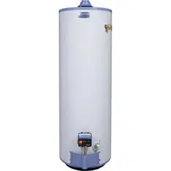
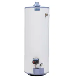
GET TO KNOW YOUR WATER HEATER - GAS MODELS
A Vent Pipe J Drip Leg (Sediment Trap) S FlueBaffle
B Draft Hood K inner Door T Thermostat
C Anode L Outer door U Drain Valve
D Hot Water Outlet M Union V Pilot and Main Burner
E Outlet N inlet Water Shut-off Valve W Flue
F Flexible Water Connections O Cold Water inlet X Drain Pan
G GasSupply P inlet Dip Tube Y Piezolgniter
H ManuaIGasShut-offVaive Q Temperature-Pressure Relief Valve Z Air intake Screen
I Ground Joint Union R Rating Plate
* iNSTALL iN ACCORDANCE
WITH LOCAL CODES.
* DRIP LEG AS REQUIRED
BY LOCAL CODES.
TO VENT TERMINATION
ON ROOF
B
D
\
iNSTALL THERMAL EXPANSION
TANK OR DEVICE IF WATER
HEATER iS iNSTALLED IN A
CLOSED WATERSYSTEM
W
R
\
VACUUM REUEF
VALVE
(T) THERMOSTAT
(V) PILOT & MAiN BURNER
BURNER
THERMOPILE PILOT
BURNER
iGNiTER
PILOT
TUBING
MAiN
BURNER
THERMOPILE
TCO
*ALL PIPING MATERIALS TO BE
SUPPLIED BY CUSTOMERS. FIGURE 1.
7

Removing the Old Water Heater
® ® ®
G
FIGURE 2.
Q Turn "OFF" the gas supply to the
water heater.
If the main gas line shut-off valve
serving all gas appliances is used,
also shut "OFF" the gas at each
appliance. Leave all gas
appliances shut "OFF" until the
water heater installation is
completed, see Figures 2 and 3.
FIGURE 3.
Q Turn "OFF" the water to the
supply
water heater at the water shut-off
valve or water meter. Some
installations require that the water
be turned off to the entire house,
see Figures 2 and 4.
FIGURE 4.
Check to make the is "OFF" to the
again
sure
gas
supply
water heater. Then disconnect the gas supply connection from
the gas control valve.
, Burn hazard
, Hotwater discharge.
, Keep hands clear of drain
valve discharge.
Q Attach a to water
hose the heater
drain valve and put the other end
in a floor drain or outdoors. Open
the water heater drain valve. Open
a nearby hot water faucet which will
relieve pressure in the water heater
and speed draining. The water
passing out of the drain valve may
be extremely hot. To avoid being
scalded, make sure all connections
are tight and that the water flow is
directed away from any person, see
Figures 2 and 5. FIGURE 5,
(_. Disconnect the from the draft hood where it
vent
pipe
connects
to the water heater. In most installations the vent pipe can
be lifted off after any screw or other attached devices are
removed. Dispose of the draft hood. The new water heater
has a draft hood which must be used for proper operation.
Q If you copper piping to water heater, two copper
have the the
water pipes can be cut with a hacksaw approximately four
inches away from where they connect to the water heater,
see Figure 6. This will avoid cutting off pipes too short.
Additional cuts can be made later if necessary. Disconnect
the temperature-pressure relief valve drain line. When the
water heater is drained, disconnect the hose from the drain
valve. Close the drain valve. The water heater is now
completely disconnected and ready to be removed.
FIGURE 6.
If you have galvanized pipes to the water heater, loosen the
two galvanized pipes with a pipe wrench at the union in each
line. Also disconnect the piping remaining to the water heater,
see Figure 7. These pieces should be saved since they may
be needed when reconnecting the new water heater.
Disconnect the temperature-pressure relief valve drain line.
When the water heater is drained, disconnect the hose from
the drain valve. Close the drain valve. The water heater is
now completely disconnected and ready to be removed.
Mineral buildup or sediment may have accumulated in the
old water heater. This causes the water heater to be much
heavier than normal and this residue, if spilled out, could cause
staining.
FIGURE 7.

Facts to Consider About
the Location
Carefully choose an indoor location for the new water heater,
because the placement is a very important consideration for the
safety of the occupants in the building and for the most
economical use of the appliance. This water heater is not for
use in manufactured (mobile) homes or outdoor installation.
Whether replacing an old water heater or putting the water heater
in a new location, the following critical points must be observed:
Select a location indoors as close as practical to the gas vent
or chimney to which the water heater vent is going to be
connected, and as centralized with the water piping system
as possible.
• Selected location must provide adequate clearances for
servicing and proper operation of the water heater.
Property Damage Hazard
, All water heaters eventually leak
• Do notinstallwithout adequate drainage.
Installation of the water heater must be accomplished in such a
manner that if the tank or any connections should leak, the flow
will not cause damage to the structure. For this reason, it is not
advisable to install the water heater in an attic or upper floor.
When such locations cannot be avoided, a suitable drain pan
should be installed under the water heater. Drain pans are
available at your local Sears or hardware store. Such a drain
pan must have a minimum length and width of at least 2 inches
(51 mm) greater that the water heater dimensions and must be
piped to an adequate drain. The pan must not restrict combustion
air flow.
Water heater life depends upon water quality, water pressure
and the environment in which the water heater is installed. Water
heaters are sometimes installed in locations where leakage may
result in property damage, even with the use of a drain pan piped
to a drain. However, unanticipated damage can be reduced or
prevented by a leak detector or water shut-off device used in
conjunction with a piped drain pan. These devices are available
from some plumbing supply wholesalers and retailers, and detect
and react to leakage in various ways:
• Sensors mounted in the drain pan that trigger an alarm or
turn off the incoming water to the water heater when leakage
is detected.
• Sensors mounted in the drain pan that turn off the water supply
to the entire home when water is detected in the drain pan.
• Water supply shut-off devices that activate based on the water
pressure differential between the cold water and hot water
pipes connected to the water heater.
Devices that will turn off the gas supply to a gas water heater
while at the same time shutting off its water supply.
Fire or Explosion Hazard
* Do not store or use gasoline or other flammable
vapors and liquids in the vicinity of this or any other
appliance.
, Avoid all ignition sources if you smell LP gas.
, Do not expose water heater control to excessive gas
pressure.
- Use only gas shown on rating plate.
- Maintain required clearances to combustibles.
. Keep ignition sources away from faucets after
_, extended period of non-use.
Read instruction manual before
installing, using or servicing
water heater.
INSTALLATIONS IN AREAS WHERE FLAMMABLE LIQUIDS
(VAPORS) ARE LIKELY TO BE PRESENT OR STORED
(GARAGES, STORAGE AND UTILITY AREAS, ETC.):
Flammable liquids (such as gasoline, solvents, propane [LP or
butane, etc.] and other substances such as adhesives, etc.) emit
flammable vapors which can be ignited by a gas water heater's
pilot light or main burner. The resulting flashback and fire can
cause death or serious burns to anyone in the area. Even though
this water heater is a flammable vapors ignition resistant water
heater and is designed to reduce the chances of flammable
vapors being ignited, gasoline and other flammable substances
should never be stored or used in the same vicinity or area
containing a gas water heater or other open flame or spark
producing appliance.
Also, the water heater must be located and/or protected so it is
not subject to physical damage by a moving vehicle.
Fire Hazard
For continued protection against
risk of fire:
• Do not install water heater on
carpeted floor.
. Do not operate water heater if
flood damaged.
This water heater must not be installed directly on carpeting.
Carpeting must be protected by metal or wood panel beneath
the appliance extending beyond the full width and depth of the
appliance by at least 3 inches (76.2mm) in any direction, or if the
appliance is installed in an alcove or closet, the entire floor must
be covered by the panel. Failure to heed this warning may result
in a fire hazard.

Fire or Explosion Hazard
Read instruction manual before installing,
• Improper use may result in fire or
explosion.
-Maintain required clearances to
combustibles.
Minimum clearances between the water heater and combustible
construction are 0 inch at the sides and rear,
4 inches (102 mm) at the front, and 6 inches (153 mm) from the
vent pipe, see Figure 8. Clearance from the top of the jacket is 12
inches (305 mm) on most models. Note that a lesser dimension
may be allowed on some models, refer to the label attached
adjacent to the gas control valve on the water heater.
FIGURE 8.
Breathing Hazard - Carbon Monoxide Gas
|
- Install water heater in accordance
with the instruction manual and
NFRA 54.
- To avoid injury, combustion and
ventilation air must be taken from
outdoors.
• Do not place chemical vapor
emitting products near water
heater.
Breathing carbon monoxide can cause brain damage or
death. Always read and understand instruction manual.
__12" MAX. (3{)cm)
VENTiLATiON
AIR
OPENINGO
FRONT ViEW
OF DOOR
JL 12" MAX.
t (30cm)
3-MIN.
J( .z.,ml
AiR DUCT
FIGURE 9.
If this water heater will be used in beauty shops, barber shops,
cleaning establishments, or self-service laundries with dry
cleaning equipment, it is imperative that the water heater or water
heaters be installed so that combustion and ventilation air be
taken directly from outdoors (direct vent).
Propellants of aerosol sprays and volatile compounds, (cleaners,
chlorine based chemicals, refrigerants, etc.) in addition to being
highly flammable in many cases, will also change to corrosive
hydrochloric acid when exposed to the combustion products of
the water heater. The results can be hazardous, and also cause
product failure.
Insulation Blankets
Insulation blankets available to the general public for external
use on gas water heaters are not necessary with Kenmore
products. The purpose of an insulation blanket is to reduce the
standby heat loss encountered with storage tank heaters. Your
Kenmore water heater meets or exceeds the National Appliance
Energy Conservation Act standards with respect to insulation
and standby loss requirements, making an insulation blanket
unnecessary.
Breathing Hazard - Carbon Monoxide Gas
• Do not obstruct water heater air
intake with insulating blanket.
• Gas and carbon monoxide detectors
are available
• Install water heater in accordance
with the instruction manual.
Breathing carbon monoxide can cause brain damage or
death. Always read and understand instruction manual.
A gas water heater cannot operate properly without the correct
amount of air for combustion, see Figure 9. Do not install in a
confined area such as a closet, unless you provide air as shown
in the Locating The New Water Heater section. Never obstruct
the flow of ventilation air. If you have any doubts or questions at
all, call your gas supplier. Failure to provide the proper amount
of combustion air can result in a fire or explosion and cause
death, serious bodily injury, or property damage.
_ WARNING
Should you choose to apply an insulation blanket to this heater,
you should follow these instructions (See Figure 1 for
identification of components mentioned below). Failure to follow
these instructions can restrict the air flow required for proper
combustion, potentially resulting in fire, asphyxiation, serious
personal injury or death.
10
Donotapplyinsulationtothetopofthewaterheater,asthis
willinterferewithsafeoperationofthedrafthood.
Donotcovertheouterdoor,thermostatortemperature&
pressurereliefvalve.
Donotallowinsulationtocomewithin2"(50.8mm)ofthe
floortopreventblockageofcombustionairflowtotheburner.
Donotcovertheinstructionmanual.Keepitonthesideof
thewaterheaterornearbyforfuturereference.
DoobtainnewwarningandinstructionlabelsfromSearsfor
placementontheblanketdirectlyovertheexistinglabels.
Doinspecttheinsulationblanketfrequentlytomakecertain
itdoesnotsag,therebyobstructingcombustionairflow.
commencewithin12inches(30cm)ofthetopandone
commencingwithin12inches(30cm)ofthebottomofthe
enclosures.
CHIIVINEY OR GAS VENT
Combustion Air and Ventilation for
Appliances Located in Unconfined Spaces
UNCONFINED SPACE is space whose volume is not less than
50 cubic feet per 1,000 Btu per hour (4.8 m3 per kW) of the
aggregate input rating of all appliances installed in that space.
Rooms communicating directly with the space in which the
appliances are installed, through openings not furnished with
doors, are considered a part of the unconfined space.
In unconfined spaces in buildings, infiltration may be adequate
to provide air for combustion, ventilation and dilution of flue
gases. However, in buildings of tight construction (for example,
weather stripping, heavily insulated, caulked, vapor barrier, etc.),
additional air may need to be provided using the methods
described in Combustion Air and Ventilation for Appliances
Located in Confined Spaces.
Combustion Air and Ventilation for
Appliances Located in Confined Spaces
CONFINED SPACE is a space whose volume is less than
50 cubic feet per 1,000 Btu per hour (4.8 m 3 per kW) of the
aggregate input rating of all appliances installed in that space.
A. ALLAIR FROM INSIDE BUILDINGS:
(See Figure 9 on page 9 and Figure 10 below)
The confined space shall be provided with two permanent
openings communicating directly with an additional room(s)
of sufficient volume so that the combined volume of all spaces
meets the criteria for an unconfined space. The total input of
all gas utilization equipment installed in the combined space
shall be considered in making this determination. Each
opening shall have a minimum free area of one square inch
per 1,000 Btu per hour (22 cm2/kW) of the total input rating of
all gas utilization equipment in the confined space, but not
less than 100 square inches (645 cm2). One opening shall
FIGURE 10.
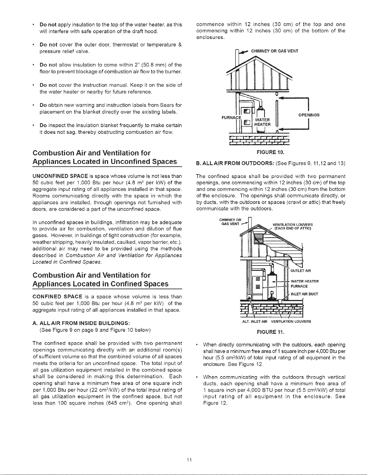
B. ALL AiR FROM OUTDOORS: (See Figures 9, 11,12 and 13)
The confined space shall be provided with two permanent
openings, one commencing within 12 inches (30 cm) of the top
and one commencing within 12 inches (30 cm) from the bottom
of the enclosure. The openings shall communicate directly, or
by ducts, with the outdoors or spaces (crawl or attic) that freely
communicate with the outdoors.
CHIMNEY OR
GAS VENT
VENTiLATiON LOUVERS
OUTLET AiR
, WATER HEATER
FURNACE
• iNLET AiR DUCT
ALT. INLETAIR VENTiLATiON LOUVERS
FIGURE 11.
When directly communicating with the outdoors, each opening
shall have a minimum free area of 1 square inch per 4,000 Btu per
hour (5.5 cm2/kW) of total input rating of all equipment in the
enclosure. See Figure 12.
When communicating with the outdoors through vertical
ducts, each opening shall have a minimum free area of
1 square inch per 4,000 BTU per hour (5.5 cm2/kW) of total
input rating of all equipment in the enclosure. See
Figure 12.
11

VENTILATION LOUVERS
OUTLET
HEATER
"FURNACE
iNLET AiR DUCT
{ENDS 1' OR 30 cm
ABOVE FLOOR)
FIGURE 12.
When communicating with the outdoors through horizontal
ducts, each opening shall have a minimum free area of 1
square inch per 2,000 BTU per hour (11 cm2/kW) of total
input rating of all equipment in the enclosure. See
Figure 13.
When ducts are used, they shall be of the same cross-
sectional area as the free area of the openings to which they
connect. The minimum short side dimension of rectangular
air ducts shall not be less than 3 inches
(76.2 mm). See Figure 13.
_i__ a_ CHIMNEY OR GAS VENT
__W_ _ OUTLET AIR DUCT
FURNA II
FIGURE 13.
Louvers and Grilles: In calculating free area, consideration
shall be given to the blocking effect of louvers, grilles or
screens protecting openings. Screens used shall not be
smaller than 1/4 inch (6.4 mm) mesh. If the free area through
a design of louver or grille is known, it should be used in
calculating the size opening required to provide the free area
specified. If the design and free area is not known, it may be
assumed that wood louvers will be 20-25 percent free area
and metal louvers and grilles will have 60-75 percent free
area. Louvers and grilles shall be fixed in the open position
or interlocked with the equipment so that they are opened
automatically during equipment operation.
Special Conditions Created by Mechanical Exhausting or
Fireplaces: operation of exhaust fans, ventilation systems,
clothes dryers or fireplaces may create conditions requiring
special attention to avoid unsatisfactory operation of installed
gas utilization equipment.
Water Piping
Water temperature over 125°F
(52°C) can cause severe burns
instantly resulting in severe injury
or death.
Children, elderly, and the
physically or mentally disabled
are at highest riskfor scald injury.
Feel water before bathing or
showering.
Temperature limiting valves are
available.
Read instruction manual for safe
temperature setting.
HOTTER WATER CAN SCALD:
Water heaters are intended to produce hot water. Water heated
to a temperature which will satisfy space heating, clothes
washing, dish washing, cleaning and other sanitizing needs
can scald and permanently injure you upon contact. Some
people are more likely to be permanently injured by hot water
than others. These include the elderly, children, the infirm, or
physically/mentally handicapped. If anyone using hot water in
your home fits into one of these groups or if there is a local
code or state law requiring a certain temperature water at the
hot water tap, then you must take special precautions. In
addition to using the lowest possible temperature setting that
satisfies your hot water needs, a means such as a *mixing
valve, shall be used at the hot water taps used by these people
or at the water heater. Mixing valves are available at plumbing
supply or hardware stores. See Figure 14. Valves for reducing
point of use temperature by mixing cold and hot water are also
available. Follow manufacturer's instructions for installation of
the valves. Before changing the factory setting on the
thermostat, read the Temperature Regulation section in this
manual.
HOT WATER _ COLD WATER
OUTLET ] IN__LET
TEMPERE[_o
WATER OUTLET
LD WATER
T iNLET ON
ERb. ' WA%.EATER
*MIXING HOT WATER
VALVE OUTLET ON
WATER HEATER
RGURE 14,
Toxic Chemical Hazard
• Do not connect to non-potable water system.
12
Thiswaterheatershallnotbeconnectedtoanyheatingsystems
orcomponent(s)usedwitha non-potablewaterheating
appliance.
Allpipingcomponentsconnectedtothisunitforspaceheating
applicationsshallbesuitableforusewithpotablewater.
Lookatthetopofthewaterheater.Thecoldwaterinletis
marked"COLD".Puttwoorthreeturnsofteflontapearound
thethreadedendofthethreaded-to-sweatcouplingand
aroundbothendsofthe3/4"NPTthreadednipple.Using
flexibleconnectors,connectthecoldwaterpipetothecold
waterinletofthewaterheater.
Toxicchemicals,suchasthoseusedforboilertreatmentshall
notbeintroducedintothissystem.
Watersupplysystemsmay,becauseofsucheventsashigh
linepressure,frequentcut-offsortheeffectsofwaterhammer
amongothers,haveinstalleddevicessuchaspressurereducing
valves,checkvalves,backflowpreventers,etc.tocontrolthese
typesofproblems.Whenthesedevicesarenotequippedwith
aninternalby-pass,andnoothermeasuresaretaken,the
devicescausethewatersystemtobeclosed.Aswaterisheated,
itexpands(thermalexpansion)andclosedsystemsdonotallow
fortheexpansionofheatedwater.
Thewaterwithinthewaterheatertankexpandsasitisheated
andincreasesthepressureofthewatersystem.Iftherelieving
pointofthewaterheater'stemperature-pressurereliefvalveis
reached,thevalvewillrelievetheexcesspressure.The
temperature-pressurerelief valve is not intended for the
constant relief of thermal expansion. This is an unacceptable
condition and must be corrected. It is recommended that any
devices installed which could create a closed system have a
by-pass and/or the system have an expansion tank to relieve
the pressure built by thermal expansion in the water system.
Refer to the Thermal Expansion section under Troubleshooting
Guide or contact local plumbing authority or local Sears Service
Center on how to control this situation.
NOTE: To protect against untimely corrosion of hot and cold
water fittings, it is strongly recommended that di-electric
unions or couplings be installed on this water heater when
connected to copper pipe.
Property Damage Hazard
• Avoid water heater damage.
- Install thermal expansion tank if necessary.
• Do not apply heat to cold water inlet.
• Contact qualified installer or Sears Service Center.
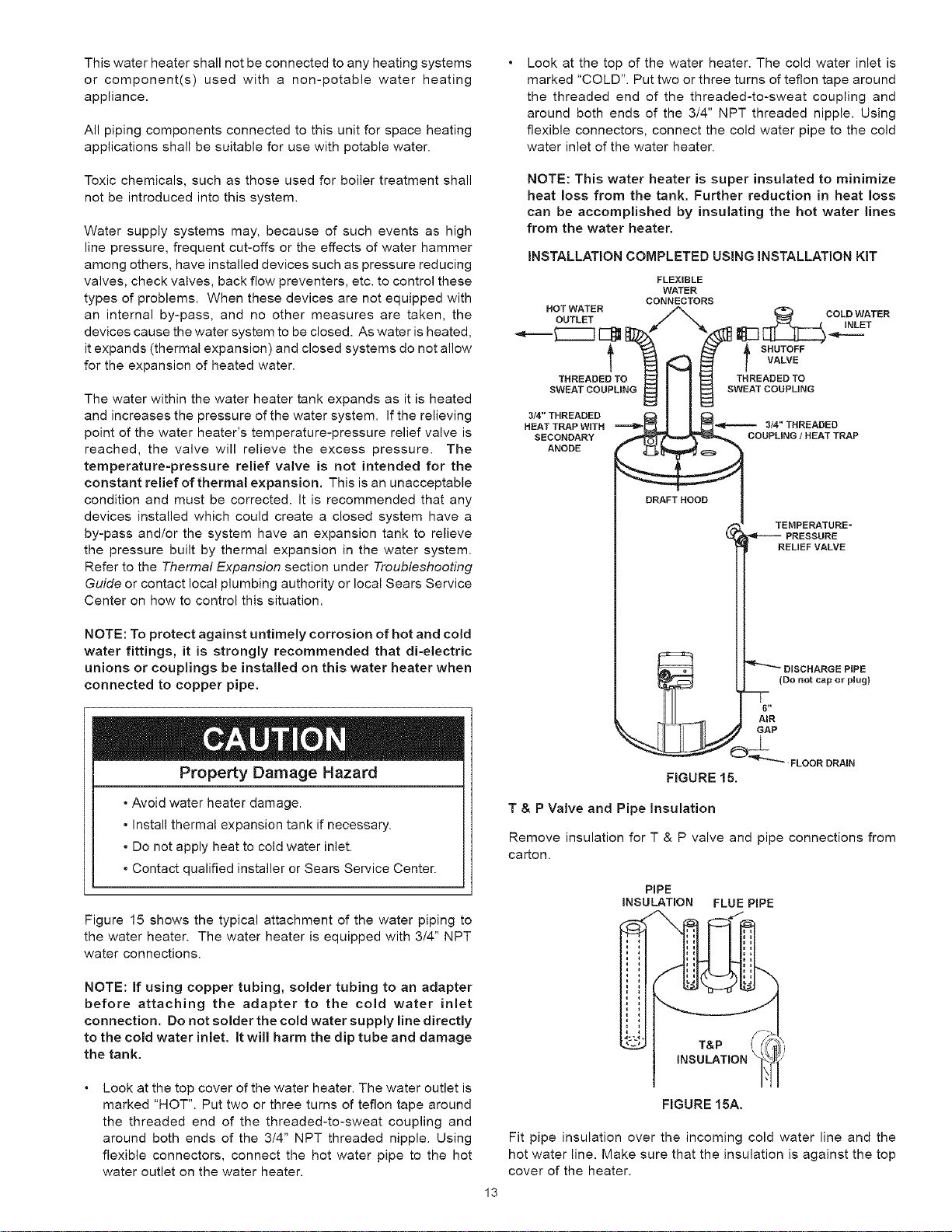
Figure 15 shows the typical attachment of the water piping to
the water heater. The water heater is equipped with 3/4" NPT
water connections.
NOTE: If using copper tubing, solder tubing to an adapter
before attaching the adapter to the cold water inlet
connection, Do not solder the cold water supply line directly
to the cold water inlet, it will harm the dip tube and damage
the tank.
Look at the top cover of the water heater. The water outlet is
marked "HOT". Put two or three turns of teflon tape around
the threaded end of the threaded-to-sweat coupling and
around both ends of the 3/4" NPT threaded nipple. Using
flexible connectors, connect the hot water pipe to the hot
water outlet on the water heater.
NOTE: This water heater is super insulated to minimize
heat loss from the tank. Further reduction in heat loss
can be accomplished by insulating the hot water lines
from the water heater.
INSTALLATION COMPLETED USING INSTALLATION KIT
FLEXIBLE
WATER
CONNECTORS
HOT WATER COLD WATER
OUTLET INLET
I _ I sHUTOFF
VALVE
THREADED TO THREADED TO
SWEAT COUPLING SWEAT COUPLING
3/4"THREADED
HEAT TRAP WITH """"1_ _ 3/4'*THREADED
SECONDARY COUPLING/HEATTRAP
ANODE
DRAFT HOOD
FIGURE 15.
TEMPERATURE -
PRESSURE
RELIEF VALVE
_'_ DmSCHARGE PIPE
(Do not cap or plug)
6"
AmR
GAP
_" FLOOR DRAIN
T & P Valve and Pipe Insulation
Remove insulation for T & P valve and pipe connections from
carton.
PiPE
iNSULATiON FLUE PiPE
= t
E t
FIGURE 15A.
Fit pipe insulation over the incoming cold water line and the
hot water line. Make sure that the insulation is against the top
cover of the heater.
13

FitT&Pvalveinsulationovervalve.Makesurethattheinsulation
doesnotinterferewiththeleveroftheT&Pvalve.
Secureallinsulationusingtape.
Temperatu re=Pressu re Relief Valve
/---\
E×plosion Hazard
• Temperature-pressure relief valve
must comply with ANSI Z2122
and ASME code.
• Properly sized temperature-
pressure relief valve must be
installed in opening provided.
-Can result in overheating and
ezcessive tank pressure
• Can cause serious injury or death.
HOT WATER
DRAFT HOOD
TEMPERATURE-PRESSUI
_ RELIEF VALVE
(OPTIONAL TOP T & P REL
VALVE NOT SHOWN)
DISNCARGE PiPE
(DO NOT CAP OR PLUG)
DRAIN VALVE
FLOOR DRAIN
This heater is provided with a properly certified combination
temperature - pressure relief valve by the manufacturer.
The valve is certified by a nationally recognized testing laboratory
that maintains periodic inspection of production of listed
equipment as meeting the requirements for Relief Valves and
Automatic Gas Shutoff Devices for Hot Water Supply Systems,
ANSI Z21.22 and the code requirements of ASME.
If replaced, the valve must meet the requirements of local
codes, but not less than a combination temperature and
pressure relief valve certified as indicated in the above
paragraph.
The valve must be marked with a maximum set pressure not
to exceed the marked hydrostatic working pressure of the
water heater (150 psi = 1,035 kPa) and a discharge capacity
not less than the water heater input rate as shown on the
model rating plate.
For safe operation of the water heater, the relief valve must not
be removed from its designated opening nor plugged.
The temperature-pressure relief valve must be installed directly
into the fitting of the water heater designed for the relief valve.
Position the valve downward and provide tubing so that any
discharge will exit only within 6 inches (153 mm) above, or at
any distance below the structural floor, see Figure 16. Be certain
that no contact is made with any live electrical part. The
discharge opening must not be blocked or reduced in size under
any circumstances. Excessive length, over 30 feet
(9.14 m), or use of more than four elbows can cause restriction
and reduce the discharge capacity of the valve.
No valve or other obstruction is to be placed between the relief
valve and the tank. Do not connect tubing directly to discharge
drain unless a 6 inch air gap is provided. To prevent bodily
injury, hazard to life, or property damage, the relief valve must
be allowed to discharge water in quantities should circumstances
demand. If the discharge pipe is not connected to a drain or
other suitable means, the water flow may cause property
damage.
FIGURE 16.
Water Damage Hazard
* Temperature-pressure relief valve discharge
pipe must terminate at adequate drain.
The Discharge Pipe:
• Shall not be smaller in size than the outlet pipe size of the
valve, or have any reducing couplings or other restrictions.
• Shall not be plugged or blocked.
• Shall be of material listed for hot water distribution.
• Shall be installed so as to allow complete drainage of both
the temperature-pressure relief valve, and the discharge
pipe.
• Shall terminate at an adequate drain.
• Shall not have any valve between the relief valve and tank.
Water temperature over 125°F
(52°C) can cause severe burns
instantly resulting in severe injury
or death.
Children, the elderly, and the
physically or mentally disabled
are at highest riskforscald injury.
Feel water before bathing or
showering.
Temperature limiting valves are
available.
Read instruction manual for safe
temperature setting.
14
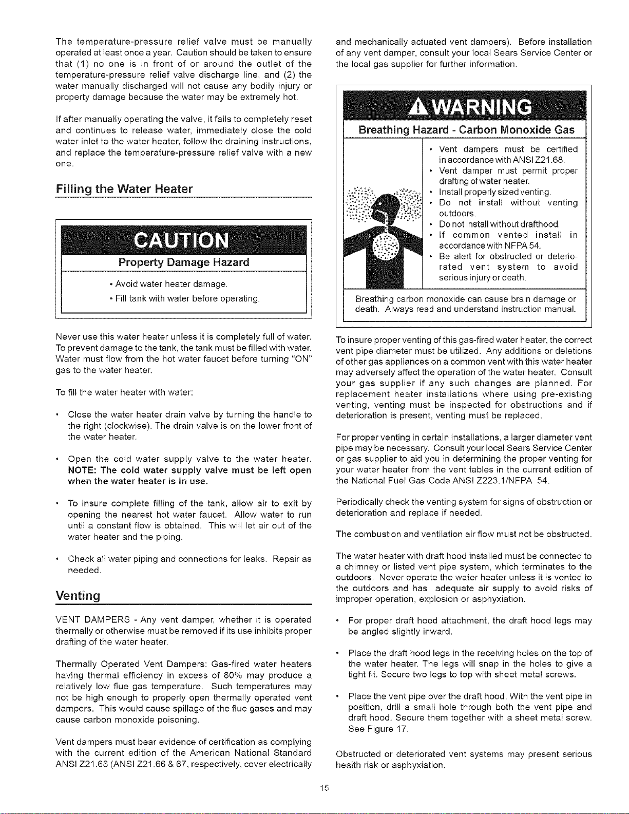
Thetemperature-pressurereliefvalvemustbemanually
operatedatleastonceayear.Cautionshouldbetakentoensure
that(1)nooneisinfrontoforaroundtheoutletofthe
temperature-pressurereliefvalvedischargeline,and(2)the
watermanuallydischargedwillnotcauseanybodilyinjuryor
propertydamagebecausethewatermaybeextremelyhot.
Ifaftermanuallyoperatingthevalve,itfailstocompletelyreset
andcontinuesto releasewater,immediatelyclosethecold
waterinlettothewaterheater,followthedraininginstructions,
andreplacethetemperature-pressurereliefvalvewithanew
one.
Filling the Water Heater
Property Damage Hazard
• Avoid water heater damage.
- Fill tank with water before operating.
and mechanically actuated vent dampers). Before installation
of any vent damper, consult your local Sears Service Center or
the local gas supplier for further information.
Breathing Hazard - Carbon Monoxide Gas
;:o:,.y:o
• Vent dampers must be certified
in accordance with ANSI Z21.68.
• Vent damper must permit proper
drafting of water heater.
• Install properlysizedventing.
• Do not install without venting
outdoors.
• Do not install without drafthood.
• If common vented install in
accordance with NFPA 54.
• Be alert for obstructed or deterio-
rated vent system to avoid
serious injury or death.
Breathing carbon monoxide can cause brain damage or
death. Always read and understand instruction manual.
Never use this water heater unless it is completely full of water.
To prevent damage to the tank, the tank must be filled with water.
Water must flow from the hot water faucet before turning "ON"
gas to the water heater.
To fill the water heater with water:
• Close the water heater drain valve by turning the handle to
the right (clockwise). The drain valve is on the lower front of
the water heater.
• Open the cold water supply valve to the water heater.
NOTE: The cold water supply valve must be left open
when the water heater is in use.
To insure complete filling of the tank, allow air to exit by
opening the nearest hot water faucet. Allow water to run
until a constant flow is obtained. This will let air out of the
water heater and the piping.
• Check all water piping and connections for leaks. Repair as
needed.
Venting
VENT DAMPERS - Any vent damper, whether it is operated
thermally or otherwise must be removed if its use inhibits proper
drafting of the water heater.
Thermally Operated Vent Dampers: Gas-fired water heaters
having thermal efficiency in excess of 80% may produce a
relatively low flue gas temperature. Such temperatures may
not be high enough to properly open thermally operated vent
dampers. This would cause spillage of the flue gases and may
cause carbon monoxide poisoning.
Vent dampers must bear evidence of certification as complying
with the current edition of the American National Standard
ANSI Z21.68 (ANSI Z21.66 & 67, respectively, cover electrically
To insure proper venting of this gas-fired water heater, the correct
vent pipe diameter must be utilized. Any additions or deletions
of other gas appliances on a common vent with this water heater
may adversely affect the operation of the water heater. Consult
your gas supplier if any such changes are planned. For
replacement heater installations where using pre-existing
venting, venting must be inspected for obstructions and if
deterioration is present, venting must be replaced.
For proper venting in certain installations, a larger diameter vent
pipe may be necessary. Consult your local Sears Service Center
or gas supplier to aid you in determining the proper venting for
your water heater from the vent tables in the current edition of
the National Fuel Gas Code ANSI Z223.1/NFPA 54.
Periodically check the venting system for signs of obstruction or
deterioration and replace if needed.
The combustion and ventilation air flow must not be obstructed.
The water heater with draft hood installed must be connected to
a chimney or listed vent pipe system, which terminates to the
outdoors. Never operate the water heater unless it is vented to
the outdoors and has adequate air supply to avoid risks of
improper operation, explosion or asphyxiation.
For proper draft hood attachment, the draft hood legs may
be angled slightly inward.
Place the draft hood legs in the receiving holes on the top of
the water heater. The legs will snap in the holes to give a
tight fit. Secure two legs to top with sheet metal screws.
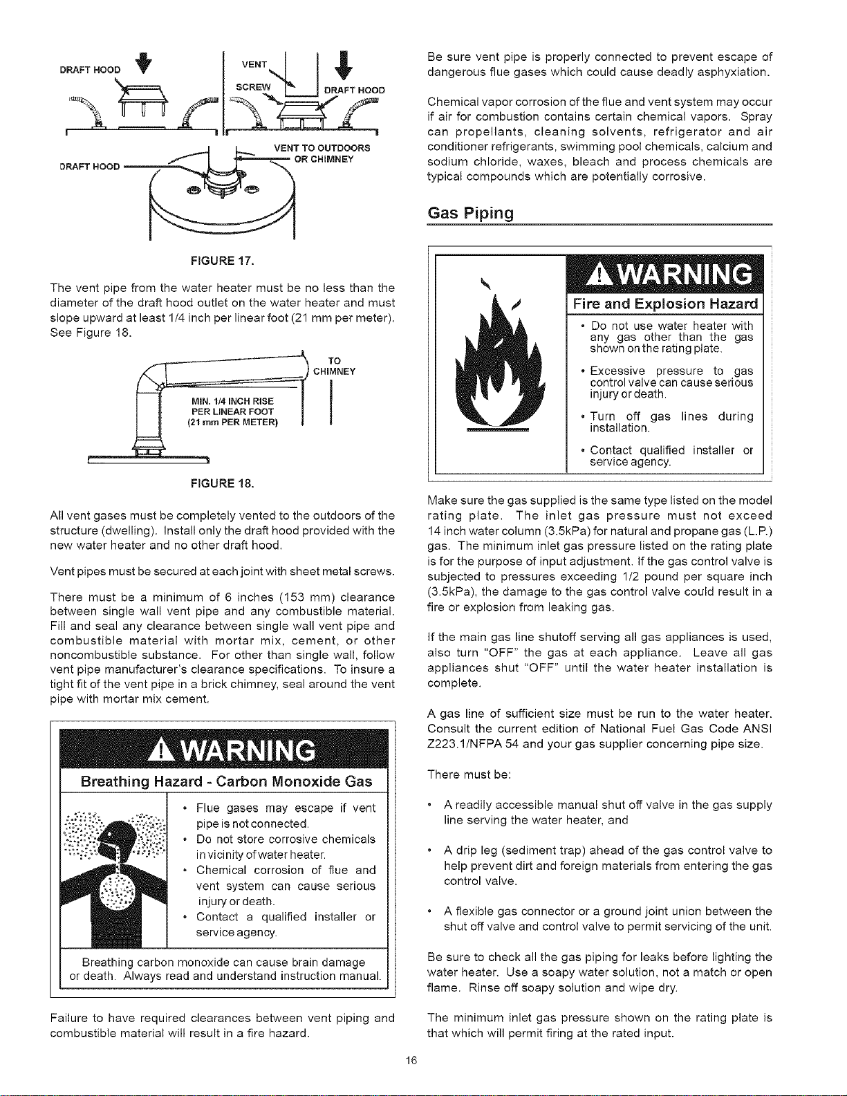
Place the vent pipe over the draft hood. With the vent pipe in
position, drill a small hole through both the vent pipe and
draft hood. Secure them together with a sheet metal screw.
See Figure 17.
Obstructed or deteriorated vent systems may present serious
health risk or asphyxiation.
15
O 'FTNOOD rE"T,,,,L $
f,l,
_._ VENT TO OUTDOORS
DRAFTHOOD ___R CHIMNEY
FIGURE 17.
The vent pipe from the water heater must be no less than the
diameter of the draft hood outlet on the water heater and must
slope upward at least 1/4 inch per linear foot (21 mm per meter).
See Figure 18.
CHIMNEY
FIGURE 18.
All vent gases must be completely vented to the outdoors of the
structure (dwelling). Install only the draft hood provided with the
new water heater and no other draft hood.
Vent pipes must be secured at each joint with sheet metal screws.
There must be a minimum of 6 inches (153 mm) clearance
between single wall vent pipe and any combustible material.
Fill and seal any clearance between single wall vent pipe and
combustible material with mortar mix, cement, or other
noncombustible substance. For other than single wall, follow
vent pipe manufacturer's clearance specifications. To insure a
tight fit of the vent pipe in a brick chimney, seal around the vent
pipe with mortar mix cement.
Breathing Hazard - Carbon Monoxide Gas
. Flue gases may escape if vent
pipe is not connected.
• Do not store corrosive chemicals
in vicinity of water heater.
• Chemical corrosion of flue and
vent system can cause serious
injury or death.
• Contact a qualified installer or
service agency.
Breathing carbon monoxide can cause brain damage
or death. Always read and understand instruction manual.
Be sure vent pipe is properly connected to prevent escape of
dangerous flue gases which could cause deadly asphyxiation.
Chemical vapor corrosion of the flue and vent system may occur
if air for combustion contains certain chemical vapors. Spray
can propellants, cleaning solvents, refrigerator and air
conditioner refrigerants, swimming pool chemicals, calcium and
sodium chloride, waxes, bleach and process chemicals are
typical compounds which are potentially corrosive.
Gas Piping
Fire and Explosion Hazard
• Do not use water heater with
any gas other than the gas
shown on the rating plate.
• Excessive pressure to gas
control valve can cause serious
injury or death.
• Turn off gas lines during
installation.
• Contact qualified installer or
service agency.
Make sure the gas supplied is the same type listed on the model
rating plate. The inlet gas pressure must not exceed
14 inch water column (3.5kPa) for natural and propane gas (L.R)
gas. The minimum inlet gas pressure listed on the rating plate
is for the purpose of input adjustment. If the gas control valve is
subjected to pressures exceeding 1/2 pound per square inch
(3.5kPa), the damage to the gas control valve could result in a
fire or explosion from leaking gas.
If the main gas line shutoff serving all gas appliances is used,
also turn "OFF" the gas at each appliance. Leave all gas
appliances shut "OFF" until the water heater installation is
complete.
A gas line of sufficient size must be run to the water heater.
Consult the current edition of National Fuel Gas Code ANSI
Z223.1/NFPA 54 and your gas supplier concerning pipe size.
There must be:
A readily accessible manual shut off valve in the gas supply
line serving the water heater, and
A drip leg (sediment trap) ahead of the gas control valve to
help prevent dirt and foreign materials from entering the gas
control valve.
A flexible gas connector or a ground joint union between the
shut off valve and control valve to permit servicing of the unit.
Be sure to check all the gas piping for leaks before lighting the
water heater. Use a soapy water solution, not a match or open
flame. Rinse off soapy solution and wipe dry.
Failure to have required clearances between vent piping and
combustible material will result in a fire hazard.
The minimum inlet gas pressure shown on the rating plate is
that which will permit firing at the rated input.
16
Breathing Hazard - Carbon Monoxide Gas
• High altitude orifice must be installed for
operation above 7,700 feet (2,347 m].
• Contact a qualified installer or service
agency.
Breathing carbon monoxide can cause brain damage or
death. Always read and understand instruction manual.
Sediment Traps
Fire and Explosion Hazard
• Contaminants in gas lines can
causefire or explosion.
• Clean all gas piping before
installation.
• Install drip leg in accordance with
NFPA 54.
Water heaters covered in this manual have been tested and
approved for installation at elevations up to 7,700 feet (2,347 m)
above sea level. For installation above 7,700 feet (2,347 m), the
water heater's Btu input should be reduced at the rate of 4
percent for each 1,0g0 feet (305 m) above sea level which
requires replacement of the burner orifice in accordance with
the National Fuel Gas CodeANSI Z223.1/NFPA54. Contact your
local gas supplier for further information.
Failure to replace the standard orifice with the proper high
altitude orifice when installed at elevations above 7,700 feet
(2,347m) could result in improper and inefficient operation of
the appliance, producing carbon monoxide gas in excess of
the safe limits. This could result in serious injury or death.
Contact your local gas supplier for any specific changes that
may be required in your area.
Fire and Explosion Hazard
o Use joint compound or tape
compatible with propane.
= Leak test before operating
heater.
-Disconnect gas piping and
shut-off valve before pressure
testing system.
Use pipe joint compound or teflon tape marked as being
resistant to the action of petroleum (Propane [L.R]) gases.
The appliance and its gas connection must be leak tested before
placing the appliance in operation.
The appliance and its individual shutoff valve shall be
disconnected from the gas supply piping system during any
pressure testing of that system at test pressures in excess of
1/2 pound per square inch (3.5kPa). It shall be isolated from
the gas supply piping system by closing its individual manual
shutoff valve during any pressure testing of the gas supply
piping system at test pressures equal to or less than 1/2 pound
per square inch (3.5kPa).
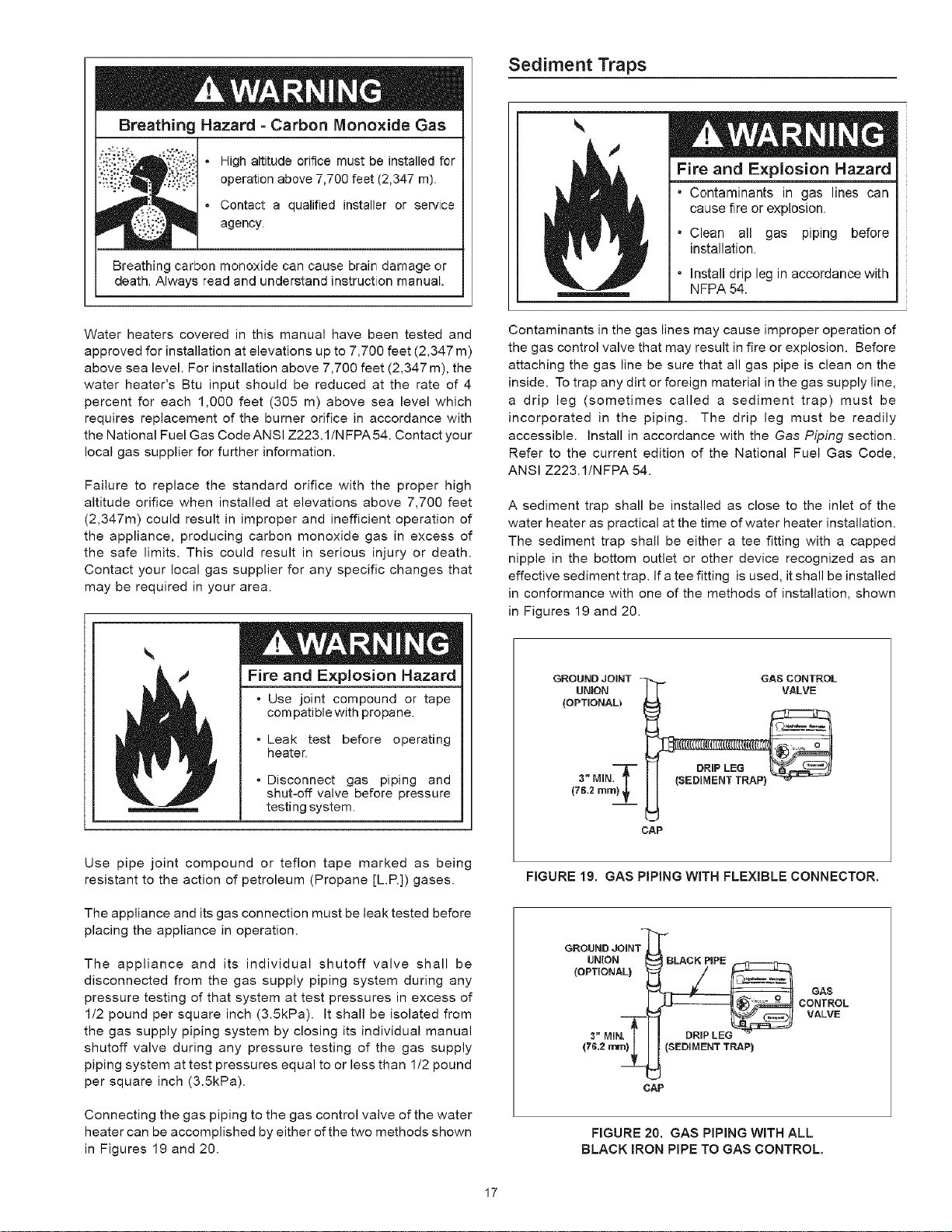
Connecting the gas piping to the gas control valve of the water
heater can be accomplished by either of the two methods shown
in Figures 19 and 20.
Contaminants in the gas lines may cause improper operation of
the gas control valve that may result in fire or explosion. Before
attaching the gas line be sure that all gas pipe is clean on the
inside. To trap any dirt or foreign material in the gas supply line,
a drip leg (sometimes called a sediment trap) must be
incorporated in the piping. The drip leg must be readily
accessible, install in accordance with the Gas Piping section.
Refer to the current edition of the National Fuel Gas Code,
ANSi Z223.1iNFPA 54.
A sediment trap shall be installed as close to the inlet of the
water heater as practical at the time of water heater installation.
The sediment trap shall be either a tee fitting with a capped
nipple in the bottom outlet or other device recognized as an
effective sediment trap. If a tee fitting is used, it shall be installed
in conformance with one of the methods of installation, shown
in Figures 19 and 20.
GROUND JOINT - GAS CONTROL
UNION
(OPTIONALI
3" MIN_"
(78.2 ram} ,_
CAP
FIGURE 19. GAS PIPING WITH FLEXIBLE CONNECTOR.
GROUND JOIN1 _'_B
LINION LACKPiPE
(OPT,ONAL} d ,/
_. n GAS
cOX;v.OL
CAP
FIGURE 20. GAS PiPiNG WITH ALL
BLACK IRON PmPETO GAS CONTROL,
17
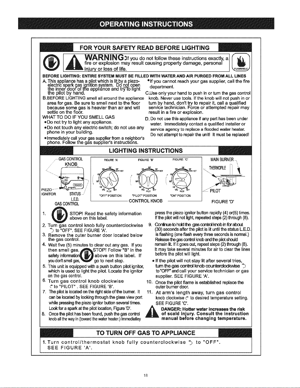
FOR YOUR SAFETY READ BEFORE LiGHTiNG
WARNING you do not follow these instructionsexactly, a
fire or explosion may result causing property damage, personal
njury or oss of re,
BEFORELiGHTiNG:ENTIRESYSTEMMUSTBEFILLEDWiTHWATERANDAiRPURGEDFROMALLLINES
A. T,his.a.ppJian,cehas.a .p.UotwhichisliLbya piezo- °if you cannotreachyourgas suppltar,call the fire
.e=ectncspark gas,lgmr_on,system. u9 notqpeq department.
me =nnerooor or me appliance one [ry to i=gm
the pilot by hand. C.Use onlyyour handto push inor turn thegas control
B.BEFORELIGHTINGsmellall around the appliance knob. Never usetools, ifthe knob willnot pushin or
area for gas. Be sure to smell next to the floor turn by hand, don't try to repair it,caJla quaJified
because some gas is heavier than air and wilm servicetechnician. Force or attempted repair may
settle on the floor, result in a Fireorexpfesion.
WHAT TO DO iF YOU SMELL GAS D. Donotusethis applianceifanypart hasbeenunder
,=Donot try to mightany appUance, water. Immediatelycontact a qualifiedinstalleror
ode not touch any electric switch; do not use any service agency to replace a floodedwater heater.
phone in your building. Donotattemptto repairtheunit! itmustbe replaced!
olmmediatelycallyour gassupplierfrom a neighbor's
phone. Follow the gas supplier's instructions.
7 GASCONTROL
KNOB
PIEZO
/
IGNITOR STATUS-'
LED.
GASCONTROL
LiGHTiNG iNSTRUCTiONS
FIGURE 'A'
f1_1,_. VER_ 1_3T
"OFF" POSITION
FIGURE 'B' FIGURE "C'
/ 11 vERYxO_ I VERYHOT
V_ pILOT _FF
"PILOT" POSITION "ON" POSITION
CONTROLKNOB
MAINBURNER•
THERMOPILE
PILOT
FIGURE 'D'
1. STOP! Read the safety information
above on this label.
2. Turn gas control knob fully counterclockwise
to "OFF". SEEFIGURE'A'.
3. Remove the outer burner door located below
the gas control.
4. Wait five (5) minutes to clear out anygas. If you
then smell gas, J_kSTOP! Follow "B" inthe
safetyintormatfen_J_f_ above on this label, if
youdon_smellgas,_ go to next step.
5. This unit isequippedwith a pushbutton pilotignitor,
which isused to light the pilot. Locate the ignitor
on thegascontrol.
6. Turn gas controm knob cmockwise
Gto "PILOT". SEE FIGURE 'B'.
7. ThepilotisIocafedontherightsideoftheburner,it
canbelocatedbymookingthroughtheglassviewpert
whimepressingthepiezoignitorbuttonseveraltimes.
Lookforasparkatthepilotlocation,Figure'D'.
8. Oncethepilothasbeenfound,pushthegascontrol
knoballthewayin(towardthewaterheater.)Immediatley
pressthepiezoignitorbuttonrapidly(4) or(5)times.
ffthe pilotwillnotlight,repeatedsteps(2)through(8).
g. _ue_holdthe gesconkdlmobinforabout
(30)secondsafterthepilotisJituntilthestatusL.E.D.
isflashing(oneflasheverythreesecondsisnormaL)
Releasethegascontrolknobandthepilotshould
remainlit.ifitgoesout,repeatsteps(2)through(8).
itmaytake severalminutesfor airto clesr thelines
beforethepilotwilllight.
• ifthe pilot will not stay litafter severaltries,
turnme gas oonirol knob oount_se
to"OFF"andcall your service technician or gas
supplier. SEE FIGURE 'A'.
10. Oncethe pilotflameisestablishedreplacethe
outerburnerdoor.
11. At arm's length away, turn gas control
knob clockwiseG to desiredtemperaturesetting.
SEE FIGURE'C'.
_ DANGER:Hotterwaterincreasesthe risk
of scald injury. Consult the instruction
rnanual before changing temperature,
TO TURN OFF GAS TO APPLIANCE
1. Turn control/thermostat knob fully counterclockwise _ to "OFF".
SEE FIGURE 'A'.
18
Temperature Regulation
Due to the nature of the typical gas water heater, the water
temperature in certain situations may vary up to 30F ° (16.7 C °)
higher or lower at the point of use such as, bathtubs, showers,
sink, etc.
Any water heater's intended purpose is to heat water. Hot
water is needed for cleansing, cleaning, and sanitizing (bodies,
dishes, clothing). Untempered hot water can present a scald
hazard. Depending on the time element, and the people
involved (adults, children, elderly, infirm, etc.) scalding may
occur at different temperatures.
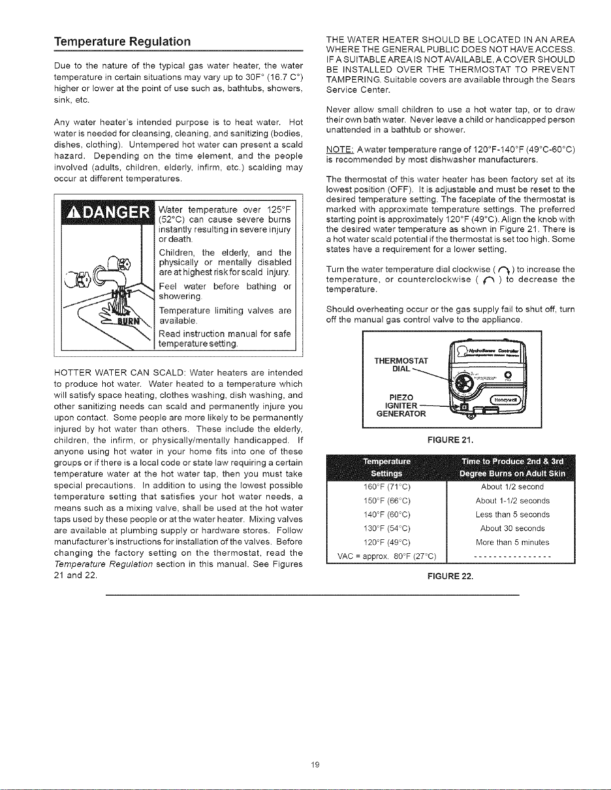
Water temperature over 125°F
(52°0) can cause severe burns
instantly resulting in severe injury
or death.
Children, the elderly, and the
physically or mentally disabled
are at highest dskforscaid injury.
Feel water before bathing or
showering.
Temperature limiting valves are
available.
Read instruction manual for safe
temperature setting.
HOTTER WATER CAN SCALD: Water heaters are intended
to produce hot water. Water heated to a temperature which
will satisfy space heating, clothes washing, dish washing, and
other sanitizing needs can scald and permanently injure you
upon contact. Some people are more likely to be permanently
injured by hot water than others. These include the elderly,
children, the infirm, or physically/mentally handicapped. If
anyone using hot water in your home fits into one of these
groups or if there is a local code or state law requiring a certain
temperature water at the hot water tap, then you must take
special precautions. In addition to using the lowest possible
temperature setting that satisfies your hot water needs, a
means such as a mixing valve, shall be used at the hot water
taps used by these people or at the water heater. Mixing valves
are available at plumbing supply or hardware stores. Follow
manufacturer's instructions for installation of the valves. Before
changing the factory setting on the thermostat, read the
Temperature Regulation section in this manual. See Figures
21 and 22.
THE WATER HEATER SHOULD BE LOCATED IN AN AREA
WHERE THE GENERAL PUBLIC DOES NOT HAVE ACCESS.
IF A SUITABLE AREA IS NOT AVAILABLE, A COVER SHOULD
BE INSTALLED OVER THE THERMOSTAT TO PREVENT
TAMPERING. Suitable covers are available through the Sears
Service Center.
Never allow small children to use a hot water tap, or to draw
their own bath water. Never leave a child or handicapped person
unattended in a bathtub or shower.
NOTE: Awater temperature range of 120°F-140°F (49°C-60°C)
is recommended by most dishwasher manufacturers.
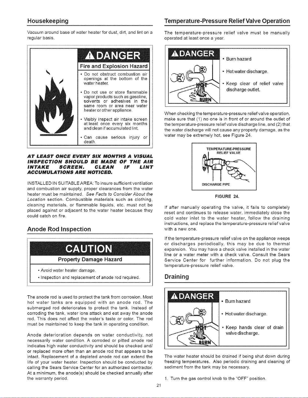
The thermostat of this water heater has been factory set at its
lowest position (OFF). It is adjustable and must be reset to the
desired temperature setting. The faceplate of the thermostat is
marked with approximate temperature settings. The preferred
starting point is approximately 120°F (49°C). Align the knob with
the desired water temperature as shown in Figure 21. There is
a hot water scald potential if the thermostat is set too high. Some
states have a requirement for a lower setting.
Turn the water temperature dial clockwise ( t_ ) to increase the
temperature, or counterclockwise ( _ ) to decrease the
temperature.
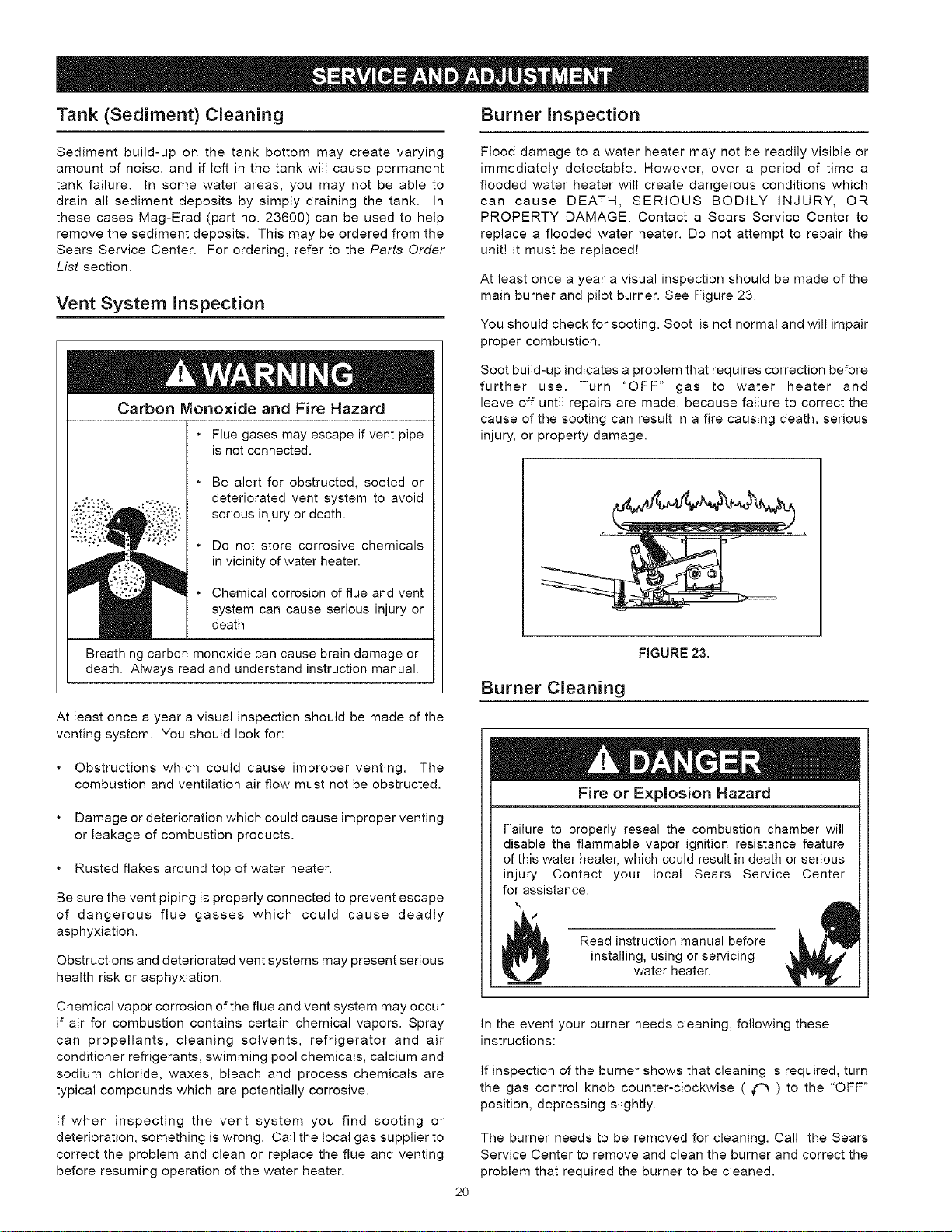
Should overheating occur or the gas supply fail to shut off, turn
off the manual gas control valve to the appliance.
THERMOSTAT
PIEZO I_Y_ / _l(
iGNiTER--_---((_ __J_
GENERATOR
FIGURE 21.
I60°F (71°C) About 1/2 second
I50°F (66°C)
I40°F (60°C)
I30°F (54°C)
I20°F (49°C)
VAC = approx. 80°F (27°C)
About 1-1/2 seconds
Less than 5 seconds
About 30 seconds
More than 5 minutes
FIGURE 22.
19
Tank (Sediment) Cleaning Burner Inspection
Sediment build-up on the tank bottom may create varying
amount of noise, and if left in the tank will cause permanent
tank failure. In some water areas, you may not be able to
drain all sediment deposits by simply draining the tank. In
these cases Mag-Erad (part no. 23600) can be used to help
remove the sediment deposits. This may be ordered from the
Sears Service Center. For ordering, refer to the Parts Order
List section.
Vent System Inspection
Carbon Monoxide and Fire Hazard
• Flue gases may escape if vent pipe
is not connected.
|
. Be alert for obstructed, sooted or
deteriorated vent system to avoid
serious injury or death.
. Do not store corrosive chemicals
in vicinity of water heater.
Chemical corrosion of flue and vent
system can cause serious injury or
death
Breathing carbon monoxide can cause brain damage or
death. Always read and understand instruction manual.
At least once a year a visual inspection should be made of the
venting system. You should look for:
Obstructions which could cause improper venting. The
combustion and ventilation air flow must not be obstructed.
Damage or deterioration which could cause improper venting
or leakage of combustion products.
Rusted flakes around top of water heater.
Be sure the vent piping is properly connected to prevent escape
of dangerous flue gasses which could cause deadly
asphyxiation.
Obstructions and deteriorated vent systems may present serious
health risk or asphyxiation.
Chemical vapor corrosion of the flue and vent system may occur
if air for combustion contains certain chemical vapors. Spray
can propellants, cleaning solvents, refrigerator and air
conditioner refrigerants, swimming pool chemicals, calcium and
sodium chloride, waxes, bleach and process chemicals are
typical compounds which are potentially corrosive.
If when inspecting the vent system you find sooting or
deterioration, something is wrong. Call the local gas supplier to
correct the problem and clean or replace the flue and venting
before resuming operation of the water heater.
Flood damage to a water heater may not be readily visible or
immediately detectable. However, over a period of time a
flooded water heater will create dangerous conditions which
can cause DEATH, SERIOUS BODILY INJURY, OR
PROPERTY DAMAGE. Contact a Sears Service Center to
replace a flooded water heater. Do not attempt to repair the
unit! It must be replaced!
At least once a year a visual inspection should be made of the
main burner and pilot burner. See Figure 23.
You should check for sooting. Soot is not normal and will impair
proper combustion.
Soot build-up indicates a problem that requires correction before
further use. Turn "OFF" gas to water heater and
leave off until repairs are made, because failure to correct the
cause of the sooting can result in a fire causing death, serious
injury, or property damage.
FIGURE 23,
Burner Cleaning
Fire or Explosion Hazard
Failure to properly reseal the combustion chamber will
disable the flammable vapor ignition resistance feature
of this water heater, which could result in death or serious
injury. Contact your local Sears Service Center
for assistance.
Read instruction manual before
installing, using or servlcmg
water heater.
2O
In the event your burner needs cleaning, following these
instructions:
If inspection of the burner shows that cleaning is required, turn
the gas control knob counter-clockwise ( _ ) to the "OFF"
position, depressing slightly.
The burner needs to be removed for cleaning. Call the Sears
Service Center to remove and clean the burner and correct the
problem that required the burner to be cleaned.
Housekeeping
Vacuum around base of water heater for dust, dirt, and lint on a
regular basis.
Fire and Explosion Hazard
• Do not obstruct combustion air
openings at the bottom of the
water heater.
Do not use or store flammable
vapor products such as gasoline,
solvents or adhesives in the
same room or area near water
heater or other appliance.
Visibly inspect air intake screen
at least once every six months
and clean if accumulated lint.
• Can cause serious injury or
death.
INSTALLED IN SUITABLE AREA: To insure sufficient ventilation
and combustion air supply, proper clearances from the water
heater must be maintained. See Facts to Consider About the
Location section. Combustible materials such as clothing,
cleaning materials, or flammable liquids, etc. must not be
placed against or adjacent to the water heater because they
could catch on fire.
Anode Rod Inspection
Property Damage Hazard
• Avoid water heater damage.
-Inspection and replacement of anode rod required.
Temperature=Pressure Relief Valve Operation
The temperature-pressure relief valve must be manually
operated at least once a year.
• Burn hazard
. Hot water discharge.
• Keep clear of relief valve
discharge outlet.
When checking the temperature-pressure relief valve operation,
make sure that (1) no one is in front of or around the outlet of
the temperature-pressure relief valve discharge line, and (2) that
the water discharge will not cause any property damage, as the
water may be extremely hot, see Figure 24.
TEMPERATURE-PRESSURE
DISCHARGEPiPE
FIGURE 24.
If after manually operating the valve, it fails to completely
reset and continues to release water, immediately close the
cold water inlet to the water heater, follow the draining
instructions, and replace the temperature-pressure relief valve
with a new one.
If the temperature-pressure relief valve on the appliance weeps
or discharges periodically, this may be due to thermal
expansion. You may have a check valve installed in the water
line or a water meter with a check valve. Consult the Sears
Service Center for further information. Do not plug the
temperature-pressure relief valve.
Draining
The anode rod is used to protect the tank from corrosion. Most
hot water tanks are equipped with an anode rod. The
submerged rod deteriorates to protect the tank. Instead of
corroding the tank, water ions attack and eat away the anode
rod. This does not affect the water's taste or color. The rod
must be maintained to keep the tank in operating condition.
Anode deterioration depends on water conductivity, not
necessarily water condition. A corroded or pitted anode rod
indicates high water conductivity and should be checked and/
or replaced more often than an anode rod that appears to be
intact. Replacement of a depleted anode rod can extend the
life of your water heater. Inspection should be conducted by
calling the Sears Service Center for an authorized contractor.
At a minimum, the anode(s) should be checked annually after
the warranty period.
,, Burn hazard
• Hotwater discharge.
• Keep hands clear of drain
valve discharge.
2I
The water heater should be drained if being shut down during
freezing temperatures. Also periodic draining and cleaning of
sediment from the tank may be necessary.
1. Turn the gas control knob to the "OFF" position.

2.CLOSEthecoldwaterinletvalvetothewaterheater.
3.OPENanearbyhotwaterfaucetandleaveopentoallowfor
draining.
4.Connectahosetothedrainvalveandterminatetoan
adequatedrain.
5.OPENthewaterheaterdrainvalvetoallowfortankdraining.
NOTE:Ifthewaterheateris going to be shut down and
drained for an extended period, the drain valve should
be left open with hose connected allowing water to
terminate to an adequate drain.
6. Close the drain valve.
7. Follow instructions in the Filling The Water heater section.
8. Follow the lighting instructions in the Lighting section to restart
the water heater.
Drain Valve Washer Replacement
(See Figure 25)
1. Turn "OFF" gas supply to water heater.
2. Follow "Draining" instructions.
3. Turning counter clockwise ( _ ), remove the hex cap below
the screw handle.
4. Remove the washer and put the new one in place.
5. Screw the handle and cap assembly back into the drain
valve and retighten using a wrench. DO NOT OVER
TIGHTEN.
6. Follow instructions in the Filling The Water Heater section.
7. Check for leaks.
8. Followthe lighting instructions in the Lighting section to restart
the water heater.
_HANDLE AND
CAP ASSEMBLY
WASHER
FIGURE 25,
Service
Before calling for repair service, read the Start Up Conditions
and Operational Conditions found in the Troubleshooting Guide
of this manual.
If a condition persists or you are uncertain about the operation
of the water heater, let the Sears Service Center check it out.
Contact Sears Service Center at:
1-800-4-MY-HOME _ (1-800-469-4663).
22
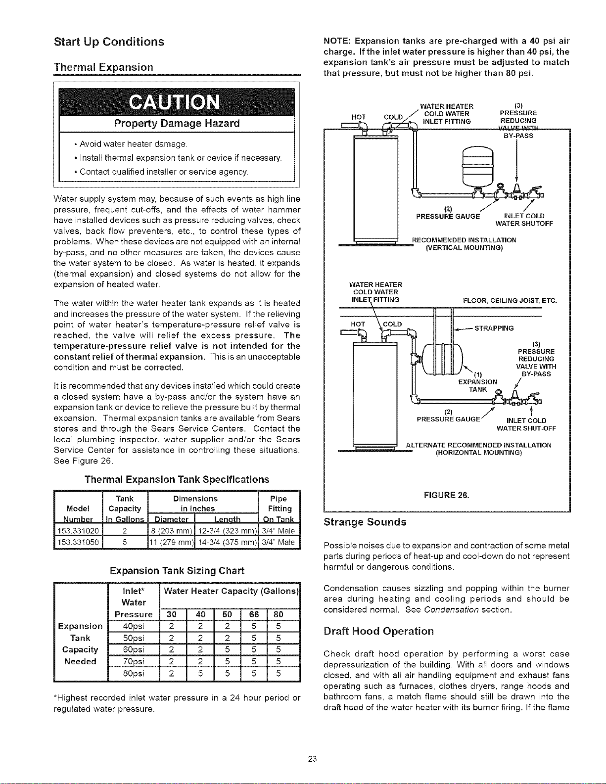
Start Up Conditions
Thermal Expansion
Property Damage Hazard
- Avoid water heater damage,
• Install thermal expansion tank or device if necessary.
. Contact qualified installer or service agency.
Water supply system may, because of such events as high line
pressure, frequent cut-offs, and the effects of water hammer
have installed devices such as pressure reducing valves, check
valves, back flow preventers, etc., to control these types of
problems. When these devices are not equipped with an internal
by-pass, and no other measures are taken, the devices cause
the water system to be closed. As water is heated, it expands
(thermal expansion) and closed systems do not allow for the
expansion of heated water.
The water within the water heater tank expands as it is heated
and increases the pressure of the water system. If the relieving
point of water heater's temperature-pressure relief valve is
reached, the valve will relief the excess pressure. The
temperature-pressure relief valve is not intended for the
constant relief of thermal expansion. This is an unacceptable
condition and must be corrected.
It is recommended that any devices installed which could create
a closed system have a by-pass and/or the system have an
expansion tank or device to relieve the pressure built by thermal
expansion. Thermal expansion tanks are available from Sears
stores and through the Sears Service Centers. Contact the
local plumbing inspector, water supplier and/or the Sears
Service Center for assistance in controlling these situations.
See Figure 26.
Thermal Expansion Tank Specifications
Mode!
Number
153.331020
153.331050
Tank
Capacity
in Gallons
2
5
Dimensions Pipe
in inches Fitting
Diameter Lenoth On Tank
18 {203 ram) I2-3/4 {323 ram) 3/4" Mate
11(279 ram) I4-3/4 (375 ram) 3/4" Mate
Expansion Tank Sizing Chart
Water Heater Capacity (Gallons)
inlet*
Water
Pressure
40psi
50psi
60psi
70psi
80psi
30 40 50 66 80
Expansion 2 2 2 5 5
Tank 2 2 2 5 5
Capacity 2 2 5 5 5
Needed 2 2 5 5 5
2 5 5 5 5
*Highest recorded inlet water pressure in a 24 hour period or
regulated water pressure.
NOTE: Expansion tanks are pre=charged with a 40 psi air
charge. If the inlet water pressure is higher than 40 psi, the
expansion tank's air pressure must be adjusted to match
that pressure, but must not be higher than 80 psi.
WATERHEATER (3)
H_T r'nRr_ _" COLDWATER PRESSURE
....... _[_.._,_ iNLET FITTING *'_REDUCING
! BY-PASS
PRESSURE GAUGE INLET COLD
WATERSHUTOFF
RECOMMENDEDiNSTALLATiON
-- -- -- (VERTICALMOUNTING)
WATER HEATER
COLD WATER
iNLET FiTTiNG FLOOR, CEILING JOIST, ETC.
)k II Jl
r__ HOT COL C .,_---- STRAPPING
J f
PRESSURE GAUGE iNLET COLD
WATER SHUT-OFF
ALTERNATE RECOMMENDEDINSTALLATION
(HORIZONTALMOUNTING)
FIGURE 26.
Strange Sounds
Possible noises due to expansion and contraction of some metal
parts during periods of heat-up and cool-down do not represent
harmful or dangerous conditions.
Condensation causes sizzling and popping within the burner
area during heating and cooling periods and should be
considered normal. See Condensation section.
Draft Hood Operation
Check draft hood operation by performing a worst case
depressurization of the building. With all doors and windows
closed, and with all air handling equipment and exhaust fans
operating such as furnaces, clothes dryers, range hoods and
bathroom fans, a match flame should still be drawn into the
draft hood of the water heater with its burner firing. If the flame
23
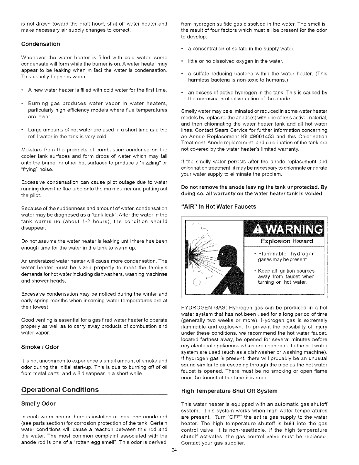
isnotdrawntowardthedrafthood,shutoffwaterheaterand
makenecessaryairsupplychangestocorrect.
Condensation
Whenever the water heater is filled with cold water, some
condensate will form while the burner is on. A water heater may
appear to be leaking when in fact the water is condensation.
This usually happens when:
• A new water heater is filled with cold water for the first time.
Burning gas produces water vapor In water heaters,
particularly high efficiency models where flue temperatures
are lower.
Large amounts of hot water are used in a short time and the
refill water in the tank is very cold.
Moisture from the products of combustion condense on the
cooler tank surfaces and form drops of water which may fall
onto the burner or other hot surfaces to produce a "sizzling" or
"frying" noise.
Excessive condensation can cause pilot outage due to water
running down the flue tube onto the main burner and putting out
the pilot.
Because of the suddenness and amount of water, condensation
water may be diagnosed as a "tank leak". After the water in the
tank warms up (about 1-2 hours), the condition should
disappear.
Do not assume the water heater is leaking until there has been
enough time for the water in the tank to warm up.
An undersized water heater will cause more condensation. The
water heater must be sized properly to meet the family's
demands for hot water including dishwashers, washing machines
and shower heads.
Excessive condensation may be noticed during the winter and
early spring months when incoming water temperatures are at
their lowest.
Good venting is essential for a gas fired water heater to operate
properly as well as to carry away products of combustion and
water vapor.
Smoke / Odor
It is not uncommon to experience a small amount of smoke and
odor during the initial start-up. This is due to burning off of oil
from metal parts, and will disappear in a short while.
Operational Conditions
Smelly Odor
In each water heater there is installed at least one anode rod
(see parts section) for corrosion protection of the tank. Certain
water conditions will cause a reaction between this rod and
the water. The most common complaint associated with the
anode rod is one of a "rotten egg smell". This odor is derived
from hydrogen sulfide gas dissolved in the water. The smell is
the result of four factors which must all be present for the odor
to develop:
a concentration of sulfate in the supply water.
little or no dissolved oxygen in the water.
a sulfate reducing bacteria within the water heater. (This
harmless bacteria is non-toxic to humans.)
an excess of active hydrogen in the tank. This is caused by
the corrosion protective action of the anode.
Smelly water may be eliminated or reduced in some water heater
models by replacing the anode(s) with one of less active material,
and then chlorinating the water heater tank and all hot water
lines. Contact Sears Service for further information concerning
an Anode Replacement Kit #9001453 and this Chlorination
Treatment. Anode replacement and chlorination of the tank are
not covered by the water heater's limited warranty.
If the smelly water persists after the anode replacement and
chlorination treatment, it may be necessary to chlorinate or aerate
your water supply to eliminate the problem.
Do not remove the anode leaving the tank unprotected. By
doing so, all warranty on the water heater tank is voided,
"AIR" in Hot Water Faucets
}.--\
Explosion Hazard
• Flammable hydrogen
gases may be present.
* Keep all ignition sources
away from faucet when
turning on hot water.
24
HYDROGEN GAS: Hydrogen gas can be produced in a hot
water system that has not been used for a long period of time
(generally two weeks or more). Hydrogen gas is extremely
flammable and explosive. To prevent the possibility of injury
under these conditions, we recommend the hot water faucet,
located farthest away, be opened for several minutes before
any electrical appliances which are connected to the hot water
system are used (such as a dishwasher or washing machine).
If hydrogen gas is present, there will probably be an unusual
sound similar to air escaping through the pipe as the hot water
faucet is opened. There must be no smoking or open flame
near the faucet at the time it is open.
High Temperature Shut Off System
This water heater is equipped with an automatic gas shutoff
system. This system works when high water temperatures
are present. Turn "OFF" the entire gas supply to the water
heater. The high temperature shutoff is built into the gas
control valve. It is non-resettable. If the high temperature
shutoff activates, the gas control valve must be replaced.
Contact your gas supplier.

Operational Conditions (Continued)
Leakage Checkpoints
FIGURE 27.
Read and understand instruction
manual and safety messages
before installing, operating or
servicing thiswater heater.
Failure to follow instructions and
safety messages could result in
death or serious injury.
Instruction Manual must remain
with water heater.
Read this manual first. Then before checking the water heater
make sure the gas supply has been turned "OFF", and never
turn the gas "ON" before the tank is completely full of water.
Never use this water heater unless it is completely filled with
water. To prevent damage to the tank, the tank must be filled
with water. Water must flow from the hot water faucet before
turning "ON" gas to the water heater, see Figure 27.
A. Water at the draft hood is water vapor which has condensed
out of the combustion products. This is caused by a problem
in the vent. Contact the gas utility.
B. *Condensation may be seen on pipes in humid weather or
pipe connections may be leaking.
C. *The anode rod fitting may be leaking.
D. Small amounts of water from temperature-pressure relief
valve may be due to thermal expansion or high water pressure
in your area.
E. *The temperature-pressure relief valve may be leaking at the
tank fitting.
F. Water from a drain valve may be due to the valve being slightly
opened.
G. *The drain valve may be leaking at the tank fitting.
a.
Combustion products contain water vapor which can
condense on the cooler surfaces of the tank. Droplets form
and drip onto the burner or run on the floor. This is common
at the time of start-up after installation and when incoming
water is cold.
Water in the water heater bottom or on the floor may be from
condensation, loose connections, or the relief valve.
DO NOT replace the water heater until a full inspection of all
possible water sources is made and necessary corrective
steps taken.
Leakage from other appliances, water lines, or ground seepage
should also be checked.
To check where threaded portion enters tank, insert cotton
swab between jacket opening and fitting. If cotton is wet,
follow "Draining" instructions in the Periodic Maintenance
section and then remove fitting. Put pipe dope or teflon
tape on the threads and replace. Then follow Filling the
Water Heater instructions in the Installing the New Water
Heater section.
25

A.Toolsrequired:
1.T15TorxScrewdriver
5. Removethetorxscrewlocatedbesidethepilottubeonthe
lowerfrontofthegasvalveassemblywithaT15torx
screwdriver.
2. 3/16"slottedscrewdriver.
3. Open-endwrenches7/16",and3/4".
Fortheseinstructions, please see Figure 28.
B. Removing Electronic Control Module:
1. Turn the gas control/temperature knob to the "OFF" position.
2. Turn offthe gas at the manual shut-offvalve on the gas supply
line.
3. Disconnect the wire connectors from the piezo igniter, tank
sensors, and thermopile mounted on the lower front of the
gas control valve assembly.
6. Depress the two plastic locking tabs on lower front surface of
gas valve with a 3/16" slotted screwdriver.
7. Grasp the sides of the gas valve and pull outward to remove.
D. Removing Gas Valve Backplate:
1. Follow steps 1 to 7 in C above to remove the gas valve assembly.
2. Pull forward or break off the two plastic locking tabs using a
3/16" slotted screwdriver.
3. Grasp the sides of the back-plate and slide upward to remove
it from the gas valve nipple.
E: installing Gas Valve Assembly:
4. Remove the torx screw located beside the pilot tube on the
lower front of the electronic control module with a T15 torx
screwdriver.
1. Install the new gas valve (with back-plate) on the tank nipple
by sliding the assembly downward until the locking tabs are
fully engaged.
5. Depress the two plastic locking tabs on the top surface of
the electronic control module with a 3/16" slotted
screwdriver.
6. Grasp the sides of the electronic control module and pull
outward to remove.
C. Removing Gas Valve Assembly:
1. Follow steps 1 to 6 in B above to remove the electronic control
module.
2. Disconnect the inlet gas supply to the gas valve.
3. Loosen the flare nut that connects the pilot tube to the bottom
of the gas control valve assembly with a 7/16" open-end
wrench. Pull down on the pilot tube to separate the tube from
the gas valve.
4. Loosen the flange nut that connects the burner tube to bottom
of gas control valve with a 3/4" open-end wrench. Pull down
on the burner tube to separate the tube from the gas valve.
F:
1.
4.
Insure the gas valve is securely locked before proceeding to
next step.
Reconnect the burner tube, pilot tube, and inlet gas supply
line to the gas valve. Tighten securely and check for gas leaks.
installing Electronic Control Module:
Align the two plastic locking tabs on the top surface of the
electronic control module with the openings of the gas valve
back-plate. Press on the front of the control module until it
locks into position.
Reinstall the torx screw on the lower front of the electronic
control module (beside pilot tube) with a T15 torx screwdriver.
Tighten securely.
Reconnect the wire connectors from the piezo igniter, tank
sensors, and thermopile to the electronic control module.
Light the heater following the lighting and operating
instructions on the front surface of the heater.
26
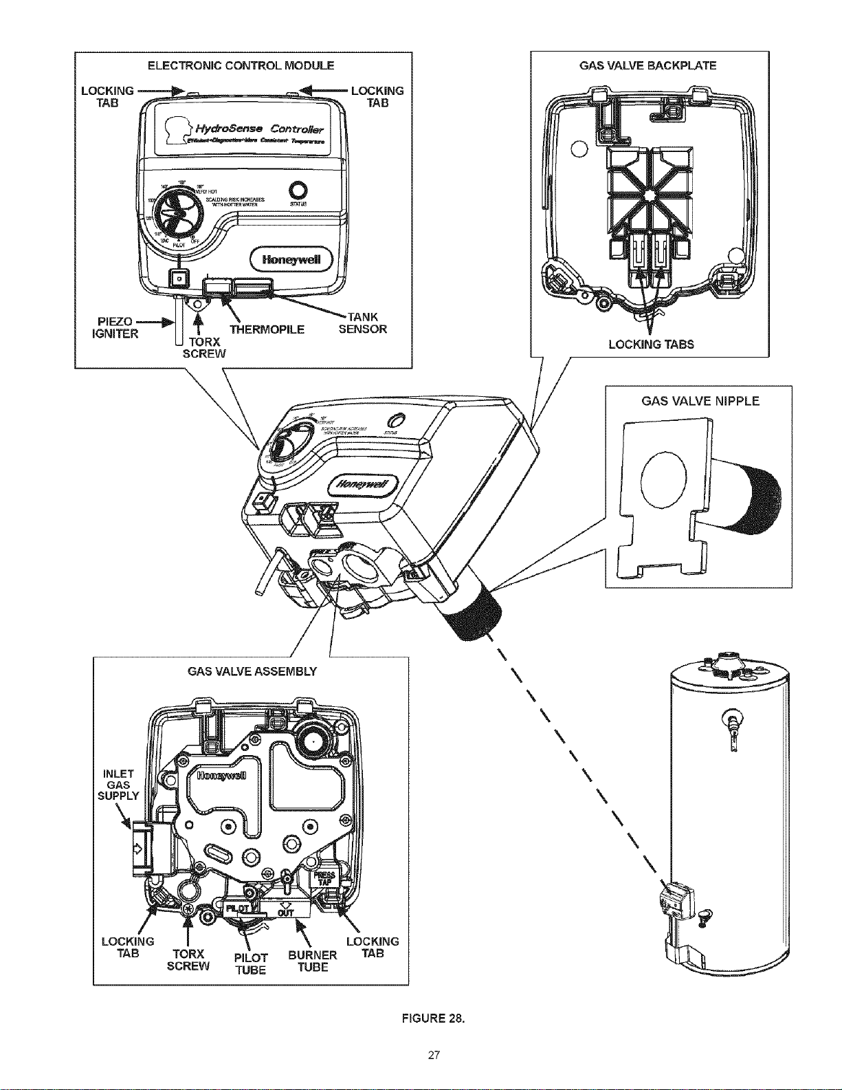
LOCKING
TAB
GAS
SUPPLY
ELECTRONIC CONTROL MODULE
THERMOPILE
TORX
SCREW
LOCKING
TAB
_TANK
SENSOR
GAS VALVE BACKPLATE
LOCKING TABS
GAS VALVE NIPPLE
LOCKmNG
TAB
GAS VALVE ASSEMBLY
TORX PILOT BURNER
SCREW TUBE TUBE
LOCKING
TAB
\
\
\
\
\
\
\
\
\
\
\
FIGURE 28.
27
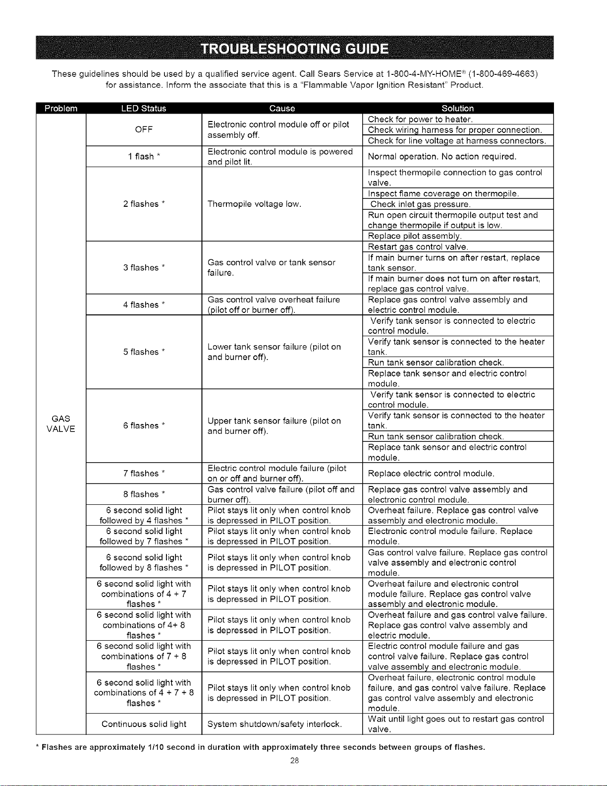
Theseguidelinesshouldbeusedbyaqualifiedserviceagent.CallSearsServiceat1-800-4-MY-HOME_(1-800-469-4663)
forassistance.Informtheassociatethatthisisa"FlammableVaporIgnitionResistant"Product.
IIIIIiI .I l_lll I II ilt,."lt,;.ilil. I-;- lll-:.l.
OFF
GAS
VALVE
1 flash *
2flashes *
3flashes *
4flashes *
5flashes *
6flashes *
7flashes *
8flashes *
6 second solid light
followed by 4 flashes *
6 second solid light
followed by 7 flashes *
6 second solid light
followed by 8 flashes *
6 second solid light with
combinations of 4 + 7
flashes *
6 second solid light with
combinations of 4+ 8
flashes *
6 second solid light with
combinations of 7 + 8
flashes *
gI_I,.,UUIIII., I.,UIILIUI I[IULILII_ l.lll UI t.)IIUL
assembly off.
Electronic control module is powered
and pilot lit.
Thermopile voltage low.
Gas control valve or tank sensor
failure.
Gas control valve overheat failure
(pilot off or burner off).
Lower tank sensor failure (pilot on
and burner off).
Upper tank sensor failure (pilot on
and burner off).
Electric control module failure (pilot
on or off and burner off).
Gas control valve failure (pilot off and
burner off).
Pilot stays lit only when control knob
is depressed in PILOT position.
Pilot stays lit only when control knob
is depressed in PILOT position.
Pilot stays lit only when control knob
is depressed in PILOT position.
Pilot stays lit only when control knob
is depressed in PILOT position.
Pilot stays lit only when control knob
is depressed in PILOT position.
Pilot stays lit only when control knob
is depressed in PILOT position.
6 second solid light with
combinations of 4 + 7 + 8 Pilot stays lit only when control knob
flashes * is depressed in PILOT position.
Continuous solid light System shutdown/safety interlock.
__11111i[o]
Check for power to heater.
Check wiring harness for proper connection.
Check for line voltage at harness connectors.
Normal operation. No action required.
inspect thermopile connection to gas control
valve.
inspect flame coverage on thermopile.
Check inlet gas pressure.
Run open circuit thermopile output test and
change thermopile if output is low.
Replace pilot assembly.
Restart gas control valve.
If main burner turns on after restart, replace
tank sensor.
If main burner does not turn on after restart,
replace gas control valve.
Replace gas control valve assembly and
electric control module.
Verify tank sensor is connected to electric
control module.
Verify tank sensor is connected to the heater
tank.
Run tank sensor calibration check.
Replace tank sensor and electric control
module.
Verify tank sensor is connected to electric
control module.
Verify tank sensor is connected to the heater
tank.
Run tank sensor calibration check.
Replace tank sensor and electric control
module.
Replace electric control module.
Replace gas control valve assembly and
electronic control module.
Overheat failure. Replace gas control valve
assembly and electronic module.
Electronic control module failure. Replace
module.
Gas control valve failure. Replace gas control
valve assembly and electronic control
module.
Overheat failure and electronic control
module failure. Replace gas control valve
assembly and electronic module.
Overheat failure and gas control valve failure.
Replace gas control valve assembly and
electric module.
Electric control module failure and gas
control valve failure. Replace gas control
valve assembly and electronic module.
Overheat failure, electronic control module
failure, and gas control valve failure. Replace
gas control valve assembly and electronic
module.
Wait until light goes out to restart gas control
valve.
* Flashes are approximately 1/10 second in duration with approximately three seconds between groups of flashes.
28

Theseguidelinesshouldbeusedbyaqualifiedserviceagent.CallSearsServiceat1-800-4-MY-HOME_(1-800-469-4663)
forassistance.Informtheassociatethatthisisa"FlammableVaporIgnitionResistant"Product.
/|'i'i|'tll
WATERLEAKS
LEAKINGT&PVALVE
SMELLYODORS
PILOTWILLNOTLIGHT
BURNERWILLNOTSTAYLIT
PILOTOUTAGE
NOTENOUGHHOTWATER
WATERTOOHOT
WATERHEATERSOUNDS
SIZZLING- RUMBLING
SOOTING
VENTGASODORS
-1_1,1-1
improperly sealed, hot or cold supply
connection, relief valve, drain valve, or
thermostat threads.
Leakage from other appliances or water
lines.
Condensation of flue products.
Thermal expansion in closed water system.
Improperly seated valve.
High sulfate or mineral content in water
supply.
Bacteria in water supply.
Gas knob dial not positioned correctly.
Main gas supply off.
Igniter tip more than 1/8" from pilot hood.
Thermopile malfunction.
Thermopile TCO malfunction.
Melted insulation on ignitor wire or shorting
of ignitor wire.
High ambient room temperature.
Wire disconnected from piezo igniter.
Broken electrode or electrical wire.
Piezo Igniter generator fails to operate or
malfunctions.
Thermopile TCO malfunction.
High ambient room temperature.
Dirty or clogged intake Screen.
Flame arrestor openings blocked.
Defective Gas Control.
Dirty pilot burner.
Dirty or clogged Air Intake Screen.
Thermopile malfunction.
Thermopile TCO malfunction.
Defective Gas Control.
Heater not lit or thermostat not on.
Thermostat set too low.
Heater undersized.
Low gas pressure.
incoming water is unusually cold.
Leaking hot water pipes or fixtures.
High temperature limit switch activated.
Thermostat set too high.
Condensation dripping on burner.
Sediment or calcium in bottom or heater
tank.
improper combustion.
Lack of supply air.
improperly installed vent piping.
Downdraft.
Poor Combustion.
-|'tl'lll'il
Tighten threaded connections.
Inspect other appliances near water
heater.
Refer to CONDENSATION.
Install thermal expansion tank (DO NOT
plug T&P valve).
Check relief valve for proper operation
(DO NOT plug T&P valve).
Drain and flush heater thoroughly, then
refill.
Chlorinate or aerate water supply.
Refer to LIGHTING INSTRUCTIONS.
Turn on main gas shutoff valve.
Adjust ignitor tip.
Replace pilot assembly.
Replace pilot assembly.
Contact Sears Service to determine
cause.
Contact Sears Service to determine
cause.
Reconnect wire connector to piezo igniter.
Replace pilot assembly.
Replace electronic control module.
Replace pilot assembly.
Contact Sears Service to determine
cause.
Clean and reinstall Air Intake Screen.
Contact Sears Service to determine
cause.
Replace Gas Control.
Clean pilot assembly.
Clean and reinstall Air Intake Screen.
Replace pilot assembly.
Replace pilot assembly.
Replace Gas Control.
Refer to LIGHTING INSTRUCTIONS.
Refer to TEMPERATURE REGULATION.
Reduce hot water use.
Contact your gas supplier.
Allow more time for your heater to re-heat.
Have plumber check and repair leaks.
Contact Sears Service to determine
cause.
Refer to TEMPERATURE REGULATION.
Refer to CONDENSATION.
Clean sediment from tank. Refer to
DRAINING instructions in Maintenance
section of manual.
No adjustment available. Contact Sears
Service to determine cause.
Contact Sears Service to determine
cause.
29
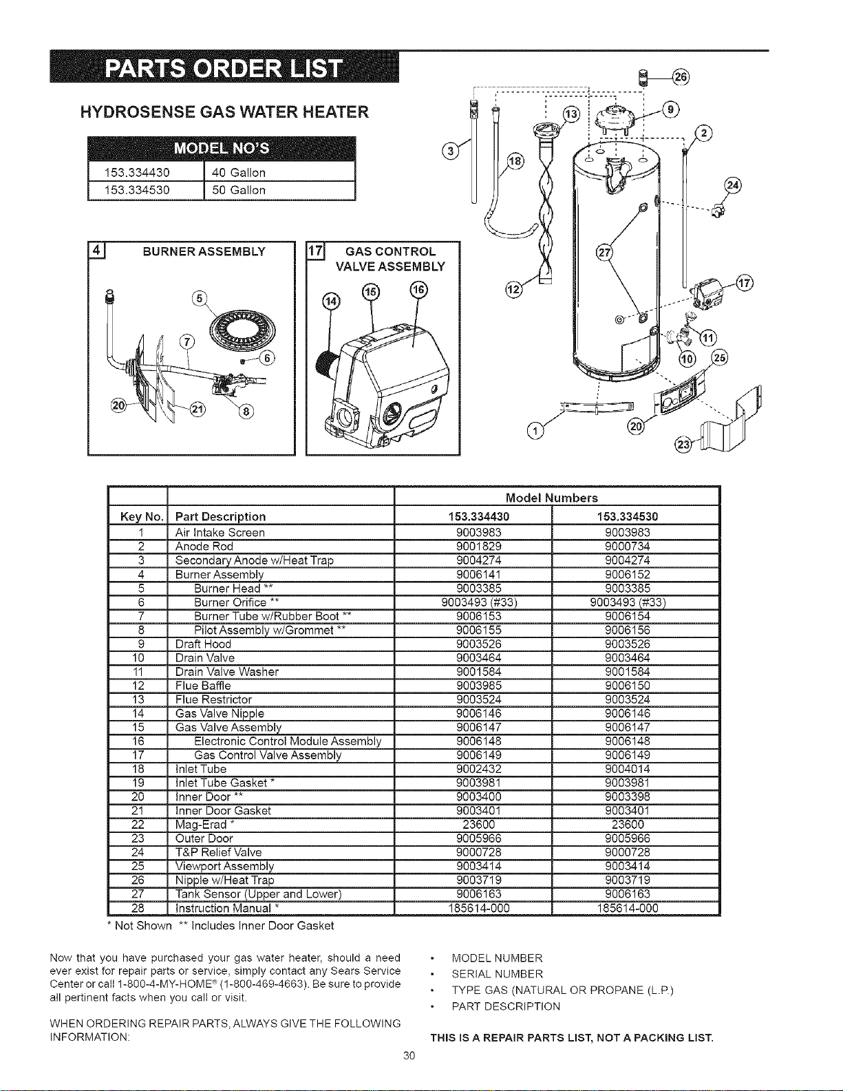
HYDROSENSE GAS WATER HEATER
I 153.334530150Ga,on l
4_j BURNERASSEMBLY
17_ GAS CONTROL
VALVEASSEMBLY
Key No.
1
2
3
4
5
6
7
8
9
10
11
12
13
14
15
16
17
18
19
20
21
22
23
24
25
26
27
28
Part Description
Air Intake Screen
Anode Rod
Secondary Anode w/Heat Trap
Burner Assembly
Burner Head **
Burner Orifice **
Burner Tube w/Rubber Boot **
Pilot Assembly w/Grommet **
Draft Hood
Drain Valve
Drain Valve Washer
Flue Baffle
Flue Restrictor
Gas Valve Nipple
Gas Valve Assembly
Electronic Control Module Assembly
Gas Control Valve Assembly
Inlet Tube
Inlet Tube Gasket *
Inner Door **
Inner Door Gasket
Mag-Erad *
Outer Door
T&P Relief Valve
Viewport Assembly
Nipple w/Heat Trap
Tank Sensor (Upper and Lower)
Instruction Manual *
Model Numbers
153.334430
9003983
9001829
9004274
9006141
9003385
9003493(#33)
9006153
9006155
9003526
9003464
9001584
9003985
9003524
9006146
9006147
9006148
9006149
9002432
9003981
9003400
9003401
23600
9005966
9000728
9003414
9003719
9006163
185614-000
153.334530
9003983
9000734
9004274
9006152
9003385
9003493 (#33)
9006154
9006156
9003526
9003464
9001584
9006150
9003524
9006146
9006147
9006148
9006149
9004014
9003981
9003398
9003401
23600
9005966
9000728
9003414
9003719
9006163
185614-000
Not Shown ** Includes Inner Door Gasket
Now that you have purchased your gas water heater, should a need
ever exist for repair parts or service, simply contact any Sears Service
Center or catl 1-800-4-MY-HOME '_(1-800-469-4663). Be sure to provide
atl pertinent facts when you call or visit.
WHEN ORDERING REPAIR PARTS, ALWAYS GIVE THE FOLLOWING
INFORMATION:
3O
MODEL NUMBER
SERIAL NUMBER
TYPE GAS (NATURAL OR PROPANE (L.P.)
PART DESCRIPTION
THIS IS A REPAIR PARTS LIST, NOT A PACKING LIST.

31
12YEARLIMITED WARRANTY ON WATER HEATER
For twelve years from date of purchase, if this water heater is installed and operated in a single family home in accordance with the
owner's manual instructions and all local applicable codes, Sears wilt supply a free water heater for one that develops a leak,
For the second through twelfth year from purchase date, you must pay the labor cost for installation of the water heater,
3 YEAR LIMITED WARRANTY ON PARTS
For three years from date of purchase, ifthis water heater is installed and operated ina single family home in accordance with the owner's
manual instructions and all local applicable codes, ifa part fails due to materials or workmanship, Sears will supply a free replacement part.
After one year from purchase date, you must pay the labor cost for installation of the part.
1 YEAR EXCLUSIVE KENMORE LABOR WARRANTY
For the first year from the date of purchase, Sears will, free of charge, supply and install new water heater parts for defective ones
or a new water heater for one that develops a leak.
WARRANTY SERVICE
To obtain warranty service, call 1-800-4-MY-HOME P_(1-8004694663). This warranty applies onlywhile this product is in use in the United States.
For commercial, institutional, industrial or residential use by two or more families, the above limited warranty for tanks that leak is
effective for two years from the date of purchase and the above limited parts warranty is effective for one year from the date of purchase.
This warranty gives you specific legal rights and you may also have other rights which vary from state to state.
Sears, Roebuck and Co., Dept. 8!7 WA, Hoffman Estates, IL 60179
The price of your water heater does not include a free checkup service call. On water heater installations arranged by Sears, Sears
warrants the installation.
A charge will be made on service calls due to poor or incomplete installation. These include:
a. Adjusting thermostat b. Leaks in pipes or fittings c. Condensation
MASTER PROTECTION AGREEMENTS
Congratulations on making a smart purchase. Your new Kenmore _'
product is designed and manufactured for years of dependable
operation. But like all products, it may require preventive maintenance
or repair from time to time. That's when having a Master Protection
Agreement can save you money and aggravation.
Purchase a Master Protection Agreement now and protect yourself
from unexpected hassle and expense.
The Master Protection Agreement also helps extend the life of your
new product. Here's what's included in the Agreement:
Expert Service by our 12,000 professional repair specialist.
Unlimited service and no charge for parts and labor on all covered
repairs.
"No-lemon" guarantee - replacement of your covered product if
four or more product failures occur within twelve months.
Product replacement if your covered product can't be fixed.
• Annual Preventive Maintenance Check at your request - no
extra charge.
Fast help by phone - phone support from a Sears technician on
products requiring in-home repair, plus convenient repair scheduling.
Power surge protection against electrical damage due to power
fluctuations.
Rental reimbursement if repair of your covered product takes
longer than promised.
Once you purchase the Agreement, a simple phone call is all that it
takes for you to schedule service. You can call anytime day or night,
or schedule a service appointment online.
Sears has over 12,000 professional repair specialists, who have
access to over 4.5 million quality parts and accessories. That's the
kind of professionalism you can count on to help prolong the life of
your new purchase for years to come. Purchase your Master Protection
Agreement today!
Some limitations and exclusions apply. For prices and additional
information call 1-800-827-6655,
SEARS INSTALLATION SERVICE
For Sears professional Installation of home appliances, garage door
openers, water heaters, and other major home items, in the U.S.A.,
call 1-8004-MY-HOME%
For in-home major brand repair service
Call 24 hours a day, 7 days a week (U.S.A. and Canada)
t -800-4-MY-HOME ®
(1-800-469-4663)
www.sears.com
The model number of your water heater is found on the model rating plate on the front of the water heater.
Sears, Roebuck and Co., Hoffman Estates, IL 60179 U.S.A