30" (76.2 CM) AND 36" (91.4 CM) WALL-
MOUNT CANOPY RANGE HOOD
Installation Instructions and Use & Care Guide
For questions about features, operation/performance parts, accessories or service, call: 1-800-253-1301
In Canada, for assistance, installation and service, call: 1-800-807-6777
or visit our website at www.whirlpool.com or www.whirlpool.ca
HOTTE D’EXTRACTION À MONTAGE MURAL
Instructions d’installation et Guide d’utilisation et d’entretien
1-800-253-1301
1-800-807-6777
or visitez notre site Web au www.whirlpool.com or www.whirlpool.ca
Table of Contents/Table des matières ..................................... 2
LIB0138948A/W11374530A
IMPORTANT: READ AND SAVE THESE INSTRUCTIONS.
FOR RESIDENTIAL USE ONL
Y.
IMPOR
TANT : LIRE ET CONSERVER CES INSTRUCTIONS.
POUR UTILISA
TION RÉSIDENTIELLE UNIQUEMENT
.
2
TABLE OF CONTENTS TABLE DES MATIÈRES
RANGE HOOD SAFETY
You can be killed or seriously injured if you don't immediately
You
can be killed or seriously injured if you don't
follow
All safety messages will tell you what the potential hazard is, tell you how to reduce the chance of injury, and tell you what can
happen if the instructions are not followed.
Your safety and the safety of others are very important.
We have provided many important safety messages in this manual and on your appliance. Always read and obey all safety
messages.
This is the safety alert symbol.
This symbol alerts you to potential hazards that can kill or hurt you and others.
All safety messages will follow the safety alert symbol and either the word “DANGER” or “WARNING.”
These words mean:
follow instructions.
instructions.
DANGER
WARNING
RANGE HOOD SAFETY .................................................................2
INSTALLATION REQUIREMENTS .................................................4
Tools and Parts .............................................................................4
Location Requirements ................................................................4
Venting Requirements ..................................................................5
Electrical Requirements ...............................................................6
INSTALLATION INSTRUCTIONS ...................................................7
Prepare Location ...............................
...........................................7
Install Range Hood .......................................................................8
Connect Vent System ..................................................................8
Make Electrical Connection .........................................................9
Install Vent Covers ........................................................................9
Complete Installation ...................................................................9
RANGE HOOD USE ......................................................................10
Range Hood Controls ................................................................10
R
ANGE HOOD CARE ...................................................................10
Cleaning .....................................................................................10
WIRING DIAGRAM .......................................................................12
ASSISTANCE OR SERVICE .........................................................13
In the U.S.A. ...............................................................................13
In Canada ...................................................................................13
Accessorie
s ................................................................................13
SÉCURITÉ DE LA HOTTE ............................................................15
EXIGENCES D’INSTALLATION ...................................................17
Outils et pièces ...........................................................................17
Exigences d’emplacement .........................................................17
Exigences concernant l’évacuation ...........................................19
Spécifications électriques ..........................................................20
INSTRUCTIONS D’INSTALLATION .............................................21
Préparation de l’emplacement ..................................
.................21
Installation de la hotte ................................................................22
Raccordement du conduit d’évacuation ...................................22
Raccordement électrique ...........................................................23
Installation des cache-conduits .................................................23
Terminer l’installation ..................................................................23
UTILISATION DE LA HOTTE .......................................................24
Commandes de la hotte de cuisinière .......................................24
ENTRETIEN DE LA HOTTE .........................................................24
Nettoyage ..................................................................................
.24
SCHÉMA DE CÂBLAGE ...............................................................26
ASSISTANCE OU DÉPANNAGE ..................................................27
Aux É.-U. ....................................................................................27
Au Canada ..................................................................................27
Accessoires ................................................................................27
3
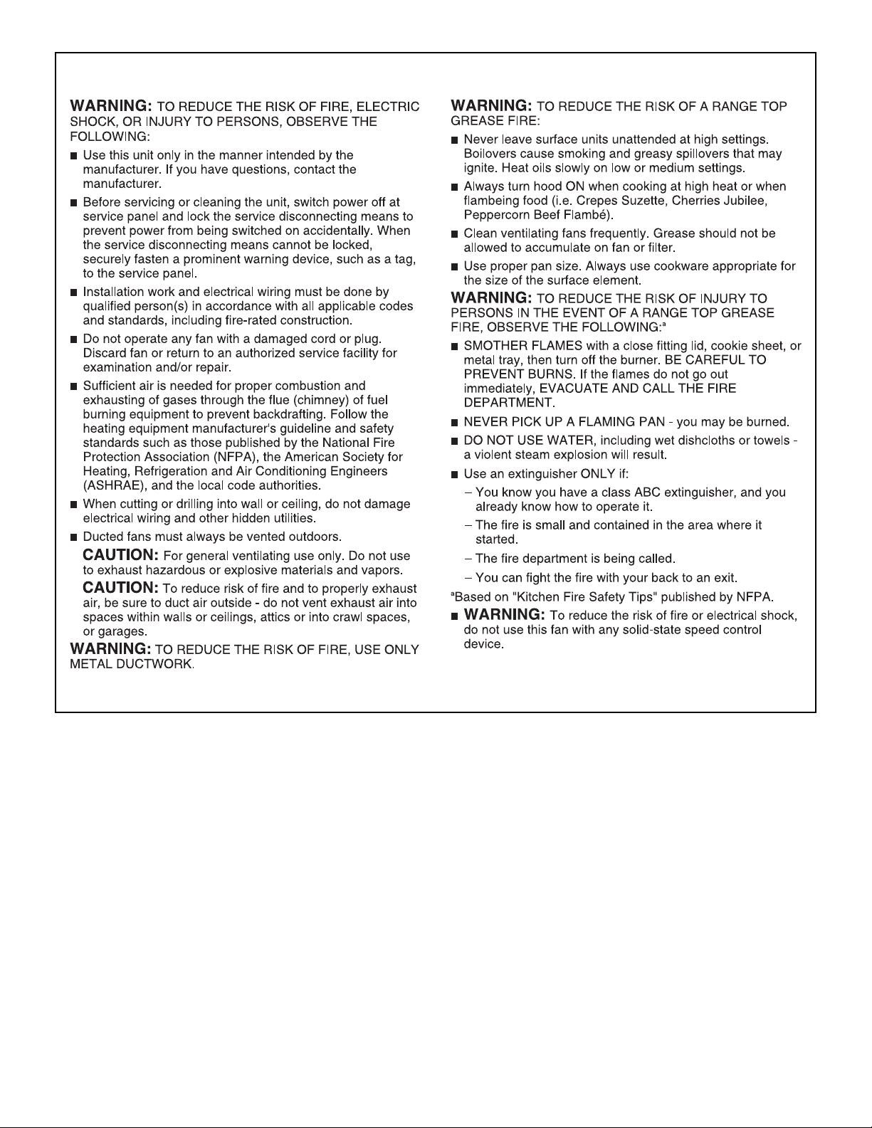
IMPORTANT SAFETY INSTRUCTIONS
READ AND SAVE THESE INSTRUCTIONS
4
INSTALLATION REQUIREMENTS
Tools and Parts
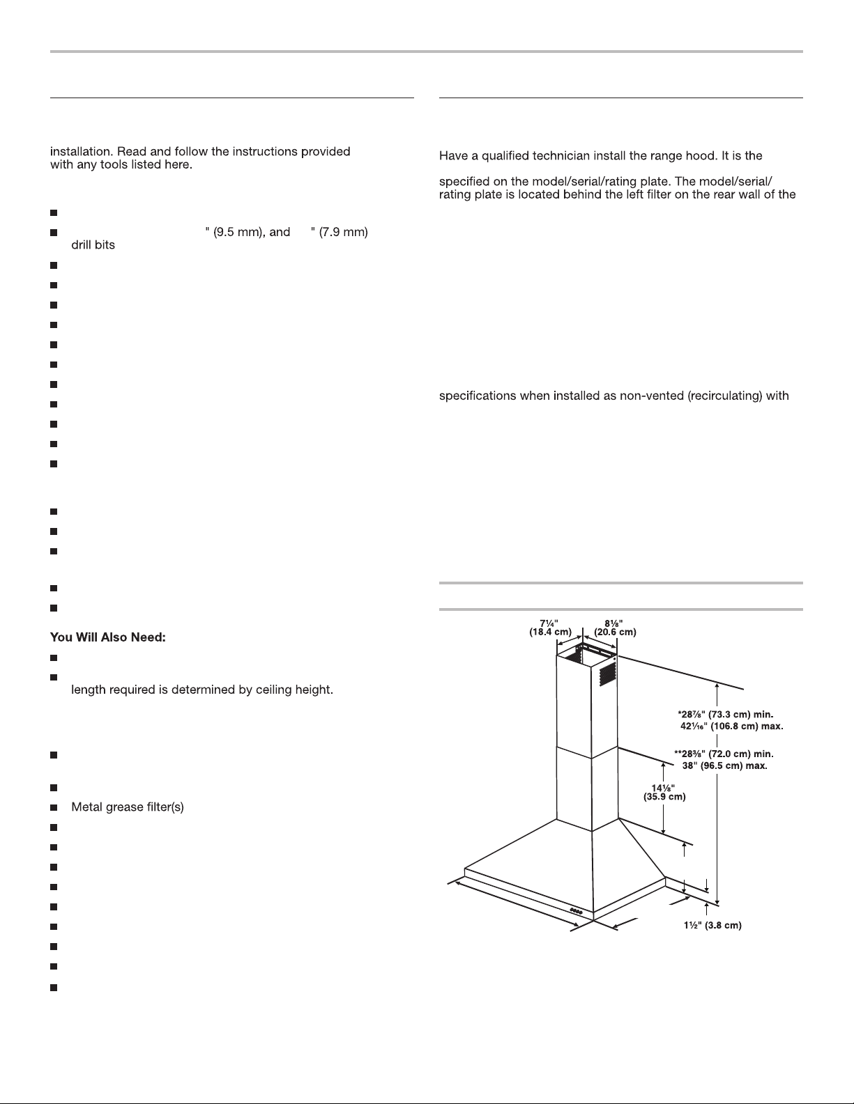
Gather the required tools and parts before starting
Tools Needed
Level
Drill with 1
1
/
4
" (3 cm),
3
/
8
5
/
16
Pencil
Wire stripper or utility knife
Tape measure or ruler
Pliers
Caulking gun and weatherproof caulking compound
Vent clamps
Jigsaw or keyhole saw
Flat-blade screwdriver
Metal snips
Phillips screwdriver
Metric hex key set
Parts Needed
Home power supply cable
1
/
2
" (12.7 mm) UL listed or CSA approved strain relief
3 UL listed wire connectors
For Vented Installations, You Will Also Need:
1 wall or roof cap
Metal vent system
For Non-Vented (Recirculating) Installations,
Recirculation Kit. See “Assistance or Service” section to order.
6" (15.2 cm) diameter round metal vent duct -
Parts Supplied
Remove parts from packages. Check that all parts are included.
Hood canopy assembly with ventilator and light bulbs
installed
Vent transition with back draft dampers installed
Vent cover support bracket
Mounting template
2-piece vent cover
2 - 3.5 x 9.5 mm screws
2 - 2.9 x 6.5 mm screws
6 - 5 x 45 mm mounting screws
2 - 8 x 40 mm wall anchors
4 - 10 x 50 mm wall anchors
T20
®
† Torx
®
adapter
Location Requirements
IMPORTANT: Observe all governing codes and ordinances.
installer's responsibility to comply with installation clearances
vent hood.
Canopy hood location should be away from strong draft areas,
such as windows, doors and strong heating vents.
Cabinet opening dimensions that are shown must be used.
Given dimensions provide minimum clearance.
Grounded electrical supply is required. See “Electrical
Requirements” section.
The canopy hood is factory set for venting through the roof
or wall. For non-vented (recirculating) Installation see “For
Nonvented (recirculating) Installations Only” in “Connect Vent
System” section. Recirculation Kit . See “Assistance or Service”
section to order.
NOTE: This product will not comply with Energy Star
the optional recirculation kit.
All openings in ceiling and wall where canopy hood will be
installed must be sealed.
For Mobile Home Installations
The installation of this range hood must conform to the
Manufactured Home Construction Safety Standards, Title
24 CFR, Part 328 (formerly the Federal Standard for Mobile
Home Construction and Safety, Title 24, HUD, Part 280)
or when such standard is not applicable, the standard for
Manufactured Home Installation 1982 (Manufactured Home
Sites, Communities and Setups) ANSI A225.1/NFPA 501A, or
latest edition, or with local codes.
Product Dimensions
* For non-vented (recirculating) installations
** For vented installations
30" (76.2 cm) or
36" (91.4 cm)
10"
(25.4 cm)
20" (50.8 cm)
®
†TORX and T20 are registered trademarks of Acument Intellectual Properties, LLC.
5
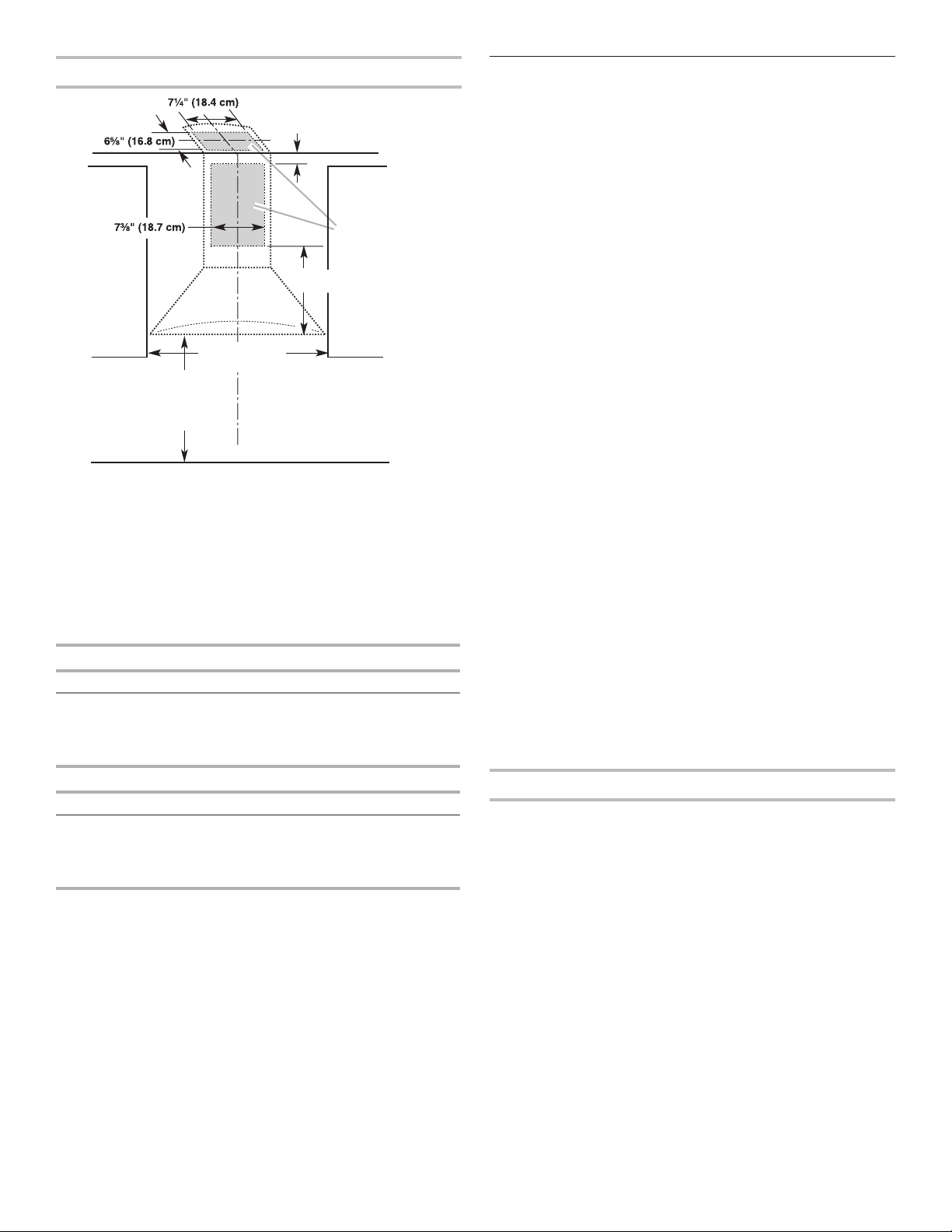
Cabinet Dimensions
* For non-vented (recirculating) installations
IMPORTANT:
Minimum distance “X”: 24" (61 cm)
fromelectriccookingsurface
Minimum distance “X”: 27" (68.6 cm)
fromgascookingsurface
Suggested maximum distance “X”: 36" (91.4 cm)
The chimneys can be adjusted for different ceiling heights.
Seethe following chart.
Vented Installations
Min. ceiling height Max. ceiling height
Electric cooking
surface
7' 5" (2.26 m) 9' 2" (2.79 m)
Gas cooking
surface
7' 8" (2.34 m) 9' 2" (2.79 m)
Non-Vented (Recirculating) Installations
Min. ceiling height Max. ceiling height
Electric cooking
surface
7' 5" (2.26 m) 9' 6" (2.9 m)
Gas cooking
surface
7' 8" (2.34 m) 9' 6" (2.9 m)
*NOTE: The range hood chimneys are adjustable and designed
to meet varying ceiling or soft heights depending on the
distance “X” between the bottom of the range hood and the
cooking surface. For higher ceilings, a Stainless Steel Chimney
Extension Kit Part Number W10337357 is available from your
dealer or an authorized parts distributor. The chimney
extension replaces the upper chimney shipped with the
range hood.
Venting Requirements
(vented models only)
■ Vent system must terminate to the outdoors, except for
nonvented (recirculating) installations..
■ Do not terminate the vent system in an attic or other .
enclosed area.
■ Do not use 4" (10.2 cm) laundry-type wall cap.
■ Use metal vent only. Rigid metal vent is recommended.
Plastic or metal foil vent is not recommended.
■ The length of vent system and number of elbows should be
kept to a minimum to provide efcient performance.
For the Most Efcient and Quiet Operation:
■ Use no more than three 90° elbows.
■ Make sure there is a minimum of 24" (61 cm) of straight
ventbetween the elbows if more than 1 elbow is used.
■ Do not install 2 elbows together.
■ Use clamps to seal all joints in the vent system.
■ The vent system must have a damper. If the roof or wall cap
has a damper, do not use the damper supplied with the .
range hood.
■ Use caulking to seal exterior wall or roof opening
aroundthecap.
■ The size of the vent should be uniform.
Cold Weather Installations
An additional back draft damper should be installed to minimize
backward cold air ow and a thermal break should be installed
to minimize conduction of outside temperatures as part of the
vent system. The damper should be on the cold air side of the
thermal break.
The break should be as close as possible to where the vent
system enters the heated portion of the house.
Makeup Air
Local building codes may require the use of makeup air systems
when using ventilation systems greater than specied CFM of
air movement. The specied CFM varies from locale to locale.
Consult your HVAC professional for specic requirements in your
area.
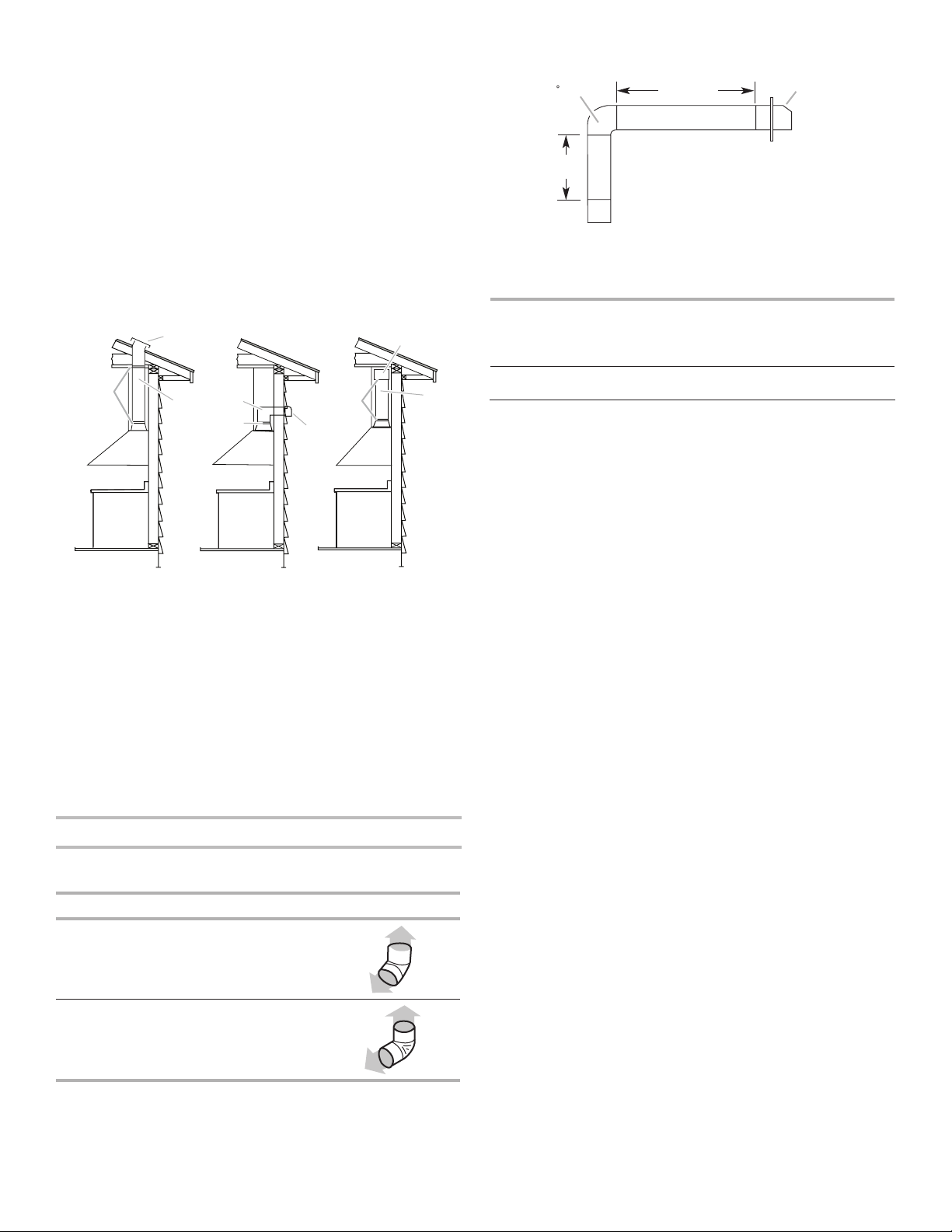
Venting Methods
This canopy hood is factory set for venting through the roof
orwall.
A 6" (15.2 cm) round vent system is needed for installation
(notincluded). The hood exhaust opening is 6" (15.2 cm) round.
NOTE: Flexible vent is not recommended. Flexible vent
creates back pressure and air turbulence that greatly reduce
performance.
Vent system can terminate either through the roof or wall. To
vent through a wall, a 90° elbow is needed.
Rear Discharge
A 90° elbow may be installed immediately above the hood.
2" (5.1 cm) min.
6" (15.2 cm) min.*
Centerline
Side
cabinet
Side
cabinet
Vent and po
wer
supply cable
entry location
Cooking surface
30" (76.2 cm) or
36" (91.4 cm)
15" (38.1 cm)
“X”
bottom of
canopy
to cooking
surface
6
For Non-Vented (Recirculating) Installations
If it is not possible to vent cooking fumes and vapors to the
outside, the hood can be used in the non-vented (recirculating)
version, using a Recirculation Kit (which includes charcoal
lters and a deector). To order, see the “Assistance or Service”
section.
The ducting from this fan to the outside of the building has a
strong effect on the air ow, noise and energy use of the fan.
Use the shortest, straightest duct routing possible for best
performance, and avoid installing the fan with smaller ducts than
recommended.
Insulation around the ducts can reduce energy loss and inhibit
mold growth. Fans installed with existing ducts may not achieve
their rated airow.
*The recirculating version are neither Energy Star nor HVI certified.
Ensure duct joints and exterior penetrations are sealed with
caulk or other similar material to create an air-tight path and to
minimize building heat loss and gain and reduce the potential for
condensation.
Place/wrap insulation around duct and/or fan in order to
minimize possible condensation buildup within the duct, building
heat loss and gain.
Calculating Vent System Length
To calculate the length of the system you need, add the
equivalent feet (meters) for each vent piece used in the system.
Vent Piece 6" (15.2 cm) Round
45° elbow 2.5 ft (0.8 m)
90° elbow 5 ft (1.5 m)
Maximum equivalent vent length is 35 ft (10.7 m).
Example Vent System
The following example falls within the maximum
recommendedvent length of 35 ft (10.7 m).
1 - 90° Elbow = 5 ft (1.5 m)
1 - Wall cap = 0 ft (0 m)
8 ft (2.4 m) straight = 8 ft (2.4 m)
Length of system = 13 ft (3.9 m)
Electrical Requirements
Observe all governing codes and ordinances.
Ensure that the electrical installation is adequate and in
conformance with National Electrical Code, ANSI/NFPA 70
(latest edition), or CSA Standards C22.1-94, Canadian Electrical
Code, Part 1 and C22.2 No. 0-M91 (latest edition) and all local
codes and ordinances.
If codes permit and a separate ground wire is used, it is
recommended that a qualied electrician determine that the
ground path is adequate.
A copy of the above code standards can be obtained from:
National Fire Protection Association
1 Batterymarch Park
Quincy, MA 02169-7471
CSA International
8501 East Pleasant Valley Road
Cleveland, OH 44131-5575
■ A 120 volt, 60 Hz., AC only, 15-amp, fused electrical
circuitisrequired.
■ If the house has aluminum wiring, follow the
procedurebelow:
1. Connect a section of solid copper wire to the
pigtailleads.
2. Connect the aluminum wiring to the added section
of copper wire using special connectors and/or tools
designed and UL listed for joining copper to aluminum.
Follow the electrical connector manufacturer's
recommended procedure. Aluminum/copper connection
must conform with local codes and industry accepted wiring
practices.
■ Wire sizes and connections must conform with the rating of
the appliance as specied on the model/serial/rating plate.
The model/serial/rating plate is located behind the left lter
on the rear wall of the range hood.
■ Wire sizes must conform to the requirements of the National
Electrical Code, ANSI/NFPA 70 (latest edition), or CSA
Standards C22. 1-94, Canadian Electrical Code, Part 1 and
C22.2 No. 0-M91 (latest edition) and all local codes and
ordinances.
Non-Vented
(Recirculating)
Wall Venting
Roof Venting
C
B
A
C
B
A
C
B
A
A. Deflector
B. 6" (15.2 cm)
round vent
C Seal duct joints
with duct tape/
caulk
A. Wall cap
B. 6" (15.2 cm)
round vent
C Seal duct joints
with duct tape/
caulk
A. Roof cap
B. 6" (15.2 cm)
round vent
C Seal duct joints
with duct tape/
caulk
90 Elbo
w
6 ft (1.8 m)
2 ft
(0.6 m)
Wall cap
7
INSTALLATION INSTRUCTIONS
Prepare Location
■ It is recommended that the vent system be installed
beforehood is installed.
■ Before making cutouts, make sure there is proper
clearancewithin the ceiling or wall for exhaust vent.
■ Check your ceiling height and the hood height
maximumbefore you select your hood.
1. Disconnect power.
2. Determine which venting method to use: roof, wall, or
nonvented.
3. Select a at surface for assembling the range hood. Place
covering over that surface.
4. Using 2 or more people, lift range hood onto
coveredsurface.
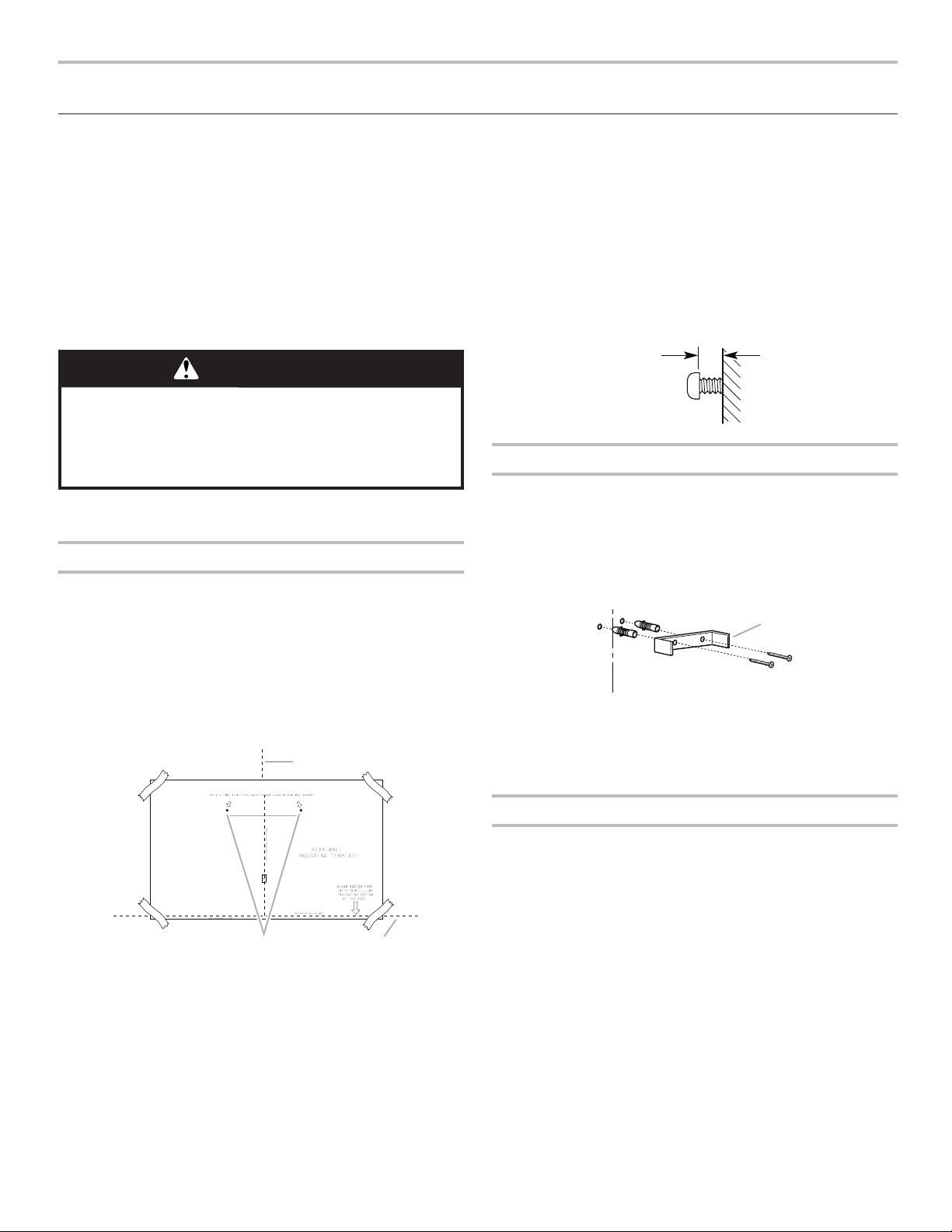
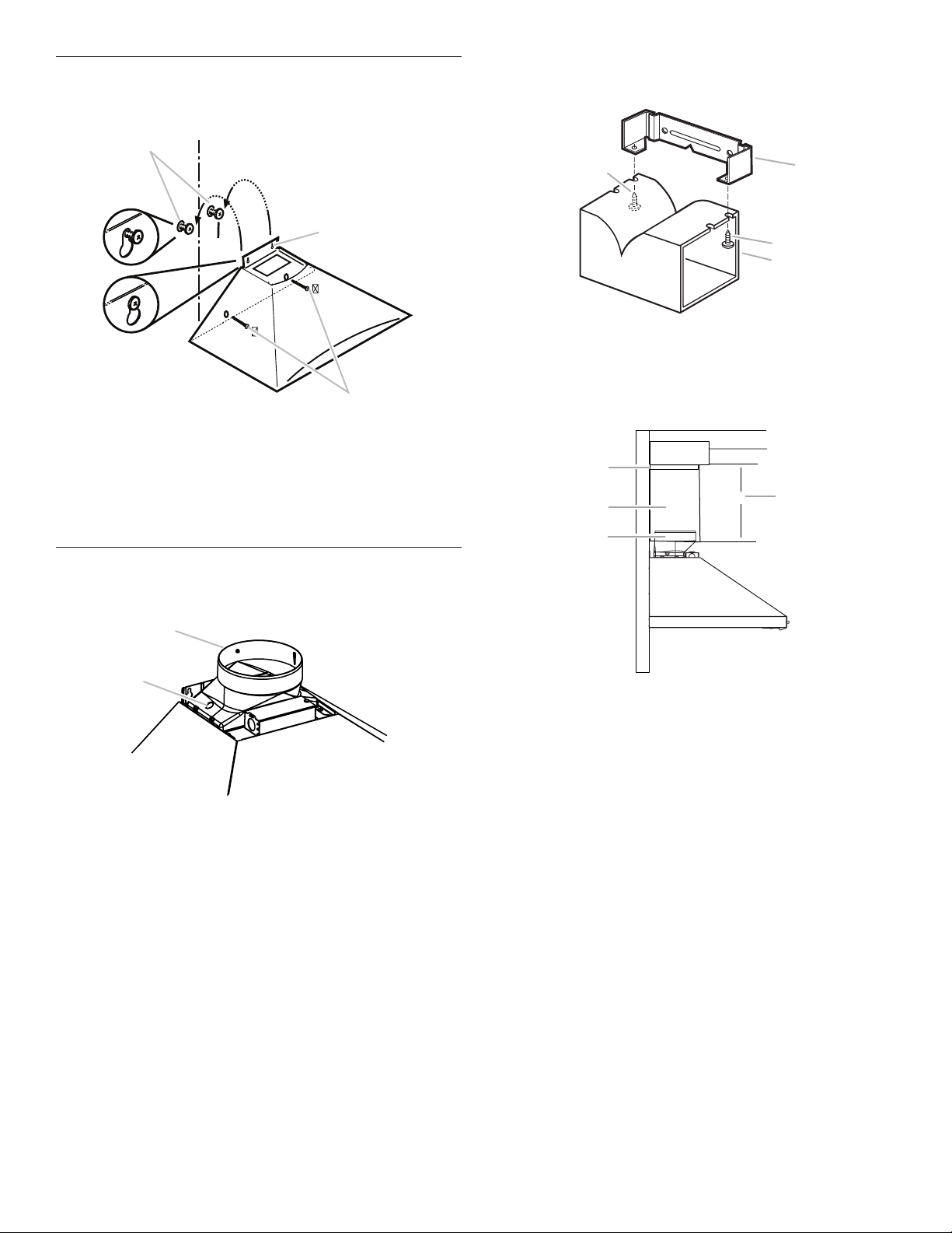
Range Hood Mounting Screws Installation
1. Determine and mark the centerline on the wall where
thecanopy hood will be installed.
2. Select a mounting height between a minimum of 24" (61.0
cm) for an electric cooking surface, a minimum of 27" (68.6
cm) for a gas cooking surface, and a suggested maximum
of 36" (91.4 cm) above the range to the bottom of the hood.
Mark a reference line on the wall.
3. Tape template in place, aligning the template centerline and
bottom of template with hood bottom line and with the
centerline marked on the wall.
4. Mark centers of the fastener locations through the template
to the wall.
IMPORTANT: All canopy mounting screws must be installed
into wood where possible. If there is no wood to screw into,
additional wall framing supports may be required, or use
the (4) 10 x 60 mm wall anchors and 5.4 x 75 mm screws.
Remove the template.
5. For wood, drill
3
/
16
" (4.8 mm) pilot holes at all locations
wherescrews are being installed into wood.
For wall anchors, drill
7
/
16
" (10 mm) holes at all locations
where wall anchors are being used.
6. For wood, install (2) 5 x 45 mm mounting screws. Leave
a
1
/
4
" (6.4 mm) gap between the wall and the back of the
screw head to slide range hood into place.
For wall anchors, install the 10 x 60 mm wall anchors
andinstall the 5.4 x 75 mm screws into the wall anchors.
Tighten until the wall anchors are secure. Back the screws
out
1
/
4
" (6.4 mm).
Vent Cover Support Bracket Installation
Installations using telescoping upper and lower vent
coverassembly
1. Position vent cover bracket on wall about 1⁄8" (3.0 mm) away
from the ceiling.
2. Mark the hole locations.
3. Drill (2)
3
/
8
" (9.5 mm) holes for 8 x 40 mm wall anchors
andinsert anchors ush with the wall.
4. Attach vent cover support bracket to wall.
Complete Preparation
1. Determine and make all necessary cuts in the wall for the
vent system. Install the vent system before installing the
hood. See “Venting Requirements” section.
2. Determine the required height for the home power supply
cable and drill a 1
1
/
4
" (3.2 cm) hole at this location.
3. Run the home power supply cable according to the National
Electrical Code or CSA Standards and local codes and
ordinances. There must be enough ½" conduit and wires
from the fused disconnect (or circuit breaker) box to make
the connection in the hood’s electrical terminal box.
NOTE: Do not reconnect power until installation is complete.
4. Use caulk to seal all openings.
WARNING
Excessive Weight Hazard
Use two or more people to move and install
range hood.
Failure to do so can result in back or other injury.
Ver
tical Centerline
C
L
LLAW RAER
ETALPMET GNITNUOM
EGDE MOTTOB NGILA
ENIL LICNEP HTIW
MOTTOB GNITACIDNI
DOOH EHT FO
thgieH noitallatsnI
TROPPUS LLAW RAER RO SDUTS HGUORHT SELOH TOLIP "61/3 )OWT( 2 LLIRD
eniL latnoziroH
A
C
B
A. Centerline
B. Fastener locations
C. Mounting height reference
¹⁄₄"
(6.4 mm)
A
B
C
D
A. 8 x 40 mm wall anchors
B. Centerline on wall
C. Vent cover support bracket
D. 5 x 45 mm screws
8
Install Range Hood
1. Using 2 or more people, hang range hood on 2 mounting
screws through the mounting slots on back of hood.
2. Remove the grease lter. See “Range Hood Care” section.
3. Level the range hood and tighten upper mounting screws.
4. Install (2) 5 x 45 mm lower mounting screws and tighten.
Usethe optional wall anchors if needed.
Connect Vent System
1. Install transition on top of hood (if removed for shipping)
with(2) 3.5 x 9.5 mm sheet metal screws.
For vented installations only:
1. Fit vent system over transition piece.
2. Seal connection with clamps.
3. Check that back draft dampers work properly.
For non-vented (recirculating) installation only:
1. Assemble the air deector with the duct cover bracket with
2assembly screws provided with the Recirculation Kit.
2. Measure from the bottom of the air deector to the bottom
ofthe hood outlet.
3. Cut the duct to the measured size “X.”
4. Remove the air deector.
5. Slide the duct onto the bottom of the air deector.
6. Place the assembled air deector and duct over
theexhaustoutlet from the hood.
7. Reassemble the air deector to the duct cover bracket
withthe 2 assembly screws.
8. Seal connections with vent clamps.
A
B
C
A. Mounting screws
B. Mounting slots
C. Lower mounting screws
A
B
A. Vent transition
B. 3.5 x 9.5 mm screw
A
C
B
B
A. Vent cover bracket
B. 2.9 x 6.5 mm screws
C. Deflector
X
A
C
D
B
E
A. Air deflector
B. Vent clamp
C. X = length to cut vent duct
D. Vent duct
E. Exhaust outlet
9
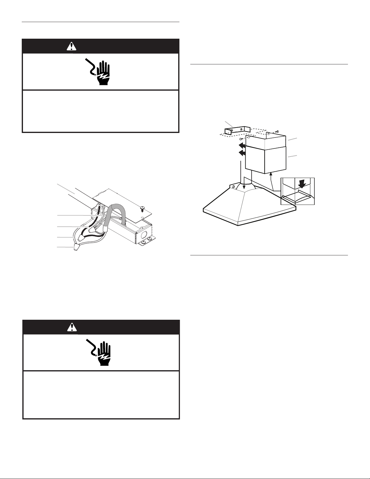
Make Electrical Connection
1. Disconnect power.
2. Remove terminal box cover.
3. Remove the knockout in the terminal box and install
aULlisted or CSA approved
1
/
2
" strain relief.
4. Run home power supply wiring through
1
/
2
" strain relief
intoterminal box.
5. Use UL listed wire connectors and connect white
wires(B)together.
6. Use UL listed wire connectors and connect black
wires(C)together.
7. Connect green (or bare) ground wire from home power
supply to the 2 yellow-green ground wires (D) in terminal
boxusing UL listed wire connectors.
8. Tighten strain relief screw.
9. Install terminal box cover.
10. Reconnect power.
Install Vent Covers
1. When using both upper and lower vent covers, push lower
coverdown onto hood and lift upper cover to ceiling and
installwith (2) 2.9 x 6.5 mm screws.
NOTE: For vented installations, the upper vent cover may be
reversed to hide slots.
Complete Installation
1. For non-vented (recirculating) installations only, install
charcoal lters over the grease lters, using the clips
provided in the kit. See the “Range Hood Care” section.
2. Install metal lters. See the “Range Hood Care” section.
3. Check the operation of the range hood blower and light.
Seethe “Range Hood Use” section.
NOTE: To get the most efcient use from your new range
hood,read the “Range Hood Use” section.
WARNING
Electrical Shock Hazard
Disconnect power before servicing.
Replace all parts and panels before operating.
Failure to do so can result in death or electrical shock.
A
B
C
D
E
A UL listed wire connectors
B. White wires
C. Black wires
D. Green (or bare) wire connected to yellow-green wires
E. Home power supply
WARNING
Electrical Shock Hazard
Electrically ground blower.
Connect ground wire to green and yellow ground wire
in terminal box.
Failure to do so can result in death or electrical shock.
A
B
C
C
D
A. Upper vent cover
B. Lower vent cover
C. 2.9 x 6.5 mm screws
D. Bracket
10
RANGE HOOD USE
The range hood is designed to remove smoke, cooking vapors
and odors from the cooktop area. For best results, start the hood
before cooking and allow it to operate several minutes after
the cooking is complete to clear all smoke and odors from the
kitchen.
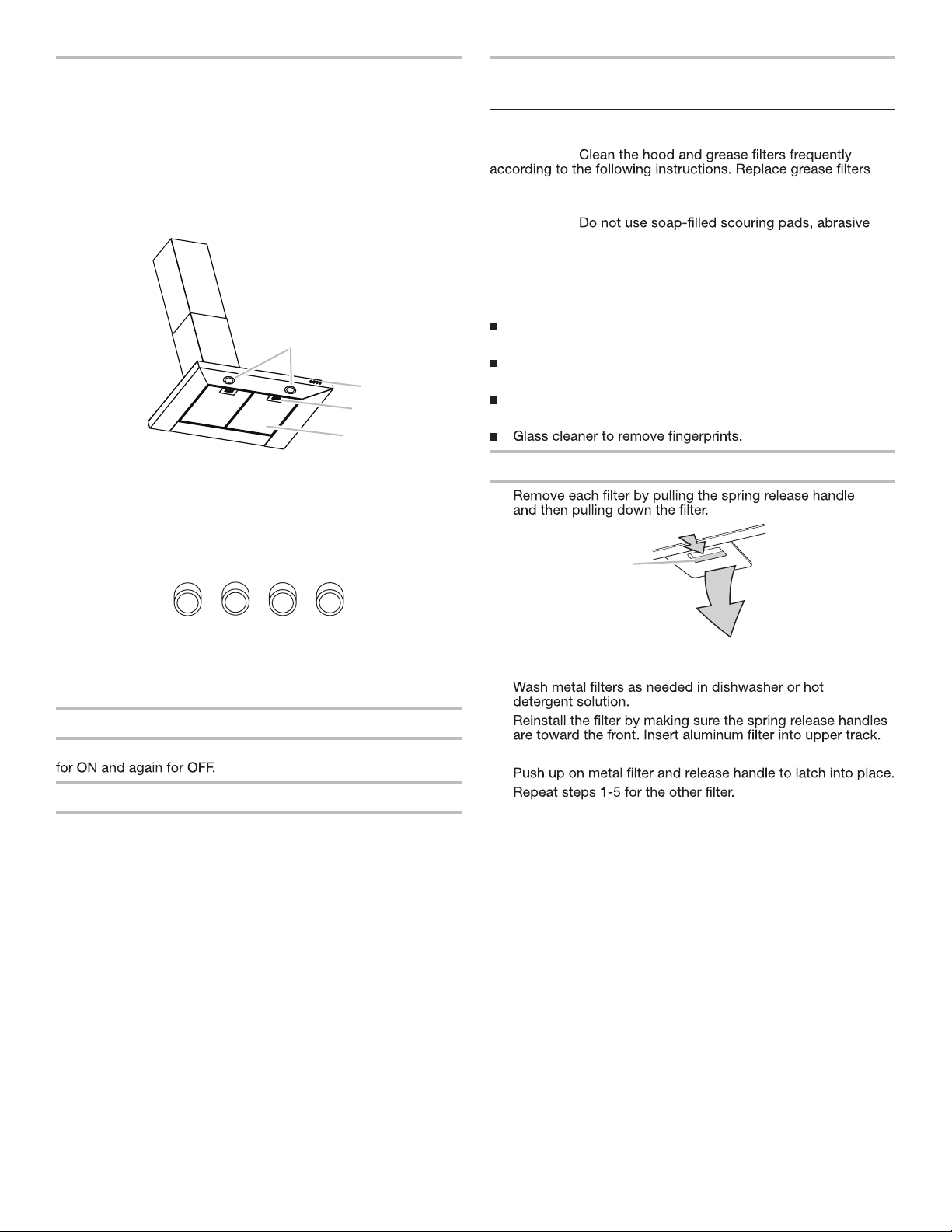
The hood controls are located on the front panel on the right
side of the range hood.
Range Hood Controls
Operating the light
The On/Off light button controls both lights. Press once
Operating the blower
The Blower Speed buttons turn the blower On and control the
blower speed and sound level for quiet operation. The speed
can be changed anytime during fan operation by pressing the
desired blower speed button.
Press the Blower Off button a second time to turn the blower
OFF.
RANGE HOOD CARE
Cleaning
IMPORTANT:
before operating hood.
Exterior Surfaces:
IMPORTANT:
cleaners, Cooktop Polishing Creme, steel wool, gritty washcloths
or paper towels.
To avoid damage to the stainless steel, do not use cleaners that
contain chlorine.
Cleaning Method:
Rub in direction of grain to avoid scratching or damaging the
surface.
Stainless Steel Cleaner and Polish (not included):
See “Assistance or Service” section to order.
Liquid detergent or all-purpose cleaner: Rinse with clean
water and dry with soft, lint-free cloth.
Metal Grease Filter
1.
2.
3.
4. Push in spring release handle.
5.
6.
A
B
C
D
A. LED lamps
B. Blower and light controls
C. Grease filter handle
D. Grease filter
A
B
C
D
A. On/Off light button
B. Blower off and speed minimum button
C. Blower speed medium button
D. Blower speed maximum button
A
A. Spring release handle
11
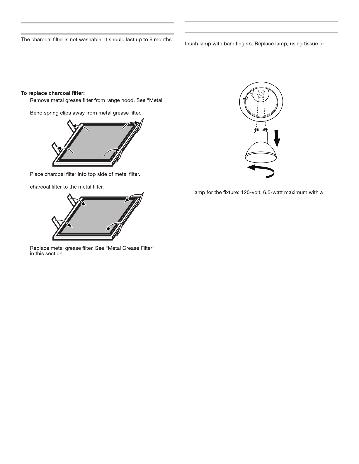
Non-Vented (recirculating) Installation Filters
with normal use. Replace with Charcoal Filter Kit. See the
“Assistance or Service” section for information on ordering.
1.
Grease Filter” in this section.
2.
3.
4. Bend spring clips back into place to secure the
5.
Replacing a LED Lamp
To avoid damage or decreasing the life of the new lamp, do not
wearing cotton gloves to handle lamp.
If new lamps do not operate, make sure the lamps are inserted
correctly before calling service.
1. Disconnect power.
2. Push up on the lens and turn it counterclockwise.
3. Remove and replace it with an appropriate Energy Star
GU10 base. Turn it clockwise to lock it into place.
4. Repeat steps 2-3 for the other lamps if needed.
5. Reconnect power.
NOTE: When used in recirculation mode, To Reduce the Risk of
Fire and Shock use only convertion kit Models:
- Charcoal Filter Kit W10294730
- Recirculation Kit W10349327
12
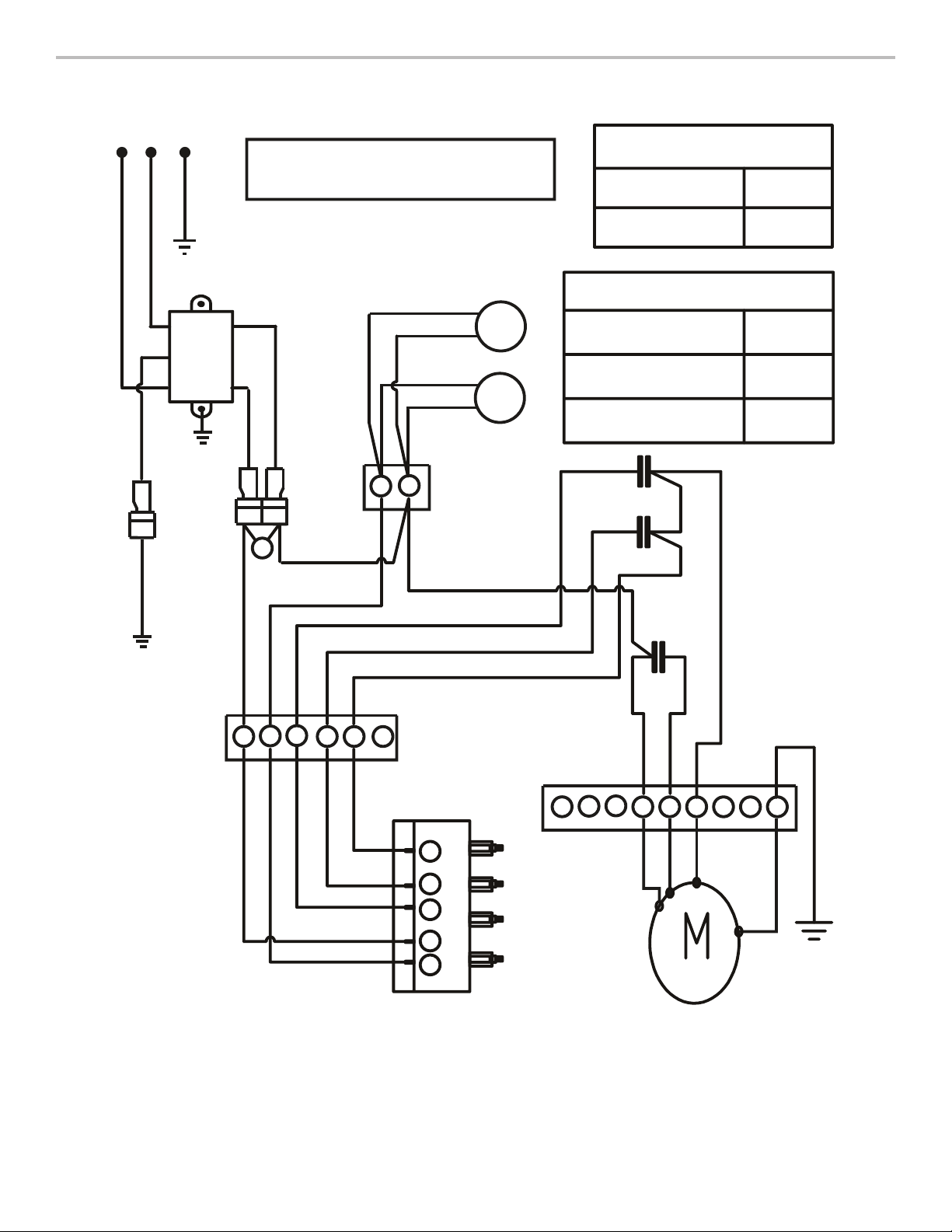
WIRING DIAGRAM
SEL0138394
BK
RD
GR
YL
BR
321456789
321456
4
3 2
L
1
RD
BK
BU
YL/GN
YL/GN
WH
BU
16 uF
BK
S40
WH
25 uF
15 uF
BK
BK
GR
RD
YL
BK
2
1
LED
Z
EMI
FILTER
N
L
GND
Blue - Red
Blue - Black
Power Supply
Frequency
Power Absorotion
120 VA C
60 Hz
144 W
WH
BU
BU
YL
YL
LED
WH
BK
WH
BK
YL/GN
YL/GN
YL/GN
MOTOR RESISTANCE (Ω)
112.1
51.6
MOTOR SPECIFICATIONS
13
ASSISTANCE OR SERVICE
If you need service
Please refer to the warranty page in this manual.
If you need replacement parts
If you need to order replacement parts, we recommend that
precision used to build every new appliance.
In the U.S.A.
Call the Whirlpool Customer eXperience Center toll-free:
1-800-253-1301 or visit our website at www.whirlpool.com.
Our consultants provide assistance with:
Scheduling of service. Whirlpool designated service
provide after-warranty service anywhere in the United States.
Referrals to local dealers.
Installation information.
Use and maintenance procedures.
Accessory and repair parts sales.
Specialized customer assistance (Spanish speaking,
For further assistance
If you need further assistance, you can write to Whirlpool
Corporation with any questions or concerns at:
Whirlpool Brand Home Appliances
Customer eXperience Center
553 Benson Road
Benton Harbor, MI 49022-2692
Please include a daytime phone number in your correspondence.
In Canada
Call the Whirlpool Canada Customer eXperience Centre toll-free:
1-800-807-6777, or visit our website at www.whirlpool.ca.
Our Consultants Provide Assistance With:
Scheduling of Service. Whirlpool designated service
Referrals to local dealers.
Use and maintenance procedures.
Accessory and repair parts sales.
For Further Assistance
If you need further assistance, you can write to Whirlpool
Canada with any questions or concerns at:
Whirlpool Brand Home Appliances
Customer eXperience Centre
200 - 6750 Century Ave.
Mississauga, Ontario L5N 0B7
Please include a daytime phone number in your correspondence.
Accessories
Chimney Extension Kit
Order Part Number EXTKIT18FS
Stainless Steel Cleaner and Polish
Order Part Number 31462A
Charcoal Filter Kit
(for non-vented installations only))
Order Part Number W10294730
Recirculation Kit
(for non-vented installations only)
Order Part Number W10349327

14

LIB0138948A/W11374530A 06/19
®
/™ ©2019 Whirlpool. Used under license in Canada. All rights reserved.
Utilisé sous licence au Canada. Tous droits réservés.