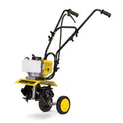
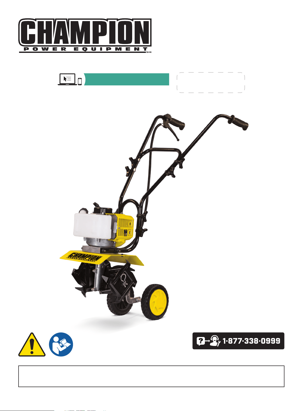
OPERATOR'S MANUAL
MODEL #100882
CULTIVATOR
REV 202010106Champion Power Equipment, Inc., Santa Fe Springs, CA USA
or visit championpowerequipment.com
SAVE THESE INSTRUCTIONS. This manual contains important safety precautions which should be read and understood before operating the product. Failure to do
so could result in serious injury. This manual should remain with the product.
Specifications, descriptions and illustrations in this manual are as accurate as known at the time of publication, but are subject to change without notice.
REGISTER YOUR PRODUCT ONLINE
at championpowerequipment.com

100882 - CULTIVATOR
TABLE OF CONTENTS
2
TABLE OF CONTENTS
Introduction
................................................... 3
Safety Definitions
..........................................3
Important Safety Instructions
.......................4
Things to Do ....................................................... 4
Things Not to Do .................................................. 5
Fuel Safety ........................................................ 6
Safety and Dataplate Labels ...................................... 7
Safety Symbols .................................................... 8
Operation Symbols ................................................ 9
Quickstart Label Symbols......................................... 9
Controls and Features ................................. 10
Cultivator ......................................................... 10
Parts Included .................................................... 11
Assembly ..................................................... 12
Tine Installation or Reinstallation ................................ 12
Wheel Assembly .................................................. 12
Handle Assembly ................................................. 13
Add Fuel .......................................................... 13
Operation ..................................................... 14
Starting and Stopping ............................................ 14
To Stop the Engine ............................................... 15
Special Feature (with Idle Set Properly and the
Engine Running). ................................................... 15
Tips for Extending Engine Life ................................... 16
Cultivating ........................................................ 16
Maintenance ................................................ 17
How to Check, Clean and Change the Air Filter ................. 17
Cleaning Air Filter ................................................ 17
Idle Speed Adjustment ........................................... 17
Clear Blockages From the Fuel Line & Filter .................... 17
Spark Plug ........................................................ 18
Muffler ............................................................ 18
Intake Air Cooling Vent ........................................... 18
Procedures to be Performed After Every 100 Hours of Use .... 18
Maintenance Schedule ........................................... 19
Storage ........................................................ 19
Cultivator Storage ................................................ 19
How to Prepare Your Cultivator for Restarting ..................20
Re-Starting Problems After Storage .............................20
Specifications .............................................. 20
Cultivator Specifications ......................................... 20
Engine Specifications ............................................20
Parts Diagram .................................................... 21
Parts List ......................................................... 22
Engine Parts Diagram ............................................ 23
Engine Parts List ................................................. 24
Troubleshooting ........................................... 25

100882 - CULTIVATOR
INTRODUCTION
3
SAFETY DEFINITIONS
The purpose of safety symbols is to attract your attention to
possible dangers. The safety symbols, and their explanations,
deserve your careful attention and understanding. The safety
warnings do not by themselves eliminate any danger. The
instructions or warnings they give are not substitutes for proper
accident prevention measures.
DANGER
DANGER indicates a hazardous situation which, if not avoided,
will result in death or serious injury.
WARNING
WARNING indicates a hazardous situation which, if not
avoided, could result in death or serious injury.
CAUTION
CAUTION indicates a hazardous situation which, if not avoided,
could result in minor or moderate injury.
NOTICE
NOTICE indicates information considered important, but not
hazard-related (e.g., messages relating to property damage).
INTRODUCTION
Congratulations on your purchase of a Champion Power Equipment
(CPE) product. CPE designs, builds, and supports all of our
products to strict specifications and guidelines. With proper
product knowledge, safe use, and regular maintenance, this
product should bring years of satisfying service.
Every effort has been made to ensure the accuracy and
completeness of the information in this manual at the time of
publication, and we reserve the right to change, alter and/or
improve the product and this document at any time without prior
notice.
CPE highly values how our products are designed, manufactured,
operated, and serviced as well as providing safety to the operator
and those around the cultivator. Therefore, it is IMPORTANT to
review this product manual and other product materials thoroughly
and be fully aware and knowledgeable of the assembly, operation,
dangers and maintenance of the product before use. Fully
familiarize yourself, and make sure others who plan on operating
the product fully familiarize themselves too, with the proper safety
and operation procedures before each use. Please always exercise
common sense and always err on the side of caution when
operating the product to ensure no accident, property damage,
or injury occurs. We want you to continue to use and be satisfied
with your CPE product for years to come.
When contacting CPE about parts and/or service, you will need to
supply the complete model and serial numbers of your product.
Transcribe the information found on your product’s nameplate
label to the table below
CPE TECHNICAL SUPPORT TEAM
1-877-338-0999
MODEL NUMBER
100882
SERIAL NUMBER
DATE OF PURCHASE
PURCHASE LOCATION
100882 - CULTIVATOR
IMPORTANT SAFETY INSTRUCTIONS
4
IMPORTANT SAFETY INSTRUCTIONS
WARNING
Cancer and Reproductive Harm – www.P65Warnings.ca.gov
DANGER
Using an engine indoors CAN KILL YOU IN MINUTES. Engine
exhaust contains carbon monoxide. This is a poison you cannot
see or smell.
NEVER use inside a home or garage, EVEN IF doors and
windows are open.
ONLY use OUTSIDE and far away from windows, doors,
and vents.
Install battery-operated carbon monoxide alarms or plug-in
carbon monoxide alarms with battery back-up according to the
manufacturer’s instructions.
DANGER
Rotating parts can entangle hands, feet, hair, clothing and/or
accessories. Traumatic amputation or severe laceration can
result.
Keep hands and feet away from rotating parts. Tie up long hair
and remove jewelry. Operate equipment with guards in place.
DO NOT wear loose-fitting clothing, dangling drawstrings or
items that could become caught.
DANGER
Sparks can result in fire or electrical shock.
When servicing the engine:
– Disconnect the spark plug wire and place it where it cannot
contact the plug. DO NOT check for spark with the plug
removed. Use only approved spark plug testers.
WARNING
Running engines produce heat. Severe burns can occur on
contact. Combustible material can catch fire on contact.
DO NOT touch hot surfaces. Avoid contact with hot exhaust
gases. Allow equipment to cool before touching. Maintain
at least 3 ft. (91.4 cm) of clearance on all sides to ensure
adequate cooling. Maintain at least 5 ft. (1.5 m) of clearance
from combustible materials.
WARNING
Rapid retraction of the starter cord will pull hand and arm
towards the engine faster than you can let go. Unintentional
startup can result in entanglement, traumatic amputation or
laceration. Broken bones, fractures, bruises or sprains could
result.
When starting engine, pull the starter cord slowly until
resistance is felt and then pull rapidly to avoid kickback.
Things to Do
– Always keep a firm grip on both handles while the tines are
moving and/or the engine is running.
BE AWARE!! The tines may coast after throttle trigger is
released. Make sure tines have come to a complete stop and
engine is off before letting go of the cultivator handles.
– Always maintain a firm footing and good balance.
Do not overreach while operating the cultivator. Before you
start to use the cultivator, check the work area for obstacles
that might cause you to lose your footing, balance or control of
the machine.
– Thoroughly inspect the area where equipment is to be used
and remove all objects, that can be thrown by the machine or
cause it to jam.
– Keep all bystanders, children, and pets at least
50 ft. (15.2 m) away.
– Always stay alert. Watch what you are doing and use common
sense. Do not operate unit when fatigued.
– Always dress properly. Do not wear loose clothing or jewelry,
they might get caught in moving parts. Use sturdy gloves.
Gloves reduce the transmission of vibration to your hands.
Prolonged exposure to vibration can cause numbness, fatigue
and other ailments.
– While working, always wear substantial footwear and long
trousers. Do not operate the equipment when barefoot or
wearing open sandals.
– Always wear ear and eye protection.Eye protection must meet
ANSI Z87.1. To avoid hearing damage, we recommend hearing
protection be worn whenever using the equipment.

100882 - CULTIVATOR
IMPORTANT SAFETY INSTRUCTIONS
5
– To reduce fire hazard, keep the engine, and petrol/gas storage
area free of vegetative material and excessive grease.
– Start the engine carefully, according to the instructions and
with feet well away from the tines.
– Always operate the cultivator with good visibility
– Keep all nuts, bolts and screws tight to be sure the equipment
is in safe working condition.
– Use extreme caution when reversing or pulling the machine
towards you.
– Stop the engine and disconnect the spark plug before
unclogging the tines and when making any repairs,
adjustments, or inspections.
– Work only in daylight or good artificial light.
– Always be sure of your footing on slopes.
– Exercise extreme caution when changing direction on slopes.
– Always keep a safe distance between two or more people
when working together.
– Always inspect your unit before each use and ensure that all
handles, guards and fasteners are secure, operating, and in
place.
– Always maintain and examine your cultivator with care. Follow
maintenance instructions given in manual.
– Always use fresh gasoline. Stale gasoline can cause engine
damage.
– Always store fuel in containers specifically designed for that
purpose.
– Always pull starter cord slowly until resistance is felt. Then pull
cord rapidly to avoid kickback and prevent arm or hand injury.
– Stop the engine whenever you leave the machine.
– Allow the engine to cool before storing in any enclosure.
– If the fuel tank needs to be drained, this should be done
outdoors.
Things Not to Do
– Don’t use the cultivator with one hand. Keep both hands on the
handles with fingers and thumbs encircling the handles while
tines are moving and engine is running.
– Don’t put hands or feet near or under tines.
– Do not use near underground electric cables, telephone lines,
pipes, or hoses. If in doubt, contact your utility or telephone
company to locate underground services.
– Don’t overreach. Keep a good footing at all times.
– Don’t run with the machine only walk.
– Don’t work on excessively steep slopes.
– Don’t attempt to clear tines while they are moving. Never try to
remove jammed material before switching the engine off and
making sure the tines have stopped completely.
– Don’t allow children to operate this cultivator.
– Don’t allow adults to operate the equipment without proper
instruction.
– Don’t operate while under the influence of alcohol or drugs.
– Don’t fuel, refuel or check fuel while smoking, or near an open
flame or other ignition source. Stop engine and be sure it is
cool before refueling.
– Don’t leave the engine running while the cultivator is
unattended. Stop engine before putting the cultivator down or
while transporting from one place to another.
– Don’t refuel, start or run this cultivator indoors or in an
improperly ventilated area.
– Don’t run engine when electrical system causes spark
outside the cylinder. During periodic checks of the spark plug,
keep plug a safe distance from cylinder to avoid burning of
evaporated fuel from cylinder.
– Don’t check for spark with spark plug or plug wire removed.
Use an approved tester.
– Don’t crank engine with spark plug removed unless spark plug
wire is disconnected. Sparks can ignite fumes.
– Don’t run engine when the odor of gasoline is present or other
explosive conditions exist.
– Don’t operate the unit if gasoline is spilled. Clean up spill
completely before starting engine.
– Don’t operate your cultivator if there is an accumulation of
debris around the muffler, and cooling fins.
– Don’t touch hot mufflers, cylinders or cooling fins as contact
may cause serious burns.
– Don’t change the engine governor setting or over speed the
engine.

100882 - CULTIVATOR
IMPORTANT SAFETY INSTRUCTIONS
6
Fuel Safety
DANGER
GASOLINE AND GASOLINE VAPORS ARE HIGHLY
FLAMMABLE AND EXPLOSIVE.
Fire or explosion can cause severe burns or death.
Gasoline and gasoline vapors:
– Gasoline is highly flammable and explosive.
– Gasoline can cause a fire or explosion if ignited.
– Gasoline is a liquid fuel but it’s vapors can ignite.
– Gasoline is a skin irritant and needs to be cleaned up
immediately if spilled on skin or clothes.
– Gasoline has a distinctive odor, this will help detect potential
leaks quickly.
– Gasoline expands or contracts with ambient temperatures.
Never fill the gasoline tank to full capacity, as gasoline needs
room to expand when temperatures rise.
– In the case of any petroleum gasoline fire, flames should never
be extinguished unless the fuel supply valve can be turned
OFF. By not doing so, if a fire is extinguished and the supply
of fuel is not turned OFF, an explosion hazard could be created.
When adding or removing gasoline:
– DO NOT light or smoke cigarettes.
– Always turn the engine off and let cool for a minimum of two
minutes before removing the gasoline cap. Afterwards, loosen
gasoline cap to relieve pressure from the gasoline tank.
– Only fill or drain gasoline outdoors in a well-ventilated area.
– DO NOT pump gasoline directly into the engine at the gas
station. Always use an approved fuel container to transfer the
gasoline to the engine.
– DO NOT overfill the gasoline tank.
– Always keep gasoline away from sparks, open flames, pilot
lights, heat and other sources of ignition.
When starting the cultivator:
– DO NOT attempt to start a damaged engine.
– Always make certain that the gasoline cap, air filter, spark
plug, fuel lines and exhaust system are properly secured,
connected and in place.
– Always allow spilled gasoline to evaporate fully before
attempting to start the engine.
– Make certain that the cultivator is resting firmly on level
ground.
When operating the cultivator:
– DO NOT move or tip the cultivator during operation.
– DO NOT tip the cultivator or allow fuel or oil to spill.
When transporting or servicing the cultivator:
– Make certain that the fuel valve is in the OFF position and the
gasoline tank is empty.
– Disconnect the spark plug wire.
When storing the cultivator:
– Store away from sparks, open flames, pilot lights, heat and
other sources of ignition.
– Do not store cultivator or gasoline near furnaces, water
heaters, or any other appliances that produce heat or have
automatic ignitions.
WARNING
Never use a gasoline container, gasoline tank, or any other fuel
item that is broken, cut, torn or damaged.
100882 - CULTIVATOR
IMPORTANT SAFETY INSTRUCTIONS
7
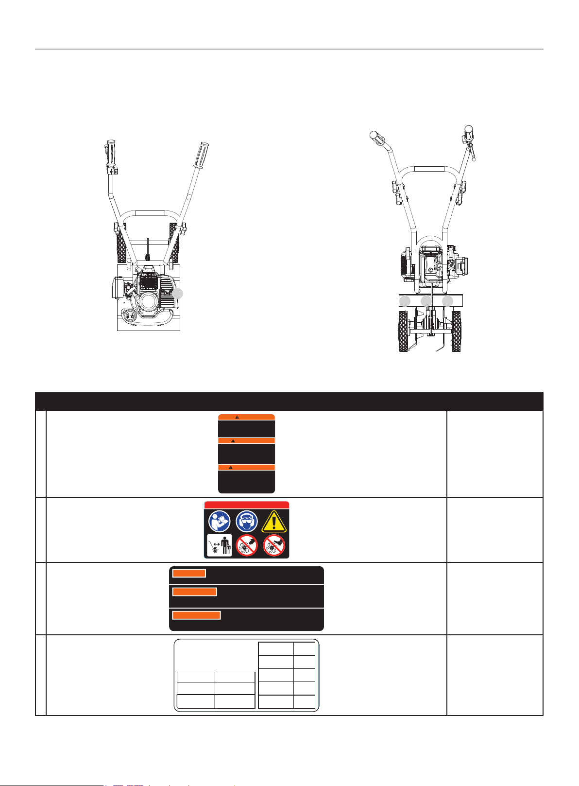
Safety and Dataplate Labels
These labels warn you of potential hazards that can cause serious injury. Read them carefully.
If a label comes off or becomes hard to read, contact Technical Support Team for possible replacement.
LABEL DESCRIPTION
A
WARNING
AVERTISSEMENT
WARNING
ADVERTENCIA
To reduce the risk of fires , burns, explosions or injuries,
the user must read and understand the operator’s
manual. DO NOT use without the han dle in its place.
While servicing the unit, only use identical replacement
parts. Risk of eye injuries. Use protective goggles.
Para reducir el ries go de incendi o, quemaduras,
explosiones o lesiones, el usuario debe leer y
comprender el manual del operador. No la use sin el
mango en su lugar. Al dar servicio a la unidad, sólo us e
piezes de respuesto identicas. Riesgo de lesiones
oculares. Use gafas de seguridad.
Pour réduire le risque d’incendies, de brûlur es,
d'explosions ou de blessures, l’utilisateur doit lire et
comprendre le manuel de l'opérateur. NE PAS utiliser
sans la poignée à sa place. Lors de l'en tretien de
l’appareil, utilisez uniquement les pièces de rechange
identiques. Risque de blessures aux yeux. Utilisez des
lunettes de protection.
1989-L-SF-B
Injury Risk
B
1988-L-SF-A
DANGER PELIGRO DANGER
50FT. (15M)
Safety Icons
C
WARNING
Operation of this equipment may create sparks that can start fires around
dry vegetation. A spark arrestor may be required. The operator should
contact local fire agencies for laws or regulations relating to fire prevention requirements.
ADVERTENCIA
Operación de este equipo puede crear chispas que pueden
iniciar incendios en vegetación seca. Un parachispas puede ser
requerido. El operador debería contactar las agencias locales de incendios para leyes o
regulaciones relacionadas con requisitos de prevención de incendios.
AVERTISSEMENT
Le fonctionnement de cet équipement peut créer des
étincelles qui peuvent déclencher des incendies autour de la
végétation sèche. Un pare-étincelles peut être nécessaire. L'utilisateur doit communiquer avec
le service d'incendie local pour les lois et les règlements relatifs à la prévention des incendies.
1047-L-SF-C
Combustion
D
CHAMPION POWER EQUIPMENT, INC.
12039 SMITH AVENUE
SANTA FE SPRINGS, CA 90670
USA / É.-U.
1-877-338-0999
WWW.CHAMPIONPOWEREQUIPMENT.COM
MADE IN CHINA / FABRIQUÉ EN CHINE
ENGINE NO.
N° DE MOTEUR
DISPLACEMENT
CYLINDRE
TYPE
TYPE
START
DÉMARRAGE
FUEL:OIL
CARBURANT : HUILE
MANUFACTURE DATE
DATE DE FABRICATION
SERIAL NO.
N° DE SÉRIE
MODEL / MODÈLE
2171-L-PR-A
100882
1E40F-2E
43cc
2-STROKE
RECOIL
50:1
XXXXXXXXXXXX
XXXX
Dataplate
Top
A
BC D
Back

100882 - CULTIVATOR
IMPORTANT SAFETY INSTRUCTIONS
8
Safety Symbols
Some of the following symbols may be used on this product. Please study them and learn their meaning. Proper interpretation of these
symbols will allow you to more safely operate the product.
SYMBOL MEANING
Read Operator’s Manual. To reduce the risk of injury, user must read and understand operator’s manual
before using this product.
Eye and Ear Protection. Always wear safety goggles or safety glasses with side shields, and as
necessary a full face-shield as well as full ear protection when operating this product. Always wear eye
protection with side shields marked to comply with ANSI Z87.1.
Safety Alert. This machine was built to be operated according to the safe operation practices in this
manual. As with any type of power equipment, carelessness or error on the part of the operator can
result in serious injury. This machine is capable of amputating fingers, hands, toes and feet and throwing
foreign objects. Failure to observe the safety instructions could result in serious injury or death.
Rotating Tines. Avoid injury from rotating tines. Keep hands away.
Rotating Tines. Avoid injury from rotating tines. Keep feet away.
Hot Surface. To reduce the risk of injury or damage, avoid contact with any hot surface.
Clearance. Keep all objects including others at least 50 feet (15 m) from this machine. Only one person
should operate the cultivator.
100882 - CULTIVATOR
IMPORTANT SAFETY INSTRUCTIONS
9
Operation Symbols
Some of the following symbols may be used on this product. Please study them and learn their meaning. Proper interpretation of these
symbols will allow you to more safely operate the product.
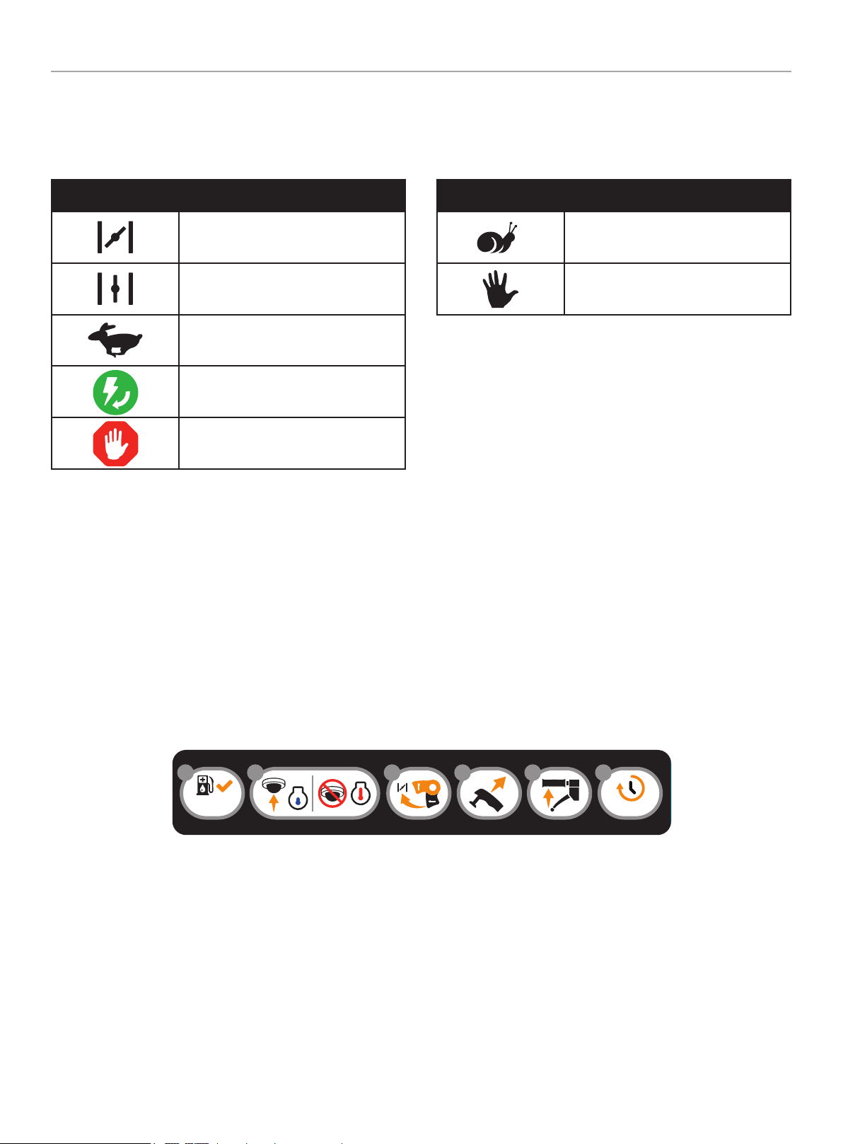
SYMBOL MEANING
Choke
Run
Throttle Lever: FAST
Engine ON / START / RUN
Engine OFF or STOP
SYMBOL MEANING
Throttle Lever: SLOW
Hand placement
Quickstart Label Symbols
Some of the following symbols may be used on this product. Please study them and learn their meaning. Proper interpretation of these
symbols will allow you to more safely operate the product.
Starting the Engine
1. Check fuel. Make sure fuel-to-oil mixture is 50:1 and add if
necessary.
2. Primer bulb:
2a. For cold starts, press primer bulb 7-10 times.
2b. For warm starts, DO NOT press primer bulb.
3. Move choke lever to the CHOKE position.
4. Holding the unit firmly, pull starter handle until the engine
starts.
5. Press the throttle trigger when the engine starts. This will
automatically move the choke lever to the RUN position. Once
the engine is running, release throttle trigger.
6. Allow the engine to idle for 30 seconds.
31
50 : 1
2
7-10X
6
30 s
54
1984-L-OP-B
100882 - CULTIVATOR
CONTROLS AND FEATURES
10
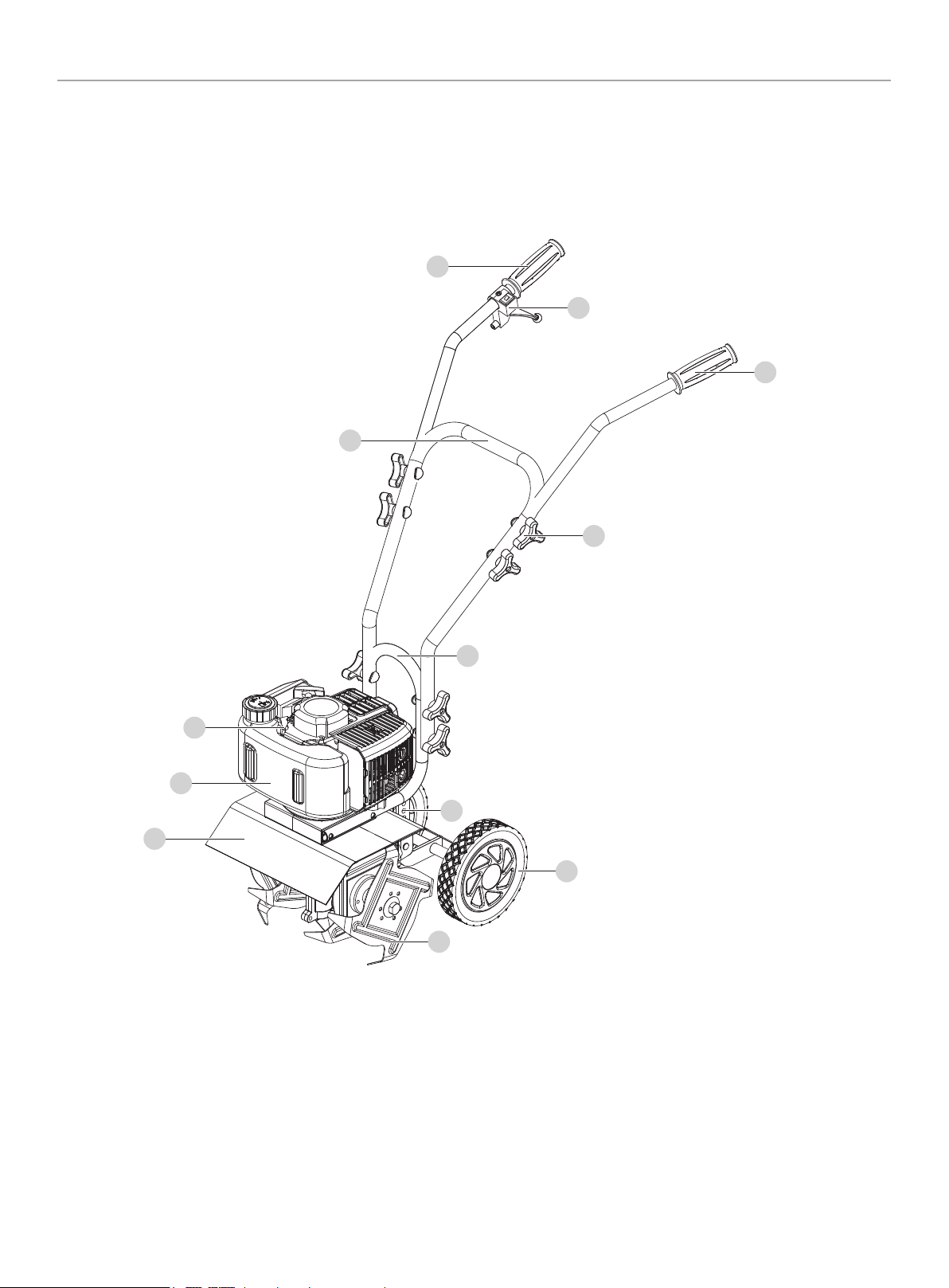
CONTROLS AND FEATURES
Read this operator’s manual before operating your cultivator. Familiarize yourself with the location and function of the controls and
features. Save this manual for future reference.
Cultivator
1. Fender Guard
2. Fuel Tank – 0.3 gal. (1.1 L), 50:1 ratio
3. Engine – 43cc
4. Middle Handle
5. Right Handle
6. Throttle
7. Left Handle
8. Knob Nut
9. Lower Handle
10. Axle Assembly
11. Wheel
12. Tine Assembly
1
2
3
4
5
6
7
8
9
10
11
12
100882 - CULTIVATOR
CONTROLS AND FEATURES
11
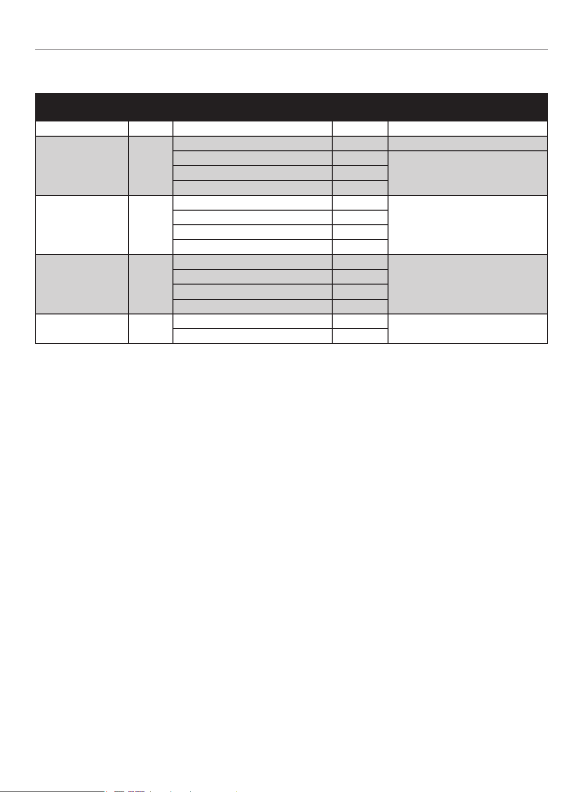
Parts Included
Assembly Parts
Part Part Qty. Hardware Needed
Hardware
Qty.
Tool Needed
Tines 4 R Clip 2 Needle Nose Plier
Wheel Assembly 1
Bolt M6 × 12 2 10mm Wrench or Socket
Washer Ø6 2
N/AWheels 2
Hubcaps 2
Lower Handle 1
Curved Head Bolt M8 × 45 4
N/A
Lock Washer Ø8 4
Flat Washer Ø8 4
Knob-Nut M8 4
Upper Handle 1
Curved Head Bolt M8 × 45 4
N/A
Lock Washer Ø8 4
Flat Washer Ø8 4
Knob-Nut M8 4
Axle Assembly 1
R Clip 1
Needle Nose Plier
Clevis Pin 8 × 18 1
Accessories:
– Spark Plug Socket
– Wrench, 8mm/10mm
– Hex Key, 4mm
– Hex Key, 5mm
– 2 Stroke Oil, 2.6 fl. oz. (76 ml)
100882 - CULTIVATOR
ASSEMBLY
12
ASSEMBLY
Your cultivator requires some assembly. This unit ships from our
factory without oil. It must be properly serviced with fuel and oil
before operation.
If you have any questions regarding the assembly of your
cultivator, call our Technical Support Team at 1-877-338-0999.
Please have your serial number and model number available.
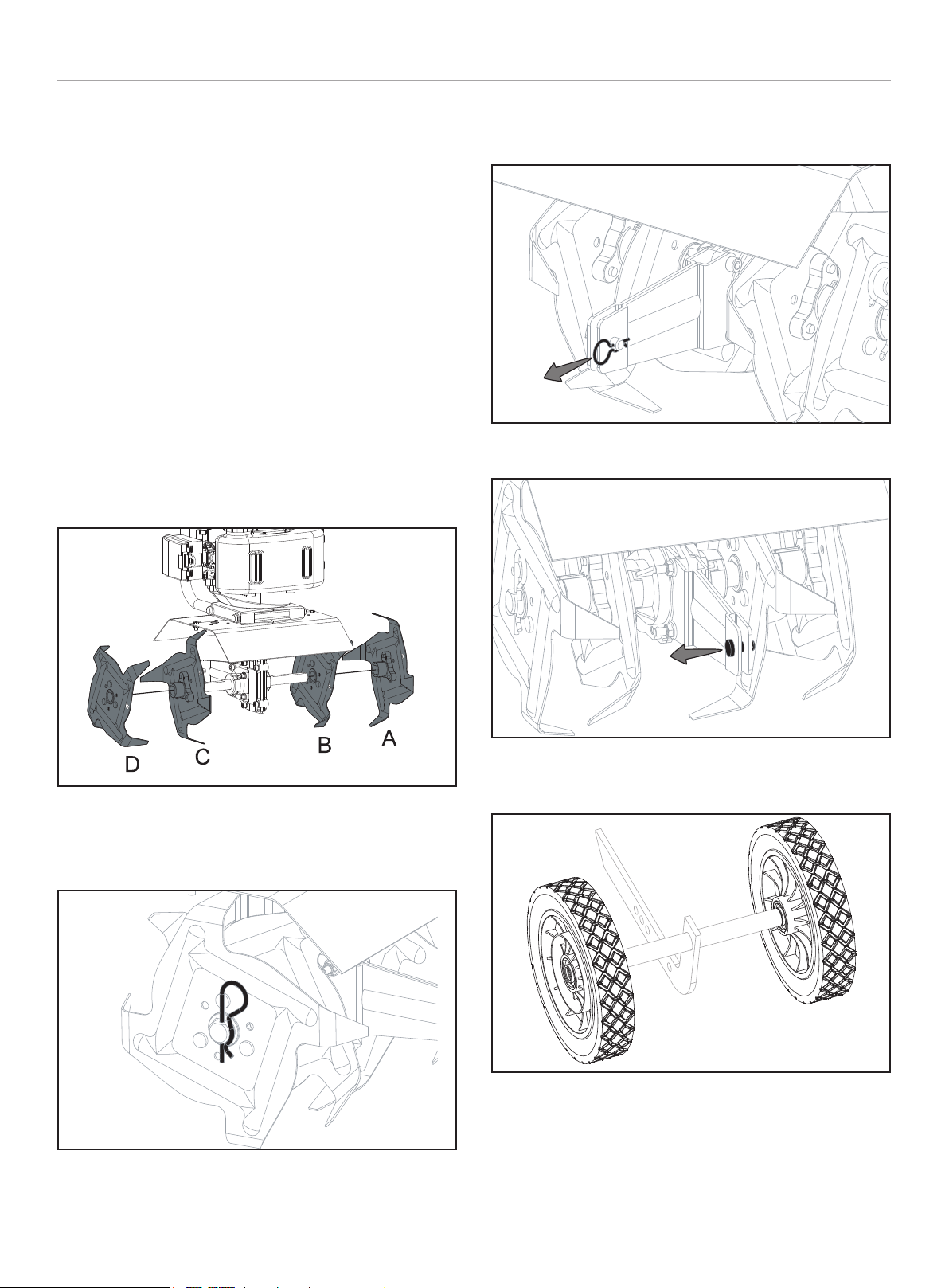
Tine Installation or Reinstallation
1. First, slide the inside tines onto each end of the tine shaft.
One inside tine is stamped with a “B” and the other is
stamped with a “C”.
2. Slide the outside tine “A” and tine “D” onto each end of the
shaft next. The tines should be installed in the correct order
so that they are positioned right to left A, B, C, D, as viewed
from the front of the cultivator. Make sure that the hub collars
on both the right and left pairs of tines face each other so that
there is adequate spacing between the tine blades.
3. Slide a washer on each side.
4. Insert the R clip into the holes at each end of the tine shaft to
lock the tines into place.
Wheel Assembly
1. Remove the R clip from the clevis pin.
2. Remove the clevis pin from the axle assembly.
3. Place wheel on each end of the axle. Note installation
direction - ring faces outwards.
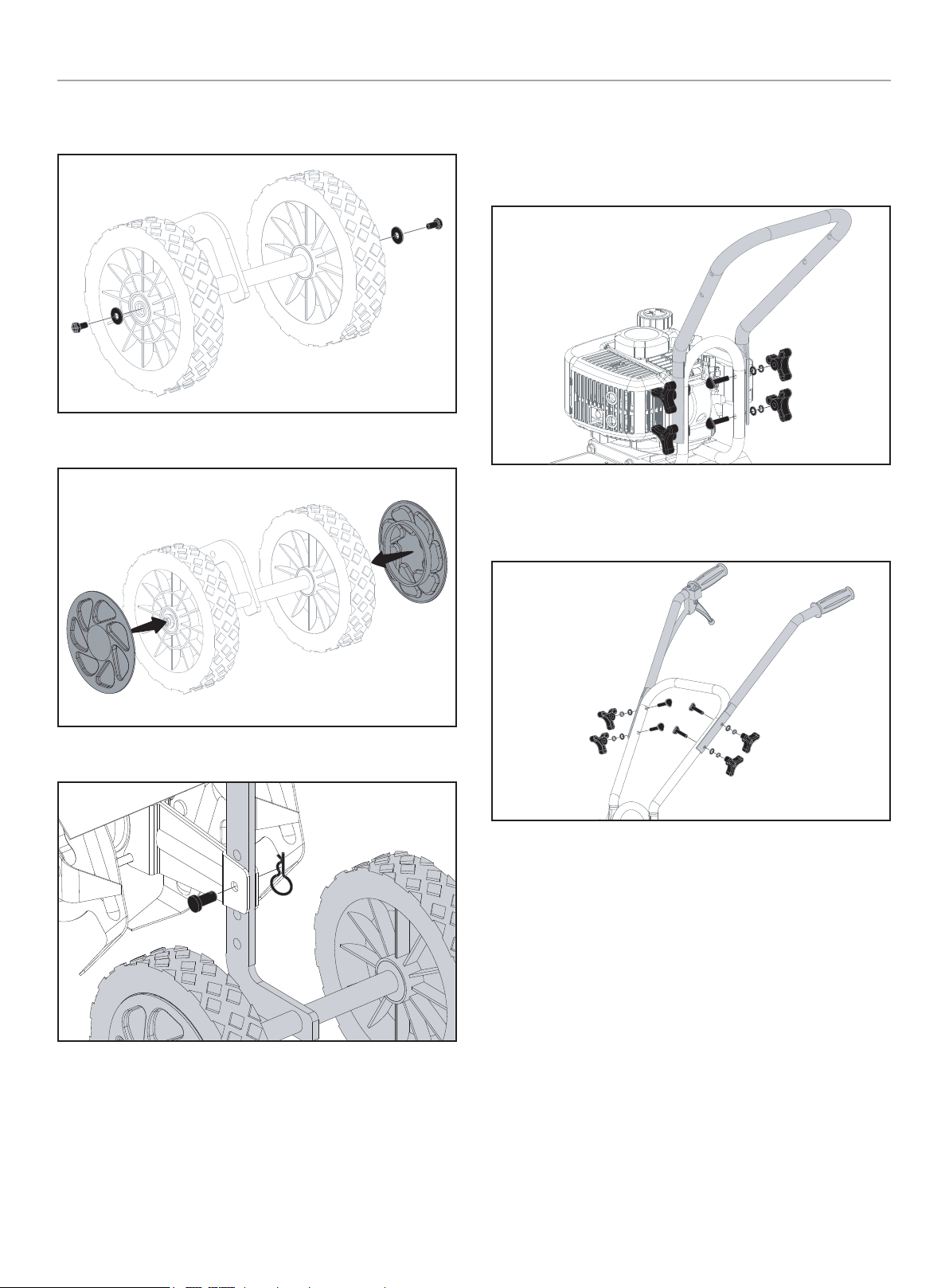
100882 - CULTIVATOR
ASSEMBLY
13
4. Slide a washer onto the axle on each side. Add the nut and
hand tighten.
5. Snap hubcap to outside of each wheel.
6. Attach wheel assembly to main body, reverse steps 1-2.
Handle Assembly
1. Attach the middle handle to the lower handle using the knob
nuts, lock washers, flat washers and curved head bolts
provided. The knob nuts should be on the outside.
2. Attach the left handle and right handle to the middle handle
using the knob nuts, lock washers, flat washers and curved
head bolts provided. The knob nuts should be on the outside.
Add Fuel
Your cultivator is powered by a two stroke engine which requires a
fuel mixture of gasoline and lubricating oil.
Recommended mixing ratio
Gasoline 50: Oil 1
Use a mixture of 50 parts unleaded regular gasoline and 1 part
two-stroke oil (50:1.) Use unleaded gasoline intended for motor
vehicle use with an octane rating of 87 or higher.Never use fuel
containing more than 10% ethanol.
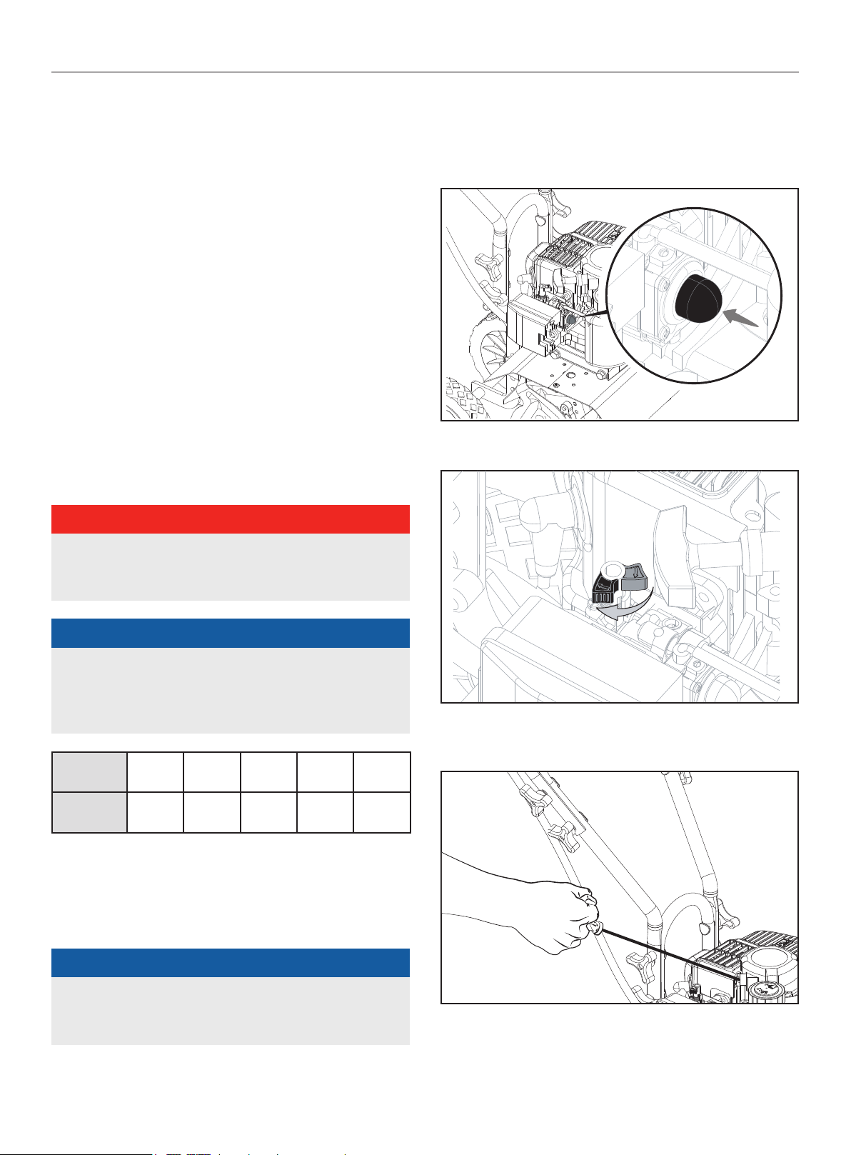
How to mix fuel
1. Pour 1 gal. (3.8 L) of the gasoline into a safe container. Do not
mix the fuel and oil in the engine fuel tank.
2. Add 2.6 oz (76 mL) of two-cycle engine oil to the gasoline.
Screw the cap on the fuel container and then swirl the
container slowly to blend the oil and gasoline.
100882 - CULTIVATOR
OPERATION
14
Fueling the unit
1. Carefully pour the fuel mix into the cultivator’s fuel tank.
2. Only fill the fuel tank to 80% of the full capacity.
3. Fasten the fuel cap securely and wipe up any fuel spillage
around the unit.
Important: Always re-mix two-cycle fuel before fueling your
cultivator. Never, run your cultivator on gasoline alone. This will
ruin your engine and void all warranties.
Always use a clean gasoline container and always use unleaded
gasoline with less than 10% ethanol.
Never try to mix the oil and gasoline in the engine fuel tank.
Always mix oil and gasoline in the proper proportions: 2.6 oz
(76 mL) of two-cycle engine oil to 1 gallon (3.8 L) of unleaded
gasoline.
Pre-mixed fuels like 50:1 TruFuel are also good options to fuel
your cultivator.
Ethanol – High levels of ethanol can cause deterioration of rubber
and/or plastic parts and disruption of engine lubrication. Never use
fuel containing more than 10% ethanol.
DANGER
Fuel is extremely flammable. Handle it with care. Keep away
from ignition sources. DO NOT smoke while fueling your
equipment.
NOTICE
DO NOT use old or stale oil/gasoline mixture older than 60
days. Always use the proper oil/gasoline mixture. Not following
these instructions will cause your engine to suffer rapid and
permanent damage, AND will void the engine warranty.
Gasoline
gal. (L)
1 gal.
(3.8 L)
2 gal.
(7.6 L)
3 gal.
(11.4 L)
4 gal.
(15.1 L)
5 gal.
(18.9 L)
2-Cycle Oil
gal. (ml)
2.6 oz.
(76 ml)
5.1 oz.
(152 ml)
7.7 oz.
(228 ml)
10.2 oz.
(302 ml)
12.9 oz
(378 ml)
OPERATION
Starting and Stopping
NOTICE
To avoid breaking the starter rope, do not pull the whole length or
let it slide along the edge of the rope guide. Allow the starter rope
to rewind gradually.
To Start a Cold Engine:
1. Cultivator should be on a flat, bare surface for starting.
2. Slowly press the primer bulb 7-10 times or until fuel is visible
and flows freely into the clear tank return line.
3. Set the choke lever to the CHOKE position
4. Holding the unit firmly, pull the starter handle until the engine
starts.
100882 - CULTIVATOR
OPERATION
15
5. Press the throttle trigger when the engine starts. This will
automatically move the choke lever to the RUN position. Once
the engine is running, release the throttle trigger.
NOTICE
Manually adjusting or turning the choke lever to the CHOKE
position during idle will cause the engine to stop.
NOTICE
Allow engine to warm at least 30 seconds depending on ambient
temperature. The colder the temperature, the longer the warm up
required.
To Start a Warm Engine:
1. Do not adjust the CHOKE lever. It should already be in the
RUN position. If not, press the throttle trigger once. This will
automatically move the choke lever back to the RUN position.
2. Holding the unit firmly, pull starter handle until engine starts.
Use short pulls and do not allow the rope to snap back.
NOTICE
If the engine does not start, return to the “Start a Cold Engine”
and repeat the steps that follow.
To Stop the Engine
To stop the engine, depress and hold the throttle switch to the
STOP position.
Special Feature (with Idle Set Properly and
the Engine Running).
Even when the engine is running, the tines won’t turn unless you
press the throttle lever on the handlebars. And, when you release
the throttle lever, the tines will stop.
Tips for Extending Engine Life
After you start the engine, let your cultivator warm up for two
to three minutes before you use it. Then, before you put your
cultivator away, let it idle for a minute to give the engine a chance
to cool down.
Gently shake mixed fuel before adding to the cultivator to ensure
proper oil content.
Only use fuel less than 60 days old.
WARNING
If the engine does not stop when the engine switch is moved
in the “STOP” position, release the throttle. Allow the engine
to idle.
Put the cultivator down and slide the choke lever to cold start
(closed) position.
Check and return engine switch to the “ON” position before
starting the engine again.
100882 - CULTIVATOR
OPERATION
16
Cultivating
Now You’re ready to Use Your Cultivator
If you’ve used a cultivator in the past you know that you walk
behind a cultivator as the soil is churned. Your Champion cultivator
may surprise you in the fact it works best if you pull it towards
you. It tills best when you pull it backward! You see, when you pull
your cultivator backward, it provides extra resistance to the tines,
so they dig deeper. What’s more when you go backward, you
create a soil bed that stays light and fluffy ready for plating.
Place your cultivator at the head of the row or area you want to
cultivate. Start it up. Then use an easy rocking motion to pull your
cultivator backward and then, let it move forward. Repeating this
motion while moving the cultivator left and right will maximize
the performance of the product and produce optimum planting
conditions by helping you cultivate deeper.
Keep repeating these steps until you’ve tilled an entire row. Start
again on the next row. It’s much like running a vacuum cleaner!
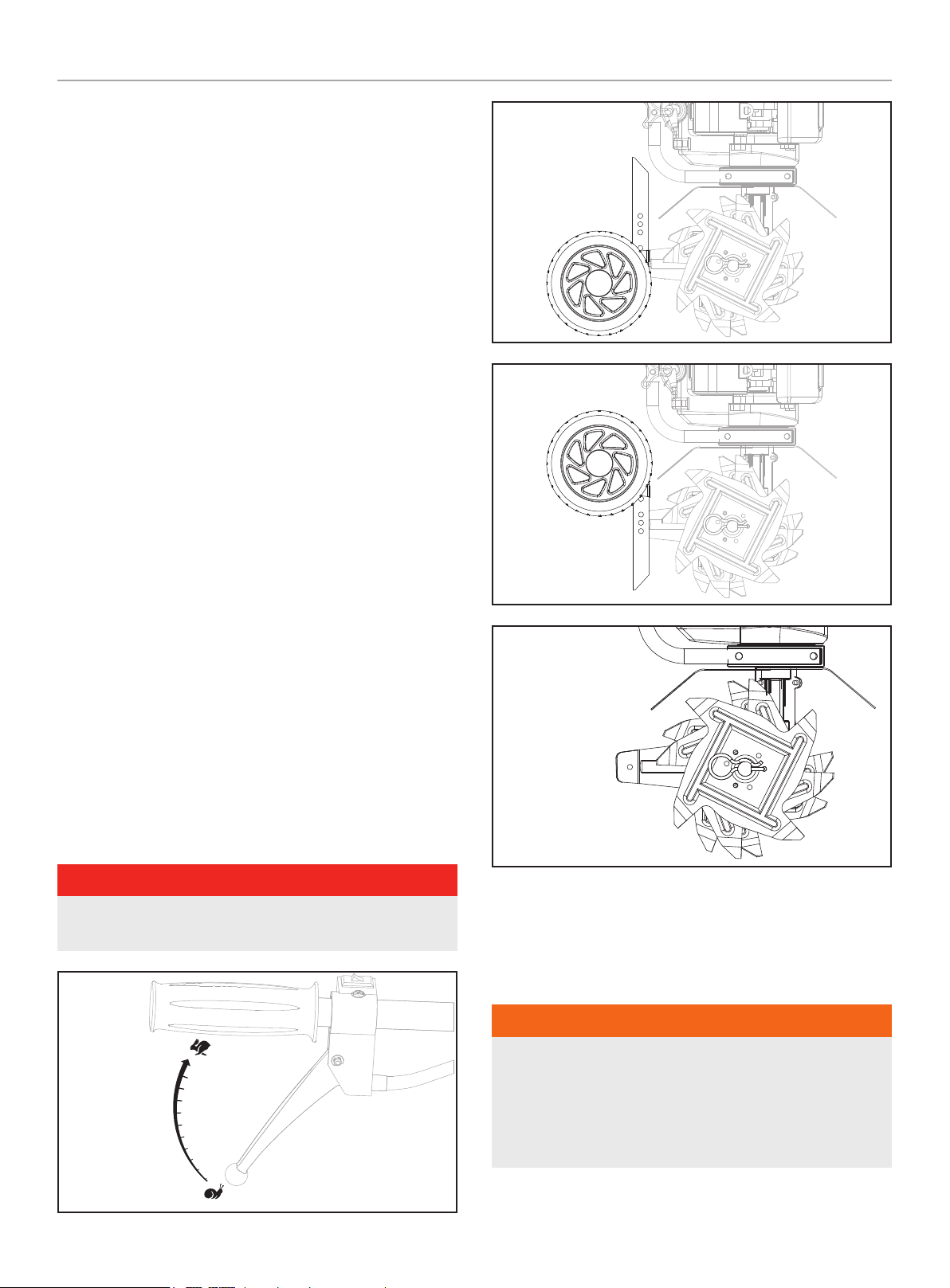
You Can Even Control Depth
For Deeper Cultivating:
– Move your cultivator slowly back and forth, as you would
a vacuum cleaner. Work the same area over and over until
you’ve dug to your desired depth.
– You can use your transport wheel / depth gauge assembly to
set specific working depth for your cultivator, see the diagram.
For Shallow Cultivating and Weeding:
– You can quickly skim over an area to weed or scarify the
ground for seeding. Simply move the cultivator quickly over
your soil surface back and forth, left and right allowing the
tines to float on the top of the ground.
For Big Weeds or Tough Roots:
– Let your cultivator rock back and forth over the tough spot,
until the tines slice through the weed or root.
DANGER
The operator of this cultivator is responsible for accidents or
hazards occurring to himself, other people or their property.
Transporting
position
Working
position
Working without wheels
or depth gauge
Remember, any cultivator will tangle in tall grass, stringy vines, or
overly large weeds. So, if you plan to cultivate in these conditions
first use a pruner or brush cutter to chop up the overgrowth. If the
tines become tangled, turn the engine off and allow the tines to
full come to a stop before trying to clear them.
WARNING
If your tines get jammed or entangled, shut off the engine at
once.
Remove the obstruction while the engine is off.
NEVER try to remove an obstruction while the engine is
running. SERIOUS INJURY CAN RESULT.
100882 - CULTIVATOR
MAINTENANCE
17
MAINTENANCE
WARNING
Never operate a damaged or defective cultivator.
WARNING
Improper maintenance will void your warranty.
NOTICE
For Emission control devices and systems, read and
understand your responsibilities for service as stated in the
Emission Control Warranty Statement of this manual.
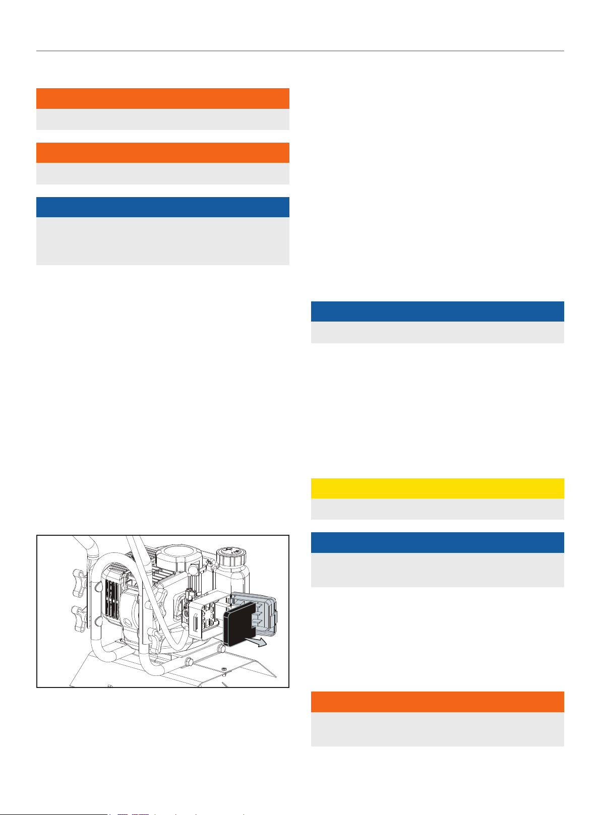
How to Check, Clean and Change the Air
Filter
Check the air filter every 25 hours of use or more frequently if
used under dusty conditions. A clogged air filter may increase fuel
consumption while cutting down the engine power. Never operate
the cultivator without the air filter or with a deformed filter element
because unfiltered dust will damage the engine.
Cleaning Air Filter
1. Remove the air cleaner cover by pulling the tab on side and
take out the filter element.
2. Use mild detergent and warm water to clean the filter
element. After cleaning, air dry the element completely and
moisten with a small amount of motor oil.
3. Place the filter element into the air cleaner housing and press
the cover against the housing until it clicks.
Idle Speed Adjustment
1. Warm up engine before adjusting idle speed.
2. The idle speed adjustment screw controls the throttle opening
at idle position.
3. When the engine tends to stop frequently at idling mode, turn
the adjusting screw clock wise.
4. If the tines continue to rotate after releasing the trigger, turn
the adjusting screw counter-clockwise.
Clear Blockages From the Fuel Line & Filter
1. After you’ve used your cultivator for a few seasons, check for
blockages in the fuel tank and fuel filter. Such blockages can
keep your cultivator from starting and running properly.
2. Clear any blockages you see in the tank or fuel line, replace
the fuel filter if needed.
NOTICE
The fuel filter is located inside the tank.
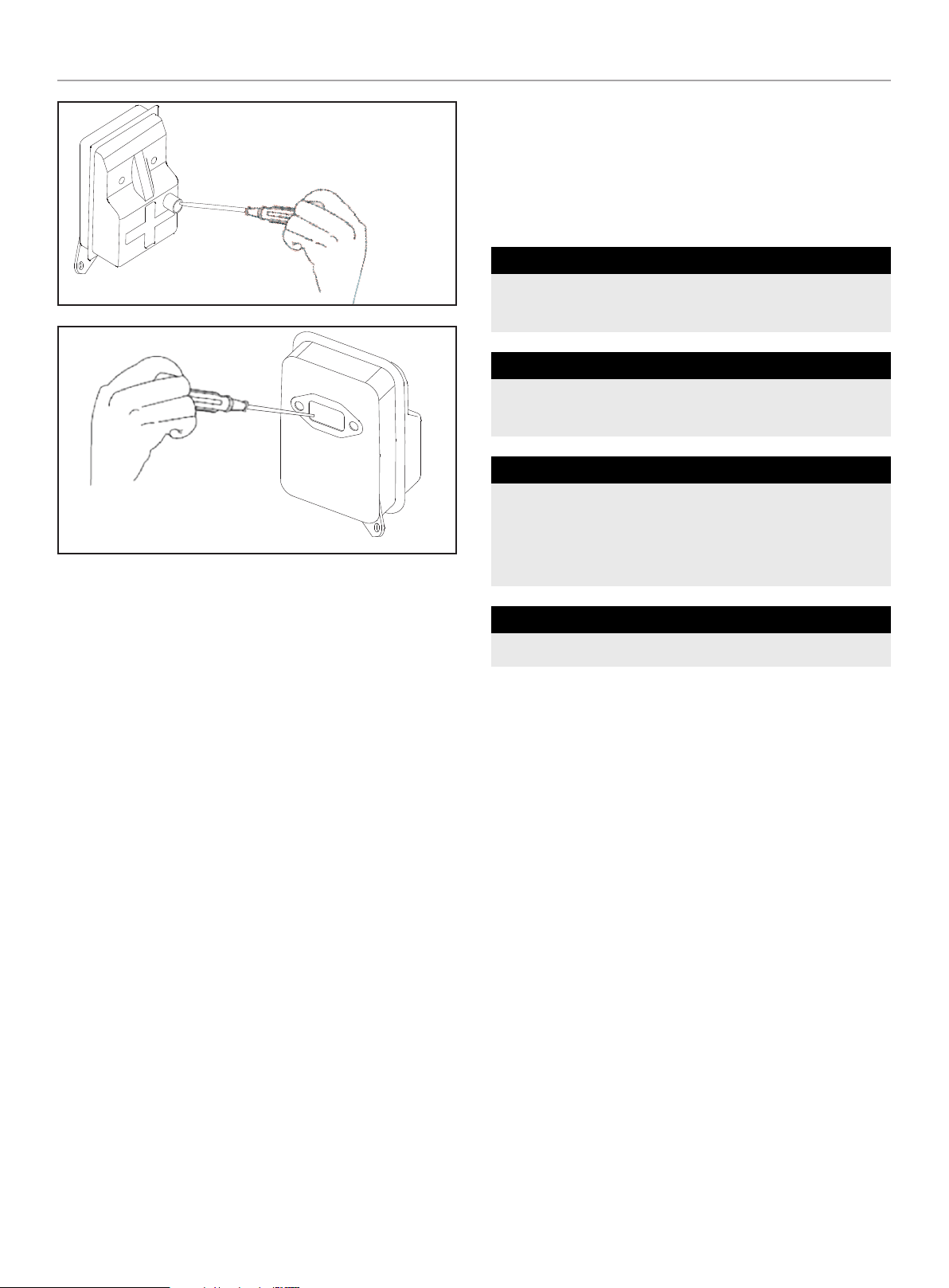
Spark Plug
Starting failure and mis-firing are often caused by a fouled spark
plug. Clean the spark plug and adjust the plug gap to
0.020-0.028 in. (0.5-0.7 mm) if necessary.
– To install the spark plug first turn the plug until it is finger
tight, then tighten it a quarter turn more with a ¾ in. (19 mm)
socket wrench.
CAUTION
DO NOT overtighten the spark plug.
NOTICE
The cultivator uses NHSP L8RTC or NGK BPMR7A spark plug.
Use an exact replacement and replace annually.
Muffler
Inspect periodically the muffler for loose fasteners, any damage
or corrosion or blockage caused by insect nests. If any sign of
exhaust leakage is found, stop using the machine and have it
repaired immediately.
WARNING
Note that failing to do so may result in the engine catching on
fire.
100882 - CULTIVATOR
MAINTENANCE
18
Intake Air Cooling Vent
– Never touch the cylinder, muffler, or spark plugs with your bare
hands immediately after stopping the engine. The engine can
become very hot when in operation, and doing so could result
in severe burns.
– When checking the machine before using it, check the area
around the muffler and remove any debris. Failing to do so
could cause the muffler to become overheated, and that this in
turn could cause the engine to catch on fire. Always make sure
that the muffler is clean and free of debris before use.
– Check the intake air cooling vent and the area around the
cylinder cooling fins after every 25 hours of use for blockage.
Note that it is necessary to remove the engine cover in order to
view the upper part of the cylinder.
Procedures to be Performed After Every 100
Hours of Use
– Remove the muffler, insert a screwdriver into the vent, and
wipe away any carbon buildup. Wipe away any carbon buildup
on the muffler exhaust vent and cylinder exhaust port at the
same time.
– Tighten all screws, bolts, and fittings.
– Check to see if any oil or grease has worked its way in
between the clutch lining and drum, and if it has, wipe it away
using oil-free, lead-free gasoline.
Maintenance Schedule
Follow the service intervals indicated in the schedule below.
Service your cultivator more frequently when operating in adverse
conditions. Contact our help line at 1-877-338-0999 to locate the
nearest Champion Power Equipment authorized service dealer for
your cultivator or engine maintenance needs.
BEFORE USE
Wipe out fuel leaks, fuel spillage.
Inspect and clean fuel tank, air filter and fuel filter.
EVERY 25 HOURS
Clean cylinder fins and intake air cooling vent.
Clean air filter.
EVERY 50 HOURS
Clean and readjust spark plug gap
(gap: 0.020-0.028 in. (0.5-0.7 mm) replace if necessary).
Clean exhaust port.
Clean air filter.
ANNUALLY
Replace spark plug.
* Time intervals shown are maximum. Actual use and your experience will
determine the frequency of required maintenance.

100882 - CULTIVATOR
STORAGE
19
STORAGE
Cultivator Storage
Each fall — or before you store your cultivator for any long
period — be sure to take these measures:
1. Do not store fuel in your cultivator for long periods of time.
Even under ideal conditions, stored fuel containing ethanol
can begin to stale in as little as 60 days. Since stale fuel has
a high gum content, it can clog the carburetor, this will in
turn restrict fuel flow. When ready to store your cultivator, or
will not be using it for more than 2 weeks, drain the fuel tank
completely.
NOTICE
You can store the unit with 50:1 TruFuel because it is pretreated
with stabilizer and has NO ethanol content.
2. Remove fuel from the carburetor and fuel lines by starting
the engine and letting the cultivator run out of fuel. This will
prevent gum deposits forming inside of the carburetor and
possible engine damage.
3. Disconnect spark plug wire and remove the spark plug (use
a ¾ in. {19 mm} spark-plug wrench). Pour about a teaspoon
of clean, air-cooled, two cycle oil through the spark-plug hole
into the combustion chamber. Slowly pull the starter cord two
or three times to coat the inside of the cylinder wall.
4. Inspect the spark plug, and, if necessary, clean it. The
cultivator uses NHSP L8RTC or NGK BPMR7A spark plug. Use
an exact replacement and replace annually.
5. Install the spark plug, but leave the spark plug wire
disconnected.
6. Clean the air filter as described on page 14.
7. Clean dirt, grass, and other materials from the entire
machine.
8. Wipe the tines with oil or spray them with a rust inhibitor such
as WD-40.
9. Oil the throttle cable and all visible moving parts. (Do not
remove the engine cover.)
10. Store your cultivator — in an upright position — in a clean,
dry place.
11. Do you have fuel left over from last season? Dispose of it
properly. Buy fresh oil and gasoline next season.
How to Prepare Your Cultivator for Restarting
In the Spring, when you take your cultivator out of storage, remove
the spark plug. Pull the starter cord three or four times to clean oil
from the combustion chamber. Wipe oil from the spark plug. Place
the spark plug back into the cylinder. Reconnect the spark plug
wire back on the spark plug. Then follow the steps to refuel and
restart your cultivator.
Re-Starting Problems After Storage
If your cultivator won’t restart in the Spring - or if it lacks its usual
power - the carburetor may need attention or the spark plug
may be at fault. Check to see if the plug is fouled with oily black
deposits. Clean or replace it if it is.
Also, check whether the center electrode is rounded at the end,
or if the ground electrode is worn. If either is the case, you should
replace it with a NHSP L8RTC or NGK BPMR7A spark plug. Use a
¾ in. {19 mm} spark-plug wrench to install it. Adjust the plug gap
to 0.020-0.028 in. (0.5-0.7 mm). To install the spark plug first turn
the plug until it is finger tight, then tighten it a quarter turn more
with a ¾ in. {19 mm} socket wrench.
NOTICE
To avoid possible damage to the threads, do not try to remove the
plug from a hot aluminum cylinder head.

100882 - CULTIVATOR
SPECIFICATIONS
20
SPECIFICATIONS
Cultivator Specifications
Start Type
.................................................... Recoil
Gasoline/Oil Ratio .............................................. 50:1
Fuel Capacity ........................................ 0.3 gal. (1.1 L)
Weight ............................................ 33.5 lb. (15.2 kg)
Length ............................................. 38.6 in. (98 cm)
Width ............................................... 17.7 in. (45 cm)
Height ...............................................35.4 in. (90 cm)
Engine Specifications
Model ..................................................... 1E40F-2E
Displacement .................................................. 43 cc
Type ........................................................ 2-Stroke
Spark Plug
OEM Type ............................................ TORCH L8RTC
Replacement Type ..................... NGK BPMR7A or equivalent
Gap ................................. 0.020-0.028 in. (0.5-0.7 mm)
100882 - CULTIVATOR
CONTROLS AND FEATURES
21
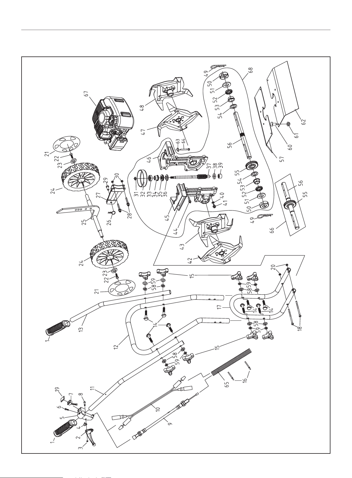
Parts Diagram

100882 - CULTIVATOR
CONTROLS AND FEATURES
22
# Part Number Description Qty.
1 2320091377
Cover, Handle
2
2 2320091338 Throttle Lever 1
3 2320090975 Circlip Ø3.5 1
4 2320104231 Torsional spring 1
5 2320091337 Throttle Bracket 1
6 2310003906 Screw ST4.8 x 19 1
7 2320123806 Switch Assembly 1
8 2320104230 Pin 1
9 2320106894 Throttle Cable Assembly 1
10 2320090287 Connector Wire 1
11 2320090565 Right Handle 1
12 2320090564 Middle Handle 1
13 2320090561 Left Handle 1
14 2320090988
Curved-Head Bolt
M8 x 45
8
15 2320091339 Knob nut M8 8
16 2310001734 Tie Strap 5
17 2320090563 Lower Handle 1
18 2310003907 Bolt M8 x 150 2
19 2320059838 Switch Cover 1
20 2310003908 Lock Nut M8, Flange 2
21 2320121537 Wheel Cup 2
22 2310003909 Bolt M6 x 12 2
23 2310003910 Washer Ø6 2
24 2320090292 Wheel Assembly 2
25 2320106908 Axle Assembly 1
26 2320090995 R clip Ø3 1
27 2320090568 Bracket Assembly 1
28 2310004441 Bolt M6 x 35 2
29 2320106895 Clevis Pin 8 x 18 1
30 2310003920 Lock Nut M6, Flange 2
31 2310004158 Nut M8 1
32 2320106207 Clutch Drum 1
33 2310003937 Roller Bearing 629-2RS 1
34 2320088857
Flange Bushing,
Worm Shaft
1
35 2310004438
Needle Roller Thrust
Bearing
1
36 2320093333 Bearing Thrust Reducer 1
37 2320111467 Worm Shaft 1
38 2320098053 Washer 1
39 2310004157
Drawn Cup Needle Roller
Bearing
1
40 2320055620 Seal Washer 2
# Part Number Description Qty.
41 2310004160 Bolt M6 x 10 2
42 2320106902 Tine D Assembly 1
43 2320106901 Tine C Assembly 1
44 2310004442 Bolt M6 x 20 6
45 10304101 Left Gear Housing 1
46 10304100 Right Gear Housing 1
47 2320106900 Tine B Assembly 1
48 2320106898 Tine A Assembly 1
49 2320106903 R clip 2
50 2320104924 Dust Cap 2
51 2320088862 Fiber Washer 2
52 2310003849 Seal FB19 x 32 x 6.5 2
53 2320088861
Flange Bushing,
Tine Shaft
2
54 2320088860 Washer 2 2
55 2320088866 Worm 1
56 2320103366 Tine Shaft 1
57 2320121538 Fender Guard 1, Yellow 1
58 2310000769 Flat Washer Ø8 8
59 2310003916 Lock Washer Ø8 8
60 2310004876
Bolt M5 x 16
GB / T9074.13
2
61 2310004025 Lock Nut M5 2
62 2320121539 Fender Guard 2, Yellow 1
63 2310000106 Lock Washer Ø6 4
64 2310003912 Bolt M6 x 40 4
65 2320092108
Housing, Throttle
Cable&Connector Wire
1
66 19002144 Combined Shaft 1
67 80308228 Engine 1
68 19002085 Transmission Assembly 1
Parts List
100882 - CULTIVATOR
CONTROLS AND FEATURES
23
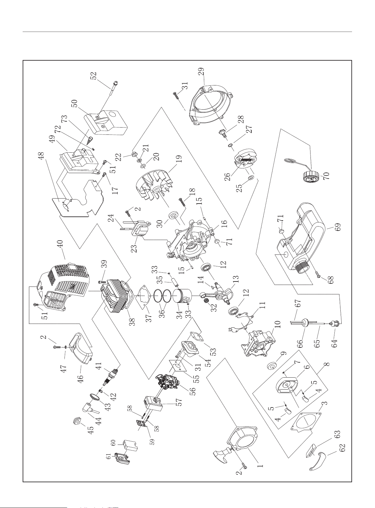
Engine Parts Diagram

100882 - CULTIVATOR
CONTROLS AND FEATURES
24
# Part Number Description Qty.
1 2320106891
Starter Assembly
1
2 2310003892 Screw M5 x 20 7
3 2320008967 Gasket, Starter 1
4 2320034480 Start Claw 2
5 2320039918 Start Spring 2
6 2320039919 Start Reel 1
7 2310000177 Stop Ring 4 2
8 2320060040 Start Reel Assembly 1
9 2320088343 Oil seal 1
10 10302749 Crankcase, Rear 1
11 2320059733 Gasket, Crankcase 1
12 2310002694 Bearing 6202/P6 2
13 10200889
Crankshaft/Connecting
Rod Assembly
1
14 2310000056 Key 3 x 5 x 13 1
15 2310000935 Pin 4h8 x 10 4
16 10302746 Crankcase, Front 1
17 2310003901 Screw M4 x 12 1
18 2310003904 Screw M5 x 30 4
19 2320106878 Fan, Engine 1
20 2310000769 Washer Ø8 1
21 2310003896 Lock Washer Ø8 1
22 2310003895 Nut M8 1
23 2320106879 Ignition Coil Component 1
24 2320073280 Cord Component 1
25 2320008369 Flat Washer B 2
26 2320065833 Expander 1
27 2320049788 Wave Spring Washer 2
28 2320028659 Screw Pin 2
29 10302822 Fan Cover 1
30 2320001284 Oil seal 1
31 2310003893 Screw M5 x 25 6
32 2320029199 Bearing, Connecting Rod 1
33 2320027110 Circlip, Piston Pin 2
34 2320050831 Piston 1
35 2320008661 Piston Pin 1
36 2320048282 Piston Ring Assembly 2
37 2320050467 Gasket, Cylinder 1
38 10301805 Cylinder 1
39 2310003898 Screw M5 x 20 4
40 2320121536 Guide Cover Assembly 1
41 2320007046 Spark Plug, L8RTC 1
42 2320007063 Spring, Spark Plug 1
# Part Number Description Qty.
43 2320106881 Spark Plug Cap 1
44 2320106870 Cap 1
45 2320094566 Plug 1
46 2320090288 Top Cover 1
47 2320028123 Insulation Gasket 1
48 2320106496 Gasket, Muffler 1
49 2320127219 Muffler Assembly 1
50 2320036825 Cover, Muffler 1
51 2310003894 Screw M5 x 12 2
52 2310003888 Screw M6 x 60-12.9 2
53 2320008715 Gasket, Admitting Pipe 1
54 2320056326 Admitting Pipe 1
55 2320008636 Gasket, Carburetor 1
56 2320121674 Carburetor Assembly 1
57 2320106893 Air Cleaner Housing 1
58 2310003903 Screw M5 x 50 2
59 2320090969 Plate, Filter 1
60 2320086676 Filter 1
61 2320100673 Air Cleaner Cover 1
62 2320016552 Stand, Fuel Tank 1
63 2320003287 Rubber Cover 1
64 2320047780 Fuel Filter 1
65 2320121534 Fuel Inlet Pipe 1
66 2320091481 Seal Plug 1
67 2320121535 Fuel Return Pipe 1
68 2310003900 Screw M5 x 16 2
69 2320091479 Fuel Tank 1
70 2320091480 Fuel Tank Cap Assembly 1
71 2320090299 Rubber washer 2
72 2310005007 Screw M3 x 8 1
73 2320127218 Spark Arrester 1
Engine Parts List

100882 - CULTIVATOR
TROUBLESHOOTING
25
TROUBLESHOOTING
If you follow the normal starting procedure, you should have no
problem starting your cultivator. But, just in case you do have
problems, here’s what to do:
– Make sure the engine switch is in the “ON” position. If the
switch was in the “STOP” position when you pulled the cord,
you may have flooded the engine. Even if the engine switch
is in the “ON” position, it is possible to flood the engine. The
smell of fuel can be a sign the engine is flooded.
1. Flooded Engine Procedure:
1a. First, examine the spark plug. Use a 19 mm spark plug
wrench.
1b. Remove the cap over the spark plug.
IMPORTANT: To avoid possible damage to the threads, do not
try to remove the plug from a hot engine.
1c. Unscrew the spark plug.
1d. If the end of the spark plug is wet, the engine may be
flooded. Make sure the switch is in the “Stop” position,
disconnect spark plug wire and remove plug. Use a paper
towel or a clean rag to dry the spark plug, then, with the
spark plug out of the engine, pull the starter cord several
times. Shake the fuel out of the inside of the plug and
air dry. Next, replace the spark plug. Use the wrench to
tighten it and replace the cap. Next, put the switch in the
“Start” position and pull the choke lever into the “Start”
position. Pull the starter cord three or four times until the
engine coughs or sputters. Open the choke (move the
choke lever to the “Run” position) and pull the cord a few
times. The engine should start and run.
If the end of the spark plug is dry, check to see if the fuel line
is blocked.
– The fuel line runs from the fuel tank to the carburetor. Pull it
off at the carburetor end. Fuel should drip slowly from the line.
Wipe off any excess or spilled fuel.
– If fuel does not drip from the line, check the line for any bends
or pinches. Kinks in the line restrict the flow of fuel to the
engine. Just straighten out the line. Reconnect. Then follow
the normal starting procedure.
– If fuel drips too freely, the line may be disconnected from the
fuel filter. You’ll find the fuel filter inside the fuel tank. Just re-
attach the line to the filter, and put the filter back in the tank.
Then follow the normal starting procedure.
WARNING
Make sure the engine switch is in the top position. Keep plug
wire away from engine to avoid unintentional spark.
IMPORTANT: Never use starting fluids. Starting fluids will
cause permanent engine damage. Using them will void the
warranty.
Problem Check Cause Solution
Starting Failure
Fuel tank Incorrect fuel Drain and fill with correct fuel
Fuel filter Fuel filter is clogged Replace fuel filter
Flooded engine Multiple
Let unit sit to air out (15 minutes)
or remove spark plug and clean per
instruction in manual
Sparking (no spark)
Spark plug is fouled/ wet, plug
gap is incorrect
Clean/ dry, correct gap:
0.020-0.028 in. (0.5-0.7 mm)
Engine starts but does not keep
running/ hard re-starting
Fuel Tank Incorrect fuel Drain and fill with correct fuel
Muffler, cylinder
(exhaust port)
Carbon is built-up or insect nest
in exhaust port
Wipe away and or clean out
Air cleaner Clogged with dust
Wash with mild detergent and water,
dry thoroughly
For other issues and technical support:
Technical Support Team
Mon-Fri 8:30 AM-5:00 PM (PST/PDT)
Toll Free 1-877-338-0999
support@championpowerequipment.com

WARRANTY*
CHAMPION POWER EQUIPMENT
2 YEAR LIMITED WARRANTY
Warranty Qualifications
To register your product for warranty and FREE lifetime call center
technical support please visit:
https://www.championpowerequipment.com/register
To complete registration you will need to include a copy of the
purchase receipt as proof of original purchase. Proof of purchase
is required for warranty service. Please register within ten (10)
days from date of purchase.
Repair/Replacement Warranty
CPE warrants to the original purchaser that the mechanical and
electrical components will be free of defects in material and
workmanship for a period of two years (parts and labor) from
the original date of purchase and 180 days (parts and labor) for
commercial and industrial use. Transportation charges on product
submitted for repair or replacement under this warranty are the
sole responsibility of the purchaser. This warranty only applies to
the original purchaser and is not transferable.
Do Not Return The Unit To The Place Of
Purchase
Contact CPE’s Technical Service and CPE will troubleshoot any
issue via phone or e-mail. If the problem is not corrected by
this method, CPE will, at its option, authorize evaluation, repair
or replacement of the defective part or component at a CPE
Service Center. CPE will provide you with a case number for
warranty service. Please keep it for future reference. Repairs or
replacements without prior authorization, or at an unauthorized
repair facility, will not be covered by this warranty.
Warranty Exclusions
This warranty does not cover the following:
Normal Wear
Products with mechanical and electrical components need
periodic parts and service to perform well. This warranty does not
cover repair when normal use has exhausted the life of a part or
the equipment as a whole.
Installation, Use and Maintenance
This warranty will not apply to parts and/or labor if the product is
deemed to have been misused, neglected, involved in an accident,
abused, loaded beyond the product’s limits or modified. Normal
maintenance is not covered by this warranty and is not required to
be performed at a facility or by a person authorized by CPE.
Other Exclusions
This warranty excludes:
– Cosmetic defects such as paint, decals, etc.
– Wear items such as filter elements, o-rings, etc.
– Failures due to acts of God and other force majeure events
beyond the manufacturer’s control.
– Problems caused by parts that are not original Champion
Power Equipment parts.
Limits of Implied Warranty and
Consequential Damage
Champion Power Equipment disclaims any obligation to cover
any loss of time, use of this product, freight, or any incidental
or consequential claim by anyone from using this product.
THIS WARRANTY AND THE ATTACHED U.S. EPA and/or CARB
EMISSION CONTROL SYSTEM WARRANTIES (WHEN APPLICABLE)
ARE IN LIEU OF ALL OTHER WARRANTIES, EXPRESS OR IMPLIED,
INCLUDING WARRANTIES OF MERCHANTABILITY OR FITNESS
FOR A PARTICULAR PURPOSE.
A unit provided as an exchange will be subject to the warranty
of the original unit. The length of the warranty governing the
exchanged unit will remain calculated by reference to the purchase
date of the original unit.
This warranty gives you certain legal rights which may change
from state to state or province to province. Your state or province
may also have other rights you may be entitled to that are not
listed within this warranty.
Contact Information
Address
Champion Power Equipment, Inc.
12039 Smith Ave.
Santa Fe Springs, CA 90670 USA
www.championpowerequipment.com
Customer Service
Toll Free: 1-877-338-0999
info@championpowerequipment.com
Fax no.: 1-562-236-9429
Technical Service
Toll Free: 1-877-338-0999
tech@championpowerequipment.com
EMERGENCY 24 HOUR SUPPORT: 1-562-204-1188
*Except as otherwise stipulated in any of the following enclosed Emission Control System Warranties (when applicable) for the Emission Control System: U.S. Environment Protection Agency
(EPA) and/or California Air Resources Board (CARB).

CHAMPION POWER EQUIPMENT, INC. (CPE) AND
THE UNITED STATES ENVIRONMENTAL PROTECTION AGENCY (U.S. EPA)
EMISSION CONTROL SYSTEM WARRANTY
Your Champion Power Equipment (CPE) engine complies with U.S. EPA emissions regulations.
YOUR WARRANTY RIGHTS AND OBLIGATIONS:
The U.S. EPA and CPE are pleased to explain the Federal Emission Control System’s Warranty on your 2021 small off-road engine and
engine powered equipment. In the United States new equipment that use small off-road engines shall be designed, built and equipped to
meet U.S. EPA regulations. CPE shall warrant the emission control system on your small off-road engine and equipment for the period of
listed below, provided there has been no abuse, neglect, unapproved modification or improper maintenance of your equipment.
Your emission control system may include parts such as: carburetor, fuel tanks, fuel lines (for liquid fuel and fuel vapors), fuel caps, valves,
canisters, filters, clamps, connectors, and other associated components. Where a warrantable condition exits, CPE will repair your small
off-road engine at no cost to you including diagnosis, parts and labor.
MANUFACTURER’S WARRANTY COVERAGE:
This emission control system is warranted for two years. If any emission related part on your engine or equipment is defective, the part will
be repaired or replaced by CPE.
OWNER’S WARRANTY RESPONSIBILITIES:
As the small off-road engine owner, you are responsible for the performance of the required maintenance listed in your Owner’s Manual.
CPE recommends that you retain all your receipts covering maintenance on your small off-road engine, but CPE cannot deny warranty
solely for the lack of receipts.
As the small off-road engine owner, you should be aware that CPE may deny you warranty coverage if your small off-road engine or a part
has failed due to abuse, neglect, or improper maintenance or unapproved modifications.
You are responsible for presenting your small off-road engine to an Authorized CPE distribution center or service center or alternate service
outlet as soon as a problem exists. The warranty repairs shall be completed in a reasonable amount of time, not to exceed 30 days.
If you have any questions regarding your warranty coverage, you should contact:
Champion Power Equipment, Inc.
Customer Service
12039 Smith Ave.
Santa Fe Springs, CA 90670
1-877-338-0999
tech@championpowerequipment.com

EMISSION CONTROL SYSTEM WARRANTY
1. APPLICABILITY: This section applies to Emissions Control Systems on small off-road engines or equipment that use small off-road
engines subject to the emission standards in this Article. The warranty period begins on the date the new engine or equipment is
delivered to an ultimate purchaser and shall continue for 24 consecutive months thereafter.
2. GENERAL EMISSIONS WARRANTY COVERAGE
CPE warrants to the ultimate purchaser of the new engine or equipment and to each subsequent owner that the Emissions Control
System when installed is:
2a. Designed, built and equipped to conform to U.S. EPA emissions standards for spark-ignited engines at or below 19 kilowatts;
2b. Free from defects in materials and workmanship that cause the failure of a warranted part to be identical in all material respects
to the part as described in the engine manufacturer’s application for certification for a period of two years.
3. THE WARRANTY ON EXHAUST AND EVAPORATIVE EMISSION-RELATED PARTS WILL BE INTERPRETED AS FOLLOWS:
3a. Any warranted part that is not scheduled for replacement as required maintenance in the Operators Manual required by subsection
(e) must be warranted for the warranty period defined in subsection (b)(2). If any such part fails during the period of warranty
coverage, it must be repaired or replaced by CPE according to subsection (3)(3d) below. Any such part repaired or replaced under
the warranty must be warranted for a time not less than the any remaining warranty period.
3b. Any warranted emissions-related part that is scheduled only for regular inspection in the Operators Manual shall be warranted
for the warranty period defined in subsection (b)(2). A statement in such written instructions to the effect of “repair or replace as
necessary” shall advise owners of the warranty coverage for emissions related parts. Replacement within the warranty period is
covered by the warranty and will not reduce the period of warranty coverage. Any such emission-related part repaired replaced
under warranty shall be warranted for a time not less than the remaining warranty period.
3c. Any warranted emissions-related part that is scheduled for replacement as required maintenance in the Operators Manual shall
be warranted for the period of time prior to the first scheduled replacement point for that part. If the part fails prior to the first
scheduled replacement, the part shall be repaired or replaced by CPE according to Subsection (3)(3d) below. Any such emissions-
related part repaired or replaced under warranty shall be warranted for a time not less than the remainder of the period prior to
the first scheduled replacement point for such emissions-related part.
3d. Repair or replacement of any warranted emissions-related part under the Warranty provisions of this article shall be performed at
no charge to the owner at a CPE Authorized Service Outlet.
3e. The owner of the small off-road engine shall not be charged for diagnostic labor that leads to the determination that a warranted
part is in fact defective, provided that such diagnostic work is performed at a CPE Authorized Service Outlet.
3f. CPE shall pay for covered emissions warranty repairs at non-authorized service outlets under the following circumstances:
i. The service is required in a population center with a population over 100,000 according to U.S. Census 2000 without a CPE
Authorized Service Outlet AND
ii. The service is required more than 100 miles from a CPE Authorized Service Outlet. The 100-mile limitation does not apply in the
following states: Alaska, Arizona, Colorado, Hawaii, Idaho, Montana, Nebraska, Nevada, New Mexico, Oregon, Texas, Utah and
Wyoming.
3g. CPE shall be liable for damages to other original engine components or approved modifications proximately caused by a failure
under warranty of an emission-related part covered by the ECS Warranty.
3h. Throughout the Emissions Control Systems Warranty period, CPE shall maintain a supply of warranted emission-related parts
sufficient to meet the expected demand for such emission-related parts.
3i. Any CPE Authorized, and approved emission-related replacement part may be used in the performance of any ECS Warranty
maintenance or repair and will be provided without charge to the owner. Such use shall not reduce CPE’s warranty obligation.
3j. Unapproved add-on or modified parts may not be used to modify or repair a CPE engine. Such use voids this Warranty and shall
be grounds for disallowing a warranty claim. CPE shall not be liable hereunder for failures of any warranted parts of a CPE engine
caused by the use of such an unapproved add-on or modified part.

EMISSION-RELATED PARTS INCLUDE THE FOLLOWING: (using those portions of the list applicable to the
engine)
Systems covered by this
warranty
Parts Description
Fuel Metering System Fuel regulator, Carburetor and internal parts
Air Induction System Air cleaner, Intake manifold
Ignition System Spark plug and parts, Magneto ignition system
Exhaust System Exhaust manifold, catalytic converter
Miscellaneous Parts Tubing, Fittings, Seals, Gaskets, and Clamps associated with these listed systems.
Evaporative Emissions Fuel Tank, Fuel Cap, Fuel Lines (for liquid fuel and fuel vapors), Fuel Line Fittings, Clamps, Pressure
Relief Valves, Control Valves, Control Solenoids, Electronic Controls, Vacuum Control Diaphragms,
Control Cables, Control Linkages, Purge Valves, Gaskets, Liquid/Vapor Separator, Carbon Canister,
Canister Mounting Brackets, Carburetor Purge Port Connector
TO OBTAIN WARRANTY SERVICE:
You must take your CPE engine or the product on which it is installed, along with your warranty registration card or other proof of original
purchase date, at your expense, to any Champion Power Equipment dealer who is authorized by Champion Power Equipment, Inc. to sell
and service that CPE product during normal business hours. Alternate service locations defined in Section (3)(f.) above must be approved
by CPE prior to service. Claims for repair or adjustment found to be caused solely by defects in material or workmanship will not be denied
because the engine was not properly maintained and used.
If you have any questions regarding your warranty rights and responsibilities, or to obtain warranty service, please write or call
Customer Service at Champion Power Equipment, Inc.
Champion Power Equipment, Inc.
12039 Smith Ave.
Santa Fe Springs, CA 90670
1-877-338-0999
Attn.: Customer Service
tech@championpowerequipment.com