852372M-3605K
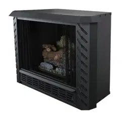
Certied for installations in the USA
Approved for installation in mobile homes
MAY BE INSTALLED IN A SOLID FUEL BURNING FIREPLACE, AS A FREESTANDING FIREPLACE, AS A ZERO
CLEARANCE FIREPLACE OR WITH AN OPTIONAL WOODEN SURROUND
* All Pictures In This Manual Are For Illustrative Purposes Only. Actual Product May Vary.
© 2020 United States Stove Company, 227 Industrial Park Rd., South Pittsburg, TN 37380 Ph. 800-750-2723
THIS MANUAL IS SUBJECT TO CHANGE WITHOUT NOTICE.
Owner’s Instruction and Operation Manual
Save These Instructions In A Safe Place For Future Reference.
CALIFORNIA PROPOSITION 65 WARNING:
This product can expose you to chemicals including carbon
monoxide, which is known to the State of California to cause
cancer, birth defects, and/or other reproductive harm. For
more information, go to www.P65warnings.ca.gov
INSTALLER: Leave this manual with the appliance.
CONSUMER: Retain this manual for future reference.
Please read this manual BEFORE
installing and operating this unit.
Do not store or use gasoline or other ammable vapors and liquids in the vicinity of this or any other appliance.
WHAT TO DO IF YOU SMELL GAS:
• Do not try to light any appliance.
• Do not touch any electrical switch; do not use any phone in your building.
• Leave the building immediately.
• Immediately call your gas supplier from a neighbor’s phone. Follow the gas supplier’s instructions.
• If you cannot reach your gas supplier, call the re department.
Installation and service must be performed by a qualied installer, service agency or the gas supplier.
WARNING:
FIRE OR EXPLOSION HAZARD
Failure to follow safety warnings exactly could result in serious injury, death, or property damage.
AGVF340
Report Number: 21-721
Model Number:
2
© 2020 United States Stove Company
CERTIFICATIONS
Note: Register your product online at
www.usstove.com or download the
free app today. This app is available only
on the App Store for iPhone and iPad.
Search US Stove. Save your receipt with
your records for any claims.
For Customer Service, please call:
1-800-750-2723 Ext 5050 or;
Text to 423-301-5624 or;
Email us at:
customerservice@usstove.com
852502B
!
www.ncertied.org
We recommend that our gas
hearth products be installed
and serviced by profes-
sionals who are certied in
the U.S. by the National
Fireplace Institute® (NFI) as
NFI Gas Specialists.
This appliance may be installed in an after market permanently located, manufactured home (USA only)
or mobile home, where not prohibited by local codes. It is only for use with the type of gas indicated on
the rating plate, and is not convertible for use with other gassed.
• After-market: Completion of sale, not for purpose of resale, from the manufacturer.
CODE APPROVAL
This is an unvented gas-red heater. It uses air (oxygen) from room in which it is installed. Provisions for
adequate combustion and ventilation air must be provided.
This appliance has been tested and found to comply with the established standards for unvented gas-red
heater in the USA as follows:
STANDARDS
• ANSI Z21.11.2-2019, UNVENTED HEATER
The installation must conform with local codes or in the absence of local codes, with National Fuel Gas
Code, ANSI Z223.1/NFPA54
© 2020 United States Stove Company
3
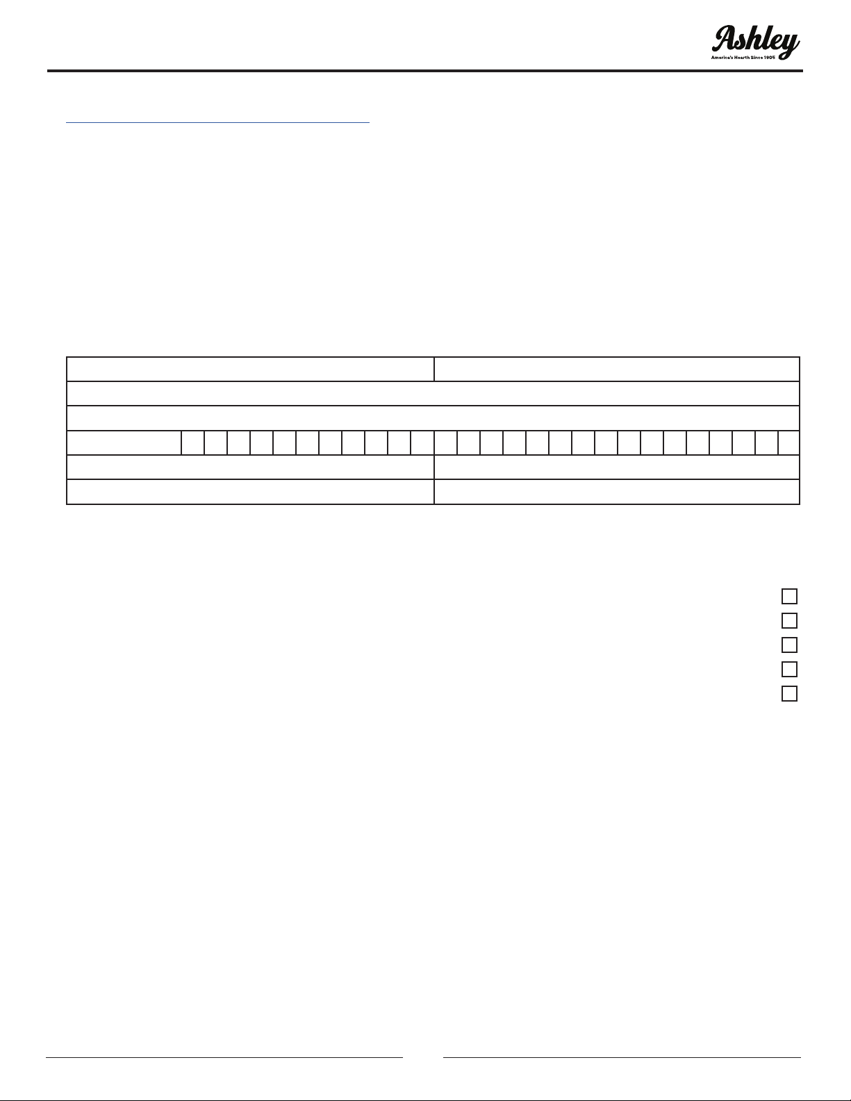
INSTALLATION CHECKLIST
Your Gas Stove should be installed by a qualied installer only. An NFI qualied Installer can be found at
www.ncertied.org/public/nd-an-n-pro/
CUSTOMER SERVICE
1-800-750-2723 ext 5050
Text to 423-301-5624
Email to: Customerservice@usstove.com
COMMISSIONING CHECKLIST
This Checklist is to be completed in full by the qualied person who installs this unit. Keep this page for
future reference.
Failure to install and commission according to the manufacturer’s instructions and complete this checklist
will invalidate the warranty.
Please Print
Customer Name: Telephone Number:
Address:
Model:
Serial Number:
Installation Company Name: Phone Number:
Installation Technician’s Name: License Number:
DESCRIPTION OF WORK
Location of installed appliance: _________________________________________________________________________
COMMISSIONING
Conrm proper placement of internal parts ...........................................................................................................................................
Conrm clearances to combustibles as per installation instructions in this manual .................................................
Conrm the stove starts and operates properly ....................................................................................................................................
Check to ensure a CO alarm is installed as per local building codes and is functional .............................................
Explain the safe operation, proper fuel usage, cleaning, and routine maintenance requirements .................
Declaration of Completion: As the qualied person responsible for the work described above, I conrm that
the appliance as associated work has been installed as per manufacturer’s instructions and following any
applicable building and installation codes.
Signed: ___________________________________Print Name: ______________________________ Date: _____________
Home Owner: RETAIN THIS INFORMATION FOR FUTURE REFERENCE

4
© 2020 United States Stove Company
MASSACHUSETTS RESIDENTS ONLY
REQUIREMENTS FOR THE
COMMONWEALTH OF
MASSACHUSETTS
This product must be installed by a licensed
plumber or gas tter when installed within the
Commonwealth of Massachusetts.
NOTE REGARDING VENTED PRODUCTS
Flex line installation must not exceed 36 inches
and must have a T shutoff valve. Any residence
with a direct vent product must have a CO detector
installed in the residence. Installation of the replace
or vented gas log in the State of Massachusetts
requires the damper to be permanently removed
or welded in the fully open position. In addition,
neither a naturally vented gas log nor a vent-
free product may be installed in a bedroom or
bathroom in the State of Massachusetts. All gas
tting and installation of this heater shall only be
done by a licensed gas tter or licensed plumber.
For all side wall horizontally vented gas fueled
equipment installed in every dwelling, building or
structure used in whole or in part for residential
purposes, including those owned or operated by the
Commonwealth and where the side wall exhaust
vent termination is less than seven (7) feet above
nished grade in the area of the venting, including
but not limited to decks and porches, the following
requirements shall be satised:
INSTALLATION OF CARBON MONOXIDE
DETECTORS
At the time of installation of the side wall horizontal
vented gas fueled equipment, the installing
plumber or gas tter shall observe that a hard wired
carbon monoxide detector with an alarm is installed
on each additional level of the dwelling, building or
structure served by the side wall horizontal vented
gas fueled equipment. It shall be the responsibility
of the property owner to secure the services of
qualied licensed professionals for the installation
of hard wired carbon monoxide detectors. In the
event that the side wall horizontally vented gas
fueled equipment is installed in a crawl space or
an attic, the hard wired carbon monoxide detector
with alarm and battery back-up may be installed on
the next adjacent oor level. In the event that the
requirements of this subdivision can not be met at
the time of completion of installation, the owner
shall have a period of thirty (30) days to comply
with the above requirements; provided, however,
that during said thirty (30) day period, a battery
operated carbon monoxide detector with an alarm
shall be installed.
APPROVED CARBON MONOXIDE
DETECTORS
Each carbon monoxide detector as required in
accordance with the above provisions shall comply
with NFPA 720 and ANSI/UL 2034 listed and IAS
certied.
SIGNAGE
A metal or plastic identication plate shall be
permanently mounted to the exterior of the building
at a minimum height of eight (8) feet above grade
directly in line with the exhaust vent terminal for the
horizontally vented gas fueled heating appliance or
equipment. The sign shall read, in print size no less
than one-half (1/2) inch in size, “GAS VENT DIRECTLY
BELOW, KEEP CLEAR OF ALL OBSTRUCTIONS”.
INSPECTION
The state or local gas inspector of the side wall
horizontally vented gas fueled equipment shall not
approve the installation unless, upon inspection, the
inspector observes carbon monoxide detectors and
signage installed in accordance with the provisions
of 248 CMR 5.08(2)(a)1 through 4.
EXEMPTIONS
The following equipment is exempt from 248 CMR
5.08(2)(a)1 through 4:
• The equipment listed in Chapter 10 entitled
“Equipment Not Required To Be Vented” in the
most current edition of NFPA 54 as adopted by
the Board; and
• Product Approved side wall horizontally vented
gas fueled equipment installed in a room or
structure separate from the dwelling, building or
structure used in whole or in part for residential
purposes.
MANUFACTURER REQUIREMENTS -
GAS EQUIPMENT VENTING SYSTEM
PROVIDED
When the manufacturer of Product Approved side
wall horizontally vented gas equipment provides
a venting system design or venting system
components with the equipment, the instructions
provided by the manufacturer for installation of the
equipment and the venting system shall include:
© 2020 United States Stove Company
5
• Detailed instructions for the installation of the
venting system design or the venting system
components
• A complete parts list for the venting system
design or venting system.
GAS EQUIPMENT VENTING SYSTEM NOT
PROVIDED
When the manufacturer of a Product Approved
side wall horizontally vented gas fueled equipment
does not provide the parts for venting the ue
gases, but identies “special venting systems”, the
following requirements shall be satised by the
manufacturer:
• The referenced “special venting system”
instructions shall be included with the appliance
or equipment installation instructions; and
• The “special venting systems” shall be Product
Approved by the Board, and the instructions for
that system shall include a parts list and detailed
installation instructions.
A copy of all installation instructions for all Product
Approved side wall horizontally vented gas fueled
equipment, all venting instructions, all parts lists
for venting instructions, and/or all venting design
instructions shall remain with the appliance or
equipment at the completion of the installation.
MASSACHUSETTS RESIDENTS ONLY
SAFETY INFORMATION
WARNING:
READ THIS OWNER’S MANUAL CAREFULLY AND
COMPLETELY BEFORE TRYING TO ASSEMBLE,
OPERATE, OR SERVICE. ANY CHANGE TO
THIS APPLIANCE OR ITS CONTROLS CAN BE
DANGEROUS. IMPROPER INSTALLATION OR
USE CAN CAUSE SERIOUS INJURY OR DEATH
FROM FIRE, BURNS, EXPLOSIONS, ELECTRICAL
SHOCK AND CARBON MONOXIDE POISONING.
IMPORTANT:
VENT-FREE HEATERS ADD MOISTURE TO AIR.
ALTHOUGH THIS IS BENEFICIAL, INSTALLING
HEATER IN ROOMS WITHOUT ADEQUATE
VENTILATION MAY CAUSE MILDEW TO FORM
FROM TOO MUCH MOISTURE.
WARNING:
ANY CHANGE TO THIS HEATER OR ITS
CONTROLS CAN BE DANGEROUS.
WARNING:
FAILURE TO KEEP PRIMARY AIR OPENING(S)
OF THE BURNER(S) CLEAN MAY RESULT IN
SOOT AND PROPERTY DAMAGE.
WARNING:
DO NOT ALLOW FANS TO BLOW DIRECTLY
INTO FIREPLACE. AVOID ANY DRAFTS THAT
ALTER BURNER FLAME PATTERNS.
WARNING:
DO NOT USE A BLOWER INSERT, HEAT
EXCHANGER INSERT OR OTHER ACCESSORY
NOT APPROVED FOR USE WITH THIS HEATER.
NOTE: When burning any unit or appliance that
combusts fuel for heat, such as coal, oil, wood
or natural and (L.P.) liquid petroleum gas, we
highly recommend the use of smoke and carbon
monoxide detectors in your home.
CARBON MONOXIDE POISONING
Early signs of carbon monoxide poisoning are
similar to the u with headaches, dizziness, and/
or nausea. If you have these signs, the stove may
not have been installed properly. Get fresh air at
once! Have the stove inspected and serviced by a
qualied service person. Some people are more
affected by carbon monoxide than others. These
include pregnant women, people with heart or
lung disease or anemia, those under the inuence
of alcohol, and those at high altitudes. Propane/
LP gas and natural gas are both odorless. An odor-
making agent is added to each of these gases. The
odor helps you detect a gas leak. However, the odor
added to these gases can fade. Gas may be present
6
© 2020 United States Stove Company
SAFETY INFORMATION
even though no odor exists. Make certain you read
and understand all warnings. Keep this manual for
reference. It is your guide to the safe and proper
operation of this stove.
CAUTION:
STRONG DRAFTS, SUCH AS A CEILING FAN
PLACED DIRECTLY IN FRONT OF THE HEATER
(PULLING FROM EITHER DIRECTION) MAY
CREATE SOOTING. SOOTING WILL DISCOLOR
WALLS.
1. The installation must conform with local codes
or in the absence of local codes, with National
Fuel Gas Code, ANSI Z223.1/NFPA54. NOTE: See
the “Producing Adequate Air For Combustion
And Ventilation” section of this manual. Never
install this heater:
• In a recreational vehicle, bathroom, bedroom
or any other sleeping quarters.
• Where curtains, furniture, clothing or other
ammable objects are less than 24” from the
front of the heater
• In high trafc areas or in windy areas
2. Two models are available. One specic model
for propane (LP) and one for natural gas. Use
the correct type of gas for your home. Do not
convert from one gas type to another.
3. If this heater is used with propane gas, do
not place propane supply tank(s) inside any
structure.
4. What To Do IF You Smell Gas:
• Shut off the gas supply.
• Do not try to light any appliance.
• Do not touch any electrical switch; do not use
any phone in your building.
• Immediately call your gas supplier from a
neighbor’s phone. Follow the gas supplier’s
instructions.
• If you cannot reach your gas supplier, call the
re department.
5. When operated for the rst time, logs may emit
a “paper burning” smell. This smell will gradually
diminish and will be totally eliminated after the
rst few hours of operation. Run gas logs with
ue damper open during this time. Do not use
blower at this time.
6. This heater shall not be installed in unusually
tight construction unless provisions are provided
for adequate combustion and ventilation air
(see “Producing Adequate Air For Combustion
And Ventilation” section of this manual).
7. The surface of gas logs becomes very hot when
operating. Keep children and adults away from
the hot surface. Gas logs will remain hot for
sometime after shutdown. Allow the surface to
cool before touching.
8. Do not place clothing or other ammable
material on or near the appliance.
9. If equipped, fresh air damper must be closed.
10. Keep the appliance area clean and free from
combustible materials, gasoline, and other
ammable vapors and liquids.
11. If burner shuts off, do not relight until you
provide fresh outside air. If the burner continues
to shut off, have the unit serviced.
12. Do not use this heater if any part has been
under water. Immediately call a qualied
service technician to inspect room heater and
to replace any part of the control system and
any gas control which has been under water.
13. Turn off the heater and let cool before servicing.
14. These logs are made of bonded ber. When
removing logs and base, do not damage the
bonded material. If the material is damaged
extensively, loose ber dust could be emitted
into the air.
15. Any safety screen or guard removed for
servicing an appliance must be replaced before
operating heater.
16. This appliance is intended for supplemental
heating.
17. Installation and repairs should be performed by
a qualied service person. The appliance should
be inspected before use and at least annually
by a professional service person. More frequent
cleaning may be required due to excessive
lint from carpeting, bedding material, etc. It
is imperative that the control compartments,
burners and circulating air passageways of the
appliance be kept clean.
18. All heater screens must be kept closed when
operating gas logs.
© 2020 United States Stove Company
7
SAFETY INFORMATION
19. Do not use this heater for burning trash or
cooking. Never place matches, paper, garbage
or any other material on top of logs or into the
ames.
20. Do not install or operate this heater in areas
where impurities in air exist (such as tobacco
smoke or heavy cooking grease). Particles from
impurities may discolor walls.
21. Due to high temperatures, appliance should be
located out of trafc and away from furniture
and draperies.
22. Children and adults should be alerted to hazards
of high surface temperature and should stay
away to avoid burns or clothing ignition.
23. Young children should be carefully supervised
when they are in same room with appliance.
24. An unvented room heater having an input
rating of more than 10,000 Btu per hour shall
not be installed in a bedroom or bathroom.
25. The appliance and its appliance main gas valve
must be disconnected from gas supply piping
system during any pressure testing of that
system at test pressure in excess of 1/2 psi (3.5
kPa).
26. The appliance must be isolated from gas supply
piping system by closing its equipment shutoff
valve during any pressure testing of gas supply
piping system at test pressures equal to or less
than 1/2 psi (3.5 kPa).
27. A replace screen must be in place when
appliance is operating and unless other
provisions for combustion air are provided,
screen shall have an opening(s) for introduction
of combustion air.
The replace needs to be prepared before installing
the heater.
A. Turn off the gas supply to the replace.
WARNING:
BEFORE INSTALLING IN A SOLID-FUEL
BURNING FIREPLACE, CHIMNEY FLUE AND
FIREBOX MUST BE CLEANED OF SOOT,
CREOSOTE, ASHES AND LOOSE PAINT BY A
QUALIFIED CHIMNEY CLEANER.
WARNING:
ANY OUTSIDE AIR DUCTS AND/OR ASH DUMPS
IN FIREPLACE SHALL BE PERMANENTLY
CLOSED AT TIME OF APPLIANCE
INSTALLATION.
B. Read the following sections before installing
your unit; Installation In A Solid-Fuel Burning
Fireplace, and Producing Adequate Air For
Combustion And Ventilation.
WARNING:
CUTTING ANY SHEET-METAL PARTS OF
SOLID FUEL BURNING FIREPLACE OR LISTED
VENTLESS FIREBOX ENCLOSURE IN WHICH
UNVENTED FIREPLACE INSERT IS TO BE
INSTALLED IS PROHIBITED.
NOTE: IF FACTORY BUILT FIREPLACE HAS NO GAS
ACCESS HOLE(S) PROVIDED, AN ACCESS HOLE
OF 1.5 inch (37.5mm) DIAMETER OR LESS MAY BE
DRILLED THROUGH LOWER SIDES OR BOTTOM OF
FIREBOX IN A PROPER WORKMANLIKE MANNER.
THIS ACCESS HOLE MUST BE PLUGGED WITH
NON-COMBUSTIBLE INSULATION AFTER GAS
SUPPLY LINE HAS BEEN INSTALLED. REFRACTORY,
GLASS DOORS, SCREEN RAILS, SCREEN MESH,
AND SOLID-FUEL LOG GRATES (IF APPLICABLE)
CAN BE REMOVED FROM FIREPLACE BEFORE
INSTALLING UNVENTED FIREPLACE INSERT.
This is an unvented gas-red heater. It uses
air (oxygen) from room in which it is installed.
Provisions for adequate combustion and
ventilation air must be provided. Refer to the
section,” Producing Adequate Air For Combustion
And Ventilation" in this manual. This appliance
may be installed in an aftermarket, permanently
located, manufactured (mobile) home, where
not prohibited by local codes. This appliance is
only for use with type of gas indicated on rating
plate. This appliance is not convertible for use
with other gases.
8
© 2020 United States Stove Company
INSTALLATION INFORMATION
CLEARANCES
www.ncertied.org
We recommend that our gas
hearth products be installed
and serviced by profes-
sionals who are certied in
the U.S. by the National
Fireplace Institute® (NFI) as
NFI Gas Specialists.
US Stove highly recommends your stove be
installed by a qualied NFI technician. To nd
the nearest qualied installer, go to:
https://ncertied.org,
To ensure a safe installation into the masonry or
factory-built replace, the following instructions
must be carefully followed:
1. Sidewall Clearances - Clearance from the
side of the replace opening to any adjacent
combustible wall should not be less than 7” on
the right and left side.
2. Ceiling Clearances - The ceiling height should
not be less than 24” from the top of the replace
opening.
3. Mantel Clearances - Clearances from top of the
heater to mantel or mantel supports should not
be less than 20”.
NOTE: See the following sections for installation
options: Installation In A Solid-Fuel Burning
Fireplace and Installation With Optional Wooden
Mantel and Zero Clearance Installation.
WARNING:
ANY CHANGE TO THIS HEATER OR ITS
CONTROLS CAN BE DANGEROUS.
GAS CONNECTION
Check gas type. Use only the type of gas indicated
on the valve rating plate. If the type of gas listed on
the plate is not your type of gas supply, DO NOT
INSTALL. Contact your dealer for the proper model.
Always use an external regulator for all LP heaters
to reduce supply tank pressure to a maximum of 13”
W.C. This is in addition to regulator furnished with
heater.
WARNING:
CONNECTION DIRECTLY TO AN UNREGULATED
LP TANK CAN CAUSE AN EXPLOSION.
Normal gas connection is 3/8” N.P.T. made at the
left rear side of the appliance (facing front of the
appliance). NOTE: The connecting pipe must be
internally tinned copper tubing for use with natural
gas. Test for leaks using a solution of soap and
water after completing the connection. DO NOT
USE OPEN FLAME.
WARNING:
INSTALLATION AND REPAIRS SHOULD BE
PERFORMED BY A QUALIFIED SERVICE PERSON.
THE APPLIANCE SHOULD BE INSPECTED
BEFORE USE AND AT LEAST ANNUALLY BY
A PROFESSIONAL SERVICE PERSON. MORE
FREQUENT CLEANING MAY BE REQUIRED
DUE TO EXCESSIVE LINT FROM CARPETING,
BEDDING. MATERIAL, ETC. IT IS IMPERATIVE
THAT CONTROL COMPARTMENTS, BURNERS
AND CIRCULATING AIR PASSAGEWAYS OF
APPLIANCE BE KEPT CLEAN.
AFTER MARKET MOBILE HOME
INSTALLATION
NOTE: See “Producing Adequate Air For Combustion
And Ventilation” section of this manual.
THIS APPLIANCE MAY BE INSTALLED IN AN
AFTERMARKET*, PERMANENTLY LOCATED,
MANUFACTURED (MOBILE) HOME, WHERE NOT
PROHIBITED BY LOCAL CODES.
*After Market: Completion of sale, not for purpose of
resale from the manufacturer.
THIS APPLIANCE IS ONLY FOR USE WITH TYPE
OF GAS INDICATED ON RATING PLATE. THIS
APPLIANCE IS NOT CONVERTIBLE FOR USE WITH
OTHER GASES.
NOTE: For a mobile home installation follow the
“Installation” sections in this manual.
NOTE: See “Producing Adequate Air for Combustion
And Ventilation” section of this manual.
LOG SET PLACEMENT
Although your gas logs are very realistic in
appearance, it is not a real burning replace and
must not be used for burning rejected material.
© 2020 United States Stove Company
9
INSTALLATION INFORMATION
• To avoid irreparable damage to the heater or
personal injury, matches, paper, garbage or any
other material must not be placed or thrown on
top of logs or into ames.
• To avoid personal injury, do not touch hot surfaces
when the heater is operating.
• Close supervision is necessary when the heater is
being operated near children.
WARNING:
• THE LOGS ARE MANUFACTURED FROM
BONDED CERAMIC FIBER. THIS IS A
COMMONLY USED MATERIAL IN INDUSTRY
WORLDWIDE. IN EVENT THAT A LOG
SHOULD BE REMOVED, CARE SHOULD
BE TAKEN NOT TO DAMAGE BONDED
MATERIAL. INTENTIONAL MISUSE OR
DELIBERATELY FRAGMENTING MATERIAL
COULD LEAD TO INHALING FIBERS AND BE
HAZARDOUS TO YOUR HEALTH.
• THIS HEATER IS INTENDED FOR USE AS A
GAS HEATER FIREPLACE AS DESCRIBED
IN THESE INSTRUCTIONS. IT SHOULD IT
SHOULD NOT BE USED FOR ANY OTHER
PURPOSE.
• FAILURE TO POSITION PARTS IN
ACCORDANCE WITH THESE DIAGRAMS OR
FAILURE TO USE ONLY PARTS SPECIFICALLY
APPROVED WITH THIS HEATER MAY RESULT
IN PROPERTY DAMAGE OR PERSONAL
INJURY.
WARNING:
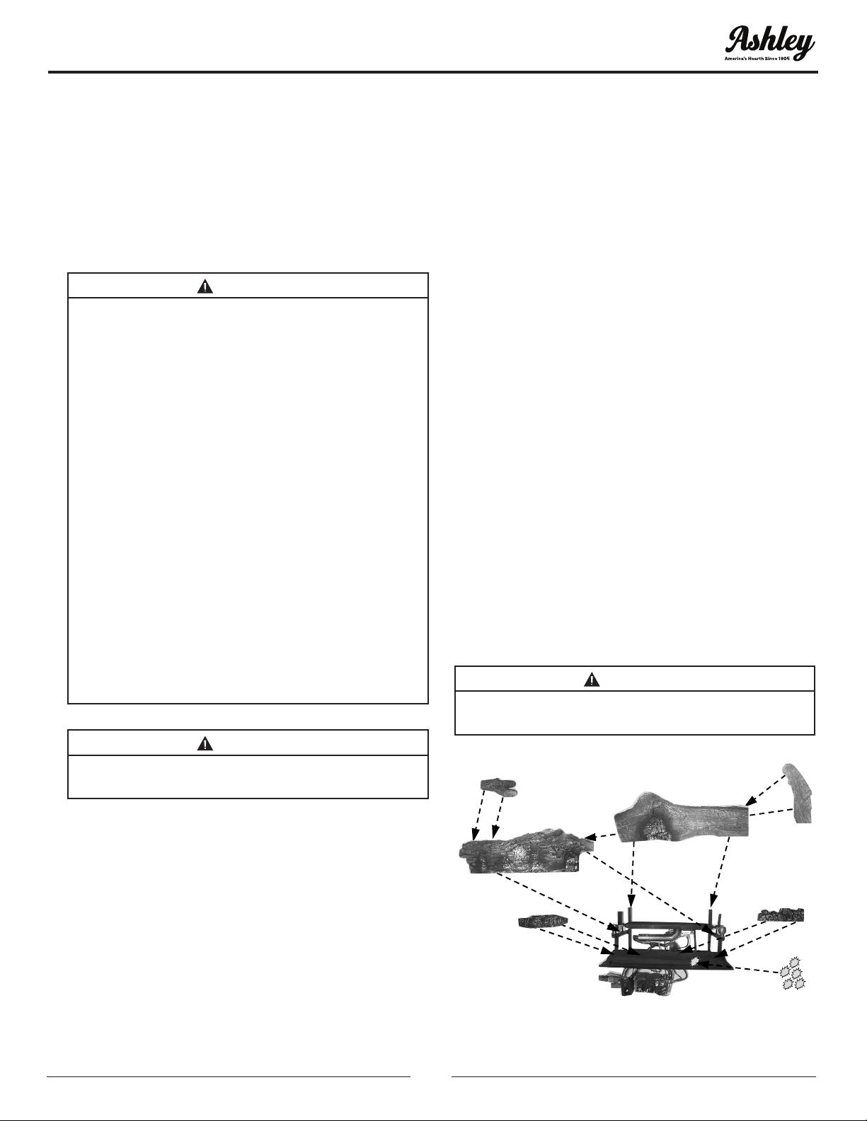
POSITIONING OF LOGS IS VERY CRITICAL SEE
LOG DIAGRAM
(#1) Rear Log, (#2) Middle Log, (#3) Left Front Log,
(#4) Right Front Log, (#5) Left Top Middle Log, (#6)
Right Top Middle Log, (#7) Glowing Embers in front
of #3 & #4 logs.
IMPORTANT: Place log ve on the left and log six on
the right. If they are not properly installed they will
be loose and may cause damage to the appliance.
1. Place rear log #1 on rear log supports. The log
has alignment notches on each rear corner.
2. Place Middle log #2 in front of rear burner tube
and then move log forward. The log should seat
just behind brass knob(s), located in the middle
section of the base between rear burner tube
and front burner pan.
3. Place Left Top Middle log #5 on pins located on
the left top section of Middle log #2.
4. Place Right Top Middle log #6 on pin located on
the right top section of Middle log #2 and align
the notch on right side #6 with side shield on
right.
5. Place Left Front log #3 on locator pins located
on the left middle section of the front burner
pan.
6. Place Right Front log #4 on locator pins located
on the right middle section of the front burner
pan.
7. Provided with your log set is a package of
Glowing Embers (rock wool). Open the package
and tear off small pieces of wool material and
place it over small holes (ports) located on the
front burner pan in front of logs #3 and #4. Cover
the entire section of holes (ports).*Replacement
of loose (Glowing Wool) must be purchased
from the original manufacturer and application
of excess loose material may adversely affect
the performance of the heater.
NOTE: Wash your hands immediately after coming
in contact with wool material. The wool can cause
slight itching or burning in some cases, avoid any
contact with eyes.
WARNING:
ALL PREVIOUSLY APPLIED LOOSE MATERIAL
MUST BE REMOVED PRIOR TO REPLACEMENT.
1
2
5
3
4
6
7
10
© 2020 United States Stove Company
INSTALLATION INFORMATION
1
2
5
3
4
6
7
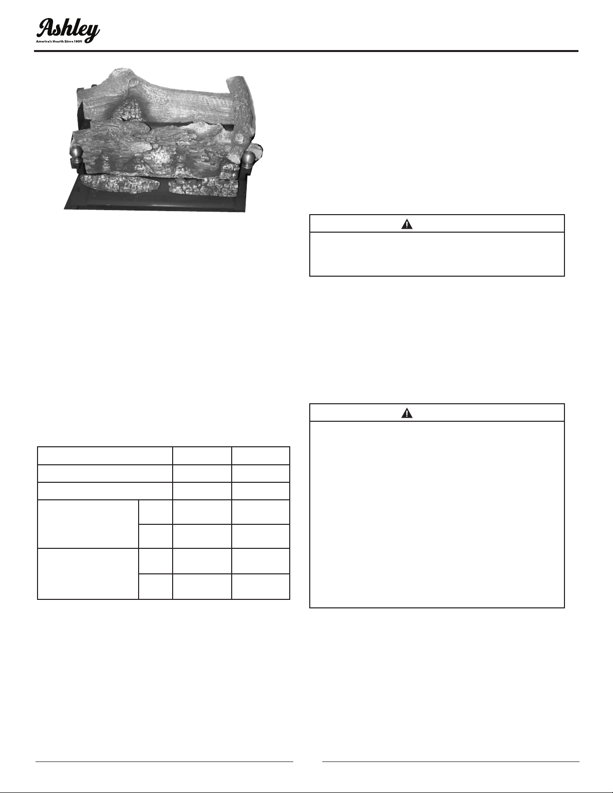
* LOG SET PART NUMBER 892464
GAS PRESSURE CHECK
Check inlet pressure to the burner to ensure that it
is as shown in the table below.
NOTE: The pressure checkpoint is located on the
right side of the valve facing burner, for SIT Millivolt.
The appliance and its main gas valve must be
disconnected from the gas supply piping system
during any pressure testing of that system at test
pressures in excess of 1/2 psi (3.5kPa). The appliance
must be isolated from the gas supply piping system
by closing its equipment shut-off valve during any
pressure testing of gas supply piping system at test
pressures equal to or less than 1/2 psi (3.5 kPa).
Gas Type Natural LP
Maximum Heat Input 33,000 33,000
Minimum Heat Input 23,000 23,000
Gas Inlet Pressure
Max 10.5” W.C. 13” W.C.
Min 5.0” W.C. 11” W.C.
Manifold Pressure
Max 3.5” W.C. 10.0” W.C.
Min 3.0” W.C. 8.2” W.C.
NOTE: On initial installation, it may be necessary to
bleed out the air in the gas lines. Do this by holding
the control knob and turning the knob to the “Pilot”
position for about 30 seconds. To check the regulator
pressure, remove the pressure tag plug at the left
side of the regulator facing the heater. The pressure
should be checked with the heater burning and the
control set on high. After measuring the pressure,
replace the pressure tap plug, ensuring that there
are no leaks.
• For the purpose of minimum input adjustment.
WARNING:
THIS APPLIANCE IS EQUIPPED FOR (NATURAL
OR PROPANE) GAS. FIELD CONVERSION IS
NOT PERMITTED.
Solid fuels shall not be burned in the same replace
where an unvented room heater has been installed.
NOTE: The following label has been provided with
this appliance and must be read and then attached
to the oor of the replace or rebox area beneath
the appliance. Peel and stick the label. Make sure
the area is cleaned before attaching the label to it.
WARNING:
THIS SOLID-FUEL BURNING FIREPLACE OR
LISTED VENTLESS ENCLOSURE HAS BEEN
CONVERTED FOR USE WITH AN UNVENTED
FIREPLACE INSERT ONLY. A SOLID-FUEL
BURNING FIREPLACE CANNOT BE USED FOR
BURNING WOOD OR SOLID FUELS UNLESS ALL
ORIGINAL PARTS HAVE BEEN REPLACED AND
FIREPLACE RE-APPROVED BY THE AUTHORITY
HAVING JURISDICTION. A VENTLESS FIREBOX
ENCLOSURE CANNOT BE USED WITH AN
UNVENTED GAS LOG UNLESS ALL ORIGINAL
PARTS HAVE BEEN REPLACED AND VENTLESS
FIREBOX ENCLOSURE REAPPROVED BY
AUTHORITY HAVING JURISDICTION.
© 2020 United States Stove Company
11
Before operating this appliance, proceed through
the following checklist.
1. Read and understand these instructions before
operating this appliance.
2. Check that there are no gas leaks. If you smell
gas do not attempt to light this appliance.
3. Verify that log placement is correct.
WARNING:
ANY CHANGE TO THIS HEATER OR ITS
CONTROLS CAN BE DANGEROUS.
WARNING:
IF YOU DO NOT FOLLOW THESE INSTRUCTIONS
EXACTLY, A FIRE OR EXPLOSION MAY RESULT
CAUSING PROPERTY DAMAGE, PERSONAL
INJURY OR LOSS OF LIFE.
LIGHTING INSTRUCTIONS SIT-
MILLIVOLT VALVE FOR YOUR SAFETY
READ BEFORE LIGHTING
A. When lighting the pilot follow these instructions
exactly. If piezo fails, then light pilot using
matches. Refer to Manual Lighting Instructions.
B. BEFORE LIGHTING smell all around the
appliance area for gas. Be sure to smell next to
the oor because some gas is heavier than air
and will settle to the oor.
WHAT TO DO IF YOU SMELL GAS
• Do not try to light any appliance.
• Do not touch any electric switch; do not use any
phone in your building.
• Immediately call your gas supplier from a
neighbor’s phone. Follow the gas supplier’s
instructions.
• If you cannot reach your gas supplier, call the re
department.
C. Use only your hand to push in or turn the gas
knob. Never use tools. If the knob will not push
in or turn by hand, don’t try to repair it. Call a
qualied service technician. Force or attempted
repair may result in a re or explosion.
D. Do not use this appliance if any or part of it has
been under water. Immediately call a qualied
service technician to inspect the appliance and
to replace any part of the control system and
any gas control which has been under water.
WARNING:
FIREPLACE SCREENS MUST BE CLOSED WHILE
THE APPLIANCE IS IN OPERATION.
LIGHTING INSTRUCTIONS
1. STOP! Read all safety information.
2. Make sure the manual shutoff valve is fully
closed. If equipped with a thermostat, set it to
the lowest setting.
3. Turn off all electrical power to the appliance.
4. Open access door located at the bottom front
of the appliance.
5. Push in gas control knob slightly and turn
clockwise to the “Off” position.
NOTE: Knob cannot be turned from “Pilot” to “Off”
unless knob is pushed in slightly. Do not force.
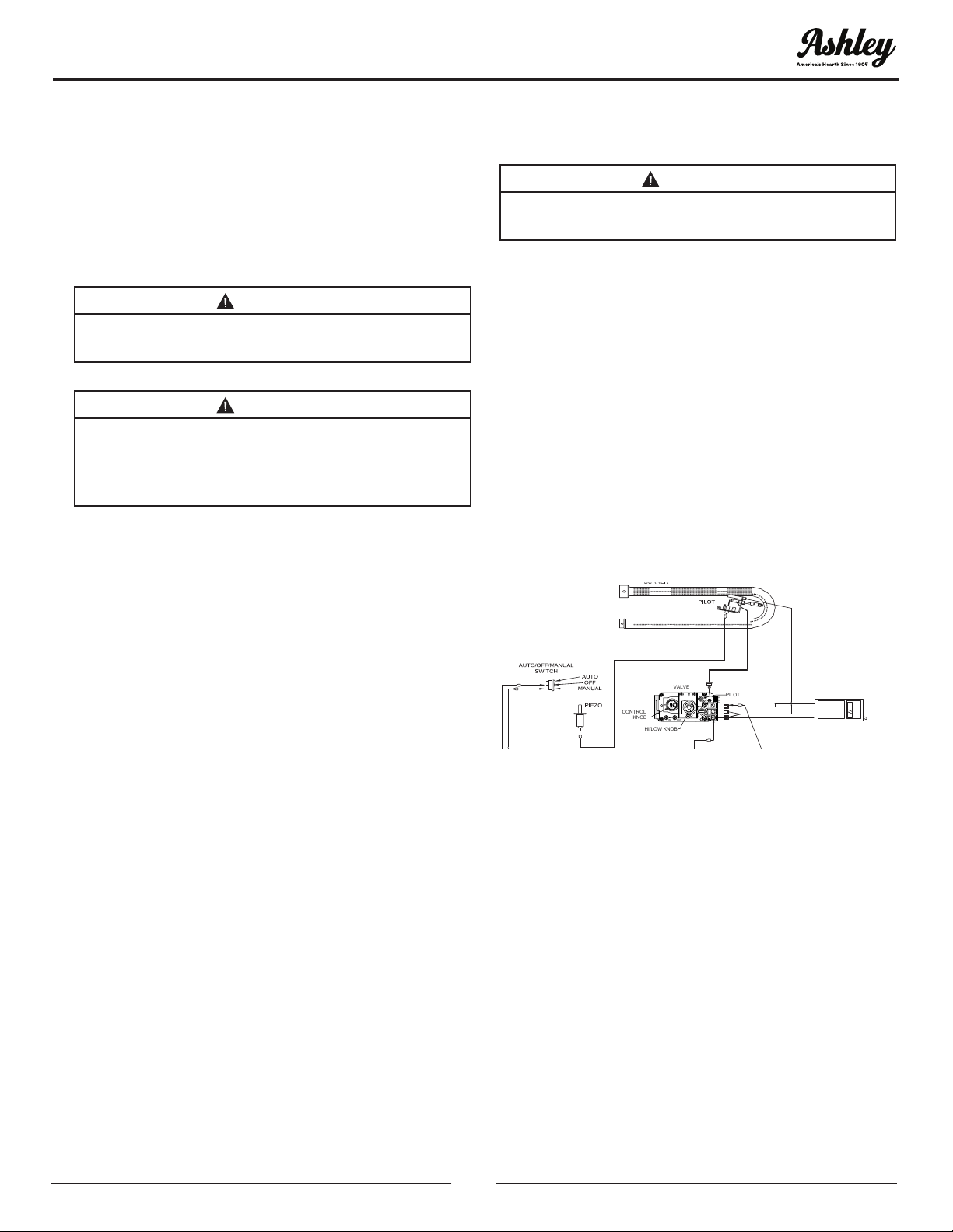
REMOTE CONTROL O
R
WALL THERMOSTAT
IN
L
O
H
OUT
O
P
I
L
T
I
O
F
F
O
N
CONTROL
KNOB
HI/LOW KNOB
PILOT
VALVE
6. Wait (5) ve minutes to clear out any gas.
Then smell for gas, including near the oor. If
you smell gas, STOP! Follow “B” in the safety
information section of this manual. If you don’t
smell gas, go to the next step.
7. The pilot is located in front of the rear log and
burner on the right-hand side of the appliance.
Fully open the manual shutoff valve.
8. Press in and turn the knob on gas control
counterclockwise to “PILOT” and continue
pressing in knob for (15) fteen seconds.
9. With the control knob pressed in, push down
(in) and release the ignitor button (ignitor
button is located on the front left-hand side of
the appliance). This will light the pilot. If needed,
keep repeating this step until pilot lights.
10. Keep the control knob pressed in for (1) one
minute after lighting pilot. After (1) minute,
OPERATING INSTRUCTIONS
12
© 2020 United States Stove Company
OPERATING INSTRUCTIONS
release the control knob and it will pop back up.
The pilot should remain lit. If the pilot goes out,
repeat steps 1 through 9.
• If knob does not pop up when released, stop and
immediately call your service technician or gas
supplier.
• If the pilot will not stay lit after several tries, turn
the gas control knob to the “Off” position and call
your services technician or gas supplier.
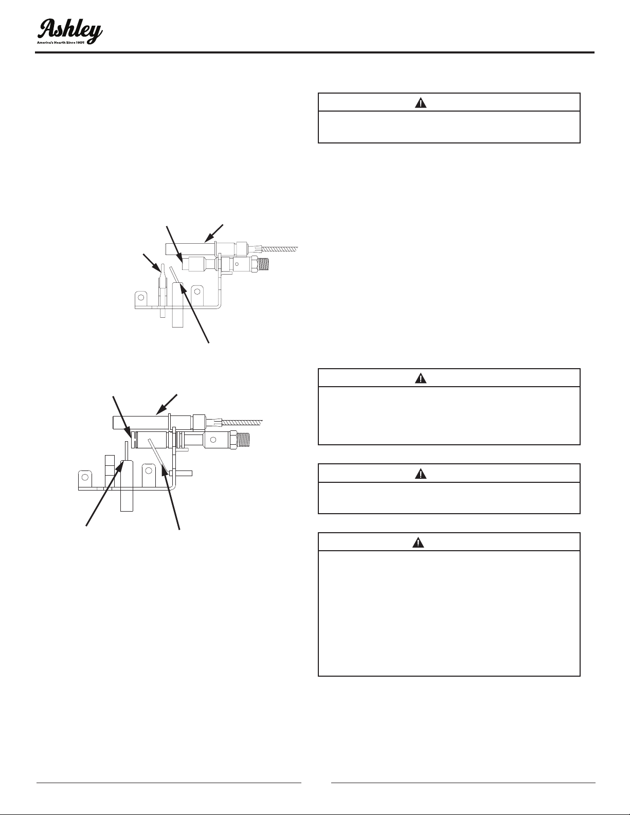
IGNITOR ELECTP
THERMO-COUPLE
GENERATORPILOT
NAT
IGNITOR ELECTP
GENERATORPILOT
THERMO-COUPLE
LP
11. Turn the control knob counterclockwise to “On”.
12. If using the unit without a wall thermostat
place the Off/Manual (Off/Man) switch into the
manual position. If using a wall thermostat place
Auto/Off /Manual (Man) switch to the “Auto” or
“Off” position and place thermostat to a setting
higher than the room’s temperature.
13. Close access cover door.
14. Turn on all electrical power to the appliance.
15. Your heater is equipped with a Hi & Lo control.
Turn clockwise for Low and counterclockwise
for High.
16. Close the access cover door.
TO TURN OFF GAS TO APPLIANCE
CAUTION:
DO NOT TRY TO ADJUST HEATING LEVELS BY
USING MANUAL SHUTOFF VALVE.
SHUTTING OFF UNIT
1. Open access cover door.
2. If equipped with a thermostat set to the lowest
setting.
3. Turn the control knob fully clockwise to the
“Off” position.
4. Turn off all electric power to the appliance if
service is to be performed.
5. Close access cover door
SHUTTING OFF BURNER ONLY (Pilot stays lit.)
1. Turn control knob clockwise to the “Pilot”
position.
CAUTION:
HOT WHILE IN OPERATION. DO NOT TOUCH.
KEEP CHILDREN, CLOTHING, FURNITURE,
GASOLINE AND OTHER LIQUIDS HAVING
FLAMMABLE VAPORS AWAY.
CAUTION:
DO NOT TRY TO ADJUST HEATING LEVELS BY
USING MANUAL SHUTOFF VALVE.
WARNING:
IMPROPER INSTALLATION, ADJUSTMENT,
ALTERATION, SERVICE OR MAINTENANCE
CAN CAUSE PROPERTY DAMAGE, PERSONAL
INJURY OR LOSS OF LIFE. REFER TO THE
OWNER’S INFORMATION MANUAL PROVIDED
WITH THIS APPLIANCE. INSTALLATION
AND SERVICE MUST BE PERFORMED BY A
QUALIFIED INSTALLER, SERVICE AGENCY OR
GAS SUPPLIER.
© 2020 United States Stove Company
13
IMPORTANT:
ALWAYS OPERATE THE APPLIANCE AT
COMPLETELY “ON” OR COMPLETELY “OFF”
POSITIONS. NEVER USE THE HEATER AT A
SETTING BETWEEN THESE POSITIONS AS THIS
CAN RESULT IN IMPROPER COMBUSTION AND
EXCESSIVE CARBON MONOXIDE EMISSIONS.
MANUAL LIGHTING PROCEDURE
If the pilot will not light using the piezo ignitor, you
can light the pilot with a long neck lighter.
1. Locate The Pilot: follow the metal tube from the
gas control. The pilot is located behind the rear
burner tube and in front of the rear log.
2. Press in and turn the gas control knob
counterclockwise to the “PILOT” position.
3. Light the lighter and place it near the pilot.
4. Once the pilot is lit, continue to hold the knob
for (15) fteen seconds.
5. Follow steps 8 through 10 of the “Lighting
instructions”.
NOTE: This unit may be used with an optional
wall thermostat. If so, the wall thermostat needs
to be set at a higher temperature than the room
temperature.
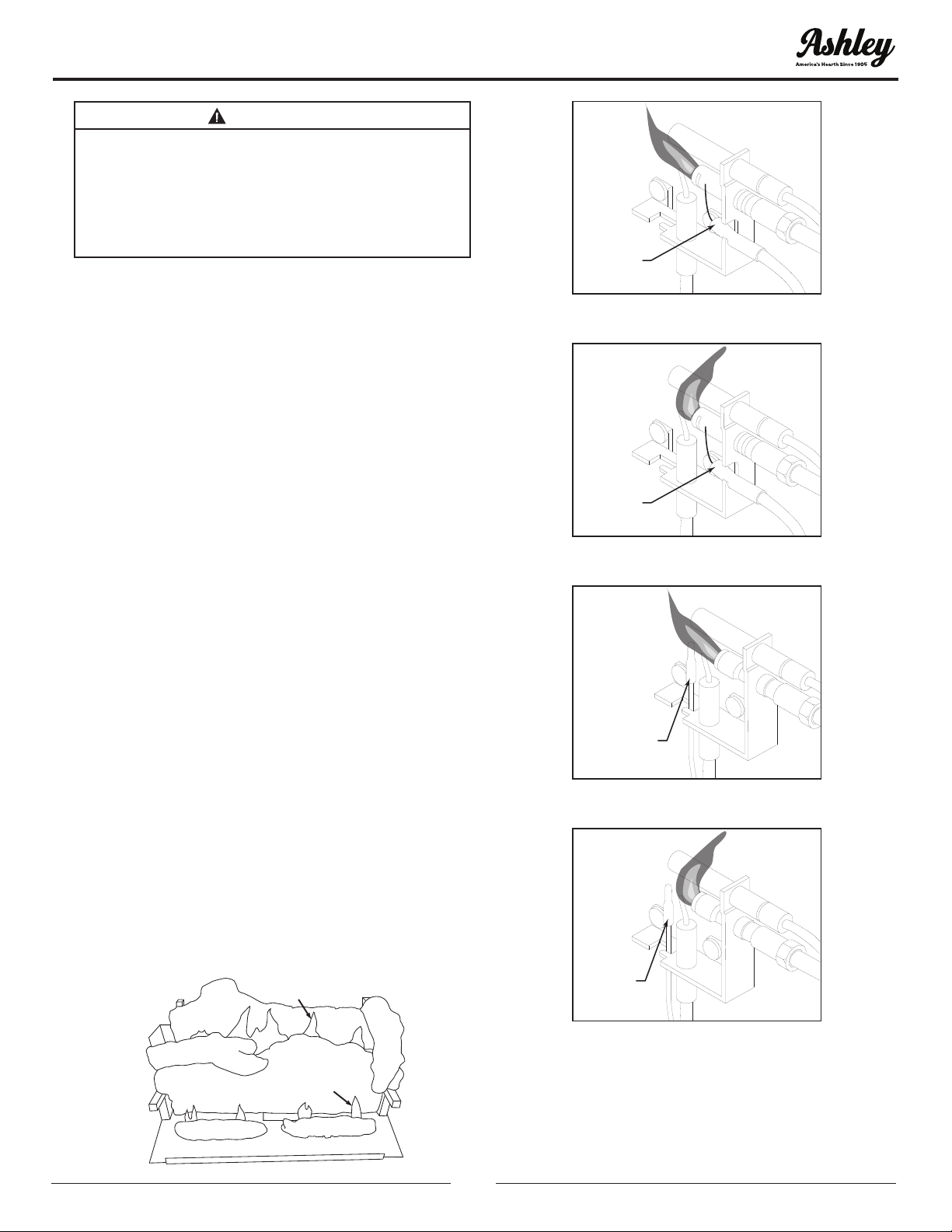
FLAME CHECK
A periodic check of the ames should be made. The
pilot ame should always be present when gas logs
are in operation.
Rear Flames: The ames at the rear or at either
side of the top log should be a very similar yellow
color, and should be about 3” to 4” above large rear
log for natural gas logs and about 6” for propane
(LP) gas log sets.
Front Flame: The ame should be 1-1/2” to 2”
high and touch the back of the front log. This will
produce a red glow on this log.
3” to 4” above large rear log for
natural gas logs and about 6” for
propane (LP) gas log sets
1-1/2” to 2” high and touch the
back of front log
Correct Pilot Flame Appearance
Thermocouple
for LP
LP
Incorrect Pilot Flame Appearance
Thermocouple
for LP
LP
Correct Pilot Flame Appearance
Thermocouple
for Natural
NAT
Incorrect Pilot Flame Appearance
Thermocouple
for Natural
NAT
OPERATING INSTRUCTIONS
14
© 2020 United States Stove Company
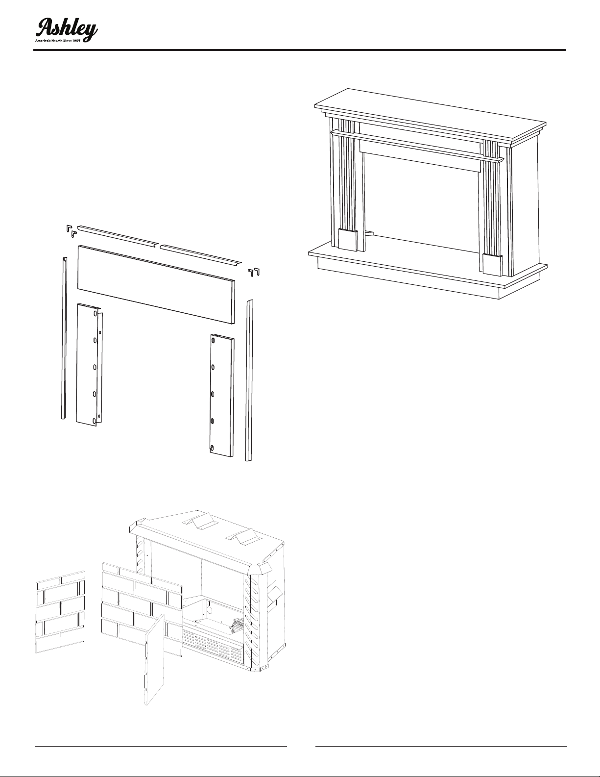
OPTIONAL KITS
There are optional kits available for your stove.
These are listed below:
• Insert Fireplace Facade
• Wooden Surround
• Brick Panel Kit
• Stainless Steel Kit
For more information on these kits contact your
local representative or appliance manufacture.
AG34IK INSERT KIT
AG34BK BRICK INSERT KIT
AG34MK MANTEL KIT
© 2020 United States Stove Company
15
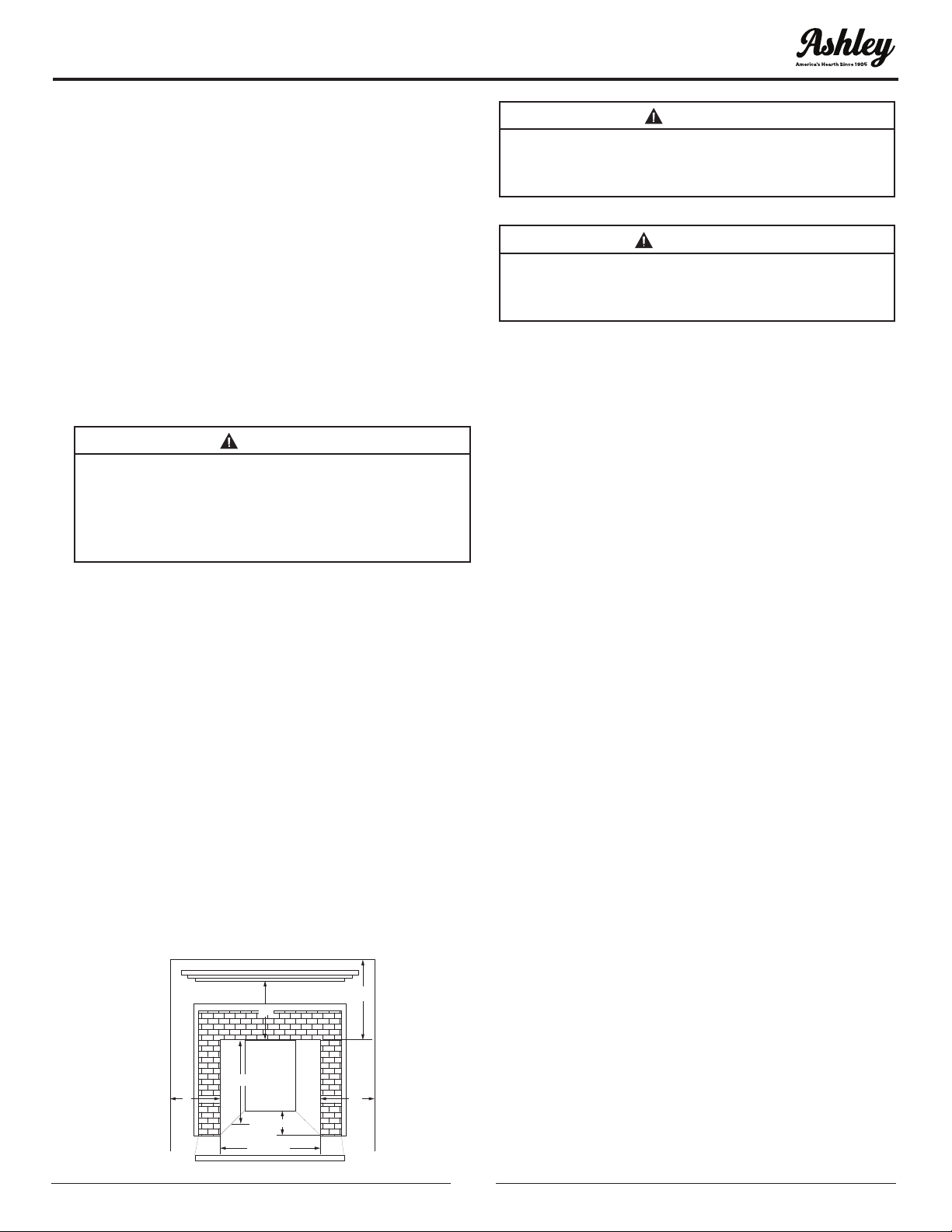
INSTALLATION
SOLID FUEL BURNING FIREPLACES
INSTALLATION
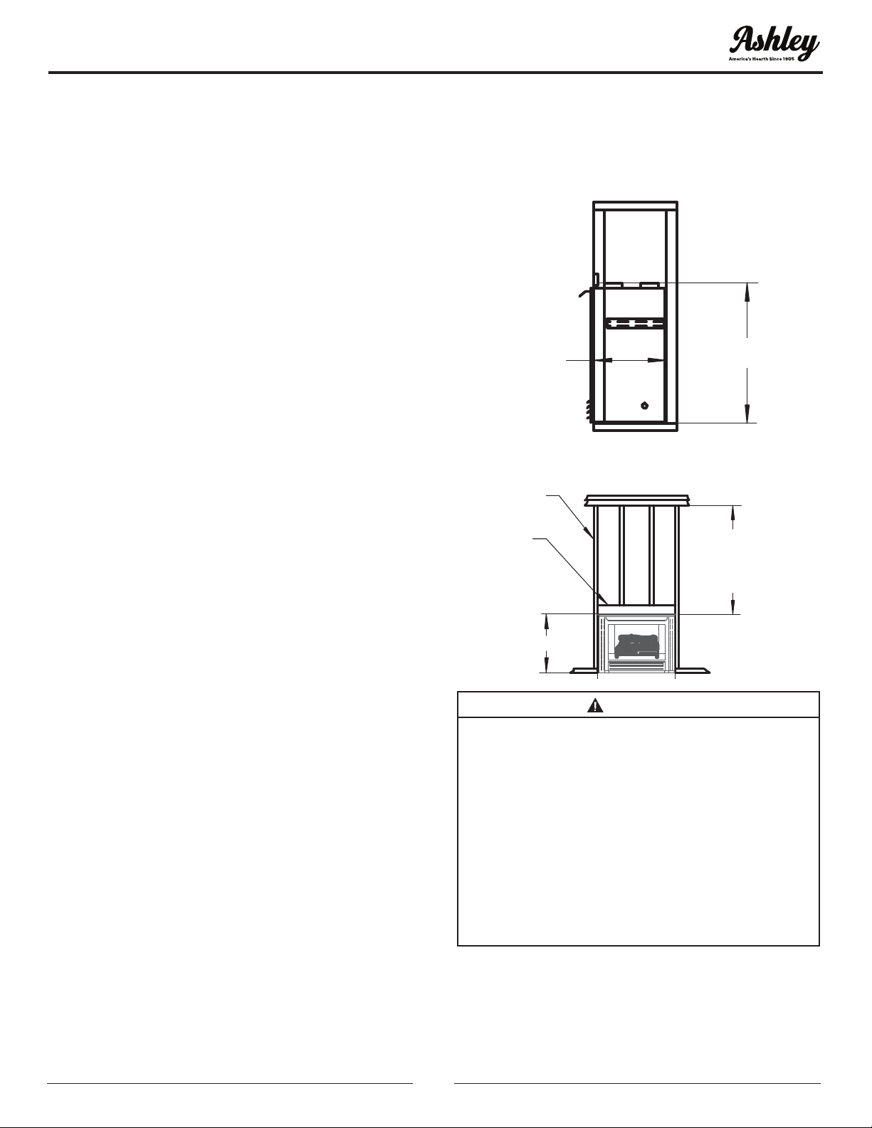
This model may be installed in a masonry replace.
The gure below demonstrates the required
dimensions.
NOTE: See “Producing Adequate Air for Combustion
And Ventilation” section of this manual.
NOTE: Installer of this appliance must mechanically
(peel and stick) attach marking supplied with this
unvented appliance before installing to inside
of rebox of solid-fuel burning replace or listed
ventless rebox enclosure into which unvented
replace insert is installed (see the “Gas Pressure
Check” section of this manual).
CAUTION:
CUTTING ANY SHEET-METAL PARTS OF
A SOLID-FUEL BURNING FIREPLACE OR
LISTED VENTLESS ENCLOSURE IN WHICH AN
UNVENTED FIREPLACE IS TO BE INSTALLED IS
PROHIBITED.
NOTE: If the factory-built replace has no gas
access hole(s) provided, an access hole of 1.5” (37.5)
diameter or less may be drilled through lower
sides or bottom of rebox in a proper workmanlike
manner. This access hole must be plugged with
non-combustible insulation after the gas supply
line has been installed.
Refractory, glass doors, screen rails, screen mesh,
and solid-fuel log grates (if applicable) can be
removed from the replace before installing an
unvented replace insert.
NOTE: After the unit is positioned in the replace,
mark the trim panels as follows:
A. Set the side panels in place, at against the
replace. Mark a line down the inside edge of
the trim panel to make a vertical reference line.
24"
7"
25 - 1/8”
35 - 9/16”
13 - 3/4”
7"
20"
CAUTION:
TRIM PANELS OR SURROUNDS SHALL NOT
SEAL VENTILATION OPENINGS IN THE
FIREPLACE.
ATTENTION:
SMOKE SHELVES, SHIELDS, AND BAFFLES MAY
BE REMOVED IF ATTACHED BY MECHANICAL
FASTENERS.
ZERO CLEARANCE INSTALLATION
The installation must conform with local codes or in
the absence of local codes, with National Fuel Gas
Code, ANSI Z223.1/NFPA54.
This appliance may be installed in an After-Market*
Manufactured (Mobile) Home, where not prohibited
by state or local codes.
* (After Market: Completion of sale, not for
purpose of resale from manufacturer).
This appliance is only for use with the type of gas
indicated on the certication plate. This appliance
is not convertible for use with other gases.
NOTE: See “Producing Adequate Air For Combustion
And Ventilation”
CHOOSING THE LOCATION FOR YOUR
FIREPLACE
The provided gures show some of the many ways
your replace may be installed. Consider trafc
patterns in your room and location of doors and
windows. Moving air from ceiling fans, open doors,
and hot air grills may cause ames to soot. If a
disturbance is found that affects ames, it must be
eliminated by turning off the ceiling fan, closing
door or closing or moving hot air register. A corner
location may be best where space is limited.
Your replace weighs no more than some of your
ne furniture. If the replace is located near a load-
bearing wall, additional supports to the foundation
will not be necessary. HEAVY FACINGS, SUCH AS
BRICK, STONE, ETC., MAY REQUIRE ADDITIONAL
FOUNDATION SUPPORT.
NOTE: If this appliance is installed directly on
carpeting, tile or other combustible material, other
than wood ooring, the appliance shall be installed
on a metal or wood panel extending full width and
depth of the appliance.
16
© 2020 United States Stove Company
INSTALLATION
The Manufacturers Trim Kit must be used for Zero
Clearance Installation. See the “Insert Fireplace
Facade Installation” section of this manual for
replace installations.
GAS LINE
The gas supply line and electrical supply must
be installed before framing in the replace by a
licensed installer.
DRAFTS
Do not locate the replace in high trafc areas or
areas exposed to high drafts and winds. Locate the
replace away from furniture and draperies.
ROOM
DIVIDER
PARTIAL ROOM
PROJECTION
FULL ROOM PROJECTI ON
FLUSH
C
ORNER
WARNING:
SOLID-FUELS SHALL NOT BE BURNED IN A
FIREPLACE IN WHICH AN UNVENTED ROOM
HEATER IS INSTALLED.
CAUTION:
ANY OUTSIDE AIR DUCTS AND/OR ASH DUMPS
IN THE FIREPLACE SHALL BE PERMANENTLY
CLOSED AT TIME OF APPLIANCE
INSTALLATION.
WARNING:
BEFORE INSTALLING IN A SOLID-FUEL
BURNING FIREPLACE, THE CHIMNEY FLUE
AND FIREBOX MUST BE CLEANED OF SOOT,
CREOSOTE, ASHES AND LOOSE PAINT BY A
QUALIFIED CHIMNEY CLEANER.
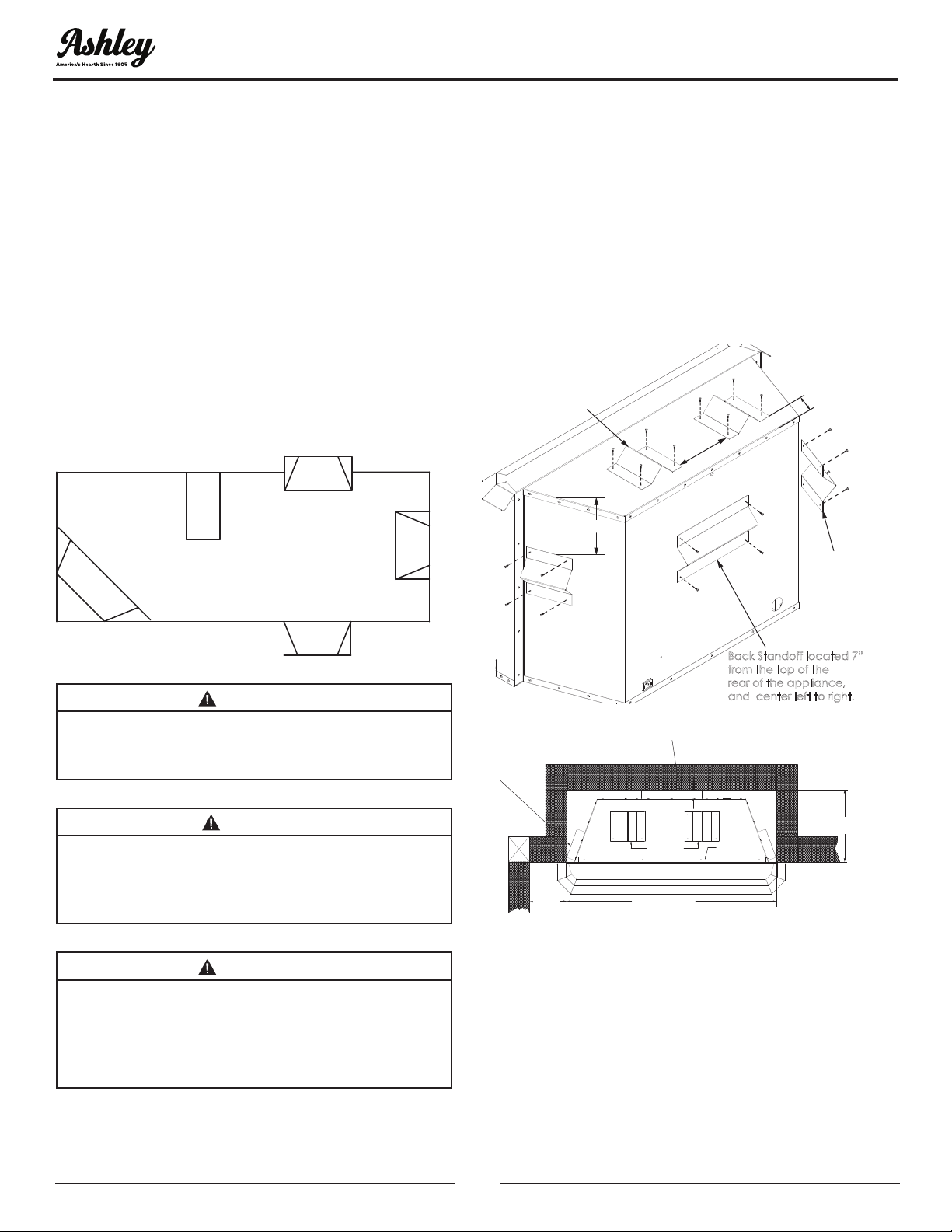
ZERO CLEARANCE STANDOFF(S)
ASSEMBLY
NOTE: All Standoff must be attached to the
appliance before installing as a Zero Clearance
appliance.
Follow the instructions given in the diagrams below
exactly.
NOTE: If installing with the mantel kit refer to the
instructions included with the mantel kit for correct
installation.
Back Standoff located 7”
from the top of the
rear of the appliance,
and center left to right.
Top Standoff
(2 per unit)
Side Standof
f
(2 per unit)
6-5/8”
2”
7”
Side Standoff
35-/9/16” OPENING FOR
UNIT
13-3/4” MIN.
1.5”
7” FROM
OPENING
TO WALL.
Rear-Standoff
Top Trim PanelTop-Standoffs
FIREPLACE CLEARANCES (ZC)
The stove may be placed directly on a combustible
oor, against a combustible wall at marked
clearances or on a raised wooden platform. If
the stove is to be installed on a raised wooden
platform, the platform must be a continuous level
surface. The replace must be secured in place so
it cannot shift positions. Only header (see below)
© 2020 United States Stove Company
17
may rest on standoffs on top of the rebox. When
the rebox is installed over carpeting, vinyl tile, or
any combustible material other than wood ooring,
it must be installed on a metal or wood panel
extending its full width and depth. Alternatively,
carpeting, vinyl tile, etc. may be removed beneath
the unit before installing.
INSTALLING FIREBOX (ZC)
This list of specic instructions will help you
make certain that every installation operation is
performed correctly. Complete installation steps in
the sequence shown.
LOCAL BUILDING CODES SHOULD BE CONSULTED
IN ALL CASES AS TO PARTICULAR REQUIREMENTS
CONCERNING INSTALLATION OF FACTORY BUILT
FIREPLACES. Select location for replace by taking
into consideration factors previously outlined in
“Choosing the Location.”
FRAMING FIREBOX
Width of the framed opening must be as shown
in the adjacent gures. The entire replace can be
elevated above the oor to achieve a raised hearth
effect. This can be done by adding a small platform
to achieve the desired height. NOTE: Wiring for
lower blower must be installed during the framing
stage. Insulation should be used in framing on the
back, sides, and top.
INSTALL FIREBOX
Install the rebox into the framed opening by
placing it directly in front of the opening and
sliding it into the proper position. Please follow the
wooden surround instructions (see Zero Clearance
standoff(s) Assembly” section of this manual).
LEVEL FIREBOX
Check the level of the rebox on the top edge of the
replace face. Shim if necessary.
COMBUSTIBLE MATERIALS MUST NOT BE
INSTALLED OVER OR TOUCH ANY BLACK-PAINTED
SURFACE. DO NOT BLOCK HEAT CIRCULATING AIR
OUTLETS. DOING SO MAY RESULT IN POTENTIAL
FIRE HAZARDS.
1. Sidewall Clearances: Clearances from the
side of the replace opening to any adjacent
combustible must be as shown in the gures
below.
2. Ceiling Clearances: There is a minimum
clearance from the top of the unit to the ceiling
that must be as shown in the gures below.
1
3-3/4”
25-1
/8”
SIDE VIEW
FRONT VIEW
24” MIN.
CLEARANCE
TO CEILING
FRAMING
HEADER
25-1/8”
WARNING:
INSTALLATION AND REPAIRS SHOULD BE
PERFORMED BY A QUALIFIED SERVICE
PERSON. THE APPLIANCE SHOULD BE
INSPECTED BEFORE USE AND AT LEAST
ANNUALLY BY A PROFESSIONAL SERVICE
PERSON. MORE FREQUENT CLEANING MAY
BE REQUIRED DUE TO EXCESSIVE LINT
FROM CARPETING, BEDDING MATERIAL,
PET HAIR, ETC. IT IS IMPERATIVE THAT
CONTROL COMPARTMENTS, BURNERS
AND CIRCULATING AIR PASSAGEWAYS OF
APPLIANCE BE KEPT CLEAN.
FINISHING YOUR FIREPLACE (ZC)
There is a wide variety of nishing material available
INSTALLATION
18
© 2020 United States Stove Company
for your replace from formal wall treatments with
marble and mantels, to rustic wood paneling, stone
or brick. Noncombustible materials used in this
installation such as slate, tile, marble, etc. must be
at least 1/2” thick. IT IS IMPORTANT THAT BLACK
FACE OF FIREPLACE NOT BE COVERED WITH ANY
TYPE OF COMBUSTIBLE MATERIAL. Check to see
whether man-made brick and stone are made of
non-combustible materials before using them on
the face of the replace. Some of these products
contain combustible materials. Combustible wall
coverings such as paneling or wall-board may
not overlap the black face of the replace. Space
between wall covering and replace should be
sealed with a heat resistant material such as
glowing wool insulation or mortar. NOTE: An “L”
shaped steel lintel must be installed across the top
of the rebox opening where facing materials such
as brick or stone is used on the face of the rebox. It
acts as a support/restop. It should be attached to
the face of the replace with screws and sealed to
the replace with a heat-resistant sealer.
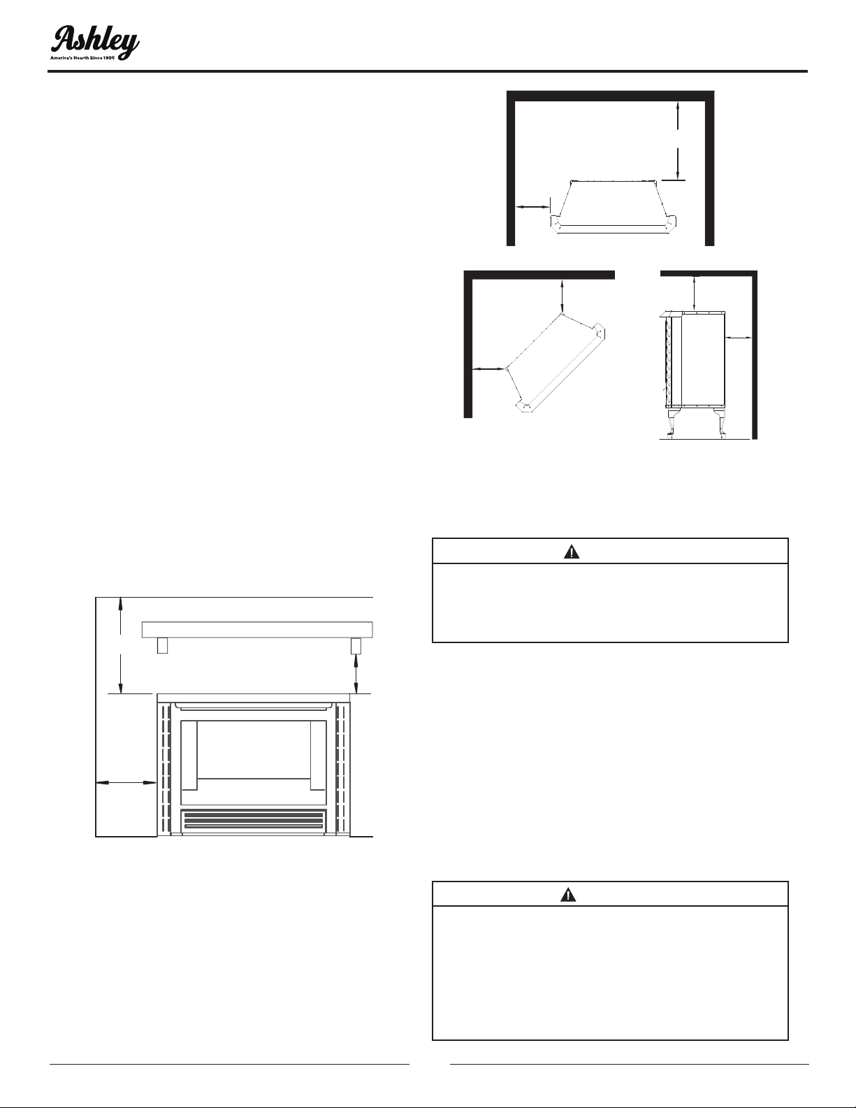
CLEARANCES (ZC)
To ensure a safe installation, the dimensions of the
following gures must be carefully observed.
20” MIN. CLEARANCE TO
MANTEL OR SUPPORTS
7” MIN.
CLEARANCE
TO SIDE WALL
SIDE WALL
CEILING
24” MIN.
FREESTANDING INSTALLATION
1. Determine the exact position of your gas heater.
NOTE: Due to high temperatures, this heater should
be located out of trafc areas and away from
furniture and draperies.
NOTE: For safe installation, the minimum clearances
must be met as shown.
NOTE:
DIMENSIONSSHOWNARE
MINIMUMCLEARANCETO
COMBUSTIBLEWALL.
STOVE
7”
1-1/2”
1-1/2”
24”
1-1/2”
1-1/2”
Attention: Maintain clearances listed above for any
required servicing and for proper operation of this
appliance
CAUTION:
THE INSTALLATION MUST CONFORM WITH
LOCAL CODES OR IN ABSENCE OF LOCAL
CODES, WITH NATIONAL FUEL GAS CODE,
ANSI Z223.1/NFPA54.
NOTE: See the “Gas Connection” section of this
manual for Gas Connection and Pressure Check.
1. Make sure you have the right valve for your
type of gas. Check the label on side of the valve.
Position logs as shown in the “Log Placement”
section of this manual. Position screen before
leaving the heater unattended.
This appliance is only for use with the type of gas
indicated on the rating plate. This appliance is not
convertible for use with other gases.
WARNING:
YOUNG CHILDREN SHOULD BE CAREFULLY
SUPERVISED WHEN THEY ARE IN THE SAME
ROOM WITH THE APPLIANCE. CHILDREN AND
ADULTS SHOULD BE ALERTED TO HAZARDS OF
HIGH SURFACE TEMPERATURE AND SHOULD
STAY AWAY TO AVOID BURNS OR CLOTHING
IGNITION.
INSTALLATION
© 2020 United States Stove Company
19
WARNING:
WHEN THE APPLIANCE IS INSTALLED
DIRECTLY ON CARPETING, TILE OR OTHER
COMBUSTIBLE MATERIAL, OTHER THAN
WOOD FLOORING, THE APPLIANCE SHALL
BE INSTALLED ON A METAL OR WOOD PANEL
EXTENDING FULL WIDTH AND DEPTH OF THE
APPLIANCE.
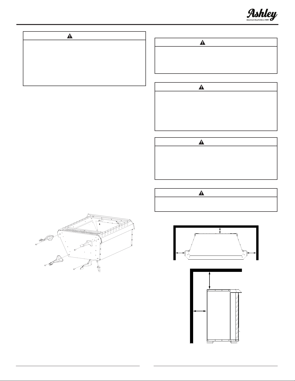
FREESTANDING LEGS INSTALLATION
To make this model free standing using cast legs,
follow the instructions below:
1. Place heater on its back.
2. Your heater is equipped with four leg mounting
nuts. Place a leg at each nut and secure leg with
bolts provided.
3. The legs are equipped with leveling bolts
needed for leveling adjustments.
4. Stand heater to the upright position. Place
heater in the desired location. At this point,
you may want to secure pedestal to oor with
screws or an “ell” bracket.
5. Hook up the gas supply line. Check for leaks with
mild soapy water (see “Installation Clearances
and Gas Connection” section of this manual).
ALCOVE INSTALLATION
READ ENTIRE MANUAL BEFORE INSTALLING
HEATER.
1. For clearances see below. The minimum must
be met.
2. For Installation and Gas Hookup Connection
(see the “Gas Connection” section of this
manual).
CAUTION:
THE INSTALLATION MUST CONFORM WITH
LOCAL CODES OR IN ABSENCE OF LOCAL
CODES, WITH NATIONAL FUEL GAS CODE,
ANSI Z223.1/NFPA54.
WARNING:
DO NOT USE THIS HEATER IF ANY PART HAS
BEEN UNDER WATER. IMMEDIATELY CALL A
QUALIFIED SERVICE TECHNICIAN TO INSPECT
ROOM HEATER AND TO REPLACE ANY PART
OF CONTROL SYSTEM AND GAS CONTROL
WHICH HAS BEEN UNDER WATER.
WARNING:
IMPROPER INSTALLATION, ADJUSTMENT,
ALTERATION, SERVICE OR MAINTENANCE
CAN CAUSE PROPERTY DAMAGE, PERSONAL
INJURY OR LOSS OF LIFE. REFER TO THIS
MANUAL.
WARNING:
ANY CHANGE TO THIS HEATER OR ITS
CONTROLS CAN BE DANGEROUS.
*ALL DIMENSIONS ARE MINIMUM TO COMBUSTIBLE WALL
1-1/2”
7” 7”
1-1/2”
24”
INSTALLATION
20
© 2020 United States Stove Company
VENTILATION
PRODUCING ADEQUATE AIR FOR
COMBUSTION AND VENTILATION
This section is for residential or manufactured
(mobile) installation. This heater shall not be
installed in unusually tight construction unless
provisions are adequate for combustion and
ventilation air.
NOTE: This heater shall not be installed in a room
or space unless the required volume of indoor
combustion air is provided by the method in
National Fuel Gas Code, ANSIZ223.1/NFPA 54, the
International Fuel Gas Code, or applicable codes.
National Fuel Gas Code, ANSI Z223.1/NFPA 54
denes unusually tight construction or unconned
space as a space whose volume is less than 50
cubic feet per 1,000 BTU per hour (4.8m 3 per kW)
of aggregate input rating of all appliances installed
in that space and an unconned space as a space
whose volume is not less than 50 cubic feet per
1,000 BTU per hour (4.8m 3 per kW) of aggregate
input rating of all appliances installed in that space.
Rooms communicating directly with space in
which appliances are installed, through openings
not furnished with doors, are considered a part of
unconned space. Unusually tight construction is
dened as construction where:
A. Walls and ceilings exposed to the outside
atmosphere have a continuous water vapor
retarder with a rating of 1 perm (6 x 10-11kg per
pa-sec-m2) or less with openings gasketed or
sealed.
B. Weatherstripping has been added on openable
windows and doors.
C. Caulking or sealants are applied to areas such
as joints around window and door frames,
between sole plates and oors, between
wall-ceiling joints, between wall panels, at
penetrations for plumbing, electrical and gas
lines and other openings.
NOTE: SOME AREAS IN THE UNITED STATES HAVE
HIGHER REQUIREMENTS FOR CUBIC FEET PER
1000 BTU/ HOUR INPUT. (EX. CINCINNATI, OHIO
CODES REQUIRE 70 CUBIC FEET). CHECK YOUR
LOCAL CODE BEFORE INSTALLATION
DETERMINING FRESH-AIR FLOW FOR
HEATER LOCATION
Determine if you have unusually tight construction
or unconned space. Use this worksheet to
determine if you have unusually tight construction
or unconned space. Space: Includes the room in
which you will install heater plus adjoining rooms
with doorless passageways or ventilation grills
between the rooms.
WARNING:
IF AREA IN WHICH HEATER MAY BE OPERATED
DOES NOT MEET THE REQUIRED VOLUME FOR
INDOOR COMBUSTION AIR, COMBUSTION
AND VENTILATION AIR SHALL BE PROVIDED
BY ONE OF THE METHODS DESCRIBED IN
NATIONAL FUEL GAS CODE, ANSI Z223.1/NFPA
54, THE INTERNATIONAL FUEL GAS CODE OR
APPLICABLE CODES.
WARNING:
IF AREA IN WHICH HEATER MAY BE
OPERATED IS SMALLER THAN THAT DEFINED
AS AN UNCONFINED SPACE OR IF BUILDING
IS OF UNUSUALLY TIGHT CONSTRUCTION,
PROVIDE ADEQUATE AIR FOR COMBUSTION
AND VENTILATION BY ONE OF THE METHODS
DESCRIBED IN NATIONAL FUEL GAS CODE,
ANSI Z223.1/NFPA 54 AIR FOR COMBUSTION
AND VENTILATION OR APPLICABLE LOCAL
CODES.
© 2020 United States Stove Company
21
1. Determine the volume of the space (length x width x height).
Length x Width x Height = _____________cu.ft.(volume of space)
EXAMPLE: 20 ft.(Length) x 16 ft.(Width) x 8 ft.(ceiling Height)= 2560 cu. ft. (volume of space)
If additional ventilation to adjoining room is supplied with grills or openings, add the volume of these
rooms to the total volume of the space.
2. Divide the space volume by 50 cubic feet to determine the maximum BTU/Hr the space can support.
_____________ (volume of space)/50 cu. ft. =maximum BTU/Hr the space can support
EXAMPLE: 2560 cu. ft. (volume of space /50 cu. Ft .= 51.2 or 51200 (maximum BTU/Hr the space can
support)
3. Add the BTU/Hr of all fuel burning appliances in the space.
Example:
Gas water heater 400000 BTU/Hr
Vent-free heater + 18000BTU/Hr
total = 58000 BTU/Hr
*Does not include direct-vent gas
appliances. Direct-vent draws
combustion air from outdoors and
vents to the outdoors.
Vent-free heater BTU/Hr __________ BTU/Hr
*Gas water heater BTU/Hr __________ BTU/Hr
Gas furnace BTU/Hr __________ BTU/Hr
Vented gas heater BTU/Hr __________ BTU/Hr
Gas replace logs BTU/Hr __________ BTU/Hr
Other gas appliance BTU/Hr +__________ BTU/Hr
Total =__________ BTU/Hr
4. Compare the maximum BTU/Hr the space can support with actual amount of BTU/Hr used.
_____________ BTU/Hr (maximum the space can support)
_____________ BTU/Hr (actual amount of BTU/Hr used)
Example: 51200 BTU/Hr (maximum the space can support)
58000 BTU/Hr (actual amount of BTU/Hr used)
Space in above example is unusually tight construction because actual BTU/Hr used is more than
maximum BTU/Hr the space can support. You must provide additional fresh air. Your options are as
follows:
A. Rework worksheet, adding space of an adjoining room. If extra space provides an unconned space,
remove door to adjoining room or add ventilation grills between rooms (see “Air For Combustion And
Ventilation Inside Building” section of this manual).
B. Vent room directly to the outdoors (see “Air For Combustion And Ventilation Outdoors” section of this
manual).
C. Install a lower BTU/Hr heater, if lower BTU/Hr size makes room unconned.
If actual BTU/Hr used is less than the maximum BTU/Hr the space can support, space is an unconned
space. You will need no additional fresh air ventilation.
WARNING: YOU MUST PROVIDE ADDITIONAL VENTILATION AIR IN UNUSUALLY TIGHT
CONSTRUCTION.
VENTILATION
22
© 2020 United States Stove Company
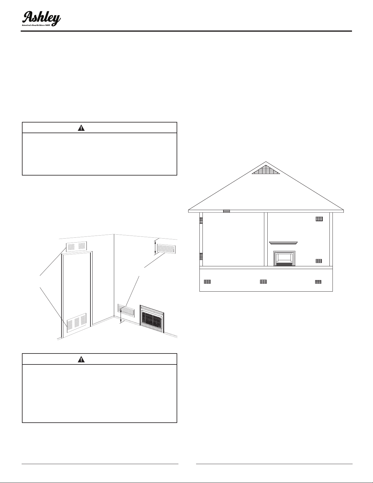
AIR FOR COMBUSTION AND
VENTILATION INSIDE BUILDING
This fresh air would come from an adjoining
unconned space. When venting to an adjoining
space, you must provide two permanent openings:
one within 12” of the ceiling and one within 12” of
the oor, on the wall connecting two spaces (see
Options 1 and 2 below). You can also remove the
door into the adjoining room as shown.
WARNING:
REWORK WORKSHEET, ADDING SPACE OF
ADJOINING UNCONFINED SPACE. COMBINED
SPACES MUST HAVE ADEQUATE AMOUNT OF
AIR TO SUPPLY ALL APPLIANCES IN BOTH
SPACES
NOTE: Each opening shall have a minimum free
area of 1 square inch per 1000 BTU’s per hour of the
total input ratings of all gas utilization equipment
in the conned space, but not less than 100 square
inches.
Ventilation Air From Inside Building
HOT AIR REGISTERS INTO
ADJOINING ROOMS
OPTION 2
HOT AIR REGISTERS INTO
ADJOINING ROOMS
OPTION 1
REMOVE DOOR
INTO ADJOINING
ROOM
OPTION 3
12”
12”
WARNING:
THIS HEATER MUST HAVE ADEQUATE AMOUNT
OF AIR FOR PROPER OPERATION. IF NOT,
POOR FUEL COMBUSTION COULD RESULT.
READ THE FOLLOWING INSTRUCTIONS TO
ENSURE PROPER AMOUNT OF AIR FOR THIS
AND OTHER FUEL-BURNING APPLIANCES IN
YOUR HOME.
AIR FOR COMBUSTION AND
VENTILATION OUTDOORS
Provide extra fresh air by using ventilation grills or
ducts. You must provide two permanent openings:
one within 12” of the ceiling and one within 12” of the
oor. Connect these items directly to the outdoors.
These spaces include attics and crawl spaces. Follow
the National Fuel Gas Code NFPA 54/ ANSI Z223.1,
Section 5.3, “Air For Combustion and Ventilation”
for the required size of ventilation grills or ducts.
IMPORTANT: Do not provide openings for inlet air
into attic if the attic has a thermostat-controlled
power vent. Heated air entering the attic will
activate the power unit.
Ventilated Attic
Outlet Air
Inlet Air
Ventilated
Crawl Space
To
Crawl
Space
To Attic
Outlet Air
Inlet Air
Ventilation Air From Outdoors
VENTILATION
© 2020 United States Stove Company
23
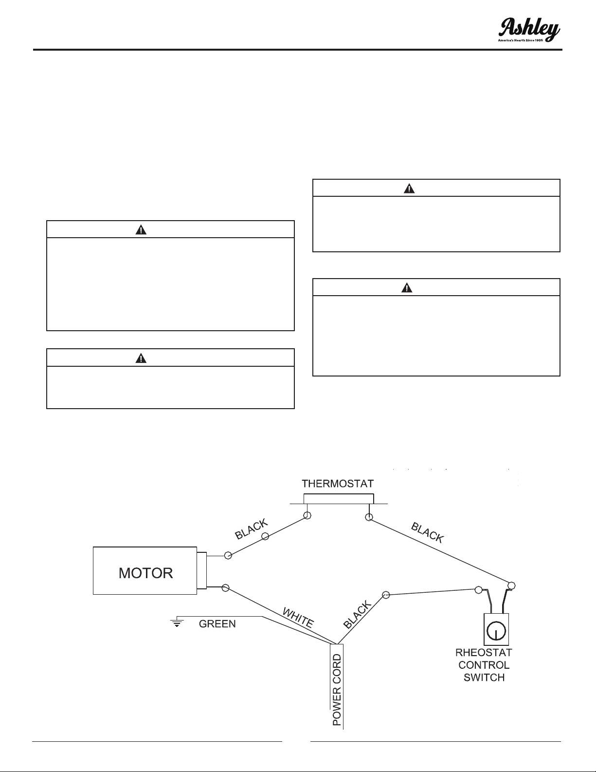
WIRING DIAGRAM
WHEN USED AS A HEATING APPLIANCE
HEAT OUTPUT
When used as a ventless heater, ue damper of a
solid-fuel burning non-combustible replace must
always be closed. The heat output is controlled
by the “On/Off” switch or wall thermostat when
using Millivolt Valve. The Vent-Free replace may
be installed where permitted by local, state and
city codes. In the absence of local codes, the latest
edition of the National Fuel Gas Code (ANSI Z223.1)
must be met.
WARNING:
CHILDREN AND ADULTS SHOULD BE
ALERTED TO HAZARDS OF HIGH SURFACE
TEMPERATURES AND SHOULD STAY AWAY
TO AVOID BURNS OR CLOTHING IGNITION.
YOUNG CHILDREN SHOULD BE CAREFULLY
SUPERVISED WHEN THEY ARE IN SAME ROOM
WITH APPLIANCE
WARNING:
DO NOT PLACE CLOTHING OR OTHER
FLAMMABLE MATERIAL ON OR NEAR
APPLIANCE.
Note: If any of the original wire as supplied with the
gas appliance must be replaced, it must be replaced
with a wire of at least a 105ºC temperature rating.
Note: Installation and repair should be done by
a qualied service person. This heater should be
inspected before use and at least annually by a
qualied service person. More frequent cleaning
may be required due to excessive lint from carpeting,
bedding material, etc. It is imperative that control
compartments and circulating air passageways of
heater be kept clean.
CAUTION:
LABEL ALL WIRES PRIOR TO DISCONNECTION
WHEN SERVICING CONTROLS. WIRING
ERRORS CAN CAUSE IMPROPER AND
DANGEROUS OPERATION.
WARNING:
ELECTRICAL GROUNDING INSTRUCTION:
HEATER IS EQUIPPED WITH A THREE-PRONG
PLUG FOR YOUR PROTECTION AGAINST
SHOCK HAZARD AND SHOULD BE PLUGGED
DIRECTLY INTO A PROPERLY GROUNDED
THREE-PRONG RECEPTACLE.
Note: 80442 blower motor. Rating: 120 volts/60hz/1.1
Amps.
Note: for convenience, allow licensed electrician to
install properly grounded 3-plug receptacle near
unit.
24
© 2020 United States Stove Company
MAINTENANCE
CLEANING
• The appliance must be turned “Off” before
cleaning inside the rebox (burn area), make sure
the pilot is “Off” completely and appliance has
cooled.
• All cleaning should be carried out when the
heater is cold. Limited cleaning is required with
normal use. Dusting front of the base, top of piezo
cover or control knob panel may be required
occasionally. Do not use cleaning uids to clean
logs or any other part of the heater.
• If ames show unusual shapes or behavior or if
the burner fails to ignite properly, burner holes
may require cleaning. If this occurs, contact your
nearest dealer to service heater.
• The heater can be cleaned by removing logs. Lift
logs gently, as not to damage ber pieces. The
logs have been spot glued in place for shipping,
use caution when removing. Lift each log by
holding it carefully at each end. Use a vacuum
cleaner to remove dust and loose particles from
the base, logs and around the burner and ODS/
Pilot. Gloves are recommended to prevent bers
from breaking the skin. If the skin is broken, clean
with soap and water.
CAUTION:
BEFORE CLEANING OR MOVING THESE LOGS
OR OTHER PARTS OF HEATER, BE SURE TO
READ ABOVE SECTIONS ON “IMPORTANT
SAFEGUARDS.”
WARNING:
FAILURE TO KEEP THE PRIMARY AIR
OPENINGS(S) OF THE BURNER(S) CLEAN MAY
RESULT IN SOOTING AND PROPERTY DAMAGE.
For Parts Assistance Call: 800-750-2723 Ext 5051 or Email: parts@usstove.com
The information in this owner’s manual is specic to your unit. When ordering replacement parts the
information in this manual will help to ensure the correct items are ordered. Before contacting customer
service write down the model number and the serial number of this unit. That information can be found on
the certication label attached to the back of the unit. Other information that may be needed would be the
part number and part description of the item(s) in question. Part numbers and descriptions can be found
in the “Repair Parts” section of this manual. Once this information has been gathered you can contact
customer service by phone 1-800-750-2723 Ext 5051 or Email parts@usstove.com.
Model Information
Model Number
Serial Number
HOW TO ORDER REPAIR PARTS
© 2020 United States Stove Company
25
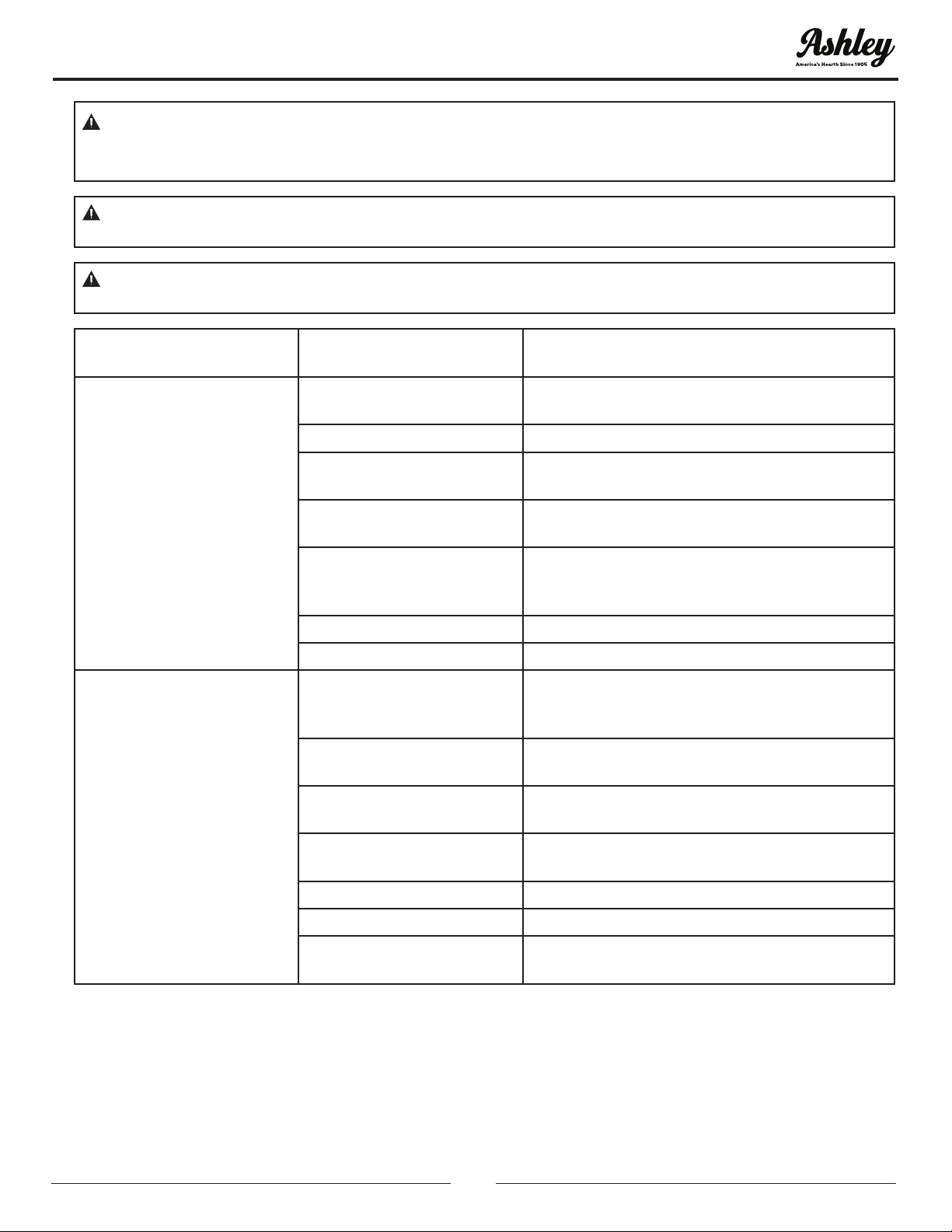
OBSERVED
PROBLEM POSSIBLE
CAUSE
SOLUTION
Igniter button is pressed no
spark at ODS/Pilot
Igniter electrode positioned
incorrectly
Replace igniter
Igniter electrode broken Replace igniter
Igniter electrode not
connected to igniter cable
Reconnect igniter cable
Igniter cable pinched or
wet
Free igniter cable if pinched by any metal or
tubing. Keep igniter cable dry
Piezo igniter nut is loose
Tighten nut holding piezo igniter to heater
cabinet. Nut is located inside heater cabinet at
top
Broken igniter cable Replace igniter cable
Bad piezo igniter Replace piezo igniter
Igniter button is pressed
Spark at ODS/Pilot No
Ignition
Gas supply turned off or
manual shutoff valve is
closed
Turn on gas supply or open manual shutoff
valve
Control knob not in
“PILOT”position
Turn control knob to “PILOT” position
Control knob not pressed
in while in “PILOT” position
Press in control knob while in “PILOT” position
Air in gas lines when
installed
Continue to hold down control knob. Repeat
igniting operation until air is removed.
Depleted gas supply Contact local propane gas company
ODS/Pilot is clogged Clean ODS/Pilot or replace ODS/Pilot assembly
Gas regulator setting is not
correct
Replace gas regulator
CAUTION: INSTALLATION AND REPAIR SHALL ONLY BE DONE BY A QUALIFIED SERVICE PERSON.
THE FIREPLACE SHOULD BE INSPECTED BEFORE USE BY A QUALIFIED SERVICE PERSON. IT IS
REQUIRED TO BE INSPECTED AT LEAST ONCE A YEAR BY A PROFESSIONAL SERVICE PERSON.
CAUTION: NEVER USE A WIRE, NEEDLE OR SIMILAR OBJECT TO CLEAN ODS/PILOT. THIS CAN
DAMAGE ODS/PILOT.
WARNING: TURN OFF, UNPLUG HEATER AND LET COOL BEFORE SERVICING. ONLY A QUALIFIED
SERVICE PERSON SHOULD SERVICE AND REPAIR HEATER.
TROUBLESHOOTING
26
© 2020 United States Stove Company
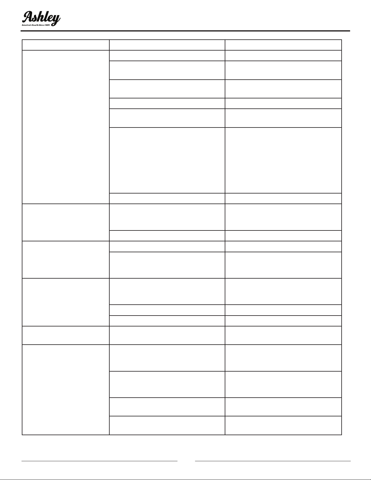
OBSERVED PROBLEM POSSIBLE CAUSE SOLUTION
ODS/PILOT lights but ame
goes out when control
knob is released
Control knob is not fully pressed in Press control knob completely
Control knob not pressed in long
enough
After ODS/Pilot lights keep control
knob pressed thirty (30) seconds
Safety interlock system has been
triggered (if equipped)
Wait one (1) minute for safety
interlock system to reset
Manual shutoff valve not fully open Fully open manual shutoff valve
Thermo-couple connection loose at
control valve
Hand tighten until snug, then tighten
1/4 turn
Pilot ame not touching thermo-
couple, which allows thermo-couple
to cool, causing pilot ame to go out.
This problem can be caused by one
or both of the following:
A) Low gas pressure
B) Dirty or partially clogged ODS/
Pilot
A) Contact local propane gas
company
B) Clean ODS/Pilot (see Cleaning and
Maintenance section of this manual)
or replace ODS/Pilot assembly
Control valve damaged Replace valve control
Burner does not light after
ODS/ Pilot is lit
Burner orice is clogged
Clean burner (see Cleaning and
Maintenance section of this manual)
or replace burner orice
Inlet gas pressure is too low Contact local propane gas company
Delayed ignition of burner
Manifold pressure is too low Contact local propane gas company
Burner orice is clogged
Clean burner (see Cleaning and
Maintenance section of this manual)
or replace burner orice
Burner backring during
combustion
Burner orice is clogged ordamaged
Clean burner (see Cleaning and
Maintenance section of this manual)
or replace burner orice
Burner damaged Replace burner
Gas regulator defective Replace gas regulator
Slight smoke or odor
during initial operation
Residues from manufacturing
process
Problem will stop after a few hours of
operation
Heater produces a whistling
noise when burner is lit
Turning control knob to “HI” position
when burner is cold (if equipped
with this type of valve)
Turn control knob to “LOW” position
and allow to warm
Air in gas line
Operate burner until air is removed
from line. Call local propane company
to check gas line
Air passageways on heater blocked
Observe minimum installation
clearances
Dirty or partially clogged burner
orice
Clean burner or replace orice
TROUBLESHOOTING
© 2020 United States Stove Company
27
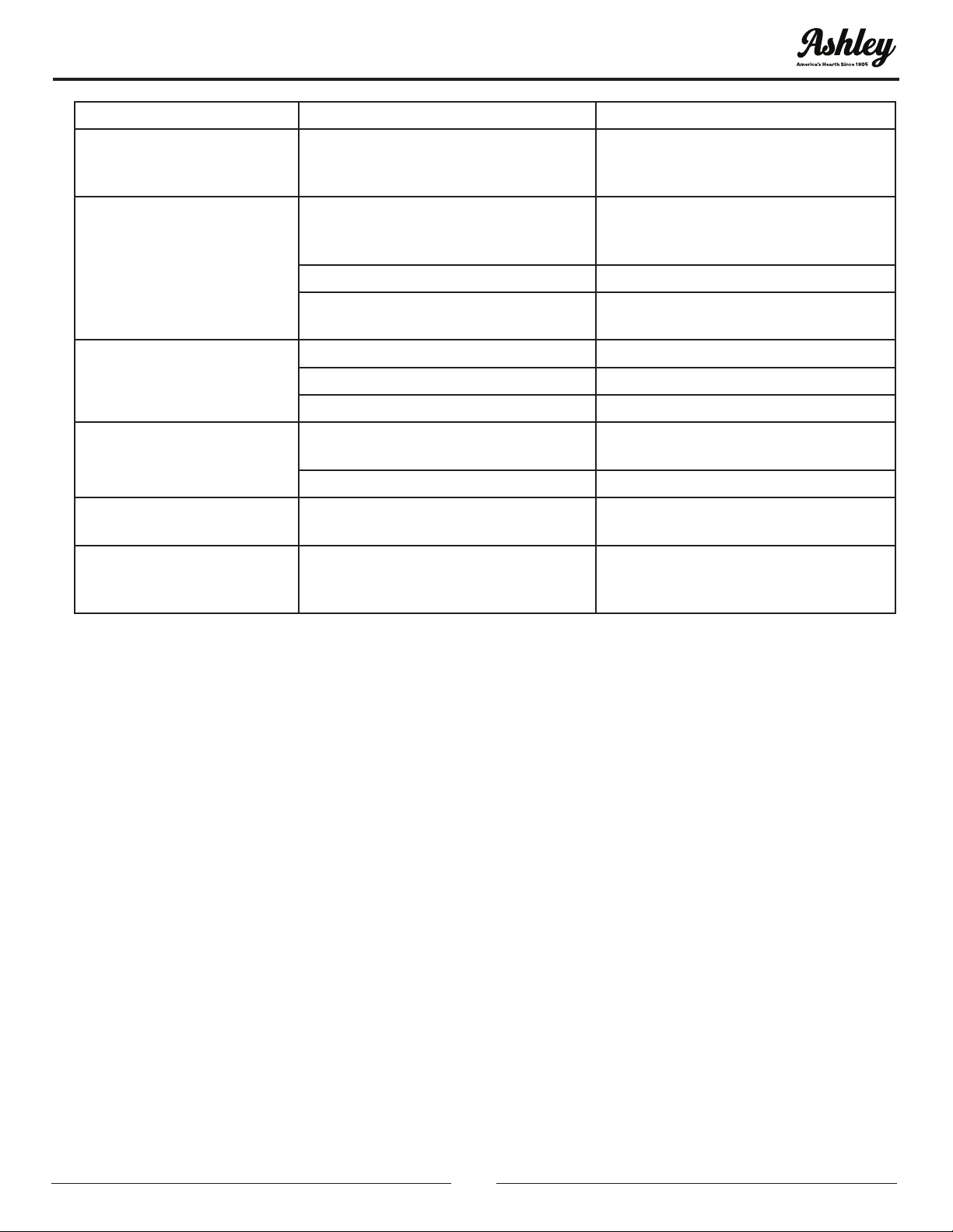
OBSERVED PROBLEM POSSIBLE CAUSE SOLUTION
Heater produces a clinking/
ticking noise just after
burner is lit r shut off
Metal expands while heating or
contracts while cooling
This is common with most heaters. If
noise is excessive, contact a qualied
service person
Heater produces unwanted
odors
Heater burning vapors from paint,
hairspray, glues, etc. (see Important
above)
Ventilate room. Stop using odor
causing products while heater is
running
Low fuel supply Rell supply tank
Gas leak (see WARNING above)
Locate and control all leaks (see
Checking Gas Connections)
Heater shuts off in use
(ODS operates)
Not enough fresh air is available Open window/door for ventilation
Low line pressure Contact local propane co.
ODS/Pilot is partially clogged Clean ODS/Pilot
Gas odor even when control
knob is in OFF position
Gas leak see WARNING above).
Locate and correct all leaks (see
Checking Gas Connections)
Control valve defect Replace control valve
Gas odor during
combustion
Foreign matter between control
valve and burner
Remove foreign matter from gas
tubing
Gas leak (see WARNING above)
Locate and correct all leaks (see
Checking
Gas Connections)
TROUBLESHOOTING
28
© 2020 United States Stove Company
1
4
3
2
8
7
9
11
5
6
10
12
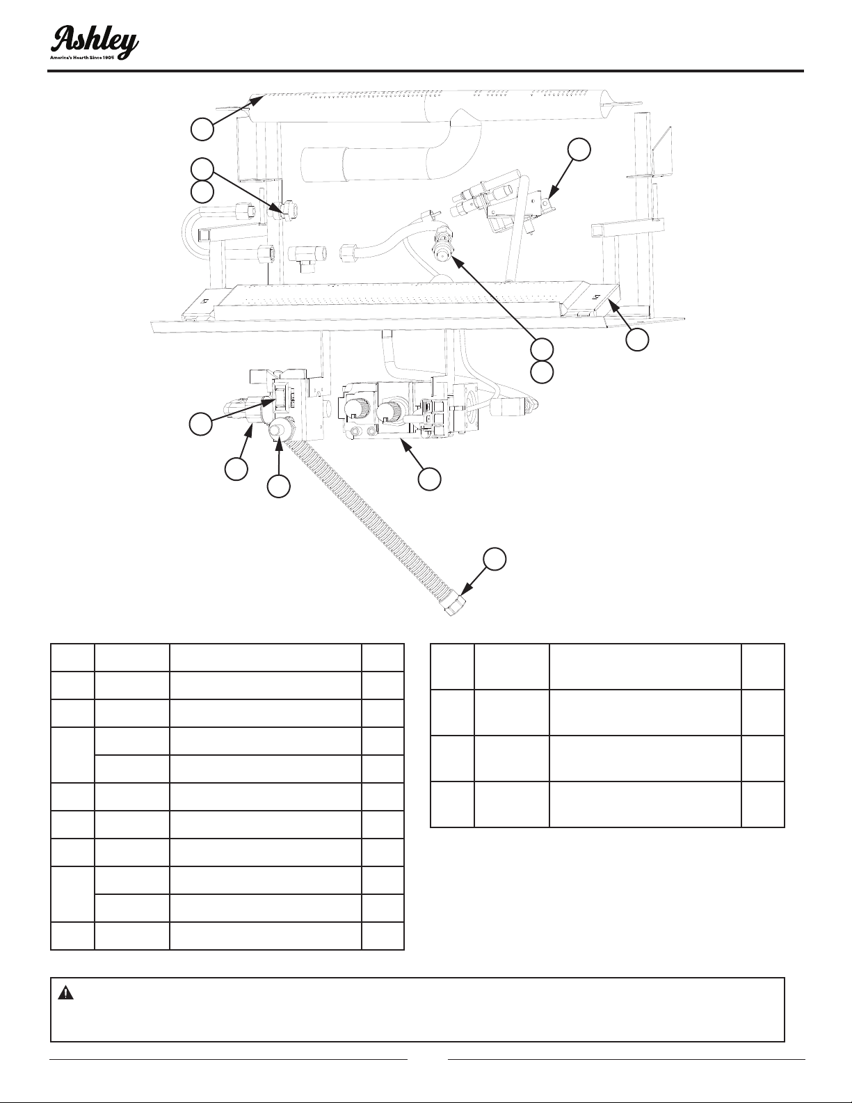
Key Part # Description Qty
1 81212.2 Flex Tube 1
2 89761 Piezo Ignitor 1
3
81202 Control Valve (LP) 1
81198 Control Valve (NAT) 1
4 81212-6 Bottom Burner 1
5 81212.8 On/Off Valve 1
6 81212.14 (Auto/Off/Auto) Switch 1
7
89921 Pilot Assembly (NAT) 1
89922 Pilot Assembly (LP) 1
8 81212-11 Top Burner 1
9 81212.16
Upper Burner Orices
(Nat) #46
1
10 81212.20
Upper Burner Orices
(LP) #56
1
11 81212.17
Lower Burner Orices
(NAT) #48
1
12 81212.21
Lower Burner Orices
(LP) #55
1
To order parts:
Call 1-800-750-2723 Ext 5051 or
Email to: parts@usstove.com
REPLACEMENT PARTS
WARNING: FAILURE TO POSITION THE PARTS IN ACCORDANCE WITH THESE DIAGRAMS OR
FAILURE TO USE ONLY PARTS SPECIFICALLY APPROVED WITH THIS APPLIANCE MAY RESULT IN
PROPERTY DAMAGE OR PERSONAL INJURY.