Safety • Assembly • Operation • Adjustment • Maintenance • Troubleshooting • Warranty
OF A O AL
Shift=On-The=Go'" Lawn Tractor -- Models 760=779
iMPORTANT
READ SAFETY RULES AND iNSTRUCTiONS CAREFULLY BEFORE OPERATION
Warning: Thisunit is equippedwithan internalcombustionengineandshouldnot beusedon or nearany unimprovedforest-covered,brush-
coveredor grass-coveredland unlesstheengine'sexhaustsystemis equippedwitha sparkarrestermeetingapplicablelocalor statelaws(if any).
If a sparkarresteris used,it shouldbemaintainedineffectiveworkingorderby the operator.In theStateof Californiathe aboveis requiredbylaw
(Section4442of the CaliforniaPublicResourcesCode).Otherstatesmayhavesimilarlaws.Federallaws applyon federallands.A sparkarrester
for the muffleris availablethroughyour nearestengineauthorizedservicedealeror contactthe servicedepartment,RO.Box361131Cleveland,
Ohio44136-0019.
PRINTEDIN U.S.A.
MTD LLC, P.O. BOX 361131 CLEVELAND, OHIO 44136-0019
FORMNO.769-01598C
01/22/2007

This Operator's Manual is an important part of your new lawn tractor, it will help you assemble,
prepare and maintain the unit for best performance. Please read and understand what it says.
Table of Contents
Slope Gauge ........................................................ 3
Safe Operation Practices ................................... 4
Setting UpYour Lawn Tractor ............................ 8
Operating Your Lawn Tractor ........................... 12
Adjusting Your Lawn Tractor ............................ 20
Maintaining Your Lawn Tractor ........................ 22
Off-Season Storage / Attachments ................. 28
Safety Labels .................................................... 29
Trouble Shooting .............................................. 30
Warranty .............................................. Back Page
Finding and Recording Model Number
BEFOREYOU STARTASSEMBLING YOURNEW EQUIPMENT,
please locate the model plate on the equipment and copy the
informationto the sample model plate providedto the right. You
can locate the model plate by looking beneath the seat.
This information will be necessary to use the manufacturer's web
site and/or obtain assistance from the Customer Support Depart-
ment or an authorized service dealer.
Model Number
®
www.mtd prod ucts.corn
Serial Number
MTD LLC
P.O. BOX 361131
CLEVELAND, OH 44136
330=220=4683
800=800=731 0 j
Customer Support
Please do IVOTreturn the unit to the retailer from which it was
purchased, without first contacting Customer Support.
If you have difficulty assembling this product or have any questions regardingthe controls, operation,or maintenanceof this
unit, you can seek help from the experts. Choose from the options below:
1. Visit www.mtdproducts.com.
2. Phone a Customer Support Representative at 1 (800) 800-7310.
3. The engine manufacturer is responsiblefor all engine-relatedissues with regardsto performance, power-rating,specifica-
tions, warranty and service. Pleaserefer to the engine manufacturer'sOwner's/Operator's Manual, packed separatelywith
your unit.
2
>:.
G.)
o9
(13
(13
O
O
C
::>.,
E
c_
O
G.)
o6
_-- (13
co .oo
G.) o9
o -_
O9 C:_
G.) O9
C C
_ o
(13
-_ o_
O
C
(13
c_
0
o3
0
C
co 0
_ a
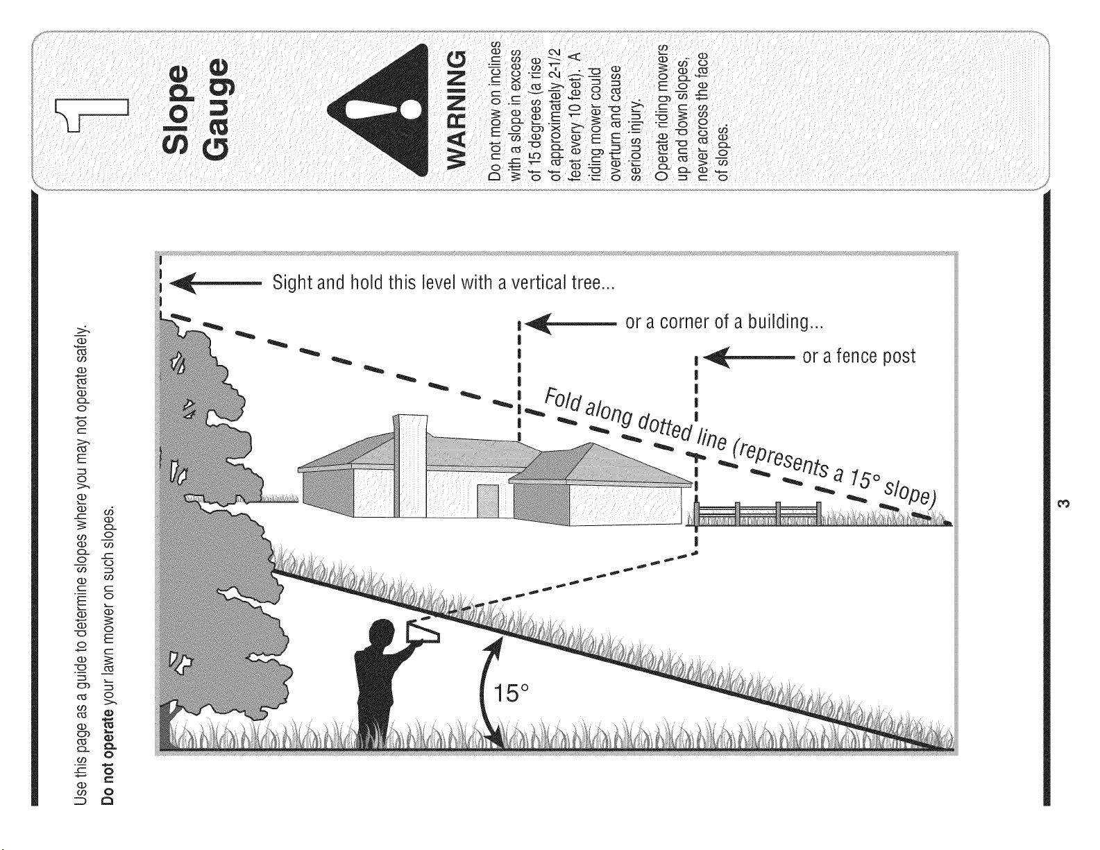
Sight and h01dthis level with a vertical tree..,
m_,_ or a corner of a building...
I
I
__ or a fence post
I
i i
do;
-- fine (repros
I _ _ er_ts a 15o
15°
_0
Operation
WARNING
This symbol points
out important safety
instructionswhich, if
notfollowed, could
i endangerthe personal
safety and/or property
ofyourself and others.
I Readand follow all
i instructions in this man-
i ual before attempting to
i operatethis machine.
Failureto comply with
these instructions may
result in personal injury.
i Whenyou see this
symbol.
i HEED ITS WARNING
Your
i Responsibility
Restrictthe use
of this power machine
I to persons who read,
understand
and follow the warnings
and instructions
in this manual
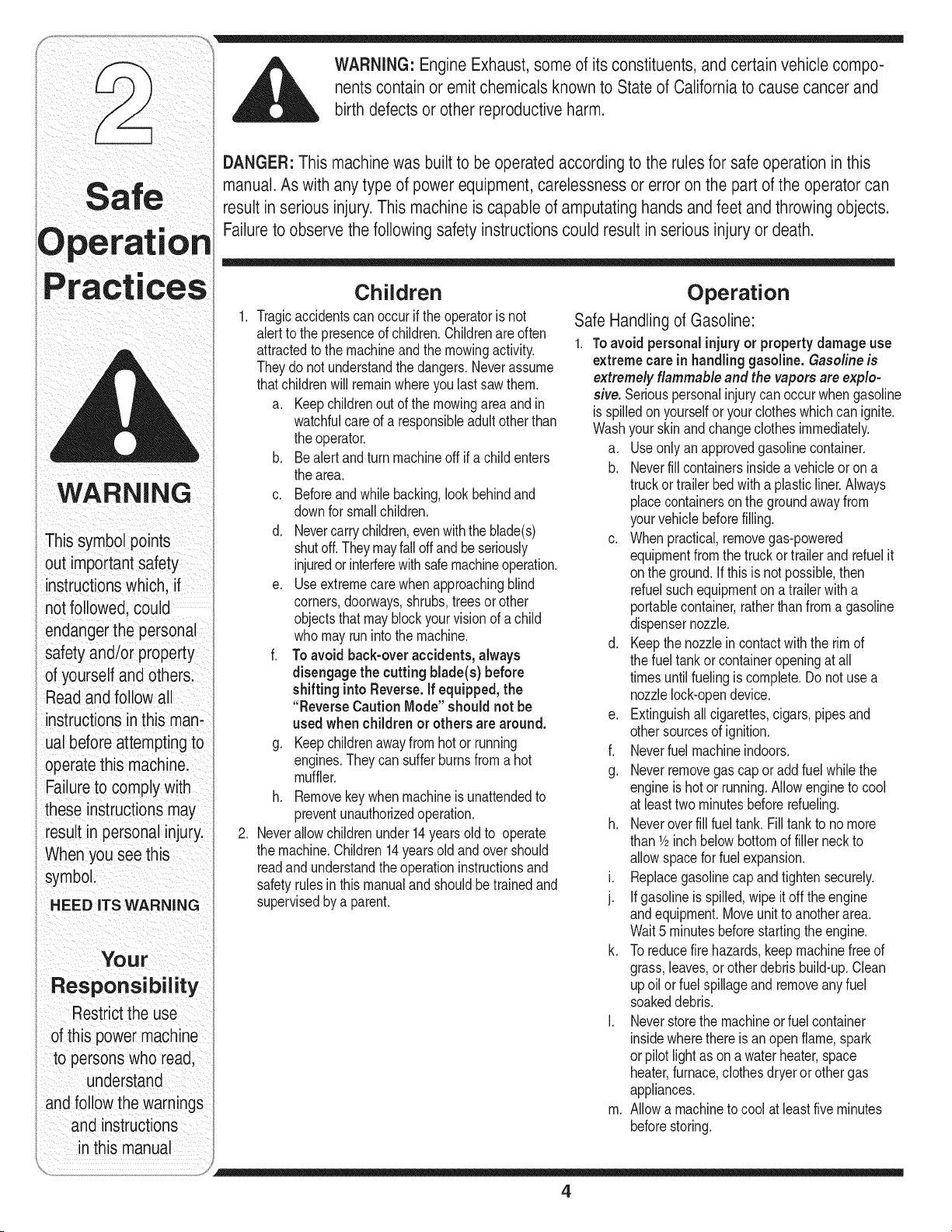
WARNING: Engine Exhaust,some of its constituents, and certain vehicle compo-
nents contain or emit chemicals knownto State of Californiato cause cancer and
birth defects or other reproductiveharm.
DANGER: This machine was built to be operated according to the rules for safe operation in this
manual. As with any type of power equipment, carelessness or error on the part of the operator can
result in serious injury. This machine is capable of amputating hands and feet and throwing objects.
Failureto observe the following safety instructionscould result in serious injury or death.
Children
1. Tragicaccidentscanoccurif the operatoris not
alertto the presenceof children.Childrenareoften
attractedto themachineandthe mowingactivity.
Theydo not understandthe dangers.Neverassume
thatchildrenwill remainwhereyou last sawthem.
a. Keepchildrenout of the mowingareaandin
watchfulcare of a responsibleadultother than
the operator.
b. Bealert andturnmachineoff ifa childenters
the area.
c. Beforeandwhile backing,lookbehindand
downfor smallchildren.
d. Nevercarrychildren,evenwith the blade(s)
shutoff.Theymayfalloffandbeseriously
injuredorinterferewithsafemachineoperation.
e. Useextremecarewhenapproachingblind
corners,doorways,shrubs,trees or other
objectsthat may blockyourvision of a child
whomayrunintothe machine.
f. To avoid back-over accidents, always
disengagethe cuttingblade(s) before
shiftinginto Reverse.If equipped,the
"Reverse CautionMode"shouldnot be
used whenchildrenor others are around.
g. Keepchildrenawayfromhotor running
engines.Theycan sufferburnsfroma hot
muffler.
h. Removekeywhenmachineis unattendedto
preventunauthorizedoperation.
2. Neverallowchildrenunder14yearsoldto operate
the machine.Children14years old and overshould
readand understandthe operationinstructionsand
safetyrulesinthis manualand shouldbetrainedand
supervisedbya parent.
Operation
Safe Handling of Gasoline:
1. Toavoid personalinjuryor propertydamageuse
extremecare inhandlinggasoline.Gasolineis
extremely flammableand the vapors areexplo-
sive. Seriouspersonalinjurycan occurwhengasoline
isspilledonyourselfor yourclotheswhichcan ignite.
Washyourskinandchangeclothesimmediately.
a. Useonlyanapprovedgasolinecontainer.
b. Neverfill containersinsidea vehicleor on a
truckor trailerbed with a plasticliner.Always
placecontainersonthe groundawayfrom
yourvehiclebeforefilling.
c. Whenpractical,removegas-powered
equipmentfromthe truckor trailerand refuelit
onthe ground.Ifthis isnotpossible,then
refuelsuchequipmenton a trailerwitha
portablecontainer,ratherthan froma gasoline
dispensernozzle.
d. Keepthe nozzlein contactwith the rimof
the fueltankor containeropeningat all
timesuntilfuelingiscomplete.Donot usea
nozzlelock-opendevice.
e. Extinguishallcigarettes,cigars,pipesand
othersourcesof ignition.
f. Neverfuel machineindoors.
g. Neverremovegas cap oraddfuel whilethe
engineishot or running.Allowengineto cool
at leasttwominutesbeforerefueling.
h. Neveroverfill fuel tank.Fill tankto nomore
than1/2inchbelowbottomof filler neckto
allowspacefor fuel expansion.
i. Replacegasolinecapandtighten securely.
j. If gasolineis spilled,wipe it off theengine
andequipment.Moveunit to anotherarea.
Wait5 minutesbeforestartingtheengine.
k. Toreducefirehazards,keepmachinefreeof
grass,leaves,or otherdebris build-up.Clean
upoil or fuel spillageand removeanyfuel
soakeddebris.
I. Neverstorethe machineor fuel container
insidewherethere is an open flame,spark
orpilot lightas on a waterheater,space
heater,furnace,clothesdryeror other gas
appliances.
m. Allowa machineto cool at leastfiveminutes
beforestoring.
4
GeneralOperation:
1. Read,understand,andfollowall instructionsonthe
machineandin the manual(s)beforeattemptingto
assembleandoperate.Keepthismanualina safe
placefor futureandregularreferenceandfor ordering
replacementparts.
2. Be familiarwith allcontrolsandtheir properoperation.
Knowhow to stopthe machineanddisengagethem
quickly.
3, Neverallowchildrenunder 14yearsold to operate
this machine.Children14years old and overshould
readandunderstandthe operationinstructionsand
safetyrulesinthis manualand shouldbetrainedand
supervisedby a parent.
4. Neverallowadults to operatethis machinewithout
properinstruction.
5. To helpavoidbladecontactora thrownobject injury,
keep bystanders,helpers,childrenand petsat least
75feet fromthe machinewhileit is in operation.Stop
machineif anyoneentersthearea.
6. Thoroughlyinspecttheareawheretheequipmentis to
be used. Removeall stones,sticks,wire,bones,toys,
andotherforeignobjectswhichcouldbe pickedup
andthrownbythe blade(s).Thrownobjectscancause
seriouspersonalinjury.
7. Planyourmowingpatternto avoiddischargeof
materialtowardroads,sidewalks,bystandersandthe
like.Also,avoiddischargingmaterialagainstawall or
obstructionwhichmaycausedischargedmaterialto
ricochetbacktowardthe operator.
8. Alwayswear safetyglassesor safetygogglesduring
operationandwhile performingan adjustmentor
repairto protectyoureyes.Thrownobjectswhich
ricochetcancause seriousinjuryto the eyes.
9. Wearsturdy,rough-soledworkshoesandclose-fitting
slacksandshirts.Loosefittingclothesandjewelry
can becaughtinmovableparts.Neveroperatethis
machinein barefeet or sandals.
10.Beawareof the mowerand attachmentdischarge
directionanddo not pointit at anyone.Donot operate
the mowerwithoutthe dischargecoverorentiregrass
catcherin its properplace.
11.Donot put handsor feetnearrotatingpartsor under
the cuttingdeck. Contactwiththe blade(s)can
amputatehandsandfeet.
12.A missingor damageddischargecovercan cause
bladecontactorthrownobjectinjuries.
13.Stop the blade(s)whencrossinggraveldrives,walks,
or roadsand whilenot cuttinggrass.
14.Watchfor traffic whenoperatingnearor crossing
roadways.Thismachineis not intendedfor useon
anypublic roadway.
15.Do notoperatethe machinewhileunderthe influ-
enceof alcoholordrugs.
16.Mowonly in daylightor goodartificiallight.
17.Nevercarrypassengers.
18.Disengageblade(s)beforeshiftinginto reverse.
Backupslowly.Alwayslookdownand behindbefore
andwhilebackingto avoida back-overaccident.
19.Slowdownbeforeturning.Operatethe machine
smoothly.Avoiderraticoperationandexcessive
speed.
20.Disengageblade(s),setparkingbrake,stopengine
andwaituntilthe blade(s)cometo a completestop
beforeremovinggrasscatcher,emptyinggrass,
uncloggingchute,removingany grassor debris,or
makinganyadjustments.
21.Neverleavea runningmachineunattended.Always
turnoff blade(s), placetransmissionin neutral,set
parkingbrake,stopengineand removekey before
dismounting.
22.Useextracare whenloadingorunloadingthe
machineintoa traileror truck. This unit shouldnot
bedrivenupor downramp(s),becausethe unit
couldtip over,causingseriouspersonalinjury.The
unit mustbepushedmanuallyon ramp(s)to load or
unloadproperly.
23.Mufflerand enginebecomehotandcan causea
burn.Do nottouch.
24.Checkoverheadclearancescarefullybeforedriving
underlowhangingtreebranches,wires,dooropen-
ingsetc.,wheretheoperatormaybe struckor pulled
fromthe unit,whichcouldresultinseriousinjury.
25.Disengageallattachmentclutches,depressthe
brakepedalcompletelyandshift into neutralbefore
attemptingto startengine.
26.Yourmachineisdesignedto cut normalresidential
grassof a heightno morethan 10".Do notattemptto
mowthroughunusuallytall,dry grass(e.g.,pasture)
or pilesof dry leaves.Drygrass or leavesmay
contactthe engineexhaustand/orbuildup on the
mowerdeckpresentinga potentialfire hazard.
27.Useonlyaccessoriesand attachmentsapprovedfor
thismachinebythe machinemanufacturer.Read,
understandandfollowall instructionsprovidedwith
the approvedaccessoryor attachment.
28.Dataindicatesthat operators,age 60 yearsand
above,are involvedin a largepercentageof riding
mower-relatedinjuries.Theseoperatorsshould
evaluatetheirabilityto operatethe ridingmower
safelyenoughto protectthemselvesandothersfrom
seriousinjury.
29.If situationsoccurwhich are not coveredin this
manual,usecareandgoodjudgment.Contactyour
customerservicerepresentativefor assistance.
!i!i ¸¸¸:¸/: :!i¸ ¸¸¸ : :
WARNING
This symbol points
out important safety
instructions which, if
not followed, could
endanger the personal
safety and/or property
of yourself and others.
Readand follow all
instructions inthis man-
ual before attempting to
operate this machine.
Failureto comply with
these instructionsmay
result in personal injury.
When you see this
symbol.
HEED ITS WARNING
Your
Responsibility
Restrictthe use
of this power machine
to persons who read,
understand
and follow the warnings
and instructions
in this manual
5
Operation
This symbol points
out important safety
instructions which, if
notfollowed, could
endangerthe personal
i safety and/or property
of yourself and others.
Read and follow all
=nstructionsin this man-
ual before attempting to
I operate this machine.
I Failureto comply with
i these instructions may
i result in personal injury.
When you see this
symbol.
HEED ITS WARNING
Your
Responsibility
Restrictthe use
of this power machine
to persons who read,
understand
and follow the warn=ngs
and instructions
in this manual
Slopesare a majorfactor relatedto loss of controland
tip-overaccidentswhichcan resultin severeinjuryor
death.All slopesrequireextracaution.If youcannot
backupthe slopeor if youfeel uneasyon it, do notmow
it.
Foryour safety,usethe slopegaugeincludedas partof
thismanualto measureslopesbeforeoperatingthis unit
ona slopedor hillyarea. Ifthe slopeis greaterthan 15
degreesas shownon theslopegauge,do notoperate
thisunit onthatareaor seriousinjurycouldresult.
DO:
1. Mowupanddownslopes,notacross. Exercise
extremecautionwhenchangingdirectionon slopes.
2. Watchfor holes,ruts,bumps,rocks,or other hidden
objects.Uneventerraincouldoverturnthe machine.
Tallgrasscan hideobstacles.
3. Useslowspeed.Choosea low enoughspeed
settingso thatyouwill not haveto stopor shift while
onthe slope.Tiresmaylosetractiononslopeseven
thoughthe brakesarefunctioningproperly.Always
keepmachineingearwhengoingdown slopesto
takeadvantageof enginebrakingaction.
4. Followthe manufacturer'srecommendationsfor
wheelweightsor counterweightsto improvestability.
5. Useextracare withgrasscatchersorotherat-
tachments.Thesecanchangethe stabilityof the
machine.
6. Keepall movementon the slopesslowand gradual.
Do not makesuddenchangesin speedor direction.
Rapidengagementor brakingcouldcausethe front
of the machineto liftand rapidlyflip overbackwards
whichcouldcauseseriousinjury.
7. Avoidstartingor stoppingon a slope.If tireslose
traction,disengagethe blade(s)andproceedslowly
straightdownthe slope.
Do Not:
1. Do notturn on slopesunlessnecessary;then,turn
slowlyandgraduallydownhill,if possible.
2. Do not mowneardrop-offs,ditchesor embankments.
Themowercouldsuddenlyturnoverif a wheel is over
the edgeof a cliff, ditch,or if an edge cavesin.
3. Do nottry to stabilizethe machineby puttingyourfoot
onthe ground.
4. Do not usea grasscatcheron steep slopes.
5. Do not mowonwetgrass. Reducedtractioncould
causesliding.
6. Do not shiftto neutralandcoastdownhill.Over-speed-
ingmaycausethe operatorto losecontrol of the
machineresultingin seriousinjuryor death.
7. Do nottow heavypull behindattachments(e.g.loaded
dumpcart, lawnroller,etc.)on slopesgreaterthan
5 degrees.Whengoingdown hill,the extra weight
tendsto pushthe tractorandmaycauseyou to loose
control.(e.g.tractormayspeedup, brakingand steer-
ingabilityarereduced,attachmentmayjack-knifeand
causetractorto overturn).
Towing:
1. Towonlywitha machinethat hasa hitchdesignedfor
towing.Donot attachtowedequipmentexceptat the
hitchpoint.
2. Followthe manufacturersrecommendationfor weight
limitsfor towedequipmentandtowingon slopes.
3. Neverallowchildrenor othersin oron towedequip-
ment.
4. Onslopes,the weightof the towedequipmentmay
causelossof tractionandlossof control.
5. Travelslowlyandallowextradistanceto stop.
6. Do not shiftto neutralandcoastdownhill.
6
Service
1. Neverrunanengineindoorsorina poorlyventilated
area. Engineexhaustcontainscarbonmonoxide,an
odorless,anddeadlygas.
2. Beforecleaning,repairing,or inspecting,makecertain
the blade(s)andall movingparts havestopped.
Disconnectthe sparkplugwireandgroundagainstthe
engineto preventunintendedstarting.
3. Periodicallycheckto make surethe bladescome to
completestopwithinapproximately(5) five seconds
afteroperatingthe bladedisengagementcontrol.Ifthe
bladesdo notstop within thethis timeframe,yourunit
shouldbe servicedprofessionallyby an authorized
MTDServiceDealer.
4. Checkbrakeoperationfrequentlyas it is subjectedto
wearduringnormaloperation.Adjustand serviceas
required.
5. Checkthe blade(s)andenginemountingboltsat
frequentintervalsfor propertightness.Also,visually
inspectblade(s)for damage(e.g.,excessivewear,
bent,cracked). Replacethe blade(s)withtheoriginal
equipmentmanufacturer's(O.E.M.)blade(s)only,
listedinthis manual."Useof partswhich do not meet
the originalequipmentspecificationsmayleadto
improperperformanceandcompromisesafety!"
6. Mowerbladesare sharp.Wrapthe bladeor wear
gloves,anduseextracautionwhenservicingthem.
7. Keepall nuts, bolts,and screwstight to be surethe
equipmentis insafeworkingcondition.
8. Nevertamperwith the safety interlocksystemor other
safetydevices.Checktheir properoperationregularly.
9. Afterstrikingaforeignobject,stopthe engine,
disconnectthe sparkplugwire(s)andgroundagainst
the engine.Thoroughlyinspectthe machinefor any
damage.Repairthe damagebeforestartingand
operating.
10.Neverattemptto makeadjustmentsor repairsto the
machinewhilethe engineisrunning.
11.Grasscatchercomponentsandthe discharge
coveraresubjectto wearanddamagewhich could
exposemovingpartsor allowobjectsto be thrown.
Forsafetyprotection,frequentlycheckcomponents
andreplaceimmediatelywithoriginalequipment
manufacturer's(O.E.M.)partsonly,listedinthis
manual."Useof parts which do not meetthe original
equipmentspecificationsmayleadto improper
performanceandcompromisesafety!"
12.Do notchangethe enginegovernorsettingsor
over-speedthe engine.Thegovernorcontrolsthe
maximumsafeoperatingspeedof the engine.
13.Maintainor replacesafetyandinstructionlabels,as
necessary.
14.Observeproperdisposallawsand regulationsfor
gas,oil,etc. to protecttheenvironment.
7
This symbol points
out important safety
instructions which, if
not followed, could
endangerthe personal
safety and/or property
of yourself and others.
Read and follow all
instructions in this man-
ual before attempting to
operatethis machine.
Failureto comply with
these instructions may
result in personal injury.
When you see this
symbol.
HEED iTS WARNING
Your
Responsibility
Restrictthe use
of this power machine
to personswho read,
understand
and follow the warn=ngs
and instructions
in this manual
Use extreme care
henhandling
gaso nelGasoline
extremely flammable
and the vapors are
explosive: Never fuel
machine indoors
or while the engine
is hot or running:
Extinguish cigarettes,
cigars;pipes,and
other sOurceS of
ignition:
NOTE: This Operators
Manual Coversa range
of prOduCtSpecifications
for various models.
Characteristicsand
features disCussed
and/or illustrated
this manual may not be
I
applicable to all modelsl
MTD LLC reservesthe
right tOchange product
specifiCationsldesigns
and equipment without
notice and without incur-
ting oblieation ,,
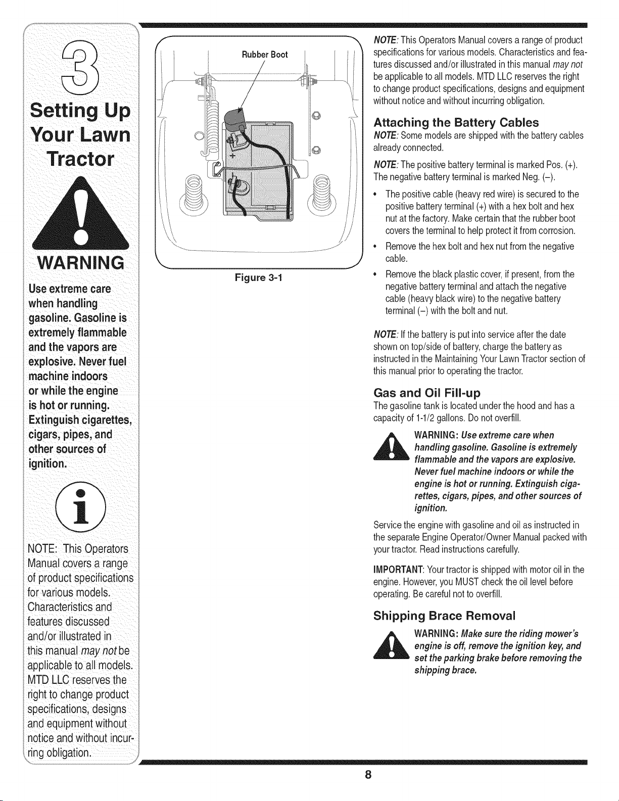
Rubber Boot
Figure 3-1
NOTE:ThisOperatorsManualcoversa rangeof product
specificationsfor variousmodels.Characteristicsandfea-
turesdiscussedand/orillustratedinthis manualmaynot
beapplicableto all models.MTDLLCreservesthe right
to changeproductspecifications,designsandequipment
withoutnoticeandwithoutincurringobligation.
Attaching the Battery Cables
NOTE:Somemodelsare shippedwith the batterycables
alreadyconnected.
NOTE:Thepositivebatteryterminalis markedPos. (+).
Thenegativebatteryterminalis markedNeg.(-).
• Thepositivecable(heavy redwire) is securedto the
positivebatteryterminal(+)with a hexbolt andhex
nut at thefactory.Makecertainthatthe rubberboot
coversthe terminalto helpprotectit fromcorrosion.
• Removethehex boltand hexnut fromthe negative
cable.
Removetheblack plasticcover,ifpresent,fromthe
negativebatteryterminalandattachthe negative
cable(heavyblackwire)to the negativebattery
terminal(-) with thebolt and nut.
NOTE:Ifthe batteryis putinto serviceafter the date
shownontop/sideof battery,chargethe batteryas
instructedin the MaintainingYour LawnTractorsectionof
thismanualpriorto operatingthe tractor.
Gas and Oil Fill-up
Thegasolinetankis locatedunderthe hoodandhasa
capacityof 1-1/2gallons.Donot overfill.
_ WARNING:Useextreme care when
handling gasoline. Gasoline is extremely
flammable and the vapors are explosive.
Neverfuel machine indoors or while the
engine is hot or running. Extinguish ciga-
rettes, cigars, pipes, and other sources of
ignition.
Servicethe enginewithgasolineandoil as instructedin
the separateEngineOperator/OwnerManualpackedwith
yourtractor.Readinstructionscarefully.
IMPORTANT:Yourtractorisshippedwith motoroil inthe
engine.However,you MUSTcheckthe oil levelbefore
operating.Becarefulnotto overfill.
Shipping Brace Removal
WARNING:Makesure the riding mower's
engine is off, removethe ignition key,and
set the parking brake before removing the
shipping brace.
8
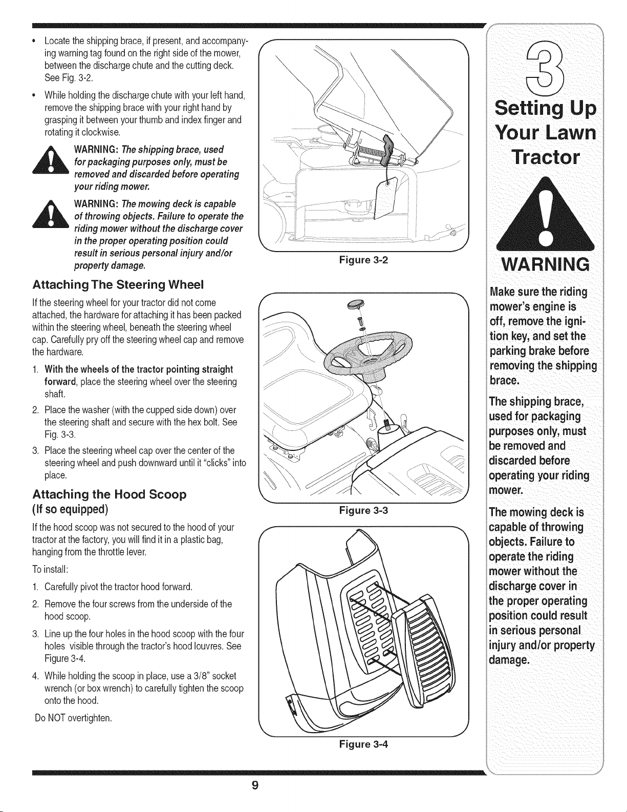
Locatethe shippingbrace,if present,andaccompany-
ing warningtag foundon the rightside of the mower,
betweenthe dischargechuteand thecuttingdeck.
See Fig.3-2.
Whileholdingthe dischargechutewithyourleft hand,
removethe shippingbracewith your righthandby
graspingit betweenyour thumbandindexfingerand
rotatingit clockwise.
WARNING:Theshipping brace, used
for packaging purposes only, must be
removed and discarded before operating
your riding mower.
WARNING:Themowing deck is capable
of throwing objects. Failure to operate the
riding mower without the discharge cover
in the proper operating position could
result in serious personal injury and/or
property damage.
Attaching The Steering Wheel
ifthe steeringwheelforyour tractordid notcome
attached,the hardwarefor attachingit hasbeenpacked
withinthe steeringwheel,beneaththe steeringwheel
cap.Carefullypry offthe steeringwheelcapand remove
the hardware.
1. With the wheels of the tractor pointingstraight
forward, placethe steeringwheeloverthe steering
shaft.
2. Placethe washer(with thecuppedsidedown)over
the steeringshaftandsecurewiththe hex bolt.See
Fig.3-3.
3. Placethe steeringwheelcap overthe centerof the
steeringwheelandpushdownwarduntilit "clicks"into
place.
Attaching the Hood Scoop
(if so equipped)
Ifthe hoodscoopwasnot securedto the hoodof your
tractorat the factory,you willfind it in a plasticbag,
hangingfromthe throttlelever.
To install:
1. Carefullypivot thetractor hoodforward.
2. Removethe fourscrewsfrom the undersideof the
hoodscoop.
.
Lineup thefour holesin the hoodscoopwiththefour
holes visiblethroughthe tractor'shoodIouvres.See
Figure3-4.
4. Whileholdingthe scoopin place,usea 3/8" socket
wrench(or boxwrench)to carefullytightenthe scoop
ontothe hood.
Do NOTovertighten.
Figure 3=2
Figure 3=3
Figure 3-4
YourLawn
Tractor
WARNING
Make sure the riding
mower's engine is
off, remove the igni-
tion key, and set the
parking brake before
removing the shipping
brace.
The shipping brace,
used for packaging
purposes only, must
be removed and
discarded before
operating your riding
mower.
The mowing deck is
capable of throwing
objects. Failure to
operate the riding
mower without the
discharge cover in
the proper operating
position could result
in serious personal
injury and/or property
damage.
9
the seat is engaged in
the seatstop;stand
behindthemachine
and backonseat
until fully engaged
into stopl
i
NOTE: Forshipping rea-
sons seats are either
fastenedtothe tractor
seat's pivot bracket with
a plastiCtie,or mounted
backward tothe pivot
bracketl either case;
freethe seatformits
shipping position and
applicable instructions
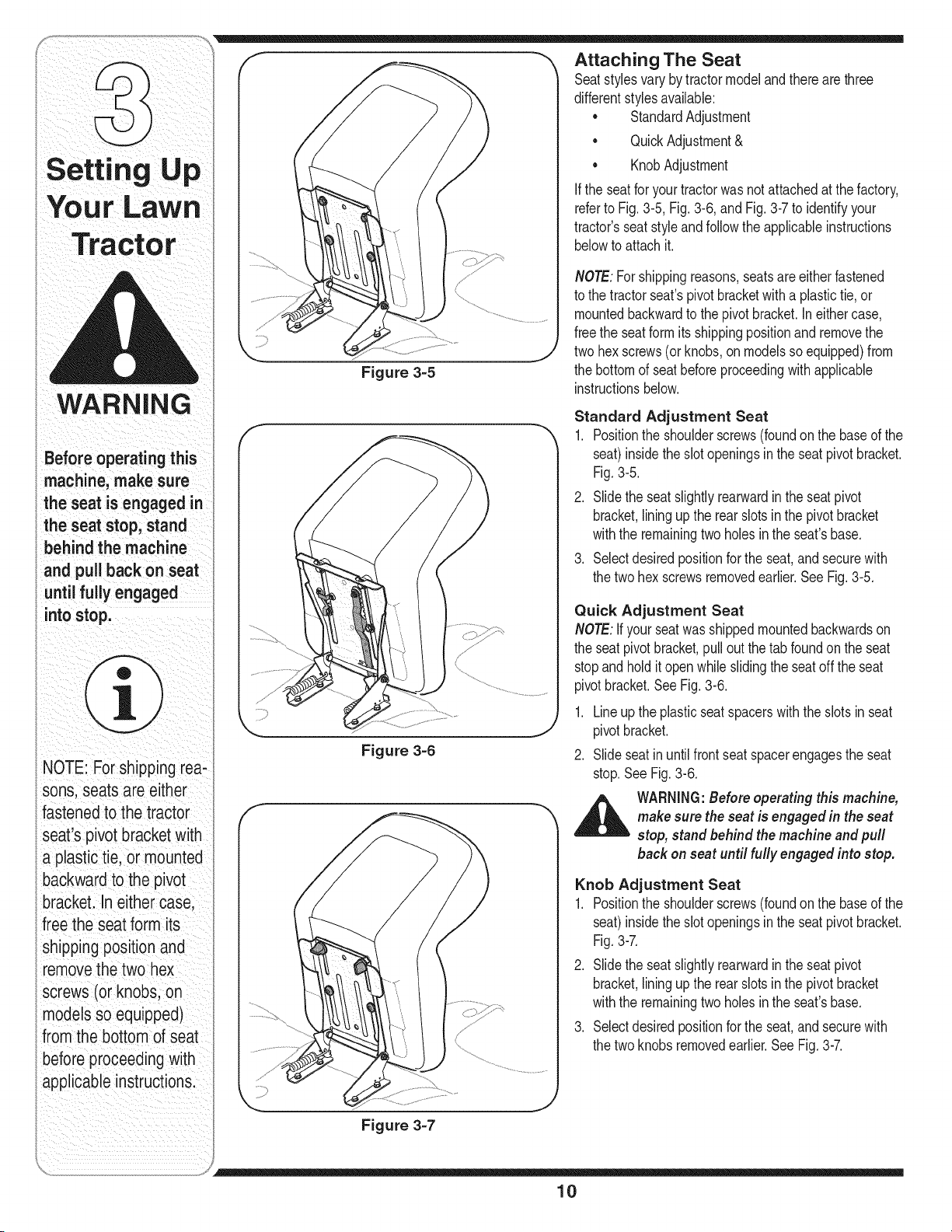
Figure 3-5
Figure 3-6
Figure 3-7
Attaching The Seat
Seatstylesvarybytractormodeland thereare three
differentstylesavailable:
StandardAdjustment
• QuickAdjustment&
• KnobAdjustment
If the seatfor yourtractorwas notattachedat the factory,
referto Fig.3-5, Fig.3-6, andFig.3-7to identifyyour
tractor'sseatstyle andfollowthe applicableinstructions
belowto attachit.
NOTE:Forshippingreasons,seatsareeitherfastened
to the tractorseat'spivotbracketwith a plastictie,or
mountedbackwardto the pivotbracket.Ineithercase,
freethe seatformitsshippingpositionand removethe
twohex screws(or knobs,on modelsso equipped)from
the bottomd seatbeforeproceedingwithapplicable
instructionsbelow.
Standard Adjustment Seat
1. Positionthe shoulderscrews(foundonthe based the
seat)insidetheslotopeningsinthe seatpivotbracket.
Fig.3-5.
2. Slidethe seatslightlyrearwardinthe seatpivot
bracket,liningupthe rearslots inthe pivotbracket
withthe remainingtwo holesin the seat'sbase.
3. Selectdesiredpositionforthe seat,andsecurewith
the twohex screwsremovedearlier.SeeFig.3-5.
Quick Adjustment Seat
NOTE:ifyour seatwas shippedmountedbackwardson
the seatpivotbracket,pulloutthe tab foundonthe seat
stopandholditopenwhileslidingthe seatoff the seat
pivotbracket.SeeFig.3-6.
1. Lineupthe plasticseatspacerswith the slotsin seat
pivotbracket.
2. Slideseatinuntilfrontseatspacerengagesthe seat
stop.SeeFig.3-6.
bi_ make surestop,WARNINGstandbehindthe machine and pull:theseat is engaged in theBef°re operating thismachine,seat
back on seat until fully engaged into stop.
Knob Adjustment Seat
1. Positionthe shoulderscrews(foundonthe based the
seat)insidetheslotopeningsinthe seatpivotbracket.
Fig.3-7.
2. Slidethe seatslightlyrearwardinthe seatpivot
bracket,liningupthe rearslots inthe pivotbracket
withthe remainingtwo holesin the seat'sbase.
3. Selectdesiredpositionforthe seat,andsecurewith
the twoknobsremovedearlier.SeeFig.3-7.
10
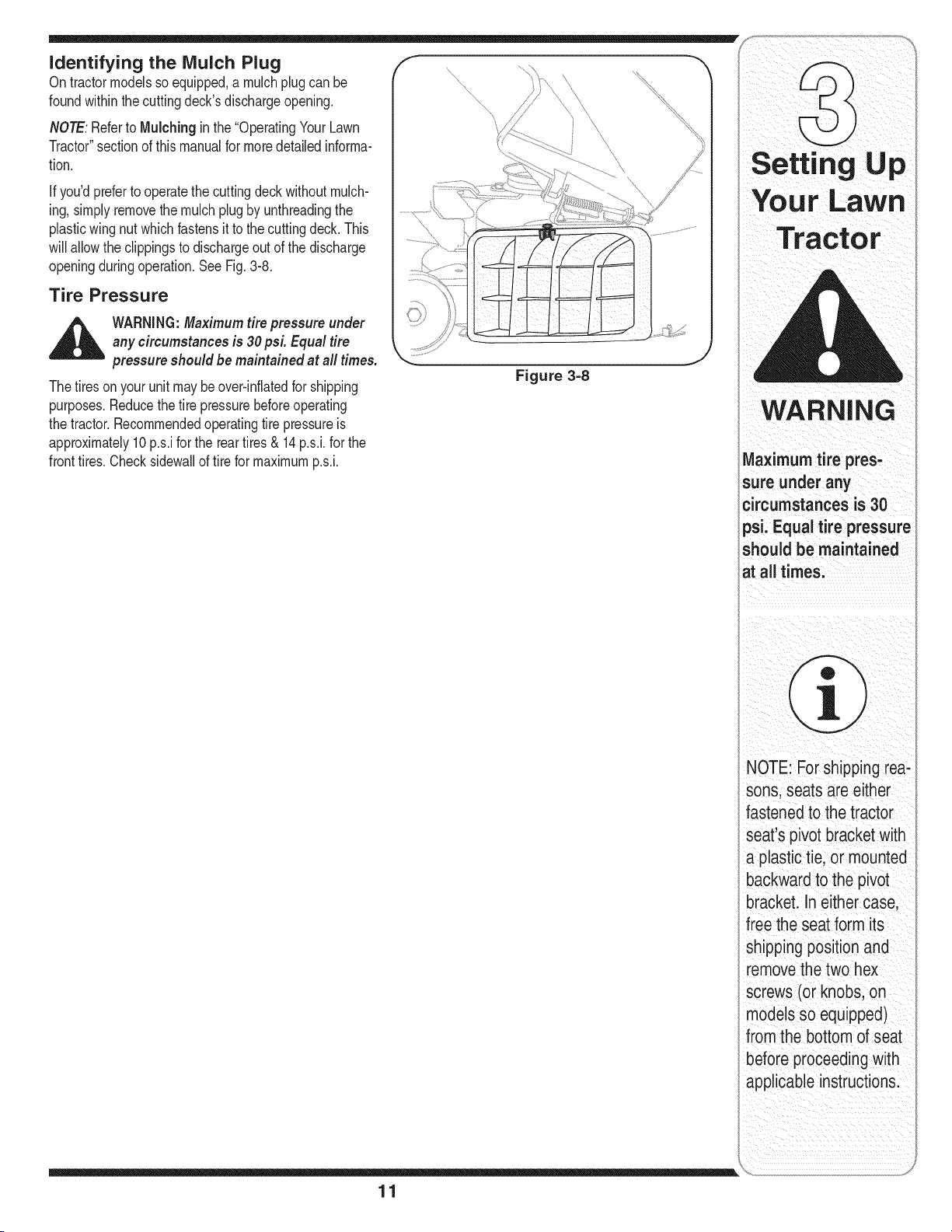
identifying the lVluich Plug
On tractormodelssoequipped,a mulchplugcan be
foundwithinthecuttingdeck'sdischargeopening.
NOTE:Referto Mulching in the"OperatingYourLawn
Tractor"sectionof thismanualfor moredetailedinforma-
tion.
Ifyou'dpreferto operatethe cuttingdeck withoutmulch-
ing, simplyremovethe mulchplugby unthreadingthe
plasticwing nutwhichfastensit to the cuttingdeck.This
will allowthe clippingsto dischargeout of the discharge
openingduringoperation.SeeFig.3-8.
Tire Pressure
,_ WARNING:Maximum tire pressure under
any circumstances is 30psL Equal tire
pressure should be maintained at all times.
The tiresonyour unitmaybeover-inflatedfor shipping
purposes.Reducethetire pressurebeforeoperating
the tractor.Recommendedoperatingtire pressureis
approximately10p.s.ifor the reartires& 14p.s.i,for the
fronttires.Checksidewallof tirefor maximump.s.i.
....,\\\\\
Figure 3=8
Setting Up
WARNING
Maximum tire pres'
sure under any
circumstances is 30
psi, Equal tire pressure
should be maintained
at all times,
11
NOTE: For shipping red:
sons, seats are either
fastened tothe tractor
Seats pivot_ bracket With
a plastic tie, or mounted
backwardto the pivot
brackeL In eithercase
free the seat form its
shipping position and
removethe two hex
screws(or knobs; on
models so equipped)
from the bottom of seat
before proceedingwith
p# le instructions:
NOTE:Anyreference
inthismanualto the
RIGHTorLEFTsideof
thetractorisobserved
fromoperator'sposition.
NOTE:Forshippingrea-
sons,seatsareeither
fastenedtothetractor
seat'spivotbracketwith
aplastictie,ormounted
backwardtothepivot
bracket.Ineithercase
freetheseatformits
shippingpositionand
removethetwohex
screws(orknobs,on
modelssoequipped)
fromthebottomofseat
beforeproceedingwith
applicableinstructions.
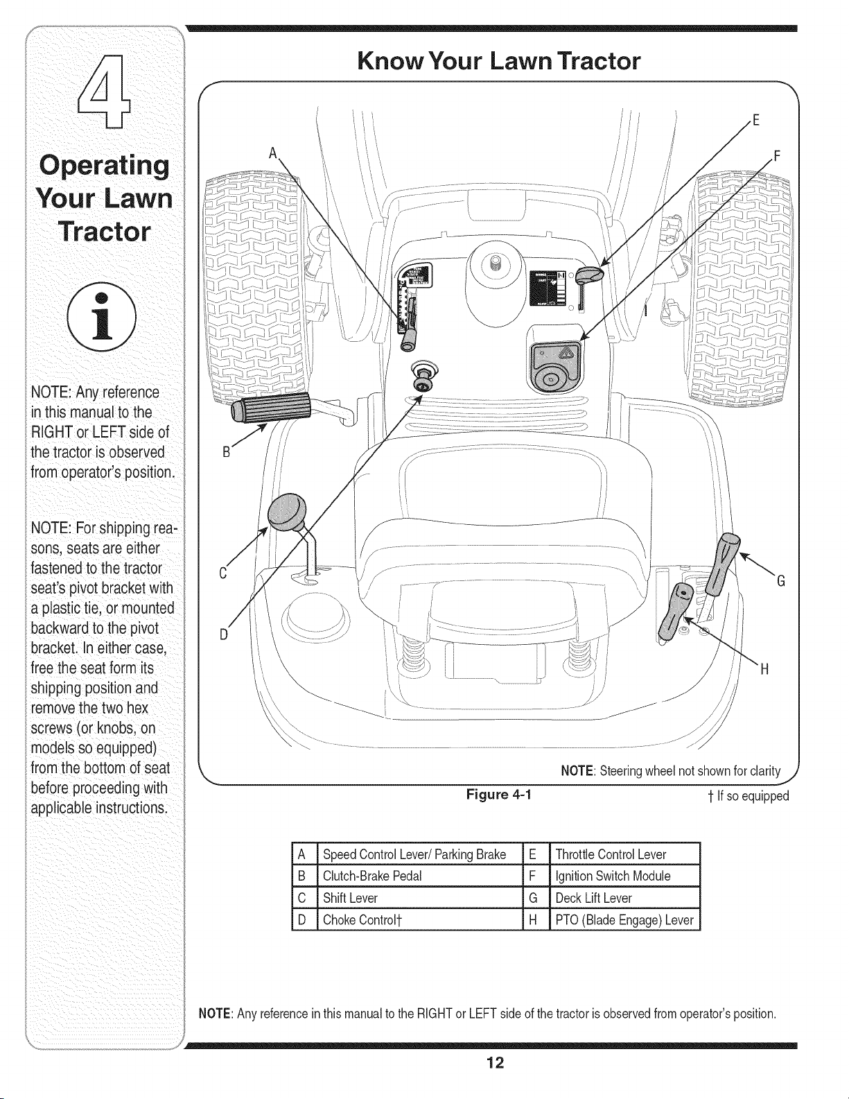
Know Your Lawn Tractor
A
\
Figure 4=1
NOTE:Steeringwheelnot shownfor clarity
1-If soequipped
A SpeedControlLever/ParkingBrake E ThrottleControlLever
B Clutch-BrakePedal F IgnitionSwitchModule
C ShiftLever G DeckLift Lever
D ChokeControl1- H PTO(BladeEngage)Lever
NOTE:Anyreferencein this manualto the RIGHTor LEFTside of the tractoris observedfrom operator'sposition.
12
m
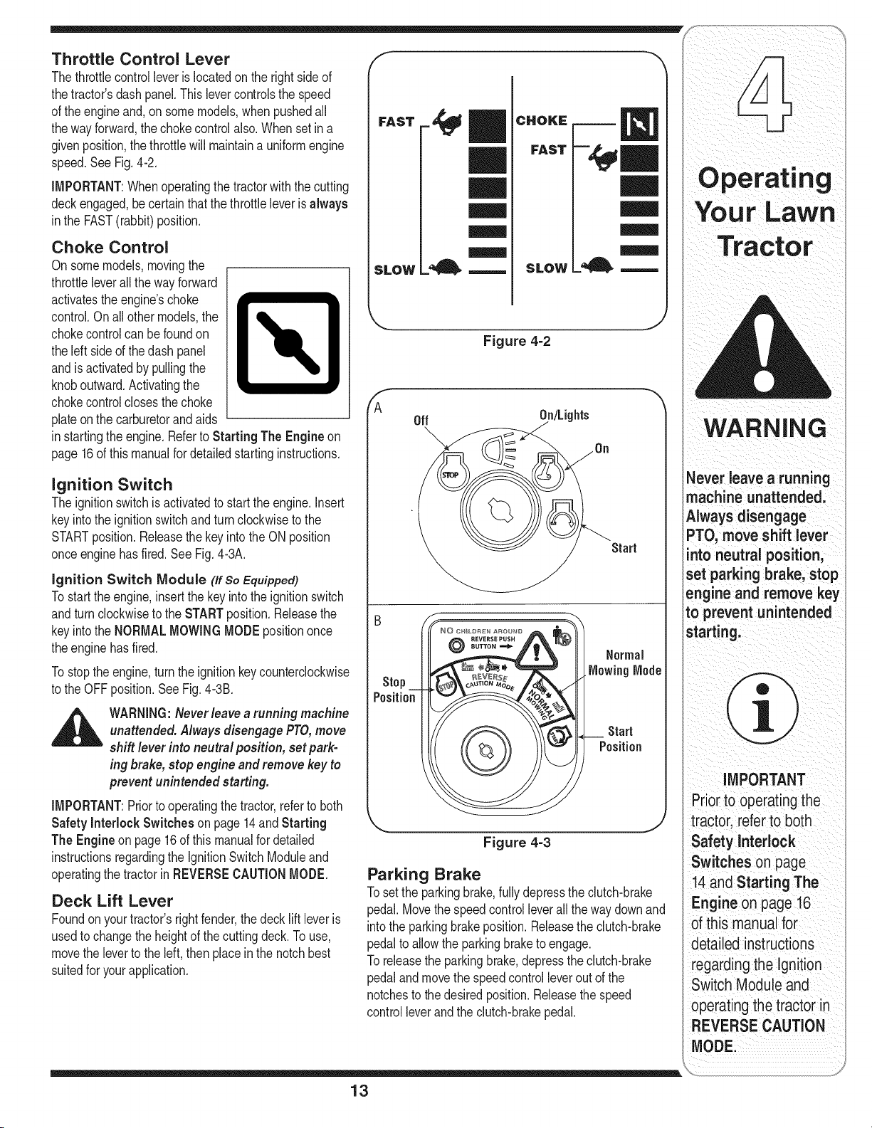
Throttle Control Lever
Thethrottlecontrolleveris locatedon the rightside of
thetractor'sdash panel.Thislevercontrolsthe speed
of the engineand,on somemodels,when pushedall
thewayforward,the chokecontrolalso.Whenset ina
givenposition,the throttlewill maintaina uniformengine
speed.SeeFig.4-2.
iMPORTANT:Whenoperatingthetractorwith the cutting
deckengaged,becertainthatthe throttleleverisalways
inthe FAST(rabbit)position.
Choke Control
Onsomemodels,movingthe
throttleleverallthe wayforward
activatestheengine'schoke
control.Onall othermodels,the
chokecontrolcan befoundon
the leftside of thedash panel
andisactivatedby pullingthe
knoboutward.Activatingthe
chokecontrolclosesthe choke
plateonthe carburetorandaids
instartingthe engine.Referto Starting The Engine on
page16of thismanualfor detailedstartinginstructions.
Ignition Switch
The ignitionswitchisactivatedto startthe engine,insert
keyintothe ignitionswitchand turnclockwiseto the
STARTposition.Releasethe key intothe ON position
onceenginehasfired.SeeFig.4-3A.
ignition Switch Module (If So Equipped)
Tostart theengine,insertthe keyintothe ignitionswitch
andturnclockwiseto the STARTposition.Releasethe
keyintothe NORMALMOWINGMODEpositiononce
theenginehasfired.
Tostopthe engine,turn theignitionkeycounterclockwise
to the OFFposition.SeeFig.4-3B.
WARNING:Neverleave arunning machine
unattended. Always disengage PTO,move
shift lever into neutral position, set park-
ing brake, stop engine and remove key to
prevent unintended starting.
iMPORTANT:Priorto operatingthetractor,referto both
Safety interlock Switches on page14and Starting
The Engine on page 16 of this manualfordetailed
instructionsregardingthe ignitionSwitchModuleand
operatingthe tractorinREVERSECAUTIONMODE.
Deck Lift Lever
Foundon yourtractor'srightfender,the decklift leveris
usedto changetheheightof the cuttingdeck.To use,
movethe leverto the left,then placeinthe notchbest
suitedfor yourapplication.
F
FAST
SLOW
|l
CHOKE
FAST
SLOW
Figure 4=2
_A
Off On/Lights
Start
Stop
Position
©
Start
Position
Figure 4-3
Parking Brake
To setthe parkingbrake,fullydepressthe dutch-brake
pedal.Movethe speedcontrolleverall theway downand
intothe parkingbrakeposition.Releasethe clutch-brake
pedalto allowthe parkingbraketo engage.
To releasethe parkingbrake,depresstheclutch-brake
pedalandmovethe speedcontrolleveroutof the
notchesto thedesiredposition.Releasethespeed
controlleverandthe clutch-brakepedal.
_ever leave a running
machine unattended,
Always disengage
PTO, move shift lever
nto neutral position,
set parking brake, stop
engine and remove key
to prevent unintended
starting:
MPORTANT
Prior_o0
tractori refe!to both
Safety Interlock ;
Switches onpage
14. and starting The
:Engineonpage16
detailedinstraCtions
regardingtheIgnition
Switch Moduleand
operating the tractor in
REVERSE CAUTION
ODEi
13
WARNING
Dooctop rato
tractor ifthe interlock
ing: This system was
safetyaodproteot oo,
NOTE: The parking
brakemustbesetifthe
operator leavesthe seat
with theengine
ning or the enginewi
automatiCallyshut ofL
NOTE: The PTO (Blade
Engage) lever must be
inthe disengaged (PTO
OFF) position when
starting the engine:
IMPORTANT
Never force the shift
lever:Do ngso may
result in serious
damage to the tractorls
transmissionl
FRRWARD
NUETRAL
REVERSE_
Figure 4-4
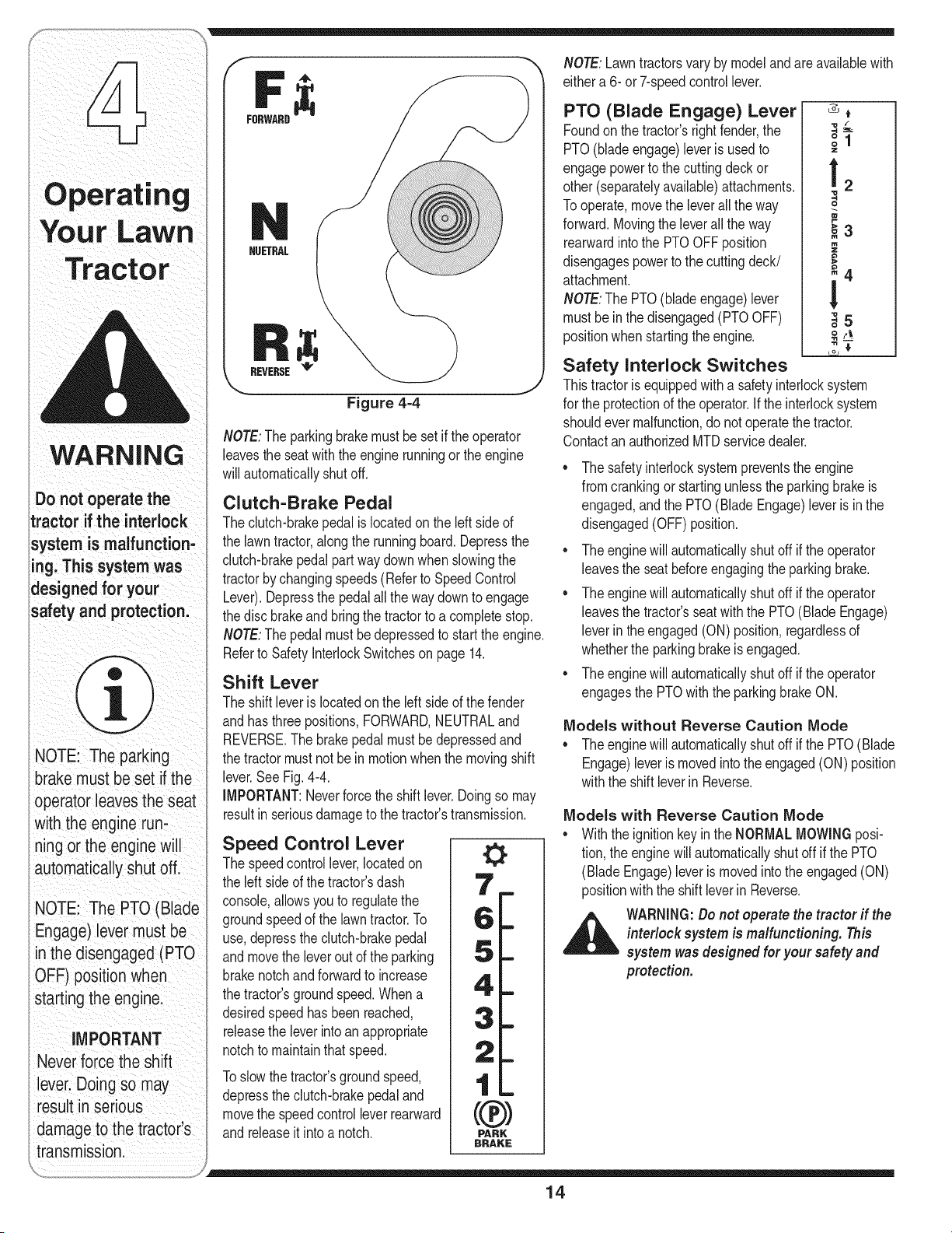
NOTE:Theparkingbrakemustbe set if theoperator
leavesthe seatwiththe enginerunningor the engine
willautomaticallyshutoff.
Clutch-Brake Pedal
Theclutch-brakepedalis locatedonthe left sideof
the lawntractor,alongthe runningboard.Depressthe
clutch-brakepedalpartwaydownwhenslowingthe
tractorbychangingspeeds(Referto SpeedControl
Lever).Depressthe pedalall theway downto engage
thedisc brakeand bringthe tractorto a completestop.
NOTE:Thepedal mustbe depressedto startthe engine.
Referto SafetyInterlockSwitcheson page 14.
Shift Lever
The shiftleverislocatedon the left sideof thefender
andhasthree positions,FORWARD,NEUTRALand
REVERSE.The brakepedalmustbedepressedand
thetractor mustnotbe in motionwhenthe movingshift
lever.SeeFig.4-4.
IMPORTANT:Neverforcethe shiftlever.Doingso may
resultinseriousdamageto the tractor'stransmission.
Speed Control Lever
The speedcontrollever,locatedon
the leftside of thetractor'sdash
console,allowsyouto regulatethe
groundspeedof the lawntractor.To
use,depressthe clutch-brakepedal
andmovethe leveroutof the parking
brakenotchandforwardto increase
thetractor'sgroundspeed.Whena
desiredspeedhas beenreached,
releasethe leverintoan appropriate
notchto maintainthatspeed.
Toslowthetractor'sgroundspeed,
depressthe clutch-brakepedaland
movethe speedcontrolleverrearward
andreleaseit intoa notch.
0
0
PARK
BRAKE
NOTE:Lawntractorsvary by modeland are availablewith
eithera 6- or7-speedcontrollever.
PTO (Blade Engage) Lever
Foundon the tractor'srightfender,the
PTO(bladeengage)leveris usedto
engagepowerto the cuttingdeckor
other(separatelyavailable)attachments.
Tooperate,movethe leverall the way
forward.Movingthe leverall the way
rearwardintothe PTOOFF position
disengagespowerto the cuttingdeck/
attachment.
NOTE:The PTO(blade engage)lever
mustbe in the disengaged(PTOOFF)
positionwhenstartingthe engine.
"O /"
!2
o
_3
m
_4
!
"o
,t5
Safety Interlock Switches
Thistractorisequippedwitha safetyinterlocksystem
for the protectionof the operator,if the interlocksystem
shouldever malfunction,donot operatethe tractor.
ContactanauthorizedMTDservicedealer.
Thesafetyinterlocksystempreventstheengine
fromcrankingor startingunlessthe parkingbrakeis
engaged,andthe PTO(BladeEngage)leveris inthe
disengaged(OFF)position.
* Theenginewill automaticallyshutoff if the operator
leavesthe seatbeforeengagingthe parkingbrake.
* Theenginewill automaticallyshutoff if the operator
leavesthe tractor'sseatwith the PTO(Blade Engage)
leverinthe engaged(ON) position,regardlessof
whetherthe parkingbrakeis engaged.
* Theenginewill automaticallyshutoff if the operator
engagesthe PTOwith the parkingbrakeON.
Models without Reverse Caution Mode
,, Theenginewill automaticallyshut off if the PTO(Blade
Engage)leveris movedinto the engaged(ON) position
withthe shift leverin Reverse.
Models with Reverse Caution Mode
* Withthe ignitionkeyinthe NORMALMOWINGposi-
tion,the enginewillautomaticallyshutoff if the PTO
(BladeEngage)leveris movedintothe engaged(ON)
positionwiththe shift leverinReverse.
_ ARNING: Do not operate the tractor if the
interlock system is malfunctioning. This
system wasdesigned for your safety and
protection.
14
Reverse Caution Mode
(Models equipped with ignition switch
module)
_il= ARNING:Useextreme caution while
operating the tractor in the REVERSE
CAUTIONMODE.Always look down and
behind before and while backing. Do
notoperate the tractor when children
or others arearound. Stop the tractor
immediately if someone enters the area.
The REVERSECAUTIONMODEpositionof the key
switchmoduleallowsthetractorto be operatedin
reversewiththe blades(PTO)engaged.
IMPORTANT:Mowingin reverseis notrecommended,
Tousethe REVERSECAUTIONMODE:
IMPORTANT:The operatorMUSTbe seatedinthe
tractorseat.
1, Startthe engineas instructedon page 16under
Starting The Engine.
2. Turnthe keyfromthe NORMALMOWING(Green)
positionto the REVERSECAUTIONMODE(Yellow)
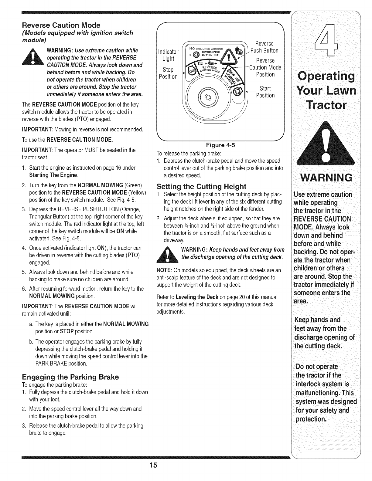
positionof the keyswitchmodule. See Fig. 4-5.
3. Depressthe REVERSEPUSHBUTTON(Orange,
TriangularButton)at the top,rightcornerof the key
switchmodule.The redindicatorlightat thetop,left
cornerof the keyswitchmodulewill be ONwhile
activated.SeeFig.4-5.
4. Onceactivated(indicatorlight ON),thetractorcan
bedriveninreversewiththe cuttingblades(PTO)
engaged.
5. Alwayslookdownand behindbeforeandwhile
backingto makesureno childrenare around.
6. Afterresumingforwardmotion,returnthe keyto the
NORMALMOWINGposition.
IMPORTANT:The REVERSECAUTIONMODEwill
remainactivateduntil:
a. Thekeyis placedin eitherthe NORMALMOWING
positionor STOPposition.
b. Theoperatorengagesthe parkingbrakebyfully
depressingtheclutch-brakepedalandholdingit
downwhilemovingthe speedcontrol leverintothe
PARKBRAKEposition.
Indicator
Light
Stop
Position
©
Reverse
. PushButton
Reverse
CautionMode
Position
Start
Position
Figure 4-5
To releasethe parkingbrake:
1. Depressthe clutch-brakepedalandmovethe speed
controlleverout of the parkingbrakepositionand into
a desiredspeed.
Setting the Cutting Height
1. Selectthe heightpositionof the cuttingdeckby plac-
ingthe decklift leverinany of the six differentcutting
heightnotcheson the rightsideof thefender.
2. Adjustthe deckwheels,ifequipped,sothat theyare
between1A-inchand V2-inchabovethe groundwhen
the tractoris ona smooth,flat surfacesuch as a
driveway.
d_ltlb WARNING: Keep hands and feet away from
the discharge opening of the cutting deck.
NOTE:On modelssoequipped,the deckwheelsarean
anti-scalpfeatureof the deckandarenotdesignedto
supportthe weightof the cuttingdeck.
Referto Levelingthe Deckon page20 of thismanual
for moredetailedinstructionsregardingvariousdeck
adjustments.
Engaging the Parking Brake
Toengagethe parkingbrake:
1. Fullydepressthe clutch-brakepedalandhold it down
withyourfoot.
2. Movethe speedcontrolleverallthe waydownand
intothe parkingbrakeposition.
3. Releasethe clutch-brakepedalto allowthe parking
braketo engage.
15
I
Use extreme caution
while operating
the tractor in the
REVERSE CAUTION
MODE. Always look
down and behind
before and while
backing. Do not oper-
ate the tractor when
children or others
are around. Stop the
tractor immediately if
someone enters the
area.
Keep hands and
feet away from the
discharge opening of
the cutting deck.
Do not operate
the tractor if the
interlock system is
malfunctioning. This
system was designed
for your safety and
protection.
WARNING
if you strike a foreign
object, stop the engine,
disconnect the spark
plugwire(s) and
ground against the
engine.Thoroughly
inspectthe machine for
any damage. Repair the
damage before restart-
ingand operating.
Avoid sudden starts,
ex-cessive speed and
sudden stops.
Do not leavethe seat
of the tractor without
first placingthe PTO
(Blade Engage)lever in
the disengaged (OFF)
position, depressing
the brake pedal and
engagingthe parking
brake. If leaving the
tractor unattended, also
turn the ignitionkey off
and remove the key.
Always look down
and behind before
and while backing up
to avoid a back-over
Starting the Engine
_ ARNING:Do not operate the tractor if
the interlock system is malfunctioning.
Thissystem wasdesigned for your safety
andprotection.
NOTE:Referto the TRACTORSET=UPon page8 of
thismanualfor Gasolineand Oil fill-upinstructions.
1. Insertthe tractorkeyintothe ignitionswitch.
2. Placethe PTO(BladeEngage)leverinthe disen-
gaged(OFF)position.
3. Engagethetractor'sparkingbrake.
4. Activatethe chokecontrol.
5. Turnthe ignitionkeyclockwiseto the STARTposi-
tion.Afterthe enginestarts,releasethe key.It will
returnto the ON(or NormalMowing)position.
IMPORTANT:DoNOTholdthe keyin the START
positionfor longerthanten secondsat a time. Doingso
maycausedamageto yourengine'selectricstarter.
6. Afterthe enginestarts,deactivatethe chokecontrol
andplacethe throttlecontrolin the FASTposition.
NOTE:Do NOTleavethe chokecontrolonwhile operat-
ingthe tractor.Doingsowill resultina "rich" fuelmixture
andcausethe engineto runpoorly.
Stopping the Engine
_ ARNING: If you strike a foreign object,
stop the engine, disconnect the spark
plug wire(s) and ground against the
engine. Thoroughly inspect the machine
for any damage. Repair the damage
before restarting and operating
1. If the bladesare engaged,placethe PTO(Blade
Engage)leverin the disengaged(OFF)position.
2. Turnthe ignitionkeycounterclockwiseto the STOP
position.
3. Removethe keyfromthe ignitionswitchto prevent
unintendedstarting.
Driving The Tractor
_ WARNING:Avoid sudden starts, ex-ces-
sive speed and sudden stops.
WARNING:Do not leave the seat of the
tractor without first placing the PTO
(Blade Engage) lever in the disengaged
(OFF)position, depressing the brake
pedal and engaging the parking brake. If
leaving the tractor unattended, also turn
the ignition key off and remove the key.
Always look down and behind before and
while backing up to avoid a back-over
accident.
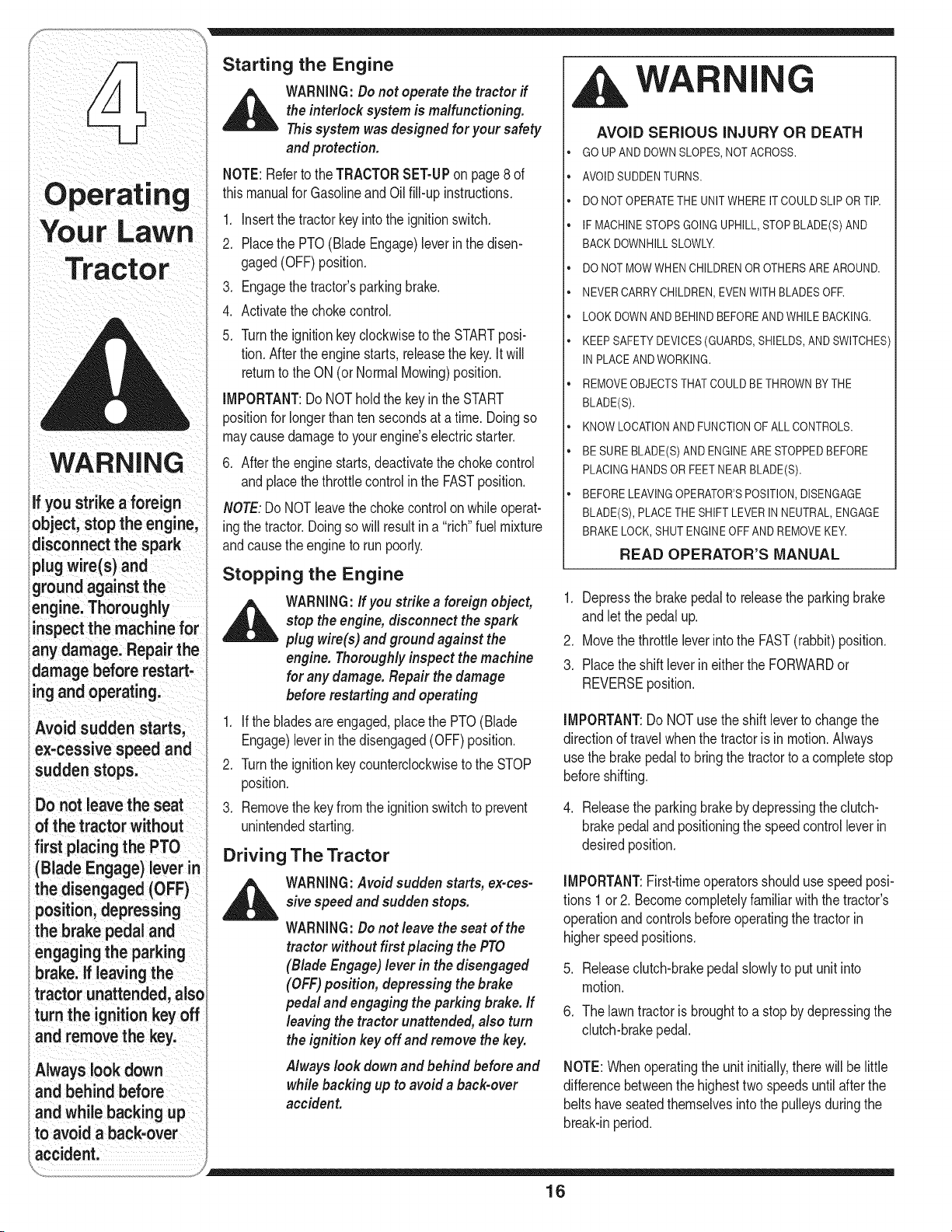
WA I
AVOID SERIOUS INJURY OR DEATH
GO UPAND DOWNSLOPES,NOT ACROSS.
AVOIDSUDDENTURNS.
DO NOT OPERATETHEUNITWHERE IT COULDSLIP OR TIR
IF MACHINESTOPSGOINGUPHILL,STOP BLADE(S)AND
BACK DOWNHILLSLOWLY.
DO NOT MOWWHEN CHILDRENOROTHERS AREAROUND.
NEVER CARRYCHILDREN,EVENWITH BLADESOFR
LOOK DOWNAND BEHIND BEFOREAND WHILE BACKING.
KEEP SAFETYDEVICES(GUARDS,SHIELDS,AND SWITCHES)
IN PLACEAND WORKING.
REMOVEOBJECTSTHATCOULDBE THROWNBYTHE
BLADE(S).
KNOW LOCATIONAND FUNCTIONOF ALL CONTROLS.
BE SURE BLADE(S)AND ENGINEARE STOPPEDBEFORE
PLACING HANDSOR FEETNEAR BLADE(S).
BEFORE LEAVINGOPERATOR'SPOSITION,DISENGAGE
BLADE(S), PLACETHE SHIFTLEVERIN NEUTRAL,ENGAGE
BRAKE LOCK,SHUT ENGINEOFF AND REMOVEKEY.
READ OPERATOR'S MANUAL
1. Depressthe brakepedalto releasethe parkingbrake
andlet the pedalup.
2. Movethe throttleleverintothe FAST(rabbit)position.
3. Placethe shift leverineitherthe FORWARDor
REVERSEposition.
IMPORTANT:Do NOTusethe shift leverto changethe
directionof travelwhenthe tractoris in motion.Always
use the brakepedalto bringthetractorto a completestop
beforeshifting.
4. Releasethe parkingbrakebydepressingthe clutch-
brakepedaland positioningthe speedcontrol leverin
desiredposition.
IMPORTANT:First-timeoperatorsshoulduse speedposi-
tions 1 or 2. Becomecompletelyfamiliarwith the tractor's
operationandcontrolsbeforeoperatingthetractorin
higherspeedpositions.
.
6.
Releaseclutch-brakepedalslowlyto put unitinto
motion.
The lawntractoris broughtto a stopby depressingthe
clutch-brakepedal.
NOTE:Whenoperatingthe unitinitially,therewill be little
differencebetweenthe highesttwo speedsuntilafter the
beltshaveseatedthemselvesintothe pulleysduringthe
break-inperiod.
16
WARNING:Before leavingthe operator's
positionfor any reason,disengage the
blades,place the shift lever in neutral,
engagethe parking brake, shut engine off
and remove the key.
iMPORTANT:Whenstoppingthe tractorfor any reason
whileona grass surface,always:
1. Placethe shiftleverin neutral,
2. Engagethe parkingbrake,
3. Shutengineoff and removethe key.
Doingso will minimizethe possibilityof havingyourlawn
"browned" byhot exhaustfrom yourtractor'srunning
engine.
If unit stalls with speedcontrolin high speed,or if unit
will notoperatewith speedcontrolleverina low speed
position,proceedas follows:
1. Placeshift leverin NEUTRAL.
2. Restartengine.
3. Placespeedcontrolleverinhighestspeedposition.
4. Releaseclutch-brakepedalfully.
5. Depressclutch-brakepedal.
6. Placespeedcontrolleverindesiredposition.
7. Placeshift leverin eitherFORWARDor REVERSE,
andfollownormaloperatingprocedures.
Engaging the Blades
Engagingthe PTO(BladeEngage)transferspowerto the
cuttingdeckor other(separatelyavailable)attachments.
Toengagetheblades,proceedas follows:
1. Movethe throttlecontrolleverto the FAST(rabbit)
position.
2. Graspthe PTO(Blade Engage)leverand pivot it all
thewayforwardintothe engaged(ON)position.
3. Keepthe throttleleverinthe FAST(rabbit)position
forthe mostefficientuseof the cuttingdeck or other
(separatelyavailable)attachments.
iMPORTANT:ModelswithReverseCaution Mode:
Theenginewill automaticallyshutoff if the PTOis
engagedwiththe shift leverinpositionfor reversetravel
withtheignitionkey in the NORMALMOWINGposition.
Modelswithout ReverseCaution Mode:
The PTO(BladeEngage)levermustbe inthe disen-
gaged(OFF)positionwhenstartingthe engine,when
travelingin reverse,and if theoperatorleavesthe seat.
Referto SafetyInterlockSwitchesonpage14.
Using the Deck Lift Lever
Toraisethe cuttingdeck,movethe deck lift leverto
theleft, then placeitinthe notchbestsuitedfor your
application.Referto SettingThe CuttingHeightearlierin
thissection.
Driving On Slopes
Referto the SLOPEGAUGEon page3 to helpdetermine
slopeswhereyoumayoperatethe tractorsafely.
o
o
WARNING:Do not mow on inclines with
aslope in excessof 15degrees (a rise of
approximately 2-1/2 feet every 10feet). The
tractor could overturn and cause serious
injury.
Mowupanddownslopes,NEVERacross,
Exerciseextremecautionwhenchangingdirectionon
slopes,
Watchfor holes,ruts,bumps,rocks,or otherhidden
objects.Uneventerraincouldoverturnthe machine,
Tallgrasscan hideobstacles.
Avoidturnswhendrivingon a slope.If a turn mustbe
made,turndownthe slope.Turningup a slopegreatly
increasesthe chanceof a roll over,
Avoidstoppingwhendrivingupa slope, if it is
necessaryto stopwhiledrivingupa slope, startup
smoothlyandcarefullyto reducethe possibilityof
flippingthe tractoroverbackward.
WARNING
Do not mow on
inclineswith a slope
in excess of 15
degrees (a rise of
approximately 2-1/2
feet every 10 feet).
The tractor could
overturn and cause
serious injury.
17
Your Lawn
Tracto
WARNING
To help avoid blade
contact or a thrown
object injury, keep
bystanders, helpers,
children and pets at
least 75 feet from the
machine while it is in
operation. Stop ma=
chine if anyone enters
the area.
Planyour mowing
pattern to avoid
discharge of mated-
DiStoward roads,
sidewalks, bystanders
and the like. Also,
avoid discharging
material against a wall
or obstruction which
may cause discharged
material to ricochet
back toward the
operator.
Mowing
_ ARNING:Tohelp avoid blade contact or
a thrown objectinjury, keep bystanders,
helpers, children and pets at least 75feet
from the machine while it is in operation.
Stop machine if anyone enters the area.
Thefollowinginformationwill behelpfulwhenusingthe
cuttingdeckwithyourtractor:
_ WARNING:Plan your mowing pattern
to avoid discharge of materials toward
roads, sidewalks, bystanders and the like.
Also, avoid discharging material against
a wall or obstruction which may cause
discharged material to ricochet back
toward the operator.
• Do notmow at high groundspeed,especiallyif a
mulchkitorgrasscollectoris installed.
• Forbest resultsit is recommendedthatthe firsttwo
laps becutwiththe dischargethrowntowardsthe
center.Afterthefirst two laps, reversethe direction
to throwthe dischargeto the outsidefor the balance
of cutting.Thiswill givea betterappearanceto the
lawn.
Do notcut thegrass too short.Shortgrassinvites
weedgrowthandyellowsquicklyin dry weather.
• Mowingshouldalwaysbe donewith the engine at full
throttle.
• Underheavierconditionsit maybe necessaryto go
backoverthe cut areaa secondtimeto get a clean
cut.
• Do NOTattemptto mow heavybrushand weedsand
extremelytall grass.Yourtractoris designedto mow
lawns,NOTclearbrush.
• Keepthe bladessharpand replacethe bladeswhen
worn.Referto Cutting Blades onpage25 of this
manualfor properbladesharpeninginstructions.
WA
G
AVOID SERIOUS INJURY OR DEATH
• GO UP AND DOWNSLOPES,NOT ACROSS.
• AVOID SUDDENTURNS.
• DO NOT OPERATETHEUNITWHERE IT COULDSLIP
OR TIR
• IF MACHINESTOPSGOINGUPHILL,STOP BLADE(S)
AND BACK DOWNHILLSLOWLY.
,, DO NOT MOWWHEN CHILDRENOR OTHERSARE
AROUND.
• NEVER CARRYCHILDREN,EVENWITH BLADESOFR
• LOOK DOWNAND BEHINDBEFOREAND WHILE
BACKING.
• KEEP SAFETYDEVICES(GUARDS,SHIELDS,AND
SWITCHES)IN PLACE ANDWORKING.
• REMOVEOBJECTSTHATCOULD BE THROWNBY
THE BLADE(S).
• KNOW LOCATIONANDFUNCTIONOF ALL CON
TROLS.
• BE SUREBLADE(S) AND ENGINEARE STOPPED
BEFORE PLACINGHANDSOR FEETNEAR
BLADE(S).
• BEFORE LEAVINGOPERATOR'SPOSITION,DISEN
GAGEBLADE(S), PLACETHE SHIFTLEVERIN
NEUTRAL, ENGAGEBRAKELOCK, SHUT ENGINE
OFF AND REMOVE KEY.
READ OPERATOR'S MANUAL
18
Mulching
Selectmodelscomeequippedwitha mulch kit which
incorporatesspecialblades,alreadystandardonthe
tractor,ina processof recirculatinggrass clippings
repeatedlybeneaththe cuttingdeck.Theultra-fine
clippingsarethen forcedbackintothe lawnwherethey
actas a naturalfertilizer.
Observethe followingpointsfor the bestresultswhen
mulching:
• Neverattemptto mulchif the lawnisdamp.Wet grass
tendsto stickto theundersideof the cuttingdeck
preventingpropermulchingof the clippings.
Do NOTattemptto mulchmorethan 1/3the total
heightof the grassor approximately1-1/2inches.
Doingso willcausetheclippingsto clump up beneath
thedeckand notbe mulchedeffectively.
• Maintaina slow groundspeedto allowthe grass
clippingsmoretimeto effectivelybemulched.
• Alwayspositionthe throttlecontrol leverinthe FAST
(rabbit)positionandallowit to remaintherewhile
mowing.Failingto keepthe engineat full throttle
placesstrainon the tractor'sengineand doesnot
allowthe bladesto properlymulchgrass.
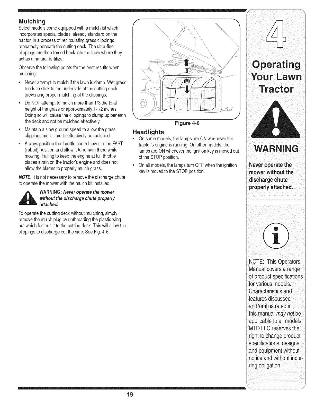
NOTE:It isnot necessaryto removethe dischargechute
to operatethe mowerwiththe mulchkit installed.
_ WARNING:Never operate the mower
without the discharge chute properly
attached.
Tooperatethe cuttingdeck withoutmulching,simply
removethe mulchplugbyunthreadingthe plasticwing
nutwhichfastensit to the cuttingdeck.Thiswill allowthe
clippingsto dischargeout the side.See Fig.4-6.
Figure 4-6
Headlights
• On somemodels,the lampsare ONwheneverthe
tractor'sengineis running.On othermodels,the
lampsareONwheneverthe ignitionkeyis movedout
of the STOPposition.
• Onall models,the lampsturn OFF whenthe ignition
keyis movedto the STOPposition.
19
i_ ii i i
mower without the
dischargech
propedy attached,
T ¸¸¸
NOTE: This 0
ManUa covers a range
of product specifications
for VariOusmodels:
characteristics and
features discussec
andlor Ilustratedin
his manual may not be
_tpplicableto all modelsl
MTD LLCreserves the
rightto changeproduct
specifications designs
and equipmentWithout
not ce and WithoutincUr_
ring obligation.
i
WARNING
Neverattemptto
make any adjust-
ments while the
engine is running,
except where speci-
i fied in the operator's
manual.
f
Figure 5=1
Figure 5=2
,_ WARNING:Neverattempt to make any
adjustments while the engine is running,
except where specified in the operator's
manual.
1. Withthe tractorparkedon a firm,levelsurface,place
the decklift leverin the top notch(highestposition)
androtatethe bladenearestthe dischargechuteso
thatit is parallelwiththe tractor.
2. Measurethe distancefromthe frontofthe bladetip to
the groundandthe rearof the bladetip to the ground.
Thefirst measurementtakenshouldbebetween
1/4"and 3/8" lessthan thesecond measurement.
Determinethe approximatedistancenecessaryfor
properadjustmentandproceed,if necessary,to the
nextstep.
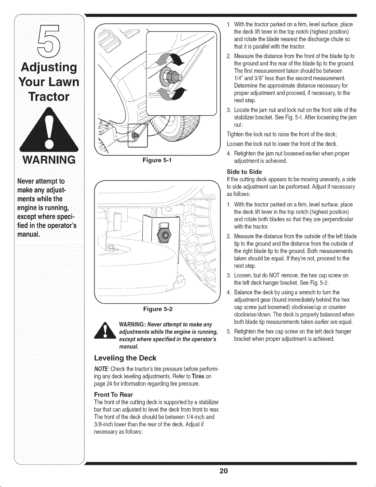
3. Locatethejam nutandlocknut onthe frontsideof the
stabilizerbracket.SeeFig.5-1.After looseningthejam
nut:
Tightenthe locknutto raisethefrontof the deck;
Loosenthe locknut to lowerthefront of the deck.
4. Retightenthe jam nut loosenedearlierwhen proper
adjustmentis achieved.
Side to Side
If the cuttingdeck appearsto bemowingunevenly,a side
to side adjustmentcan beperformed.Adjustif necessary
as follows:
.
Withthe tractorparkedon a firm,levelsurface,place
the decklift leverin the top notch(highestposition)
androtateboth bladesso thattheyareperpendicular
withthe tractor.
2. Measurethe distancefromthe outsideof the leftblade
tip to the groundandthe distancefromtheoutsideof
the rightbladetip to theground.Bothmeasurements
takenshouldbeequal. Ifthey'renot,proceedto the
nextstep.
3. Loosen,butdo NOT remove,the hexcap screwon
the leftdeckhangerbracket.SeeFig. 5-2.
4. Balancethe deckby usingawrenchto turn the
adjustmentgear(foundimmediatelybehindthe hex
cap screwjust loosened)clockwise/upor counter-
clockwise/down.Thedeckis properlybalancedwhen
bothbladetip measurementstakenearlierareequal.
5. Retightenthe hex capscrewonthe left deck hanger
bracketwhenproperadjustmentis achieved.
Leveling the Deck
NOTE:Checkthe tractor'stire pressurebeforeperform-
inganydeck levelingadjustments.Referto Tires on
page24 for informationregardingtire pressure.
Front To Rear
Thefrontof the cuttingdeckis supportedbya stabilizer
barthatcanadjustedto levelthe deckfromfrontto rear.
Thefrontof the deckshouldbebetween1/4-inchand
3/8-inchlowerthanthe rearof the deck.Adjustif
necessaryas follows:
2O
Parking Brake Adjustment
WARNING:Neverattempt to adjust the
brakes while the engine is running. Always
disengage PTO,move shift lever into
neutral position, stop engine and remove
key to prevent unintended starting.
Ifthe tractordoesnot cometo a completestopwhenthe
brakepedalis completelydepressed,or if the tractor's
rearwheelscan rollwiththe parkingbrakeapplied,the
brakeis in need of adjustment.See an authorizedMTD
ServiceDealerto haveyourbrakesproperlyadjusted.
Seat Adjustment
NOTE:For shippingreasons,seatsare eitherfastened
to the tractorseat'spivotbracketwith a plastictie, or
mountedbackwardto thepivotbracket.Ineither case,
free the seatformits shippingpositionand removethe
two hexscrews(or knobs,on modelssoequipped)from
the bottomof seatbeforeproceedingwith applicable
instructions.
_ ARNING:Before operating this machine,
make sure the seat is engaged in the seat
stop, stand behind the machine and pull
back on seat until fully engaged into stop.
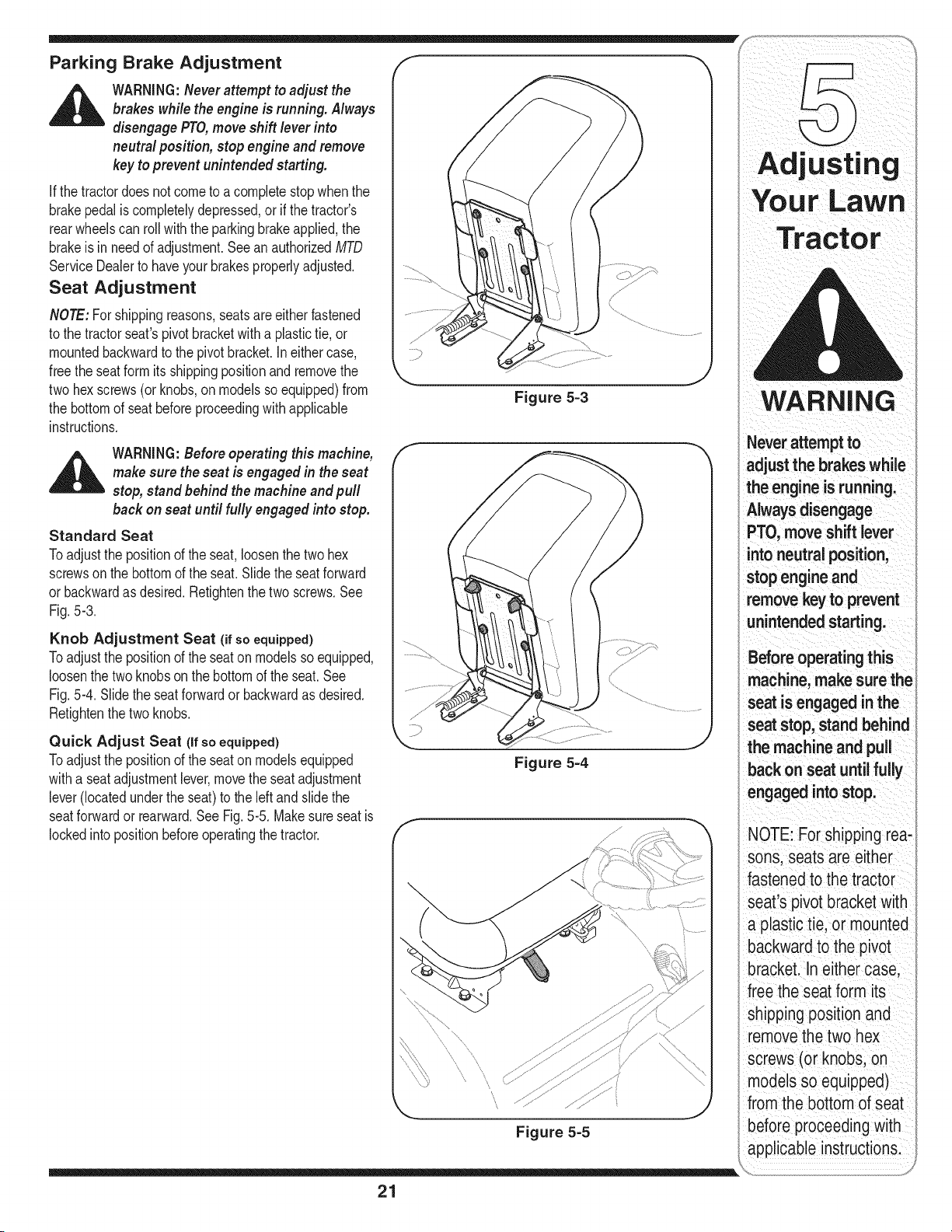
Standard Seat
Toadjustthe positionof the seat,loosenthe two hex
screwson the bottomof the seat.Slide the seatforward
or backwardas desired.Refightenthe two screws.See
Fig.5-3.
Knob Adjustment Seat (if so equipped)
Toadjustthe positionof the seaton modelsso equipped,
loosenthe twoknobson the bottomof theseat. See
Fig.5-4. Slidethe seatforwardor backwardas desired.
Retightenthe twoknobs.
Quick Adjust Seat (if so equipped)
Toadjustthe positionof the seaton modelsequipped
witha seat adjustmentlever,movethe seatadjustment
lever(locatedundertheseat)to the leftand slidethe
seatforwardor rearward.See Fig. 5-5. Makesureseat is
lockedintopositionbeforeoperatingthe tractor.
Figure 5=3
Figure 5=4
Figure 5=5
Adjusting
WARNING
Never attemptto
adjust the brakes while
the engineis running.
Alwaysdisengage
PTO,move shift lever
intoneutral position,
stopengine and
remove key to prevent
unintended starting.
Before operating this
machine, make sure the
seat is engaged in the
seat stop, stand behind
the machine and pull
back on seat until fully
engaged intostop.
NOTE: For shipping rea-
sons, seats are either
fastened to the tractor
;eat's pivot bracket with
olastic tie, or mounted
backward to the pivot
bracket. In either case,
free the seat form its
shipping position and
removethe two hex
screws (or knobs, on
models so equipped)
from the bottom of seat
before proceeding with
applicable instructions.
21
Tractor
WARNING
aBeforeperforming
ny maintenance or
repairs, disengage
PTO, move shift lever
into neutral position,
set parking brake, stop
engine and remove key
to prevent unintended
starting.
Before lubricating,
repairing, or inspect-
ing, always disengage
PTO, move shift lever
into neutral position,
set parking brake, stop
engine and remove key
to prevent unintended
starting.
\
_S Single ........
J
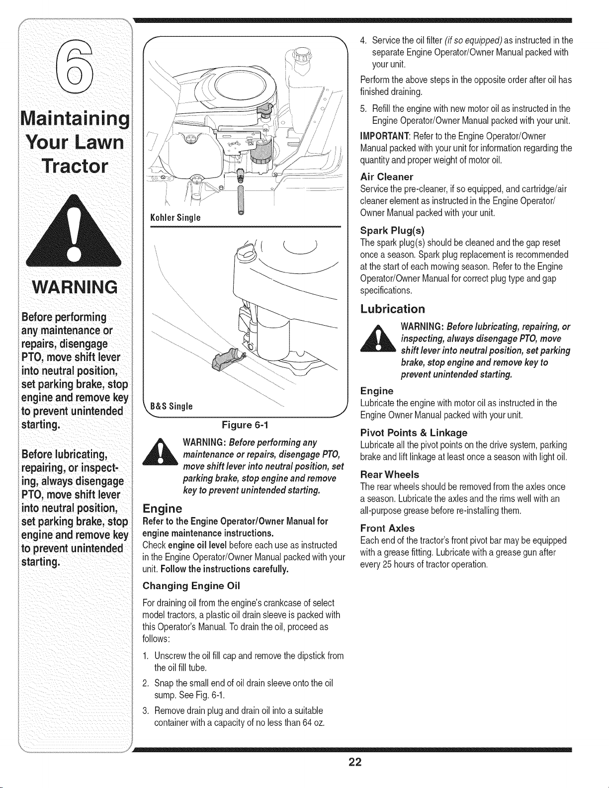
Figure 6=1
_ WARNING:Before performingany
maintenance or repairs,disengagePTO,
moveshift lever into neutral position, set
parking brake,stop engine and remove
key to prevent unintended starting.
Engine
Referto the EngineOperator/Owner Manualfor
enginemaintenance instructions.
Checkengineoil level beforeeachuseas instructed
inthe EngineOperator/OwnerManualpackedwithyour
unit.Follow the instructionscarefully.
Changing Engine Oil
Fordrainingoilfromthe engine'scrankcaseof select
modeltractors,a plasticoildrainsleeveis packedwith
thisOperator'sManual.Todrainthe oil, proceedas
follows:
.
2.
3.
Unscrewthe oilfill capand removethe dipstickfrom
theoil fill tube.
Snapthe smallendof oildrainsleeveontothe oil
sump.SeeFig.6-1.
Removedrainpluganddrainoil intoa suitable
containerwitha capacityof no lessthan64oz.
4. Servicethe oilfilter (if so equipped)as instructedin the
separateEngineOperator/OwnerManualpackedwith
yourunit.
Performthe abovestepsinthe oppositeorderafteroil has
finisheddraining.
5. Refillthe enginewith newmotoroil as instructedinthe
EngineOperator/OwnerManualpackedwithyour unit.
IMPORTANT:Referto the EngineOperator/Owner
Manualpackedwithyourunit for informationregardingthe
quantityandproperweightof motoroil.
Air Cleaner
Servicethe pre-cleaner,if soequipped,andcartridge/air
cleanerelementas instructedin the EngineOperator/
OwnerManualpackedwith your unit.
Spark Plug(s)
Thesparkplug(s)shouldbecleanedand thegap reset
oncea season.Sparkplugreplacementis recommended
at the startof each mowingseason.Referto the Engine
Operator/OwnerManualfor correctplug type and gap
specifications.
Lubrication
,_ WARNING:Before lubricating, repairing, or
inspecting, always disengage PTO,move
shift lever into neutral position, set parking
brake, stop engine and remove key to
prevent unintended starting.
Engine
Lubricatethe enginewithmotoroil as instructedin the
EngineOwnerManualpackedwith yourunit.
Pivot Points & Linkage
Lubricateall the pivotpoints on the drivesystem,parking
brakeand lift linkageat least oncea seasonwithlightoil.
Rear Wheels
The rearwheelsshouldbe removedfrom the axles once
a season.Lubricatethe axles and the rimswell with an
all-purposegreasebeforere-installingthem.
Front Axles
Eachendof the tractor'sfrontpivot bar may be equipped
witha greasefitting. Lubricatewith a greasegun after
every25 hoursof tractoroperation.
22
Cleaning the Engine And Deck
Anyfuel oroil spilledon the machineshouldbe wiped
off promptly.DoNOT allowdebristo accumulatearound
thecoolingfinsof the engineor on any otherpart of the
machine.
iMPORTANT:The useof a pressurewasherto clean
yourtractoris NOTrecommended.It may causedamage
to electricalcomponents,spindles,pulleys,bearingsor
theengine.
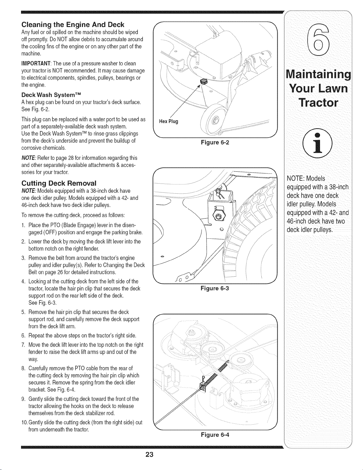
Deck Wash System TM
A hexplug can be foundon yourtractor'sdecksurface.
SeeFig.6-2.
Thisplugcanbe replacedwith a waterport to beusedas HexPlug
part of a separately-availabledeck wash system.
Usethe DeckWashSystemTM to rinsegrassclippings k,,,,
fromthe deck'sundersideand preventthe buildupof
corrosivechemicals.
NOTE:Referto page28for informationregardingthis
andotherseparately-availableattachments& acces-
soriesfor yourtractor.
Cutting Deck Removal
NOTE:Modelsequippedwitha 38-inchdeck have
onedeckidlerpulley.Modelsequippedwitha 42- and
46-inchdeckhavetwo deck idler pulleys.
To removethecuttingdeck, proceedas follows:
1. Placethe PTO(BladeEngage)leverinthe disen-
gaged(OFF)positionandengagethe parkingbrake.
2. Lowerthe deckby movingthedeck lift leverintothe
bottomnotchonthe rightfender.
3. Removethe beltfromaroundthetractor'sengine
pulleyandidlerpulley(s).Referto Changingthe Deck
Belton page26 for detailedinstructions.
4. Lookingat the cuttingdeckfromtheleft sideof the
tractor,locatethe hairpinclip thatsecuresthe deck
supportrodon the rear left sideof the deck.
SeeFig.6-3.
5. Removethe hairpin clipthat securesthedeck
supportrod, andcarefullyremovethe decksupport
fromthe decklift arm.
6. Repeattheabovestepson thetractor'srightside.
7. Movethe decklift leverintothe top notchon the right
fenderto raisethe decklift arms up and out of the
way.
8. Carefullyremovethe PTOcablefrom the rearof
thecutting deckby removingthe hair pinclip which
securesit. Removethe springfrom the deck idler
bracket.See Fig.6-4.
9. Gentlyslidethe cuttingdecktowardthe frontof the
tractorallowingthe hooksonthe deckto release
themselvesfromthe deckstabilizerrod.
10.Gentlyslidethe cuttingdeck (from the rightside)out
fromunderneaththe tractor.
Figure 6=2
Figure 6=3
F
Figure 6-4
23
Your LaWn
i
NOTE: Models
equippedwith a 38-inch
deck have one deck
idler pulley.Models
)quipped with a 42- and
46-inch deck have two
deck idlerpulleys.
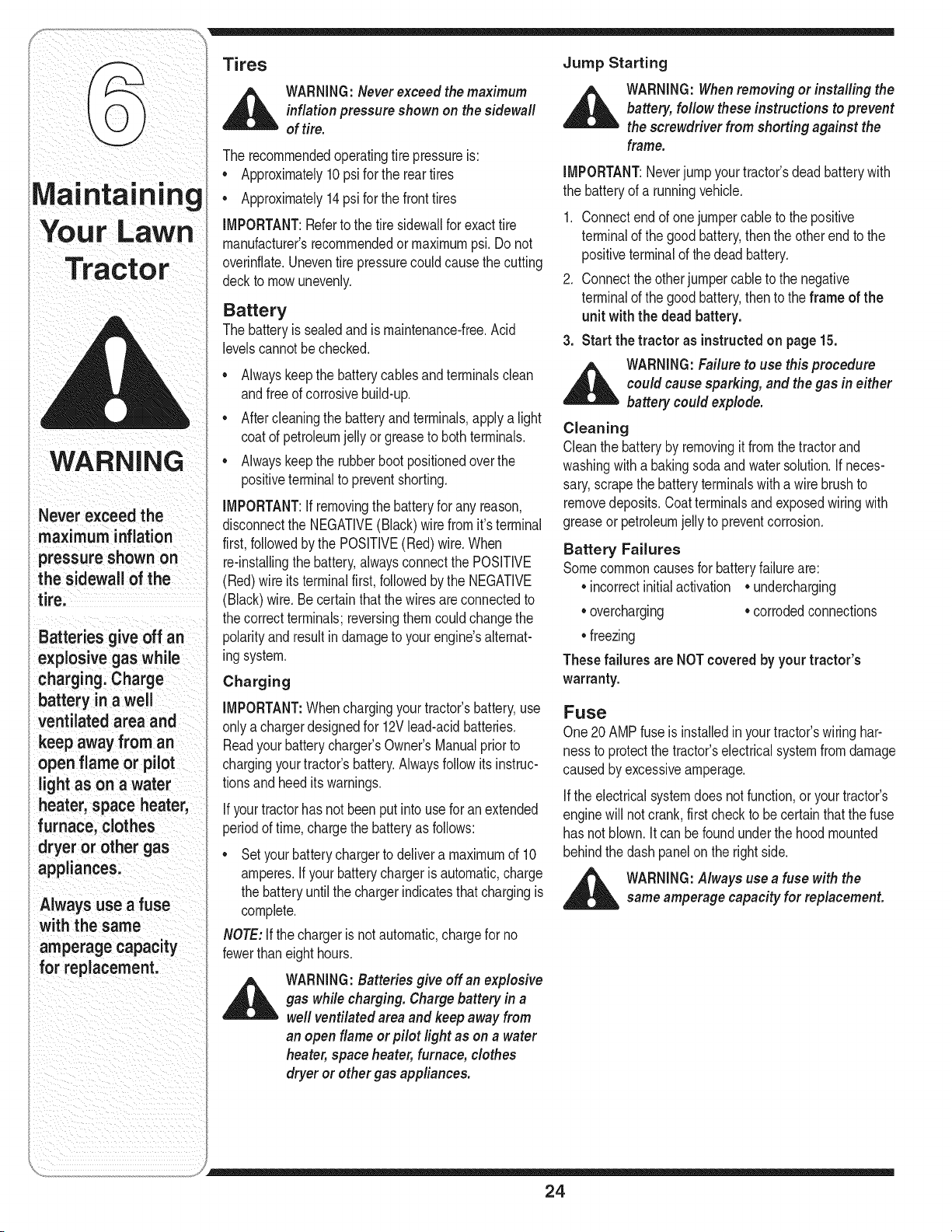
Tires
_ ARNING:Neverexceed the maximum
inflation pressure shown on the sidewall
of tire.
The recommendedoperatingtire pressureis:
• Approximately10 psifor the rear tires
Ma| !ltal n !ng • Approximately14psi for the fronttires
|_iAlllt MPORTANTI aefertothetresdewa forexactt re
,, ,_,,,,_ _ ,,,,,_,_vv,, • manufacturersrecommendedormaximumpsi.Do not
Tractor
WARNING
Never exceed the
maximum inflation
pressure shown on
the sidewall of the
tire.
Batteries give off an
explosive gas while
charging. Charge
battery in a well
ventilated area and
keep away from an
open flame or pilot
light as on a water
heater, space heater,
furnace, clothes
dryer or other gas
appliances.
Always use a fuse
with the same
amperage capacity
for replacement.
overinflate.Uneventirepressurecouldcausethe cutting
deckto mowunevenly.
Battery
The batteryis sealedand is maintenance-free.Acid
levelscannotbechecked.
• Alwayskeepthe batterycablesand terminalsclean
andfreeof corrosivebuild-up.
• Aftercleaningthe batteryand terminals,apply a light
coatof petroleumjelly or greaseto bothterminals.
• Alwayskeepthe rubberboot positionedoverthe
positiveterminalto preventshorting.
IMPORTANT:Ifremovingthe batteryfor anyreason,
disconnectthe NEGATIVE(Black)wire fromit'sterminal
first,followedby the POSITIVE(Red)wire.When
re-installingthe battery,alwaysconnectthe POSITIVE
(Red)wire itsterminalfirst, followedby the NEGATIVE
(Black)wire.Becertainthatthewiresareconnectedto
thecorrectterminals;reversingthemcouldchangethe
polarityandresultindamageto your engine'salternat-
ingsystem.
Charging
IMPORTANT:Whenchargingyour tractor'sbattery,use
onlya chargerdesignedfor 12Vlead-acidbatteries.
Readyourbatterycharger'sOwner'sManualpriorto
chargingyourtractor'sbattery.Alwaysfollowitsinstruc-
tionsand heeditswarnings.
If yourtractorhasnot been put intousefor an extended
periodof time,chargethe batteryas follows:
• Setyour batterychargerto delivera maximumof 10
amperes.Ifyour batterychargeris automatic,charge
the batteryuntilthe chargerindicatesthat chargingis
complete.
NOTE:Ifthe chargeris notautomatic,chargefor no
fewerthaneight hours.
_ ARNING:Batteries give off an explosive
gas while charging. Charge battery in a
well ventilated areaand keep away from
an open flame or pilot light as on a water
heater,space heater, furnace, clothes
dryer or other gas appliances.
Jump Starting
_ ARNING: Whenremoving or installing the
battery, follow these instructions to prevent
the screwdriver from shorting against the
frame.
IMPORTANT:Neverjump yourtractor'sdeadbatterywith
the batteryof a runningvehicle.
1. Connectendof onejumpercableto the positive
terminalof the goodbattery,thenthe otherendto the
positiveterminalof the deadbattery.
2. Connectthe otherjumpercable to the negative
terminalof the goodbattery,thento the frame of the
unit with the dead battery.
3. Start the tractor as instructedon page15.
_ ARNING: Failure to use this procedure
could cause sparking, and thegas in either
battery could explode.
Cleaning
Cleanthe batteryby removingit fromthe tractorand
washingwitha bakingsodaand water solution.If neces-
sary,scrapethe batteryterminalswith a wire brushto
removedeposits.Coatterminalsandexposedwiringwith
greaseor petroleumjelly to preventcorrosion.
Battery Failures
Somecommoncausesfor batteryfailureare:
• incorrectinitialactivation • undercharging
• overcharging • corrodedconnections
• freezing
These failures are NOTcovered by your tractor's
warranty.
Fuse
One20AMPfuseis installedin yourtractor'swiring har-
nessto protectthe tractor'selectricalsystemfromdamage
causedby excessiveamperage.
If the electricalsystemdoes notfunction,oryourtractor's
enginewill notcrank,first checkto be certainthat the fuse
has notblown.Itcan befoundunderthehoodmounted
behindthe dashpanelon the rightside.
_ WARNING:Always use a fuse with the
same amperage capacity for replacement.
24
Cutting Blades
,_ WARNING:Besure to shut the engine
off, remove ignition key,disconnect the
spark plug wire(s) and ground against
the engine to prevent unintended starting
before removing the cutting blade(s) for
sharpening or replacement. Protect your
hands by using heavy gloves or a rag to
grasp the cutting blade.
WARNING:Periodically inspect the blade
spindles for cracks or damage, especially
if you strike a foreign object. Replace
immediately if damaged.
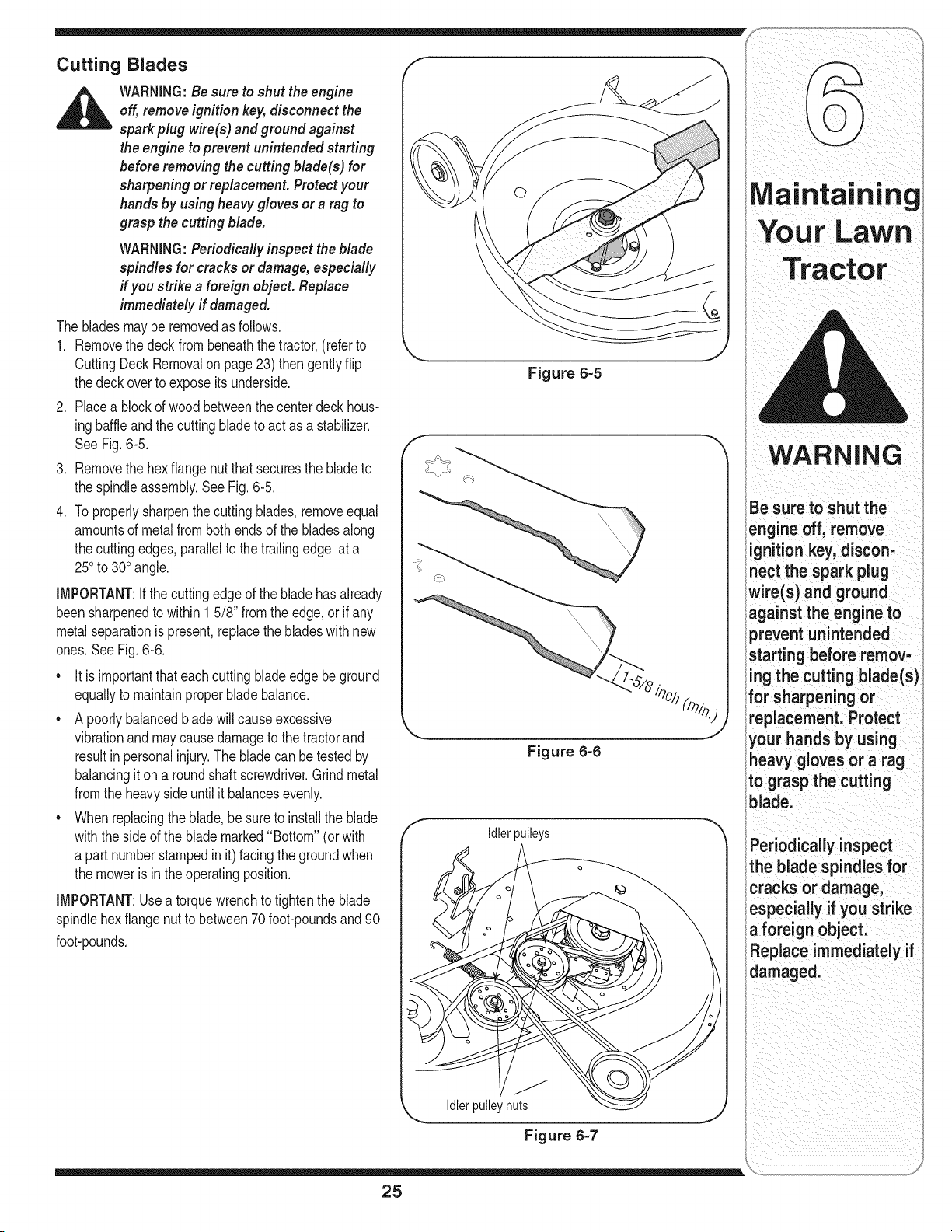
The bladesmayberemovedas follows.
1. Removethe deckfrombeneaththe tractor,(referto
CuttingDeckRemovalon page23) thengentlyflip
thedeckoverto exposeitsunderside•
2. Placea blockof wood betweenthe centerdeck hous-
ingbaffleandthe cuttingbladeto act as a stabilizer.
SeeFig.6-5.
3. Removethe hexflangenutthat securesthe bladeto
the spindleassembly.See Fig.6-5.
4. Toproperlysharpenthe cuttingblades,removeequal
amountsof metalfrombothends of the bladesalong
thecutting edges,parallelto the trailingedge,at a
250to 300angle.
IMPORTANT:Ifthe cuttingedgeof the bladehasalready
beensharpenedto within1 5/8" from theedge,or if any
metalseparationis present,replacethe bladeswith new
ones.SeeFig.6-6.
• It is importantthateachcuttingbladeedgebeground
equallyto maintainproperbladebalance•
• A poorlybalancedbladewill causeexcessive
vibrationand maycausedamageto thetractorand
resultinpersonalinjury.The bladecan betestedby
balancingit ona roundshaftscrewdriver.Grind metal
fromthe heavysideuntil it balancesevenly.
• Whenreplacingtheblade,be sureto installthe blade
withthe sideof the blademarked"Bottom" (orwith
a part numberstampedinit) facingthe groundwhen
the moweris inthe operatingposition.
IMPORTANT:Usea torquewrenchto tighten the blade
spindlehexflangenutto between70foot-poundsand90
foot-pounds.
f
Figure 6-5
f
\\\\
Idlerpulleys
Idler pulleynuts
Figure 6-7
25
Maintaining
WARNING
Be sure to shut the
engine off, remove
ignition key, discon-
nect the spark plug
wire(s) and ground
against the engine to
prevent unintended
irting before remov-
the cutting blade(s)
for sharpening or
replacement. Protect
your hands by using
heavy gloves or a rag
to grasp the cutting
blade.
Periodically inspect
the blade spindles for
cracks or damage,
especially ifyou strike
a foreign object.
_laceimmediately if
damaged.
WARNING
Be sure to shut the
engine off, remove
ignition key, d iscon-
nect the spark plug
wire(s) and ground
against the engine to
prevent unintended
starting before remov=
ing the belt.
Avoid the possibility of
a pinching injury. Do
not place your fingers
on the idler spring or
between the belt and a
pulleywhile removing
the belt.
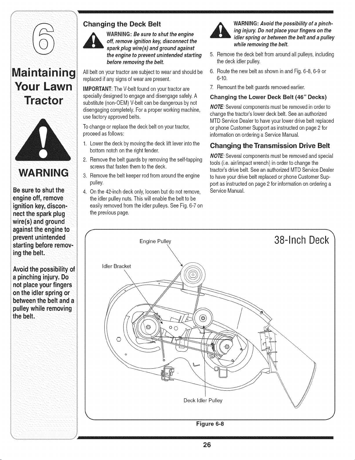
Changing the Deck Belt
WARNING:Besure to shut the engine
off,removeignition key,disconnect the
spark plug wire(s) and ground against
the engine to prevent unintended starting
before removing the belt.
All belton yourtractorare subjectto wearand shouldbe
replacedif any signsof wearare present.
IMPORTANT:TheV-beltfoundon yourtractorare
speciallydesignedto engageand disengagesafely.A
substitute(non-OEM)V-beltcan bedangerousby not
disengagingcompletely.Fora properworkingmachine,
usefactoryapprovedbelts.
Tochangeor replacethe deckbelt onyourtractor,
proceedas follows:
1. Lowerthe deckby movingthe deck lift leverintothe
bottomnotchonthe rightfender.
2. Removethe beltguardsby removingthe self-tapping
screwsthatfastenthemto the deck.
.
4.
Removethe beltkeeperrodfromaroundthe engine
pulley.
Onthe 42-inchdeckonly,loosenbut do not remove,
the idlerpulleynuts.This will enablethe belt to be
easilyremovedfromthe idlerpulleys.See Fig. 6-7 on
the previouspage.
_1= ARNING:Avoid the possibilityofa pinch-
ing injury. Do not placeyour fingers on the
idler spring or between the belt and a pulley
while removing the belt.
5. Removethedeckbelt fromaroundall pulleys,including
the deckidlerpulley.
6. Routethe newbelt as shownin and Fig.6-8, 6-9 or
6-10.
7. Remountthe beltguardsremovedearlier.
Changing the Lower Deck Belt (46" Decks)
NOTE:Severalcomponentsmustbe removedin orderto
changethe tractor'slowerdeck belt.Seean authorized
MTDServiceDealerto haveyourlowerdrivebelt replaced
or phoneCustomerSupportas instructedon page2 for
informationonorderinga ServiceManual.
Changing the Transmission Drive Belt
NOTE:Severalcomponentsmustbe removedandspecial
tools(i.e.air/impactwrench)inorderto changethe
tractor'sdrive belt.Seean authorizedMTDServiceDealer
to haveyourdrivebelt replacedor phoneCustomerSup-
portas instructedonpage2 for informationon orderinga
ServiceManual.
f
Idler Bracket
Engine Pulley
\
38-Inch Deck
©
o
b
Deck Idler Pulley
Figure 6=8
26
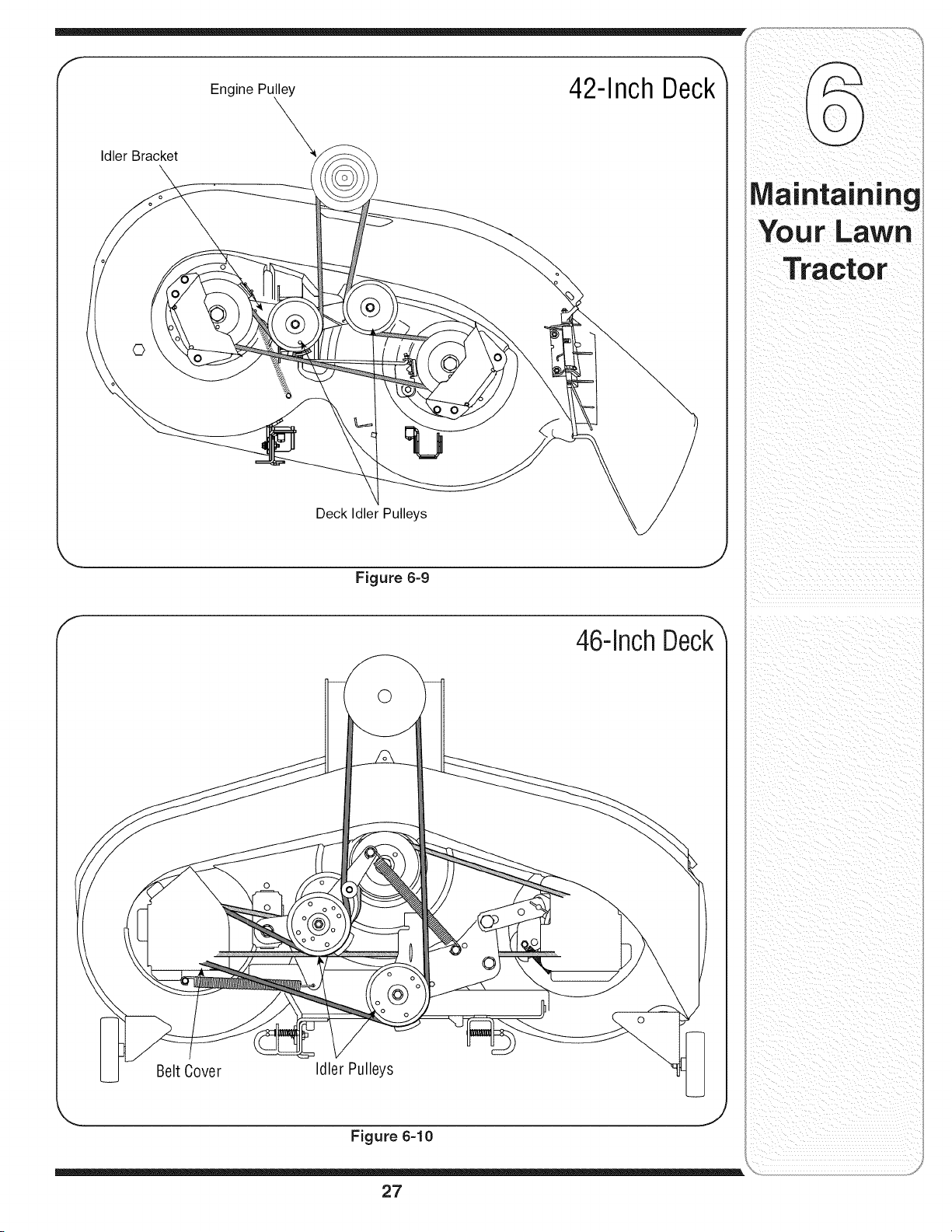
Idler Bracket
Engine Pulxley
\
42-Inch Deck_
©
Deck Idler Pulleys
.. .j
Figure 6=9
46-inch Deck_
0
©
Belt Cover Idler Pulleys
J
Figure 6=10
27
Tractor
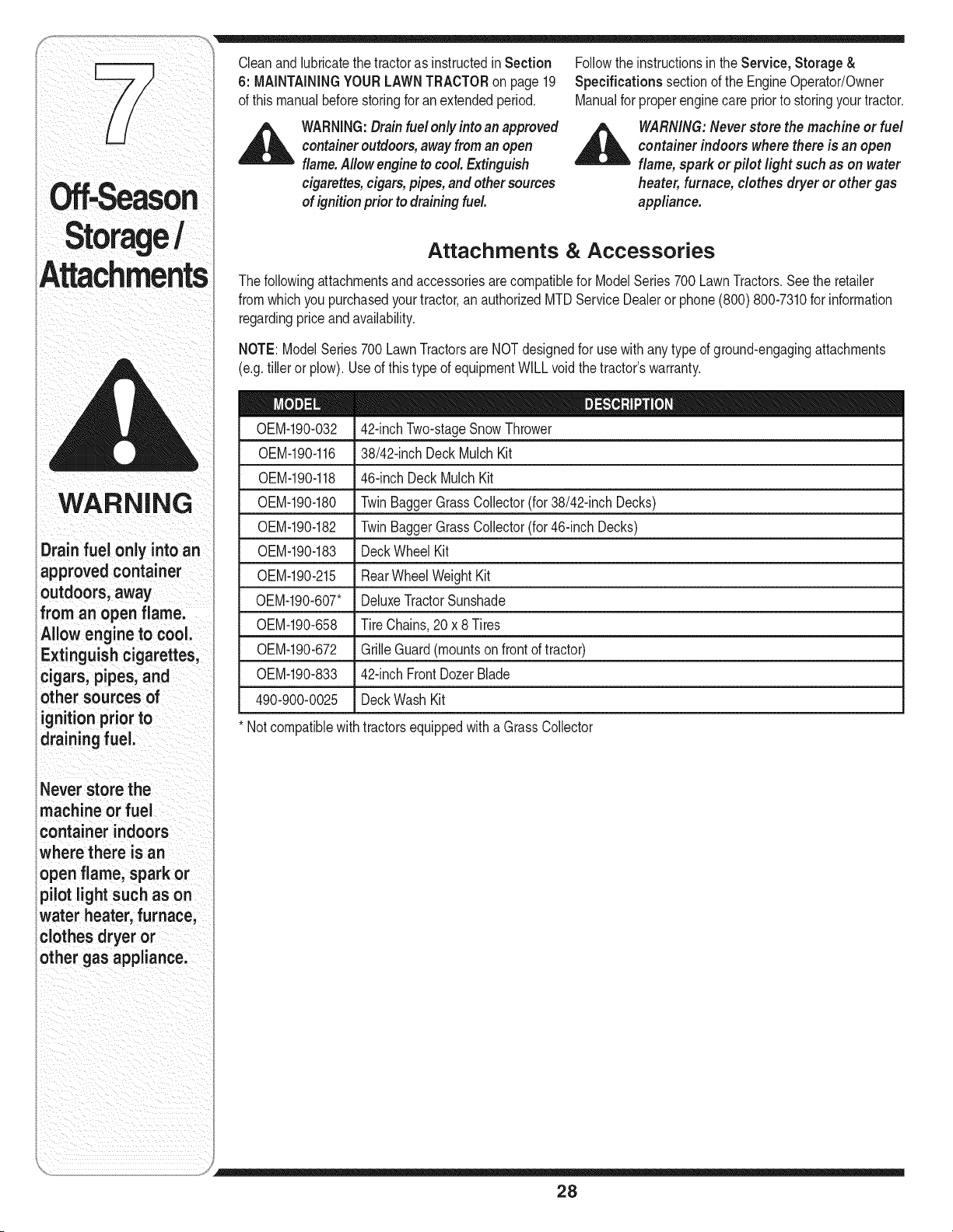
Attachments
WARNING
i Drain fuel only into an
approvedcontainer
outdoors,away
fromanopenflame.
Allow engine to cool.
Extinguishcigarettes,
cigars, pipes, and
other sources of
ignitionpriorto
drainingfuel.
i Neverstorethe
imachine orfuel
icontainerindoors
wherethere isan
openflame, sparkor
ipilotlightsuchas on
_waterheater,furnace,
iclothesdryeror
iothergas appliance.
Cleanandlubricatethe tractoras instructedin Section Followthe instructionsin the Service, Storage &
6: MAiNTAiNiNGYOURLAWNTRACTORon page19 Specifications sectionof the EngineOperator/Owner
of thismanualbeforestoringfor an extendedperiod. Manualfor properenginecare priorto storingyourtractor.
,_ WARNING:Drainfuel only into anapproved
containeroutdoors,awayfromanopen
flame.Allow engineto cool Extinguish
cigarettes,cigars,pipes, and other sources
of ignition prior to drainingfuel.
_ ARNING: Neverstore the machine or fuel
container indoors where there is an open
flame, spark or pilot light such as on water
heater,furnace, clothes dryer or other gas
appliance.
Attachments & Accessories
Thefollowingattachmentsandaccessoriesarecompatiblefor ModelSeries700 LawnTractors.Seethe retailer
fromwhichyou purchasedyourtractor,an authorizedMTDServiceDealeror phone(800) 800-7310for information
regardingpriceandavailability.
NOTE:ModelSeries700LawnTractorsare NOTdesignedfor usewith any type of ground-engagingattachments
(e.g.tiller or plow). Useof this type of equipmentWILL voidthe tractor'swarranty.
0EM-190-032 42-inchTwo-stageSnowThrower
0EM-190-116
0EM-190-118
0EM-190-180
0EM-190-182
0EM-190-183
0EM-190-215
0EM-190-607"
0EM-190-658
0EM-190-672
0EM-190-833
490-900-0025
* Notcompatiblewith
38/42-inchDeck MulchKit
46-inch DeckMulchKit
TwinBaggerGrassCollector(for 38/42-inchDecks)
TwinBaggerGrassCollector(for 46-inchDecks)
DeckWheel Kit
RearWheelWeightKit
DeluxeTractorSunshade
Tire Chains,20x 8 Tires
GrilleGuard(mountsonfrontof tractor)
42-inchFrontDozerBlade
DeckWashKit
tractorsequippedwitha Grass Collector
28
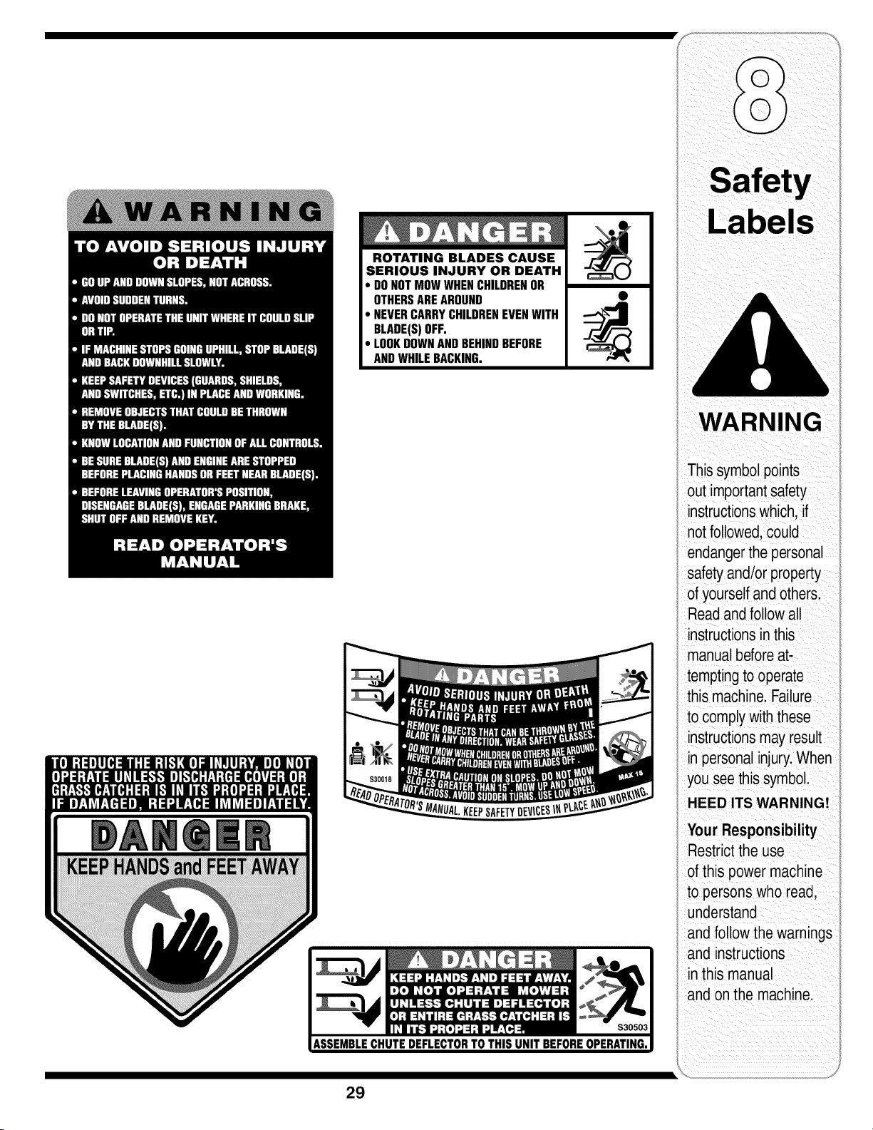
ROTATING BLADES CAUSE
SERIOUS INJURY OR DEATH
• DONOTMOWWHENCHILDRENOR
OTHERSAREAROUND
• NEVERCARRYCHILDRENEVENWITH
BLADE(S)OFF.
• LOOKDOWNANDBEHINDBEFORE
ANDWHILEBACKING.
KEEPSAFETY
WARNING
This symbol points
out importantsafety
instructionswhich, if
notfollowed,could
endangerthe personal
safety and/or property
of yourselfand others.
Readand follow all
instructionsinthis
manual beforeat-
temptingto operate
this machine. Failure
to complywith these
instructionsmay result
in personalinjury.When
you see this symbol.
HEED ITS WARNING!
Your Responsibility
Restrictthe use
of this power machine
to persons who read,
understand
and follow the warnings
and instructions
in this manual
and on the machine.
29

Trou
Shootin
For repairs
beyond the minor
adjustments listed
here, contact an
i authorized service
dealer.
Pro bl e m Ca use Remedy
Eng ne fa s to start 1. PTOengaged 1 PlacePTOknob (or lever)in
disengaged(OFF)postion.
2. Sparkplugwire(s)disconnected. 2. Connectwire(s) to spark plug(s).
3. Fue tankemptyor stae fue . 3. F tank w th c can fresh gaso ne
4 Chokenot act vated 4. Pullout the CHOKEcontrol (if so
• " equipped)orplacethe throttle
controlinCHOKEposition.
5. Faultysparkplug. 5. Clean,adjustgap,or replace.
6. Blockedfuel hne. 6. Cleanfuel I neor replacefuelfilter,
7. Engineflooded, if so equipped.
7. Crankenginewiththrottle in FAST
position.
8 Parkingbrakenotengaged. 8. Engageparkingbrake.
9. Throttlecontrollevernotin correct 9. Placethrottleleverto FAST
startingposition, position.
Engineruns erratic
1. UnitrunningwithCHOKEapplied.
2. Sparkplugwire(s)loose.
3. Blockedfuellineor stale fuel.
4. Ventingas cap plugged.
5. Waterordirt infuel system.
6. Dirty aircleaner.
1. PushCHOKEcontrol(if so
equipped)in, or movethe throttle
controlout of the CHOKEposition.
2. Connectandtightenspark
plugwire(s).
3. Cleanfuel line;fill tankwithclean,
fresh(lessthan30 daysold)
gasoline.Replacefuel filter,if so
equipped.
4. Clearventor replaceif damaged.
5. Drainfuel tank. Refillwith
freshfuel.
6. Replaceair cleanercartridge/ele-
mentorclean pro-cleaner,if so
equipped.
_ J
3O

Problem Cause Remedy
ne overheats 1} Engineoil levelIowl Fill crankcasewith properoil.
21 Air flowrestricted. 2. C!eangrassclippingsanddebrs
from aroundtheengineScoo!ing
fins and blowerhousing.
Enginehesitates at 1. Sparkplug(s)gap tooclose. 1. Removesparkplug(s)and reset
high RPM the gap.
des poor i sPark p!ug(s)fou ed faulty or Replace Spaikp!ug(S):Set plug(s)
too Wide; gapl
2 Dirtyair c!eaner. 2 Replaceair cleanercartridgeiele_
mentor cleanpre:cleaner,if S0
equipped.
Excessive 1. Cuttingbladelooseor unbalanced. 1. Tightenbladeandspindle.
Vibration Balanceblade.
2. Damagedor bentcuttingblade. 2. Replaceblade.
Mower wili not EnginesPeedtoo Iowl li PlaCethrottle Controlin FAST
much grass Wet giass (rabbit)p0siti°n,
(mode1s equipped .... 2 Do not mowwhengrass iswet;.
with mu/ il'kJt _ watunt atertocut
a c 3 Excessivelyhighgrass: _ ; :_ . .
_. Ivlowonce al a nigh cumnghe!gnu,
then mow againat desiredheight
........................ oimake a nar[owercuttingpathI
4.1Dullblade: &sharpen or replaceblade:
Uneven cut
1. Decknotbalancedproperly. 1. Performside-to-sidedeckadjust-
2. Dullblade, ment.
2. Sharpenor replaceblade.
3. Uneventire pressure.
3. Checktire pressureinall four
tires.
31
U
ii ii
Forrepairs
beyond the minor
adjustments listed
here, contact an
rthorized service
dealer.
_iii_i_ _ ii_i _ i ii_ ii}
i _ ii_ _ i_ii ii I
ii _ i i
i iii ii _ i i
i i
ii i!_ii_ii_i_ii_!iI i iiiiiiii_iii I
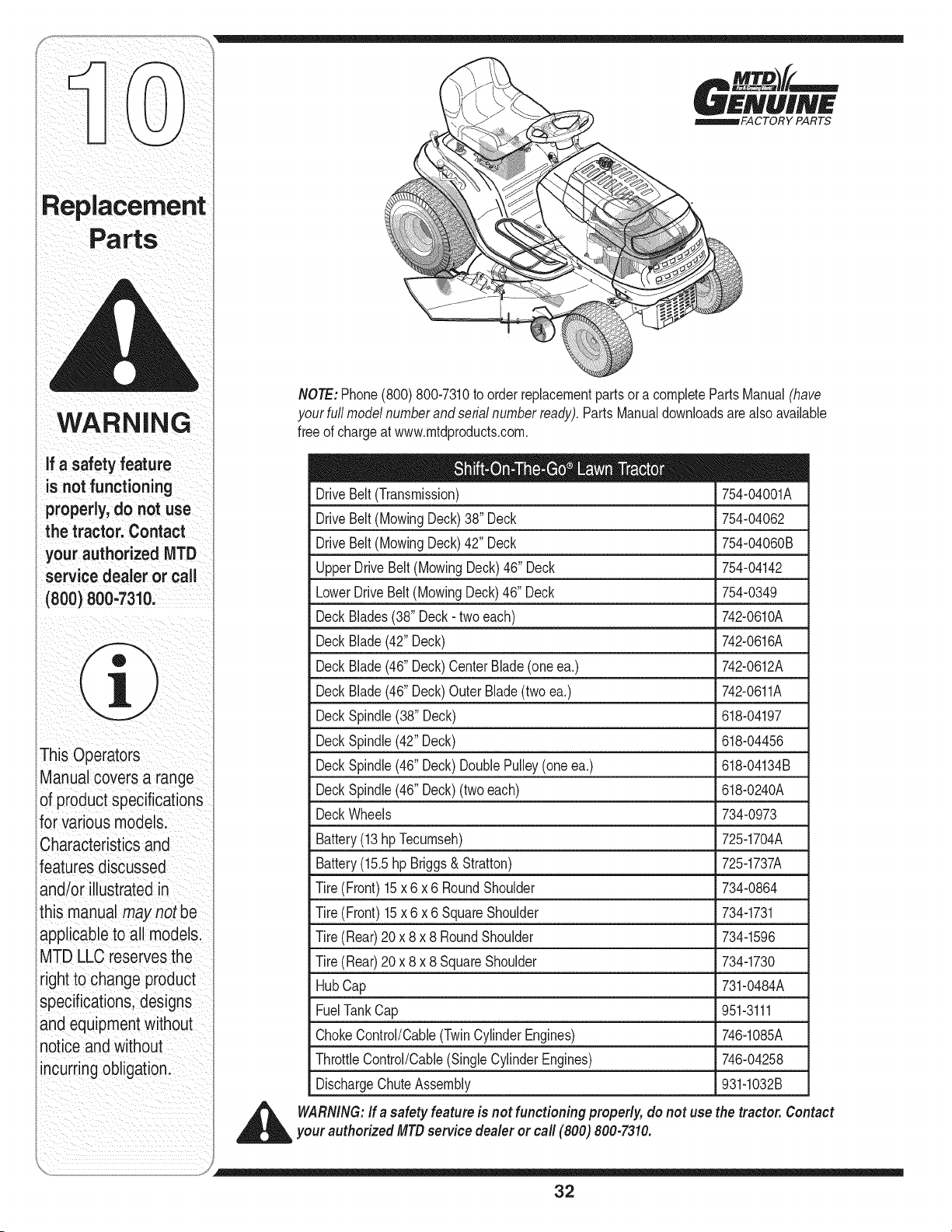
WARNING
a safety feature
isnotfunctioning
properly, do not use
the tractor.Contact
your authorized MTD
servicedealeror call
8oo)800,73 oi
This Operators
ManUalCoversa range
of product specifiCations
for Variousmodels:
CharaCteristicsand
featuresdiscussed
and/or illustrated in
this manual maynot
appliCable to al models:
MTD LLC reservesthe
rightto ChangeprOduCt
specifications designs
and equipmentwithout
notiCeand Without
incurring obligation.
_FACTORY PARTS
NOTE:Phone(800)800-7310to orderreplacementpartsor a completePartsManual(have
your fullmodelnumberandserialnumberready).PartsManualdownloadsare also available
free of chargeat www.mtdproducts.com.
DriveBelt (Transmission) 754-04001A
DriveBelt (MowingDeck)38" Deck 754-04062
DriveBelt (MowingDeck)42" Deck 754-04060B
UpperDriveBelt (MowingDeck)46" Deck 754-04142
LowerDriveBelt(MowingDeck)46" Deck 754-0349
DeckBlades(38"Deck- two each) 742-0610A
DeckBlade(42" Deck) 742-0616A
DeckBlade(46" Deck)CenterBlade(oneea.) 742-0612A
DeckBlade(46" Deck)Outer Blade(twoea.) 742-0611A
DeckSpindle(38" Deck) 618-04197
DeckSpindle(42"Deck) 618-04456
DeckSpindle(46"Deck)DoublePulley(one ea.) 618-04134B
DeckSpindle(46"Deck)(two each) 618-0240A
DeckWheels 734-0973
Battery(13hpTecumseh) 725-1704A
Battery(15.5hp Briggs& Stratton) 725-1737A
Tire(Front)15x 6x 6 RoundShoulder 734-0864
Tire(Front)15x 6x 6 SquareShoulder 734-1731
Tire(Rear)20x 8x 8 RoundShoulder 734-1596
Tire(Rear)20x 8x 8 SquareShoulder 734-1730
HubCap 731-0484A
FuelTankCap 951-3111
ChokeControl/Cable(TwinCylinderEngines) 746-1085A
ThrottleControl/Cable(SingleCylinderEngines) 746-04258
DischargeChuteAssembly 931-1032B
_ ARNING:If a safety featureis notfunctioningproperly, do not use the tractor. Contact
your authorized MTDservice dealer or call (800) 800-7310.
32

NOTES
Use this page to make notes and write down important information.
33
CALIFORNIA EMISSION CONTROL WARRANTY STATEMENT
YOUR WARRANTY RIGHTS AND OBLIGATIONS
The CaliforniaAir ResourcesBoardandMTDConsumerGroup Inc are pleasedto explaintheevaporativeemissioncontrolsystemwarrantyon your 2007lawn
mower.In California,new lawnmowermust be designed,builtand equippedto meet the State'sstringentanti-smogstandards.MTDConsumerGroupInc must
warrantthe EECSon yourlawn mowerfor the periodof time listedbelow providedthere has beenno abuse,neglector impropermaintenanceof your lawnmower.
Your EECSmayincludeparts such as the carburetor,fuel-injectionsystem,the ignitionsystem,catalyticconverter,fuel tanks,fuel lines,fuel caps,valves,
canisters,filters,vaporhoses,clamps,connectors,and other associatedemission-relatedcomponents.
Where a warrantable condition exists, MTDConsumer Group Inc will repair your lawn mower at no cost to you includingdiagnosis, parts and labor.
MANUFACTURER'S WARRANTY COVERAGE:
Thisevaporativeemissioncontrolsystemis warrantedfor two years.If any evaporativeemission-relatedpart on yourequipmentis defective,the partwill be
repairedor replacedby MTDConsumerGroup Inc.
OWNER'S WARRANTY RESPONSIBILITIES:
Asthe lawn mowerowner,you are responsiblefor performanceof the requiredmaintenancelistedin yourowner'smanual. MTDConsumerGroup Increcom-
mendsthat you retain all receiptscoveringmaintenanceon your lawnmower,but MTDConsumerGroup Inccannot denywarrantysolelyforthe lack of receipts.
Asthe lawn mowerowner,you shouldhoweverbeawarethat MTDConsumerGroupInc maydeny you warrantycoverageif your lawnmoweror a part has failed
dueto abuse,neglect, orimpropermaintenanceor unapprovedmodifications.
Youare responsiblefor presentingyourlawn mowerto MTDConsumerGroupInc'sdistributioncenteror servicecenteras soonas the problemexists.The
warrantyrepairsshouldbe completedin a reasonableamountof time, not to exceed30 days.If you havea questionregardingyour warrantycoverage,you should
contactthe MTDConsumerGroupIncService Departmentat 1-800-800-7310.
GENERAL EMISSIONS WARRANTY COVERAGE:
MTDConsumerGroupIncwarrantsto the ultimatepurchaserand eachsubsequentpurchaserthat the lawnmower is: Designed,built andequippedso as to
conformwithall applicableregulations;andfree from defectsin materialsand workmanshipthat causethe failure of a warrantedpart to be identicalin all material
respectsto that part as describedin MTDConsumerGroupInc'sapplicationfor certification.
The warrantyperiodbeginson the date the lawnmoweris deliveredto an ultimatepurchaseror first placed into service.The warrantyperiodis two years.
Subjectto certain conditionsand exclusionsas statedbelow,the warrantyon emission-relatedparts is as follows:
1. Any warrantedpart that is not scheduledfor replacementas requiredmaintenanceinthe writteninstructionssupplied,is warrantedfor thewarranty period
statedabove. Ifthe part fails duringthe periodof warrantycoverage,the part will be repairedor replacedby MTDConsumerGroupInc accordingto subsection
(4) below. Anysuch part repairedor replacedunderwarrantywillbe warrantedfor the remainderof the period.
2. Any warrantedpart that is scheduledonly for regularinspection inthe writteninstructionssupplied is warrantedfor thewarranty periodstated above.Any such
part repairedor replacedunderwarrantywill be warrantedfor the remainingwarrantyperiod.
3. Any warrantedpart that is scheduledfor replacementas requiredmaintenancein the written instructionssuppliedis warrantedforthe periodof time beforethe
first scheduledreplacementdatefor that part. If the partfails beforethe first scheduledreplacement,the part will be repairedor replacedby MTDConsumer
GroupInc accordingto subsection(4) below.Any such part repairedor replacedunderwarrantywillbe warrantedforthe remainderof the periodpriorto the
first scheduledreplacementpointfor the part.
4. Repairor replacementof any warrantedpart underthe warrantyprovisionshereinmustbe performedat a warrantystationat no chargeto the owner.
5. Notwithstandingthe provisionsherein,warrantyservicesor repairswill be providedat all of our distributioncentersthat arefranchisedto servicethe subject
enginesor equipment.
6. The lawnmowerowner will not bechargedfor diagnosticlaborthat is directlyassociatedwithdiagnosisof a defective,emission-relatedwarrantedpart,
providedthat such diagnosticwork is performedat a warrantystation.
7. MTDConsumerGroup Inc is liablefor damagesto otherengine or equipmentcomponentsproximatelycausedby a failure underwarrantyof any warranted
part.
8. Throughoutthe lawnmowerwarrantyperiodstated above,MTDConsumerGroupIncwill maintaina supplyof warrantedparts sufficientto meetthe expected
demandfor such parts.
9. Any replacementpart may be usedinthe performanceof any warrantymaintenanceor repairsand mustbe providedwithoutchargeto the owner.Suchuse will
notreducethe warrantyobligationsof MTDConsumerGroupInc.
10.Add-onor modifiedpartsthat are not exemptedbythe Air ResourcesBoardmaynot beused.The use of any non-exemptedadd-onor modifiedparts bythe
ultimatepurchaserwillbe groundsfor disallowinga warrantyclaims. MTDConsumerGroup Incwill notbe liableto warrantfailuresof warrantedparts caused
bythe use of a non-exemptedadd-onor modifiedpart.
WARRANTED PARTS:
The repairor replacementof any warrantedpart otherwiseeligiblefor warrantycoveragemaybe excludedfrom such warrantycoverageif MTDConsumerGroup
Inc demonstratesthat the lawnmowerhas been abused,neglected,or improperlymaintained,andthat such abuse, neglect,or impropermaintenancewas the
directcauseof the needfor repairor replacementof the part.That notwithstanding,anyadjustmentof a componentthathas a factory installed,and properly
operating,adjustmentlimiting deviceis still eligiblefor warrantycoverage.Thefollowing emissionwarrantyparts list arecovered: FuelLine,Fuel Line Clamps

MANUFACTURER'S LiMiTED WARRANTY FOR
The limitedwarrantysetforthbelowisgivenby MTDLLCwith respect
to newmerchandisepurchasedandusedin the UnitedStates,its
possessionsandterritories.
"MTD"warrantsthis productagainstdefectsin materialand workman-
shipfor a periodof two (2)yearscommencingonthe date of original
purchaseandwill,at itsoption,repairor replace,freeof charge,any
part foundto bedefectiveinmaterialsor workmanship.This limitedwar-
rantyshallonlyapply if thisproducthasbeenoperatedand maintained
inaccordancewiththe Operator'sManualfurnishedwiththe product,
andhas notbeensubjectto misuse,abuse,commercialuse,neglect,
accident,impropermaintenance,alteration,vandalism,theft, fire, water,
ordamagebecauseof otherperilor naturaldisaster.Damageresulting
fromthe installationor useof any part, accessoryor attachmentnot
approvedby MTDfor use withthe product(s)coveredbythis manual
willvoid yourwarrantyas to any resultingdamage.
Normalwearpartsarewarrantedto befree fromdefectsinmaterialand
workmanshipfor a periodof thirty (30) days fromthe dateof purchase.
Normalwearpartsinclude,butare notlimitedto itemssuchas: batter-
ies,belts,blades,bladeadapters,grassbags, riderdeck wheels,seats,
snowthrowerskidshoes,shaveplates,augerspiralrubberandtires.
HOW TO OBTAIN SERVICE: Warranty service is available,WITH
PROOFOF PURCHASE, through your local authorized service
dealer. To locate the dealer in your area, check your Yellow Pages,
or contact MTD LLC at RO. Box 361131,Cleveland, Ohio 44136-
0019, or call 1-800-800-7310or 1-330-220-4683 or log on to our
Web site at www.mtdproducts.com.
Thislimitedwarrantydoesnot providecoverageinthe followingcases:
a. Theengineor componentparts thereof.These itemsmaycarry a
separatemanufacturer'swarranty.Referto applicablemanufacturer's
warrantyfor termsand conditions.
b. Logsplitterpumps,valves,andcylindershavea separateoneyear
warranty.
c. Routinemaintenanceitemssuchas lubricants,filters, blade
sharpening,tune-ups,brakeadjustments,clutchadjustments,deck
adjustments,andnormaldeteriorationof the exteriorfinishdueto
useor exposure.
d. Servicecompletedby someoneotherthanan authorizedservice
dealer.
e. MTDdoesnot extendanywarrantyfor productssoldor exported
outsideof the UnitedStates,its possessionsandterritories,except
thosesoldthroughMTD'sauthorizedchannelsof export distribution.
f. Replacementparts that are notgenuine MTDparts.
g. Transportationchargesandservicecalls.
No impliedwarranty,includingany impliedwarranty of mer-
chantabilityof fitness for a particular purpose,applies after the
applicable periodof express written warranty above as to the
partsas identified.No otherexpresswarranty, whetherwrittenor
oral, except as mentioned above,givenby any personor entity,
includinga dealeror retailer, with respect to any product,shall
bindMTD.Duringthe periodof the warranty,the exclusiveremedy
is repairor replacementof the productas set forth above.
Theprovisionsas set forth in this warrantyprovidethe sole and
exclusiveremedy arising from the sale.MTDshallnot be liable
for incidentalor consequentialloss or damage including,without
limitation, expensesincurredfor substituteor replacementlawn
careservicesor for rentalexpensesto temporarily replacea
warranted product.
Somestatesdo notallowthe exclusionor limitationof incidentalor
consequentialdamages,or limitationson howlong an impliedwarranty
lasts,sothe aboveexclusionsor limitationsmaynot applyto you.
In noeventshallrecoveryof any kindbe greaterthanthe amountof the
purchasepriceof the productsold.Alterationof safetyfeatures of
the productshallvoid this warranty. Youassumethe riskandliability
for loss,damage,or injuryto you and yourpropertyand/orto others and
theirpropertyarisingout of the misuseor inabilityto usethe product.
Thislimitedwarrantyshallnot extendto anyoneotherthan theoriginal
purchaserorto the personfor whomitwas purchasedas a gift.
HOWSTATELAWRELATESTOTHIS WARRANTY: This limited
warrantygivesyou specificlegalrights,and youmayalsohaveother
rightswhichvaryfromstateto state.
IMPORTANT:OwnermustpresentOriginal Proofof Purchaseto obtain
warrantycoverage.
IVITDLLC, P.O. BOX 361131 CLEVELAND, OHiO 44136-0019; Phone: 1=800=800-7310, 1-330=220-4683
GDOO-lO0015 REV. A
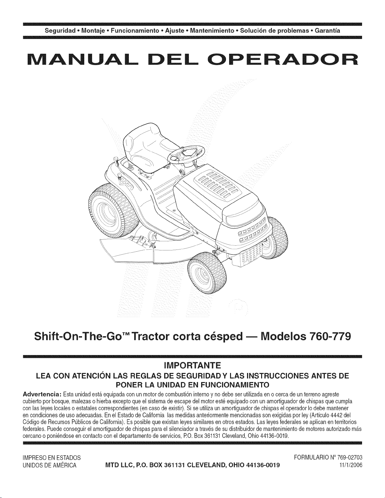
Seguridad • Montaje • Funcionamiento • Ajuste • Mantenimiento • Soluci6n de problemas • Garantia
A AL L P A O
Shift=On=The-Go'" Tractor corta c sped -- Modelos 760-779
IMPORTANTE
LEA CON ATENCION LAS REGLAS DE SEGURIDADY LAS INSTRUCCIONES ANTES DE
PONER LA UNIDAD EN FUNCIONAIVllENTO
Advertencia: Estaunidadest_ equipadacon un motordecornbusti6ninternoy nodebe ser utilizadaen o cercade un terrenoagreste
cubiertoporbosque,rnalezaso hierbaexceptoque el sisternade escapedel motorest_ equipadocon un arnortiguadordechispasque curnpla
con las leyeslocaleso estatalescorrespondientes(en caso de existiO.Sise utilizaunarnortiguadorde chispasel operadorIodebernantener
encondicionesde usoadecuadas.En el EstadodeCalifornia las rnedidasanteriorrnenternencionadassonexigidaspor ley(Articulo4442del
C6digode RecursosPOblicosde California).Es posiblequeexistanleyessirnilaresenotrosestados.Las leyesfederalesse aplicanenterritorios
federales.Puedeconseguirelarnortiguadordechispasparael silenciadora travesde su distribuidorde mantenirnientode rnotoresautorizadorn_s
cercanoo poni_ndoseen contactoconel departarnentode servicios,RO. Box361131Cleveland,Ohio 44136-0019.
IMPRESOEN ESTADOS
UNIDOSDEAME_RICA
MTD LLC, P.O. BOX 361131 CLEVELAND, OHIO 44136-0019
FORMULARIONO769-02703
11/1/2006

Este Manual del Operador es una parte importante de su nuevo tractor corta c_sped.
Lo ayudar_ a montar, preparar y mantener la unidad para obtener los mejores resultados.
Pot favor, lea y comprenda el contenido del manual.
Indice
Indicador de pendiente ...................................... 3
Medidas importantes de seguridad .................. 4
Montaje del tractor corta cesped ...................... 8
Funcionamiento del tractor corta cesped ...... 12
Ajuste su tractor corta cesped ........................ 20
Mantenimiento del tractor corta c_sped ........ 22
AImacenamiento fuera de temporada/
Aditamentos ...................................................... 28
Etiquetas de seguridad .................................... 29
Soluci6n de problemas .................................... 30
Garantia ............................................................. 36
B squecla y registro de n mero de modelo
ANTES DE COMENZAREL MONTAJEDEL EQUIPO NUEVO,
por favor encuentre la placa de modelo del equipo y copb la
informaci6n en la placade modelo de muestra suministrada,
del lado derecho. Puede Iocalizar la placa de modelo mirando
debajo del asbnto.
Esta informaci6nes necesaria para tener acceso al sitio web del
fabricantey/o para obtener asistencia a tra%s del Departamento
de atenci6n al cliente o de un distribuidor de servicios de
mantenimientoautorizado.
f
Model Number
D
www.mtdproducts.com
Serial Number
MTD LLC
P.O. BOX 361131
CLEVELAND, OH 44136
330-220-4683
800-800-731 Oy
Asistencia al Cliente
Pot favor NO devuelva la unidad al minorista a trav_s del cual la compr6 sin antes ponerse en
contacto con Atenci6n a clientes.
En caso de tener problemas para montar este producto o de tener dudas con respecto a los controles, funcionamiento o
mantenimientodel mismo, puede solicitar la ayuda de expertos. Elija entre las opciones que se presentan a continuaci6n:
1. Visite www.mtdproducts.com.
2. Comuniquese por telefono con un representante de asistencia al cliente al 1 (800) 800-7310.
3. El fabdcante del motor es el responsable de todas las cuestiones relacionadascon el rendimiento,la potencia de salida,
las especificaciones,la garantia y el servicio de mantenimiento.Por favor consulte el Manual del propietario/operador del
fabricante del motor, que se entrega pot separado con su unidad.
2
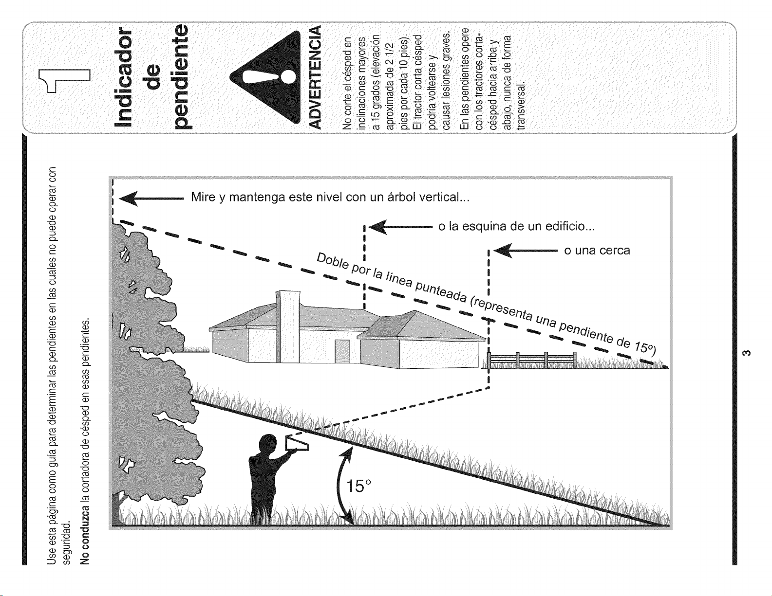
0
(D
(D
0
(D
0
t'--
GO
(D
0
o3
(:D
GO
E
,_
225
O
E
O
O
"r-
225
o5
O9
O.-
O
t'_
O
-'O
e_
O
O
O
N
C
o
O
o
Z
Mire y mantenga este nivel con un arbol vertical...
o la esquina de un edificio...
| _ o una cerca
I
I
I
I
de 15.0
|
15°
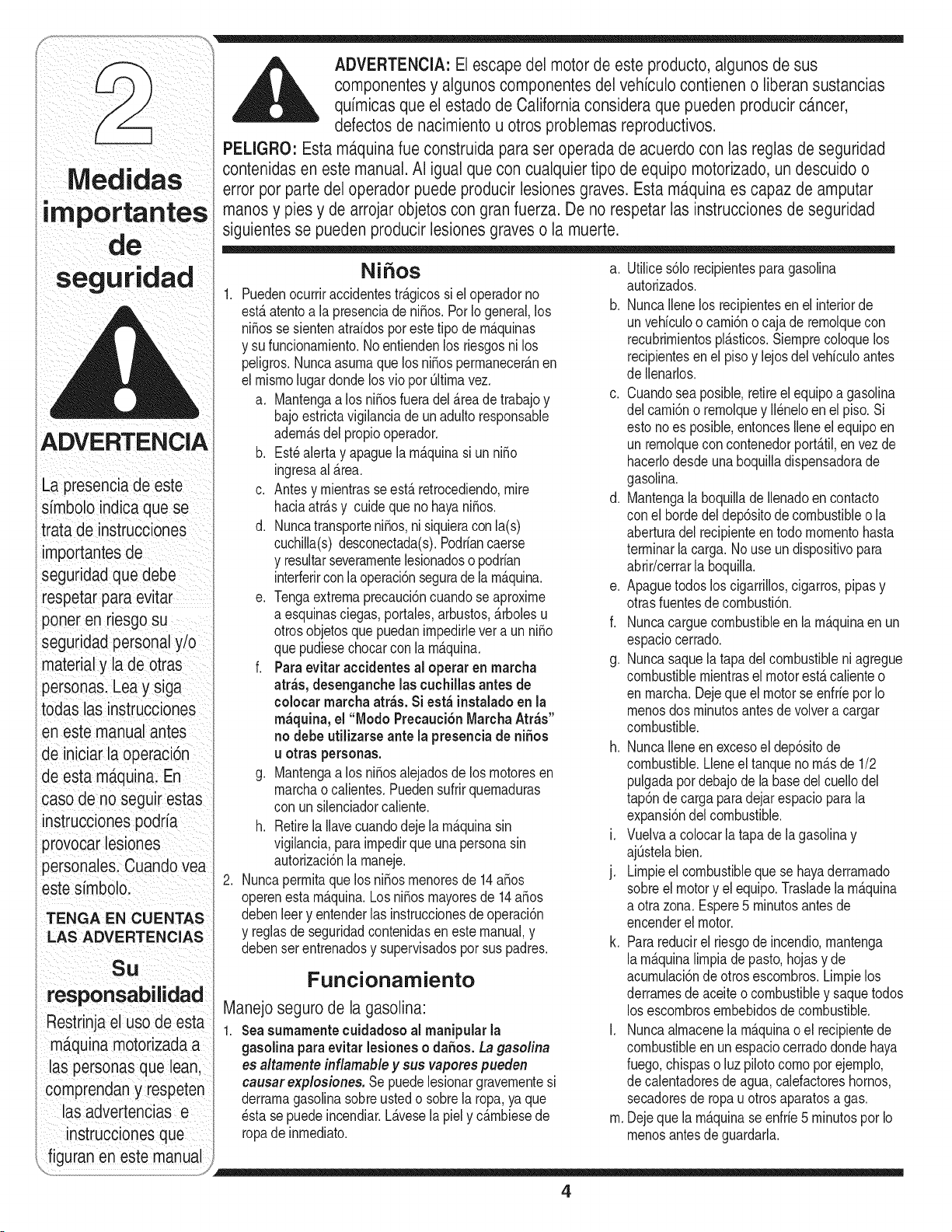
Medidas
ADVERTENCIA
i ¸: /: ::/: ::
La presenciadeeste
s[mbolo indica que se
trata de instrucciones
i
importantes de
seguridad que debe
respetar para ev tar
poner en riesgosu
seguridad personaly!o
materialy la de otras
personasl Lea y siga
todas as instrucciones
en estemanual antes
de iniciar la operac_on
de esta maquina; En
caso deno seguir estas
instrucciones podr[a
provocar lesiones
personalesl Cuandoyea
estesimbolo:
LAS ADVERTENClAS
Su
estrinjaeusodeesta
m_.quinamotorizada
las personasque lean,
comprendany respeten
las advertencias e
l
instrucciones que
ADVERTENClA: El escape del motor de este producto, algunos de sus
componentesy algunos componentes del vehiculo contienen o liberansustancias
quimicas que el estado de Californiaconsidera que pueden producirc_.ncer,
defectos de nacimientou otros problemas reproductivos.
PELIGRO: Esta m_.quinafue construida para set operada de acuerdo con las reglas de seguridad
contenidas en este manual. AI igual que con cualquier tipo de equipo motorizado, un descuido o
error por parte del operador puede producir lesiones graves. Esta maquina es capaz de amputar
manos y pies y de arrojar objetoscon gran fuerza. De no respetar las instrucciones de seguridad
siguientesse pueden producir lesiones graveso la muerte.
NiSos a. utilice s61orecipientesparagasolina
1. Puedenocurriraccidentestr&gicossi el operadorno
est,.atentoa la presenciade ni_os.Por Iogeneral,los
ni_osse sientenatraidosporestetipo dem&quinas
y sufuncionamiento.Noentiendenlos riesgosnilos
peligros.Nuncaasumaquelos ni_ospermanecer_.nen
el mismolugardonde losvio por Oltimavez.
a. Mantengaa los ni5osfueradel &reade trabajoy
bajoestrictavigilanciadeunadulto responsable
adem&sdelpropiooperador.
b. Est_alertay apaguela m_.quinasi un ni_o
ingresaal _.rea.
c. Antesy mientrasse est&retrocediendo,mire
haciaatr&sy cuide quenohayani5os.
d. Nuncatransporteni_os,ni siquieraconla(s)
cuchilla(s)desconectada(s).Podriancaerse
y resultarseveramentelesionadoso podrian
interferirconlaoperaci6nsegurade la m_.quina.
e. Tengaextremaprecauci6ncuandose aproxime
a esquinasdegas, portales,arbustos,_.rbolesu
otrosobjetosquepuedanimpedirlevet a un ni_o
quepudiesechocarconla m_.quina.
f. Para evitar accidentes al operar en rnarcha
atr_s, desenganchelas cuchillasantes de
eolocar mareha atr;_s.Si est;_instaladoen la
m_quina, el "Modo Precauci6nMarchaAtr_s"
no debe utilizarse ante la presenciade niSos
u otras personas.
g. Mantengaa los niSosalejadosde losmotoresen
marchao calientes.Puedensufrirquemaduras
con unsilenciadorcaliente.
h. Retirela Ilavecuandodeje lam_.quinasin
vigilancia,paraimpedirque una personasin
autorizaci6nla maneje.
2. Nuncapermitaque losni5osmenoresde 14a5os
operenestam_.quina.Losni_osmayoresde 14a_os
debenleery entenderlas instruccionesde operaci6n
y reglasde seguridadcontenidasen este manual,y
debenser entrenadosy supervisadospor sus padres.
Funcionamiento
Manejo seguro de la gasolina:
1. Seasurnarnentecuidadosoal rnanipular la
gasolinapara evitarlesioneso dahos. La gasolina
es altamente inflamabley sus vapores pueden
causar explosiones. Sepuede lesionargravementesi
derramagasolinasobreusted o sobrela ropa,ya que
_stase puedeincendiar.L_.vesela piel y c_.mbiesede
ropade inmediato.
autorizados.
b. NuncaIlenelos recipientesen el interiorde
unvehiculoo cami6no cajade remolquecon
recubrimientospl_sticos.Siemprecoloquelos
recipientesenel pisoy lejosdel vehiculoantes
deIlenarlos.
c. Cuandosea posible,retireel equipoa gasolina
delcami6no remolquey II_neloen el piso.Si
estonoes posible,entoncesIleneel equipoen
un remolquecon contenedorport_til,en vezde
hacerlodesdeunaboquilladispensadorade
gasolina.
d. Mantengala boquillade Ilenadoencontacto
conel horde del dep6sitode combustibleo la
aberturadel recipienteen todo momentohasta
terminarlacarga.Nouse undispositivopara
abrir/cerrarla boquilla.
e. Apaguetodoslos cigarrillos,cigarros,pipasy
otrasfuentesdecombusti6n.
f. Nuncacarguecombustibleen la m_.quinaen un
espaciocerrado.
g. Nuncasaquelatapa delcombustibleni agregue
combustiblemientrasel motorest,. calienteo
enmarch& Dejeque el motorse enfrieporIo
menosdos minutosantesdevolvera cargar
combustible.
h. NuncaIleneenexcesoel dep6sitode
combustible.Lleneel tanqueno m_.sde 1/2
pulgadapordebajode la basedel cuellodel
tap6ndecarga paradejarespacioparala
expansi6ndelcombustible.
i. Vuelvaa colocarla tapa de lagasolinay
ajOstelabien.
j. Limpieel combustibleque se hayaderramado
sobreel motory el equipo.Trasladela m_quina
a otrazona. Espere5 minutosantesde
encenderel motor.
k. Para reducirel riesgodeincendio,mantenga
la m_.quinalimpiade pasto,hojasy de
acumulaci6nde otros escombros.Limpielos
derramesdeaceiteocombustibley saquetodos
los escombrosembebidosde combustible.
I. Nuncaalmacenela m_.quinao el recipientede
combustibleenunespaciocerradodondehaya
fuego,chispaso luz pilotocomo por ejemplo,
decalentadoresdeagua,calefactoreshornos,
secadoresde ropa u otros aparatosa gas.
m.Dejequela m_.quinase enfrie5 minutospor Io
menosantesde guardarla.
4
Funcionamientogeneral:
1. Lea,cornprenday respetetodaslas instrucciones
quefiguranen la rn_.quinao en este(os)rnanual(es)
antesdeprocederal ensarnbladoy operaci6ndel
equipo.Guardeestemanualenun lugarseguropara
consultasfuturasy regulates,asi cornoparasolicitar
repuestos.
2. Farniliaricesecon todos loscontrolesy con eluso
adecuadode los misrnos.Sepac6rnodetener
la rn_.quinay c6rnodesconectarloscontroles
r_.pidarnente.
3. Nuncaperrnitaque rnenoresde 14a_osoperenesta
rn_.quina.Losni_osde 14a_os y rnayoresdebenleer
y cornprenderlas instruccionesdeoperaci6ny las
reglasde seguridadcontenidasen estemanual,y
tarnbi_ndebensetcapacitadosy estarsupervisados
por unode los padres.
4. Nuncaperrnitaqueadultossinlos conocirnientos
adecuadosacercade la rn_.quinala operen.
5. Paraayudara evitarel contactocon lascuchillas
o una lesi6npor alg[3nobjetoque seaarrojado,
rnantengaalas personasque Ioobservan,a
los ayudantes,ni_osy rnascotasalejadosal
rnenos25 metrosde la rn_.quinarnientrasest,. en
funcionarniento.Detengalarn_.quinasi alguienentra
en la zona.
6. Reviseminuciosarnentela zonadondese utilizar_.
el equipo.Retiretodaslas piedras,palos,Ilantas,
huesos,juguetesy otrosobjetosextra_osque
podrianset recogidosy arrojadospot la acci6nde
las cuchillas.Losobjetosarrojadosporla rn_.quina
puedenproducirlesionesgraves.
7. Planifiqueel patr6nde corte paraevitar que la
descargadematerialse realicehacialoscarninos,
las veredas,los observadores,etc. Eviteadern_.s
descargarmaterialcontralas paredesy obstrucciones
que podrianprovocarque el materialdescargado
rebotecontrael operador.
8. Paraprotegerselosojos, utilice siernpregalas o
anteojosde seguridadrnientrasopera la rn_.quinao
rnientraslaajustao repara.Losobjetosarrojadosque
rebotanpuedenproducirlesionesocularesgraves.
9. Utilicezapatosde trabajoresistentes,de suelafuerte,
y pantalonesy carnisasajustados.Lasprendas
sueltaso lasalhajaspuedenquedaratrapadasen las
piezasrnovibles.Nuncaopereestarn_.quinaestando
descalzoo con sandalias.
10.Est_atentoa la cortadoray a ladirecci6ndela
descargadelos aditarnentosy no apuntea nadie.
Nuncaoperela cortadorade c_spedsinque est_n
en su lugarapropiadola cubiertade descargao el
colectorde recortesde cesped.
11.Noponga las rnanosni los piescerca de las piezas
rotatoriasni debajode la plataforrnade corte.El
contactocon la(s) cuchilla(s)puedeproducirla
arnputaci6nde rnanosy pies.
12.Unacubiertadedescargaquefalteo est_ da_ada
puedeprovocarlesionesporcontactocon la cuchillao
porobjetosarrojados.
13.Detengala(s) cuchilla(s)cuandocrucesendas
de gravilla,senderoso carninosy cuandono est_
cortandoel c_sped.
14.Est_atentoal tr_.nsitovehicularcuandoest_ operando
cercadeo en crucesde carninos.Estarn_.quinano
debeutilizarseen la via pQblica.
15.No opereestarn_.quinaestandobajo losefectosdel
alcoholo de drogas.
16.Corteel cespedsolarnenteconluz de dia o con una
buenaluz artificial.
17.Nuncatransportepasajeros.
18.Desenganchela(s)cuchilla(s)antesde colocar
rnarchaatr_.s.Retrocedalentarnente.Siernpre
mirehaciaabajoy haciaatr_.santesy rnientrasva
rnarchaatr_.s,paraevitarunaccidente.
19.Reduzcala velocidadantes de dar lavuelta.Opere
la rn_.quinasuavernente.Evitelaoperaci6nerr_.ticay
lavelocidadexcesiva.
20.Desenganchelascuchillas,coloqueel frenode
rnano,detengael motory esperehastaque la(s)
cuchilla(s)se detenga(n)pot cornpletoantes de
retirarelcolectorde recortesdecesped,vaciar
los recortes,desbloquearlatolva,retirarcualquier
residuoo desecho,o realizarcualquierajuste.
21.Nuncadejela rn_.quinaenfuncionarnientosin
vigilancia.Apaguesiernprela(s) cuchilla(s),coloque
latransrnisi6nen neutral,coloqueel freno de rnano,
detengael motory retirela Ilaveantesde bajarsedel
vehiculo.
22.Tengacuidadoal cargaro descargarla rn_.quina
en un rernolqueo carni6n.Esta unidadno debe
conducirseen ascensoo descensode rarnpas,
porquepodrialadearsey provocarlesiones
personalesgraves.La unidadsedebe ernpujar
rnanualrnenteen latampapara cargarlao
descargarlaapropiadarnente.
23.El silenciadory el motor se calientany pueden
producirquernaduras.No lostoque.
24. Reviseelespaciolibreporencirnade la cabeza
antesde conducirbajolas rarnasbajasde _.rboles,
cables,cerrarnientosde puertas,etc. en loscuales
eloperadorpodriaatorarseo serernpujadofuerade
la unidad,Io que podria resultaren lesionesgraves.
25. Desenganchetodos losernbraguesde los
accesorios,presionetotalrnenteel pedaldel frenoy
carnbiea neutralantesdeintentararrancarel motor.
26.Surn_.quinarue dise_adaparacortarcesped
residencialnormal,con unaalturano mayora 10".
No intentecortarcespeddernasiadocrecido,seco
(pot ej.,pastura)ni pilasde hojas secas.El c_sped
y las hojassecaspuedenentrarencontactocon el
escapedelmotory/oacurnularseen la plataforrna
de la cortadorade cesped,convirti_ndoseen un
peligrode incendio.
27.Utilicesolarnenteaccesoriosy aditarnentos
aprobadosparaesta rn_.quinapor el fabricante
original.Lea,cornprenday sigatodas las
instruccionesproporcionadascon los accesorioso
aditarnentosaprobados.
28.Lasestadfsticasindicanque los operadores
rnayoresde 60 a_os seven involucradosen un
alto porcentajede lesionesrelacionadascon
laconducci6ndetractorescortacesped.Estos
operadoresdebenevaluarsucapacidadparaoperar
eltractorcortac_speden forrnasuficienternente
seguraparaprotegersea ellosrnisrnosy a los
dern_.scontralesionesgraves.
29.Si se presentansituacionesque no est_.nprevistas
enestemanual,seacuidadosoy useel sentido
cornQn.P6ngaseencontactocon su representante
deatenci6nal clientepara solicitarasistencia.
Medidas
ADVERTENCIA
La presenciade este
simbolo indica que se
trata de instrucciones
importantesde
seguridad que debe
respetar para evitar
porter en riesgo su
seguridad personal y/o
material y la de otras
personas. Lea y siga
todas las instrucciones
en este manual antes
de iniciar la operaci6n
de esta ma.quina.En
caso de no segu_restas
instruccionespodria
provocar lesiones
persona es. Cuando vea
este simbolo.
TENGA EN CUENTAS
LAS ADVERTENCIAS
SU
responsabilidad
Restrinja el uso de esta
m_tquinamotorizada a
las personasque lean,
comprendany respeten
las advertenc_ase
instruccionesque
figuran en este manual
5
i
segur dad
La presenciade este
i simbolo indica que se
i trata de instrucciones
i importantesde
seguridad que debe
respetar para evitar
i poner en riesgo su
i seguridad personal y/o
materialy la de otras
personas.Lea y siga
todas las instrucc_ones
en este manual antes
de iniciar la operaci6n
de esta m_.quina.En
caso de no seguir estas
instrucciones podria
provocarlesiones
i personales. Cuandovea
i este simbolo.
TENGA EN CUENTAS
LAS ADVERTENCIAS
SU
responsabilidad
Restrinjael uso de esta
m_.quinamotorizada a
las personas que lean,
comprendan y respeten
las advertencias e
instrucciones que
figuran en este manual
Funcionamientoen pendientes:
Las pendientesson un factorirnportantedeperdidade
controlquese relacionaconaccidentesde derrapesy
cafdasque puedenproducirlesionesgravese incluso
la rnuerte.La operaci6nen pendientesrequieremayor
precauci6n.Si nopuederetrocederen la pendienteo
si no se sienteseguro,no realiceningunaoperaci6nde
corte.
Paraseguridad,use el rnedidorde pendientesque
se incluyecornopartede este manualpararnedir
la pendienteantesde operarla unidaden unazona
inclinada.Si la pendientees mayora 15gradosen el
rnedidor,noopereestaunidadenese sector,pues
podriacausarlesionesgraves.
Haga Io siguiente:
1. Cortehaciaarribay abajode laspendientes,no en
forrnatransversal.Tengacuidadocuandocarnbiede
direcci6nal operarla rn&quinaenpendientes.
2. Est_atentoa loshoyos,surcos,baches,rocas,u
otrosobjetosocultos.El terrenodesniveladopuede
voltearla rn_.quina.El cespedalto puedeocultar
obst&culos.
3. Vayaa baja velocidad.ElijaunavelocidadIo
suficienternentebaja,de rnodoqueno tengaque
detenerseo hacercarnbiosrnientrasest,. sobrela
pendiente.Las Ilantaspodrianperdertracci6nsobre
las pendientesaQncuandolos frenosfuncionaran
apropiadarnente.Siernprernantengala rn_.quinaen
carnbiornientrasdesciendelas pendientes,para
poderfrenarcon el motor.
4. Sigalas recornendacionesdel fabricanteparalos
pesoso contrapesosde las ruedas,para rnejorarla
estabilidaddela rn_.quina.
5. Tengaespecialcuidadocon loscolectoresde
cespedu otrosaditarnentos.Los rnisrnospueden
rnodificarla estabilidadde la rn&quina.
6. Hagaquetodoslos movirnientosen laspendientes
seanlentosy graduales.Nocarnbierepentinarnente
la velocidadni ladirecci6n.Un frenadoo carnbiode
velocidadrepentinospuedencausarqueel frentede
la rn_.quinase levantey d_ una volteretahaciaatr_.s,
Io quepodriaproducirlesionesgraves.
7. Evitearrancaro detenerseen unapendiente.Silos
neurn_.ticospierdenlatracci6n,desenganchelas
cuchillasy desciendalentarnentela pendiente.
No haga Io siguiente:
1. No giresobrelas pendientesa rnenosque
seanecesario.Si es posible,gire lentarnentey
gradualrnenteduranteel descenso.
2. No corteel cespedcercadedeclives,zanjaso
terraplenes.Lacortadoradecespedpodria volcarse
repentinarnentesi una de las ruedasestuvierasobre
el hordede unacantilado,zanjao si unhordese
desrnoronara.
3. No intenteestabilizarla rn_.quinaponiendoel pie en el
suelo.
4. No utiliceun colectorde recortesde cespeden
pendientesernpinadas.
5. No corteel cespedhQrnedo.Unarnenortracci6n
podriacausarderrapes.
6. No carnbiea transrnisi6nneutralpara descender.El
excesodevelocidadpodriahacerque el operador
pierdael controlde larn&quina,ocasionandolesiones
gravese inclusola rnuerte.
7. No arrastrecargaspesadasdetr_.sde los accesorios
(porejernplo,carritodebasuracargado,rodillo
decesped,etc.)en pendientesrnayoresde 5
grados.Cuandose desciende,el pesoadicional
tiendea ernpujarel tractory puedehacerque se
pierdael control.(por ejernplo,el tractorpodria
acelerarse,reduciendolacapacidadde frenadoy
rnaniobrabilidad,los accesoriospodrianplegarse
cornoun cortaplurnasy hacerque el tractorse d_
vuelta).
Remolque:
1. RernolqueQnicarnenteutilizandounarn_.quinaque
cuentecon un dispositivode enganchediseSadopara
esafunci6n.No acopleequipo rernolcadoexceptoen
el puntode enganche.
2. Sigalas recornendacionesdel fabricanteen Ioque
respectaa los Ifrnitesde pesode los equiposa
rernolcary al rernolqueen pendientes.
3. Nuncaperrnitala presenciade ni_osuotraspersonas
eno sobrelos equiposrernolcados.
4. Enlas pendientes,el pesodelequiporernolcado
puedecausarp_rdidadetracci6ny perdidade control
dela rn_.quina.
5. Despl_ceselentarnentey dejedistanciaadicionalpara
frenado.
6. No carnbiea transrnisi6nneutralpara descender.
6
Servicio
1. Nuncahagafuncionarunmotoren espacioscerrados
o en unazonacon pocaventilaci6n.Elescapedel
motorcontienernon6xidode carbono,un gasinodoro
y letal.
2. Antesde lirnpiar,repararo inspeccionarlarn_.quina,
cornpruebeque la(s) cuchilla(s)y todaslaspiezas
rn6vilesse hayandetenido.Desconecteel cablede
la bujfay p6ngalode rnaneraquehagarnasacontra
el motorpara evitarque se enciendadernanera
accidental.
3. Reviseperi6dicarnente,paraasegurarsede que las
cuchillassedetenganpor cornpletoen unespaciode
aproxirnadarnentecinco(5) segundosdespu_sde
accionarel controlde desenganche.Si las cuchillas
no se detienendentrode este periodode tiernpo,
su unidaddeber_,ser reparadapor un distribuidor
autorizadoMTD.
4. Reviseconfrecuenciael funcionarnientodel sisterna
de frenos,ya que est,. sujetoa desgasteporla
operaci6nnormal.Ajustey efectQernantenirniento
segQnse requiera.
5. Inspeccionelos pernosde rnontajedela(s) cuchilla(s)
y delmotora intervalosfrecuentes,para verificar
queest_nbienajustados.Adern_.s,inspeccione
visualrnentela(s) cuchilla(s)en buscade daSos(pot
ejernplo,desgasteexcesivo,abolladuras,rajaduras,
etc.). Reernplacela(s) cuchilla(s)s61ocon piezasde
los fabricantesdeequiposoriginalesenurneradasen
estemanual."La utilizaci6nde piezasquenocurnplen
con las especificacionesde equiposoriginalespodria
tenetcornoresultadoun rendirnientoincorrectoy
adern_.sponeren riesgola seguridad."
6. Lascuchillasde las cortadorasde cespedsonfilosas.
Envuelvala cuchillao utiliceguantesy extremelas
precaucionescuandoefectQernantenirniento.
7. Mantengatodas las tuercas,pernosy tornillosbien
ajustadosparaasegurarsede que la rn_.quinase
encuentraen condicionessegurasde operaci6n.
8. Nuncaintentealterarel sisternadebloqueode
seguridadu otros rnecanisrnosde seguridad.Controle
peri6dicarnentequefuncionende forrnaadecuada.
9. Despu_sde golpearcontraalg[3nobjetoextraSo,
detengael motor,desconecteel(los) cable(s)
de bujia y conecteel motora rnasa.Inspeccione
rninuciosarnentepara versi la rn_.quinaest,.daSada.
Repareel daSoantesde arrancary operar.
10.Nuncatratedehacerajusteso reparacionesa la
rn_.quinarnientrasel motorest,.enrnarcha.
11.Loscornponentesdelcolectorde recortesdecesped
y la cubiertade descargaest_.nsujetosa desgaste
y daSosquepodriandejarexpuestaspiezasque
se rnueveno perrnitirque se arrojenobjetos.Para
protegersu seguridad,verifiquefrecuenternente
todosloscornponentesy reernpl_.celoss61ocon
piezasde losfabricantesde equiposoriginales
enurneradaseneste manual."La utilizaci6nde
piezasquenocurnplencon lasespecificacionesde
equiposoriginalespodria tenercornoresultadoun
rendirnientoincorrectoy adern_.sponeren riesgola
seguridad."
12.No carnbiela configuraci6ndel reguladordel motor
ni Ioopere a unavelocidaddernasiadoelevada.El
reguladorcontrolala velocidadrn_.xirnasegurade
operaci6ndel motor.
13.Mantengao reernplacelasetiquetasde seguridade
instruccionessegQnseanecesario.
14.Respetelas leyesy reglarnentacionesreferentesa
laelirninaci6ncorrectade combustible,aceite,etc.
paraprotegerel rnedioarnbiente.
i mp0rta rites
La presenciade este
simbolo indica que se
trata de instrucciones
importantes de
seguridadque debe
respetar para evitar
poner en riesgo su
seguridadpersonal y/o
material y la de otras
personas. Lea y siga
todas las instrucciones
en este manual antes
de iniciar la operaci6n
de esta m_.quina.En
;aso de no seguir estas
instrucciones podrfa
provocar lesiones
personales. Cuando vea
este sfmbolo.
TENGA EN CUENTAS
LAS ADVERTENCIAS
SLI
responsabilidad
Restrinja el uso de esta
maqu_namotorizadaa
las personasque lean.
comprendan y respeten
las advertencias e
instrucciones que
figuran en este manual
7
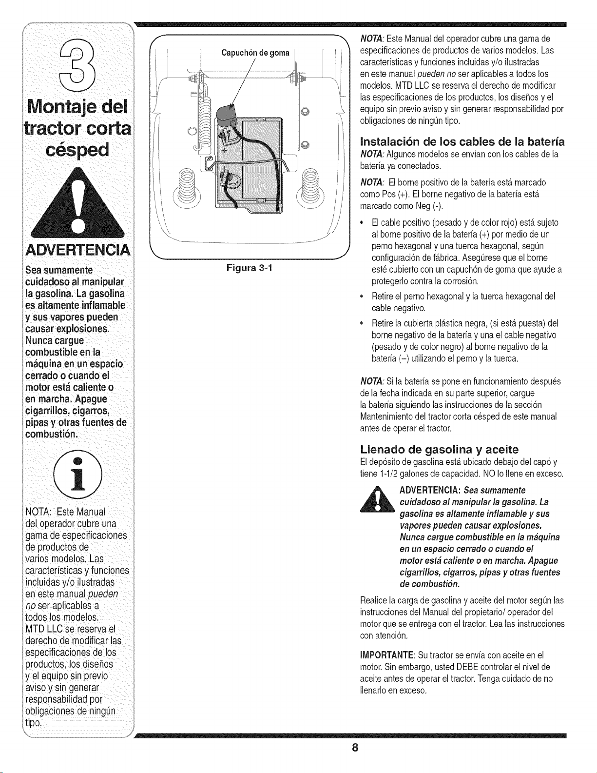
ADVERTENCIA
cuidadoso al manipular
lagasolina, Lagas01ina
es altamente inflamable
y sus Vaporespueden
ca,,sareXp os o,,es:
Nunca cargue
combustible en la
m_quina enun espacio
Cerrado o Cuando el
motor est_ caliente o
en marcha: Apague
cigarrillos, cigarrosi
pipas y otras fuentes de
combusti6.i
NOTA Este Manua
del operador cubre una
gama de especificaciones
ae productoS de
varios modelosl Las
caracteristicas y funciones
incluidas yio ilustradas
en este manual pueden
no ser aplicables a
todos los modelos:
MTD LLC se reserva el
derecho de modificar !as
especificaciones de los
productos, los dBenos
y el equipo sin previo
a.visoy Sin
responsabilidad pot
Capuch6n de goma
Figura 3=1
NOTA:EsteManualdel operadorcubreuna gamade
especificacionesde productosde variosmodelos.Las
caracteristicasy funcionesincluidasy/o ilustradas
enestemanualpuedennoser aplicablesa todos los
modelos.MTDLLCse reservael derechodemodificar
las especificacionesde los productos,losdise_osy el
equiposin previoavisoy singenerarresponsabilidadpor
obligacionesde ningOntipo.
Instalaci6n de los cables de la bateria
NOTA:Algunosmodelosse enviancon los cablesde la
bateriaya conectados.
NOTA: Elbornepositivodela bateriaest& marcado
comoPos(+). Elbornenegativode la bateriaest,.
marcadocomoNeg (-).
• El cable positivo(pesadoy de color rojo)est& sujeto
al bornepositivode la bateria(+) por mediode un
pernohexagonaly una tuercahexagonal,seg[3n
configuraci6nde f_.brica.AsegQreseque el borne
est_cubiertoconun capuch6nde gomaqueayudea
protegerlocontralacorrosi6n.
• Retireel pernohexagonaly la tuerca hexagonaldel
cablenegativo.
• Retirela cubiertapl_.sticanegra,(si est,.puesta)del
bornenegativode la bateriay una el cablenegativo
(pesadoy decolornegro) al borne negativode la
bateria(-) utilizandoel pernoy latuerca.
NOTA:Si la bateriase poneenfuncionamientodespu_s
dela fecha indicadaen su parte superior,cargue
la bateriasiguiendolas instruccionesde la secci6n
Mantenimientodeltractorcortacespedde este manual
antesde operarel tractor.
Llenado de gasolina y aceite
Eldep6sitodegasolinaest&ubicadodebajodel cap6 y
tiene 1-1/2galonesdecapacidad.NO IoIleneen exceso.
,_ ADVERTENCIA:Seasumamente
cuidadoso al manipular la gasolina. La
gasolina es altamente inflamable y sus
vaporespueden causar explosiones.
Nunca cargue combustible en la mbquina
en un espacio cerrado o cuando el
motor estb caliente o en marcha. Apague
cigarrillos, cigarros, pipas y otras fuentes
de combusti6n.
Realicelacargade gasolinay aceite del motor segQnlas
instruccionesdelManualdel propietario/operadordel
motorquese entregacon el tractor.Lealas instrucciones
conatenci6n.
IMPORTANTE:Sutractor seenviacon aceiteen el
motor.Sinembargo,ustedDEBEcontrolarel nivelde
aceiteantesde operarel tractor.Tengacuidadode no
Ilenarloenexceso.
8
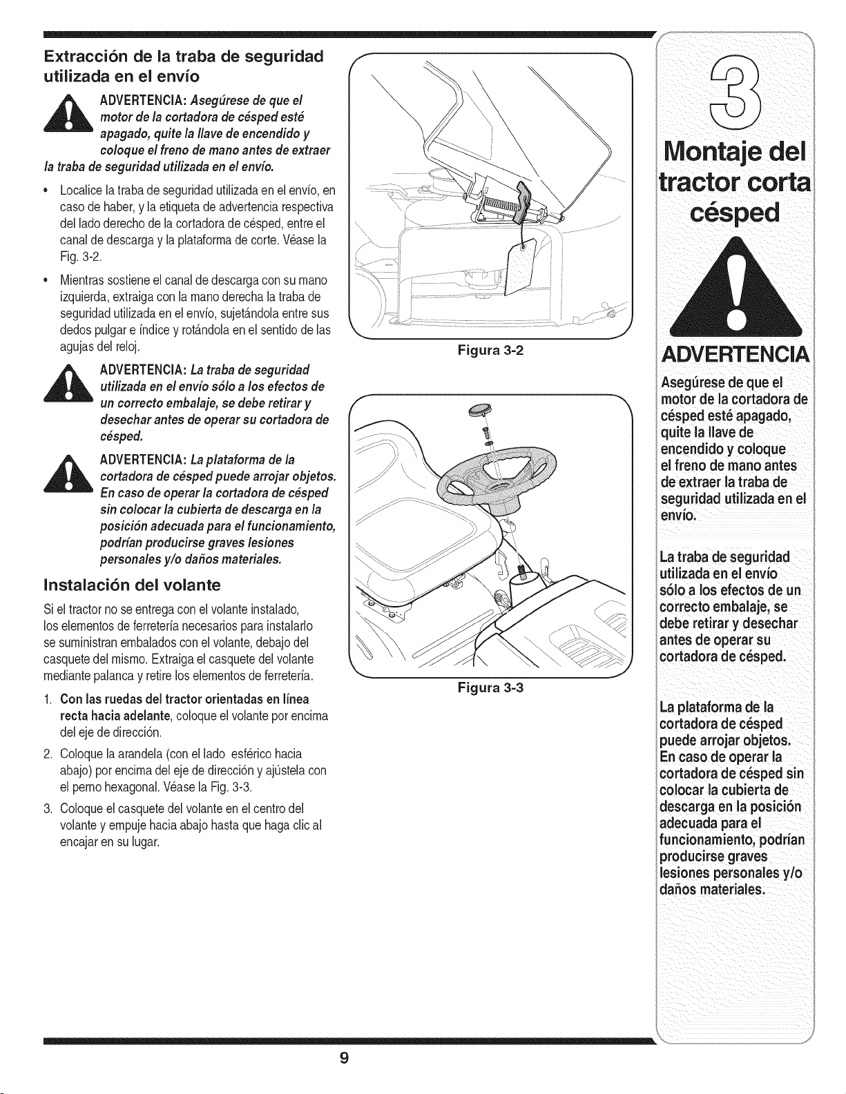
E×tracci6n de la traba de seguridad
utilizada en el envio
,_ ADVERTENClA:Aseg(_resede que el
motor de la cortadora de c_sped est_
apagado, quite la Ilavede encendido y
coloque el freno de mano antes de extraer
la traba de seguridad utilizada en el env(o.
Localicela trabade seguridadutilizadaenel envio,en
casode haber,y la etiquetadeadvertenciarespectiva
del ladoderechode lacortadorade cesped,entreel
canalde descargay la plataformadecorte.Wase la
Fig.3-2.
Mientrassostieneel canalde descargacon su mano
izquierda,extraigacon la manoderechala trabade
seguridadutilizadaen el envio,sujetandolaentresus
dedospulgare indicey rot_ndolaen el sentidode las
agujasdel reloj.
ADVERTENCIA:Latraba de seguridad
utilizada en el envio s61oa los efectos de
un correcto embalaje, se deberetirar y
desechar antes de operar su cortadora de
c_sped.
ADVERTENCIA:Laplataforma de la
cortadora de c_spedpuede arrojar objetos.
En caso de operar la cortadora de c_sped
sin colocar la cubierta de descarga en la
posici6n adecuada para el funcionamiento,
podrian producirse graves lesiones
personales y/o da_os materiales.
Instalaci6n del volante
Si el tractornose entregacon elvolanteinstalado,
los elementosde ferreterianecesariospara instalarlo
se suministranembaladosconel volante,debajodel
casquetedel mismo.Extraigael casquetedel volante
mediantepalancay retirelos elementosde ferreteria.
1. Con las ruedas del tractor orientadas en linea
recta hacia adelante, coloqueel volanteporencima
del eje de direcci6n.
2. Coloquelaarandela(conel lado esf_ricohacia
abajo)porencimadelejede direcci6ny ajOstelacon
el perno hexagonal.Wase la Fig. 3-3.
3. Coloqueelcasquetedelvolanteenel centrodel
volantey empujehaciaabajohastaquehagaclical
encajarensu lugar.
Figura 3=2
Figura 3=3
9
Montaje del
tractor corta
ADVERTENCIA
Aseg=Jresedeque el
motor de la cortadora de
o spedest apagado,
quite la Ilave de
encendido y coloque
el freno de rnano antes
de extraer la traba de
seguridad utilizada en el
envio:
La traba de seguridad
utilizada en el envio
s61o a los efectos de un
correcto ernbalaje, se
debe retirar y desechar
antes de operar su
cortadora de cesped.
La plataforrna de la
cortadora de eesped
puede arrojar objetos.
En caso de operar la
cortadora de cesped sin
colocar la cubierta de
descarga en la posici6n
adecuacla para el
funcionarniento, podnan
producirse graves
lesiones personales y/o
daSos rnateriales.
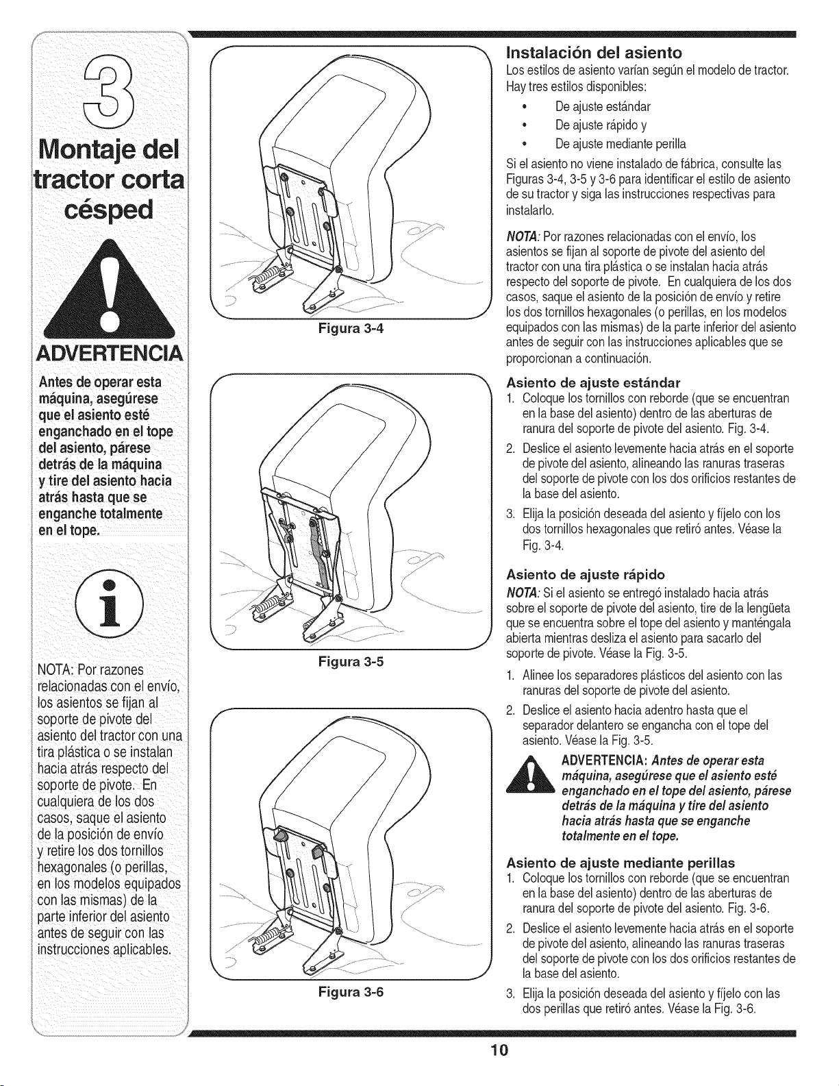
Instalaci6n del asiento
ADVERTENCIA
A.tesdeope,a,e.ta
rn_quina, aseg_rese
que el asiento est_
enganchado enei tope
del asiento, p_rese
detr_s de la rn_quina
y tire del asiento hacia
atras hasta quese
enganche totalrnente
enel tope:
NOTA: Por razones
relacionadas con el enVio,
los asientos se fijan al
soporte de pivote del
asiento del iract0r con una
tira pl_tst!cao se instalan
hacia atra.srespecto del
soporte de pivote: En
cualquiera delos dos
cas0s, Saqueelasiento
de la posici6n de envio
y retire los dos tornillos
hexagonales(o periHas;
en losmodelos equipados
con las mismas)dela
parte inferior del asiento
antes de Seguircon las
instrucciones ap icable&
Figura 3-4
Figura 3-5
Figura 3-6
Losestilosde asientovarian segOnel modelode tractor.
Haytres estilosdisponibles:
• De ajusteest_.ndar
De ajuster_.pidoy
• De ajustemedianteperilla
Siel asientono viene instaladode f_.brica,consultelas
Figuras3-4,3-5 y 3-6 paraidentificarelestilode asiento
desu tractory sigalas instruccionesrespectivaspara
instalarlo.
NOTA:Porrazonesrelacionadasconel envio, los
asientosse fijanal soportede pivotedelasientodel
tractorconunatira pl_.sticao se instalanhaciaatr_.s
respectodelsoportede pivote. En cualquierade los dos
casos,saqueelasientode la posici6nde envioy retire
los dostornilloshexagonales(o perillas,en los rnodelos
equipadoscon las mismas)de la parteinferiordel asiento
antesde seguircon las instruccionesaplicablesque se
proporcionana continuaci6n.
Asiento de ajuste est_ndar
1. Coloquelos tornilloscon reborde(quese encuentran
enla basedel asiento)dentrode lasaberturasde
ranuradelsoportede pivotedel asiento.Fig.3-4.
2. Desliceel asientolevementehaciaatr_.sen el soporte
depivotedel asiento,alineandolas ranurastraseras
delsoportede pivotecon losdos orificiosrestantesde
la basedel asiento.
.
Elijala posici6ndeseadadel asientoy fijelocon los
dostornilloshexagonalesque retir6antes.Wase la
Fig.3-4.
Asiento de ajuste r_pido
NOTA:Siel asientose entreg6instaladohaciaatr_.s
sobreel soportede pivotedel asiento,tire de la leng_Jeta
quese encuentrasobreel topedel asientoy mant_ngala
abiertamientrasdeslizael asientoparasacarlodel
soportede pivote.Wase la Fig. 3-5.
1. Alineelos separadorespl_.sticosdelasientocon las
ranurasdel soportede pivotedel asiento.
2. Desliceel asientohaciaadentrohastaqueel
separadordelanterose enganchaconel topedel
asiento.Wase la Fig.3-5.
_ DVERTENCIA:Antes de operar esta
m#quina, aseg#rese que e! asiento est#
enganchado en el tope del asiento, p#rese
detr#s de la m#quina y tire del asiento
hacia arras hasta quese enganche
totalmente en el tope.
Asiento de ajuste mediante perillas
1. Coloquelos tornilloscon reborde(quese encuentran
enla basedel asiento)dentrode lasaberturasde
ranuradelsoportede pivotedel asiento.Fig.3-6.
2. Desliceel asientolevementehaciaatr_.sen el soporte
depivotedel asiento,alineandolas ranurastraseras
delsoportede pivotecon losdos orificiosrestantesde
la basedel asiento.
3. Elijala posici6ndeseadadel asientoy fijelocon las
dos perillasque retir6antes.Wase la Fig.3-6.
10
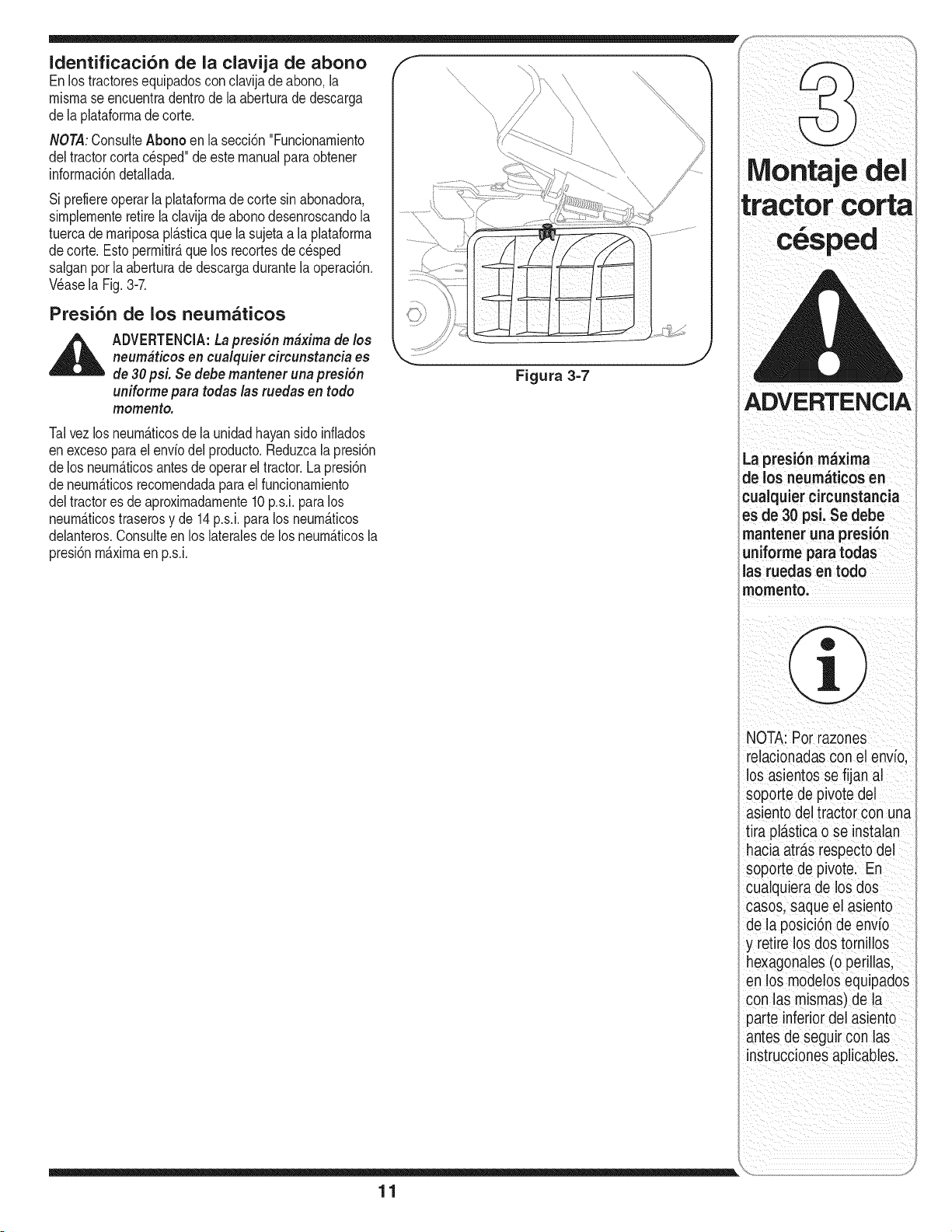
/- _,
Identificaci6n de la clavija de abono .....
Enlostractoresequipadoscon clavijade abono,la ....
mismase encuentradentrodela aberturade descarga ".. .............. \
de la plataformade corte. '........
/
:::_ b I
NOTA:Consulte Abono en la seccidn "Funcionamiento ....' ,
Si prefiereoperarla plataformade cortesinabonadora, L,u!,_,L,_.#,{lff_l_{'_" _.w,_.#=Luit'_llff{_
sirnplementeretirelaclavijade abonodesenroscandola
tuercademariposapl_.sticaquela sujetaa la plataforma
de corte.Esto permitir_,quelos recortesde cesped
salganpot la aberturade descargadurantela operaci6n.
Wase la Fig.3-7.
Presi6n de los neum_ticos
_ ADVERTENCIA:LapresiSn m#xima de los
neum#ticos en cualquier circunstancia es
de 30 psL Se debemantener unapresiSn Figura 3=7
uniforme para todas las ruedas en todo
momento.
Talvez losneum_.ticosdela unidadhayansidoinfiados
en excesopara el enviodel producto.Reduzcala presi6n La presi6n maxima
de los neum_.ticosantesde operarel tractor.Lapresi6n de los neumaticos en
de neurn_.ticosrecomendadaparael funcionarniento cualquier circunstancia
del tractores de aproximadarnente10p.s.i, paralos
neum_.ticostraserosy de 14p.s.i,paralos neum_.ticos es de 30 psi, Se debe
delanteros.Consulteen loslateralesde losneum_.ticosla mantener una presi6n
presi6nm_.ximaen p.s.i, uniforrne para todas
las ruedas en todo
momento,
NOTA: P0r razones
relaci0nadaScon el envio,
10Sasientos se fijan al
soporte de piv0te del
asiento del tractor con una
tira pla.sticao Se instalan
hacia atra.srespecto del
soporte de pivotel En
cualquiera de los dos
casos, saque el asiento
dela posici6n de envio
y retire 10sdos torn!llos
hexag0nales (o perilla&
en los mode!os equipados
con las mismas)de la
parte inferior del asiento
antes de Seguirc0n las
instrucciones aplicables.
\
11
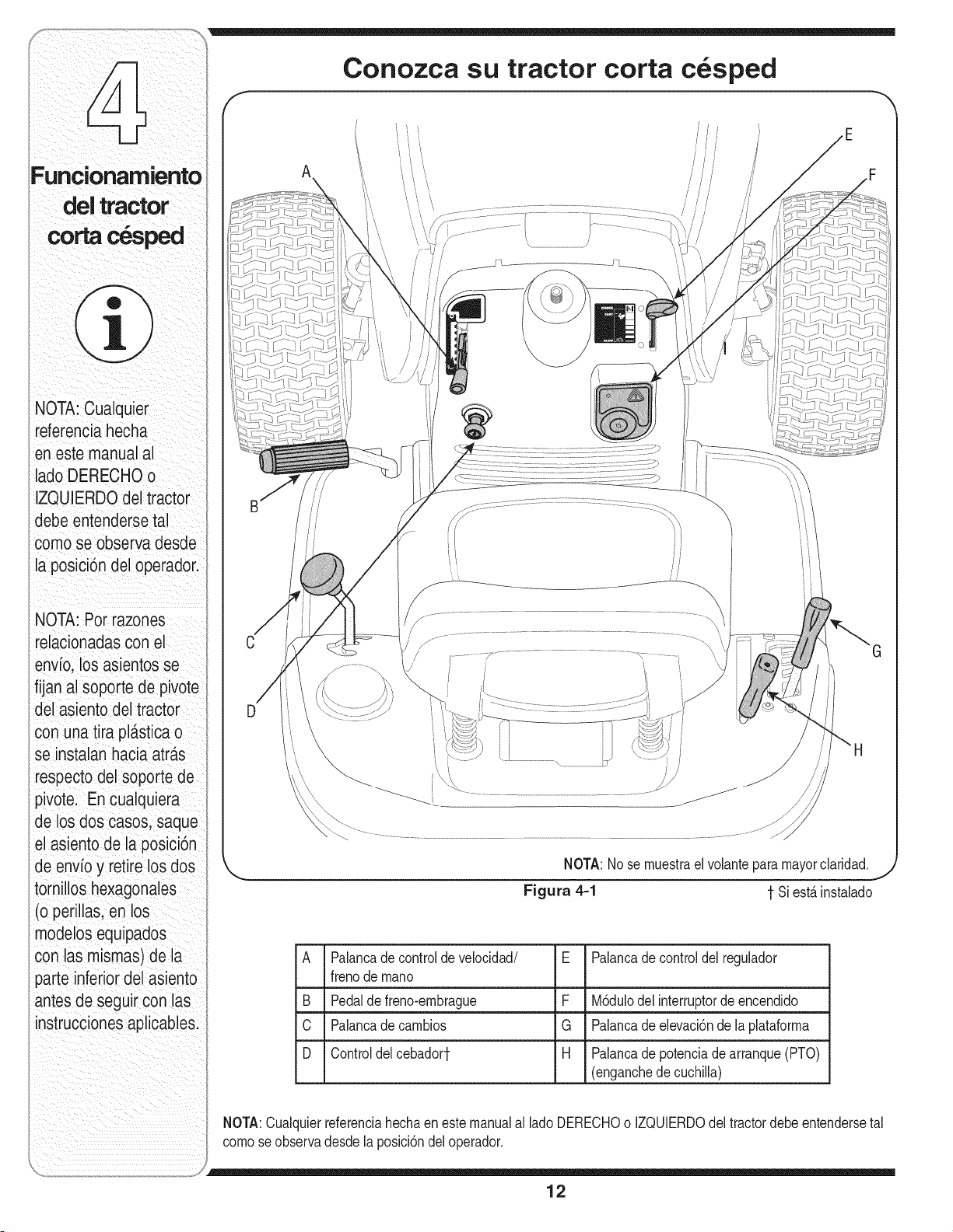
Conozca su tractor corta c sped
NOTA: Cualquier
referencia hecha
en este manual al
ladoDERECHOo
IZQUIERDOdel tractor
debe entendersetal
como se observa desde
la posici6n del operador.
NOTA: Por razones
relacionadascon el
envb, los asientosse
fijan al soporte de pivote
del asiento del tractor
con una tira pl_.sticao
se instalan haciaatr£s
respecto del soporte de
pivote. En cualquiera
de los dos casos, saque
el asiento de la pos_c_on
de envio y retire los dos
tornillos hexagonales
(o perillas, en los
modelos equipados
con las mismas) de la
parte inferior del asiento
antes de seguir con las
instrucciones aplicables.
A
/
NOTA:Nose muestrael volantepara
Figura 4-1 1 Si est,.instalado
A
B
C
D
Palancade controlde velocidad/
frenode mano
Pedalde freno-embrague
Palancade cambios
Controldelcebadort
E Palancade controldel regulador
F M6dulodel interruptorde encendido
G Palancade elevaci6nde laplataforma
H Palancadepotenciadearranque(PTO)
(enganchede cuchilla)
NOTA:Cualquierreferenciahechaen este manualal ladoDERECHOo IZQUIERDOdel tractordebeentendersetal
comoseobservadesdela poslci6ndel operador.
12
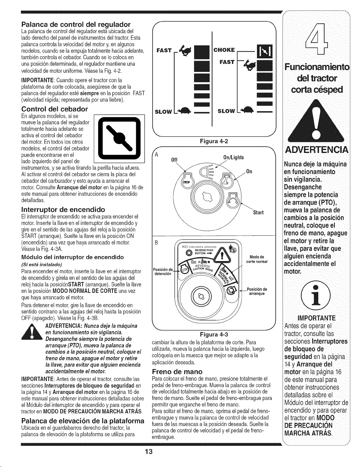
m
Palanca de control del regulador
Lapalancade controldel reguladorest,.ubicadadel
ladoderechodel panelde instrurnentosdeltractor.Esta
palancacontrolala velocidaddel motory,en algunos
rnodelos,cuandosela ernpujatotalrnentehaciaadelante,
tarnbi_ncontrolael cebador.Cuandose Iocolocaen
unaposici6ndeterrninada,el reguladorrnantieneuna
velocidadde motoruniforrne.Wase la Fig.4-2.
IMPORTANTE:Cuandoopere el tractorcon la
plataforrnade cortecolocada,aseg@esede que la
palancadel reguladorest_siempre enla posici6n FAST
(velocidadr@ida; representadapor una liebre).
Control del cebador
Enalgunosrnodelos,si se
rnuevela palancadel regulador
totalrnentehaciaadelantese
activaelcontroldelcebador
delmotor.Entodoslos otros
rnodelos,elcontroldelcebador
puedeencontrarseen el
ladoizquierdodel panelde
instrumentos,y se activatirandolaperillahaciaafuera.
AIactivarel controldel cebadorsecierra laplacadel
cebadordelcarburadory esto ayudaa arrancarel
motor.ConsulteArranquedel motor en lap_.gina16de
estemanualparaobtenerinstruccionesde encendido
detalladas.
FAST
f
SLOW
Interruptor de encendido
El interruptordeencendidoseactivaparaencenderel
motor.InsertelaIlaveen el interruptorde encendidoy
gireenel sentidode Insagujasdel reloja la posici6n
START(arranque).Sueltela Ilaveen la posici6nON
(encendido)unavezquehayaarrancadoel motor.
Wase la Fig.4-3A.
M6dulo del interruptor de encendido
(Si est# instalado)
Paraencenderel motor,insertela Ilaveen el interruptor
deencendidoy girelaenel sentidode las agujasdel
relojhaciala posici6nSTART(arranque).Sueltela Ilave
en la posici6nMODONORMALDE CORTEunavez
quehayaarrancadoel motor.
Paradetenerel motor,gire la Ilavede encendidoen
sentidocontrarioalas agujasdelrelojhastalaposici6n
OFF(apagado).Wase la Fig.4-3B.
_ DVERTENClA:Nunca deje la m#quina
en funcionamiento sin vigilancia.
Desenganchesiempre la potencia de
arranque(PTO),mueva la palanca de
cambios a la posiciSn neutral, co/oque el
freno de mano, apague el motor y retire
la Ilave,para evitar que alguien encienda
accidentalmente el motor.
IMPORTANTE:Antesdeoperarel tractor,consulteIns
seccionesInterruptores de bloqueo de seguridad en
la p&gina14y Arranque del motor en lap&gina16de
estemanualparaobtenerinstruccionesdetalladassobre
el M6dulodel interruptorde encen.didoy paraoperar el
tractoren MODO DEPRECAUClONMARCHAATRAS.
Palanca de elevaci6n de la plataforma
Ubicadaenel guardabarrosderechodel tractor,la
palancadeelevaci6ndela plataforrnase utiliza para
e,m
|1
CHOKE
FAST
SLOW
ms
Rmm
Off
Figura 4-2
On/Lights
Start
@
©
Modo de
torte normal
PosicJ6n de
arranque
Figura 4=3
carnbiarla alturade la plataforrnade corte.Para
utilizarla,rnuevala palancahaciala izquierda,luego
col6quelaen la rnuescaque rnejorseadaptea la
aplicaci6ndeseada.
Freno de mano
Paracolocarelfreno de rnano,presionetotalrnenteel
pedaldefreno-ernbrague.Muevalapalancadecontrol
de velocidadtotalrnentehaciaabajoen la posici6nde
frenode rnano.Suelteel pedal de freno-ernbraguepara
perrnitirqueengancheel frenode rnano.
Parasoltarel frenode rnano,oprirnael pedalde freno-
ernbraguey rnuevala palancadecontrolde velocidad
fuerade las rnuescasa la posici6ndeseada.Sueltela
palancade controlde velocidady el pedaldefreno-
ernbrague.
13
ADVERTENCIA
Nunoa deje la m_quina
en funcionamiento
sin vigilancia.
siempre la potencia
de arranque (PTO)
mueva la palanca de
cambios a la posici6n
neutral, coloque
freno de mano, apag ue
el motor y retire la
Ilave; para evitar que
alguien encienda
accidentalmente el
motorl
llV]PORTANTE
Antes de opeiar el
:ractor,consulte las
secciones lnterruptores
de bloqueo de
seguridad en la p_.gina
14.y Arranq ue del
motor en la p_tgina16
de este manual para
obtener instrucciones
detalladassobre el
M6dulo del interruptorde
encendido y para operar
el tractor en MODO
DE PRECAUCI_N
_ARCHA ATRAS.
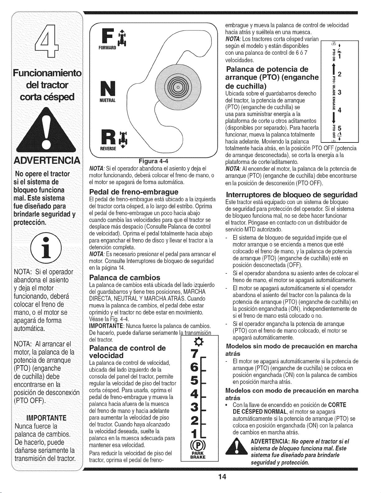
ernbraguey rnuevalapalancade controlde velocldad
/A _ _ haciaatrfisy su61telaenunarnuesca.
//I J r ,T, NOTA:Lostractorescortacespedvarian __
( z_J L.] FORWARD_ seg_nelrnodeloyestfindisponibles &*
con una pa ancadecontro de6d7 _2
o |
velocldades. =
Funcionamiento Palanca de potencia de ! 2
!
ADVERTENq
Noopor trBoto,
si el sistema de
bJoqueo funciona
real, Este sisterna
fue disehado para
brindarle seguridad y
protecci6ni
NOTA: Si el operador
abandona el asiento
y deja el motor
funcionando,debera
colocar el freno de
mano, o el motorse
apagara de forma
autom_ttica.
NOTA: AI arrancar el
motor, la palanca de la
potenciade arranque
(PTO) (enganche
de cuchilla) debe
encontrarse en la
posici6n de desconexbn
(PTO OFF).
IMPORTANTE
Nuncafuerce la
palancade cambios.
De hacerlo, puede
daSarseseriamente la
transmis_6ndel tractor.
NUETRAL
REVERSE_
Figura 4-4
NOTA:Si el operadorabandonael asientoy deja el
motorfuncionando,deber_,colocarel frenodernano,o
el motorse apagar_,de forrnaautorn_.tica.
Pedal de freno-embrague
Elpedaldefreno-ernbragueest,.ubicadoa la izquierda
deltractorcortacesped,a Io largodel estribo.Oprirna
el pedalde freno-ernbragueun pocohaciaabajo
cuandocarnbialasvelocidadespara que el tractorse
desplacern_.sdespacio(ConsultePalancade control
develocidad).Oprirnaelpedaltotalrnentehaciaabajo
paraengancharel frenode disco y Ilevarel tractora la
detenci6ncornpleta.
NOTA:Es necesariopresionarel pedalparaarrancarel
motor.ConsulteInterruptoresde bloqueode seguridad
en la p_.gina14.
Palanca de cambios
La palancade carnbiosest&ubicadadel lado izquierdo
delguardabarrosy tienetres posiciones,MARCHA
DIRECTA,NEUTRALY MARCHAATRAS.Cuando
rnuevala palancadecarnbios,elpedaldebeestar
oprirnidoy el tractorno debe estaren rnovirniento.
Wase la Fig.4-4.
IMPORTANTE:Nuncafuercela palancade carnbios.
De hacerlo,puededaSarseseriarnentelatransrnisi6n
deltractor. 0
Palanca de control de
velocidad
La palancade controlde velocidad,
ubicadadel lado izquierdode la
consoladelpaneldeltractor,perrnite
regularla velocidadde piso del tractor
cortac_sped.Parausarla,oprirnael
pedalde freno-ernbraguey rnuevala
palancahaciaafuerade la rnuesca
delfrenode rnanoy haciaadelante
paraaurnentarlavelocidaddepiso
deltractor.Cuandohayaalcanzado =
lavelocidaddeseada,sueltela
palancaen la rnuescaadecuadapara ,,,_'
rnanteneresavelocidad.
Parareducirla velocidadde pisodel PARK
tractor,oprirnael pedalde freno- BRAKE
arranque (PTO) (enganche
de cuchilla)
Ubicadasobreelguardabarrosderecho
deltractor,la potenciade arranque
(PTO)(enganchede cuchilla)se
usa parasurninistrarenergiaa la
plataforrnadecorte u otros aditarnentos
(disponiblesporseparado).Parahacerla
funcionar,rnuevala palancatotalrnente
haciaadelante.Moviendola palanca
o
_3
m
_4
!
"8
,t5
totalrnentehaciaatr_.s,enla posici6nPTOOFF(potencia
dearranquedesconectada),se corta la energiaa la
plataforrnadecorte/aditarnento.
NOTA:AIencenderel motor,la palancade la potenciade
arranque(PTO)(enganchede cuchilla)debeencontrarse
enla posici6nde desconexi6n(PTOOFF).
Interruptores de bloqueo de seguridad
Estetractorest,.equipadoconun sisternade bloqueo
deseguridadparaprotecci6ndel operador.Si el sisterna
debloqueofuncionarnal,nose debe hacerfuncionar
el tractor.P6ngaseen contactocon un distribuidorde
servicioMTDautorizado.
El sisternade bloqueode seguridadirnpideque el
motorarranqueo se enciendaa rnenosque est_
colocadoel frenode rnano,y la palancade potencia
dearranque(PTO)(enganchede cuchilla)est_ en
posici6ndesconectada(OFF).
Siel operadorabandonasu asientoantes de colocarel
frenode rnano,el motorse apagar_,autom_.ticarnente.
El motorse apagar_,autorn_.ticarnentesi el operador
abandonael asientodel tractorconla palancade la
potenciade arranque(PTO) (enganchede cuchilla)en
la posici6nenganchada(ON), independienternentede
si el frenode rnanoest,.colocadoo no.
Siel operadorenganchala potenciade arranque
(PTO)conel frenode rnanocolocado,el motor se
apagar_,autorn_.ticarnente.
ModeJos sin modo de precauci6n en marcha
atr_s
El motorse apagar_,autorn_.ticarnentesi la potenciade
arranque(PTO)(enganchede cuchilla) secoloca en
posici6nenganchada(ON)con la palancade carnbios
enposici6nrnarchaatr_.s.
Modelos con modo de precauci6n en marcha
atr_s
• Conla Ilavede encendidoen posici6nde CORTE
DE CESPEDNORMAL,el motorse apagar&
autornAticarnentesi lapotenciadearranque(PTO)se
colocaen posici6nenganchada(ON)con la palanca
decarnbiosenrnarchaatr&s.
_ DVERTENCJA:No opere el tractor si elsistema de bloqueo funciona real Este
sistema rue disefado para brindarle
seguridad y proteccidn.
14
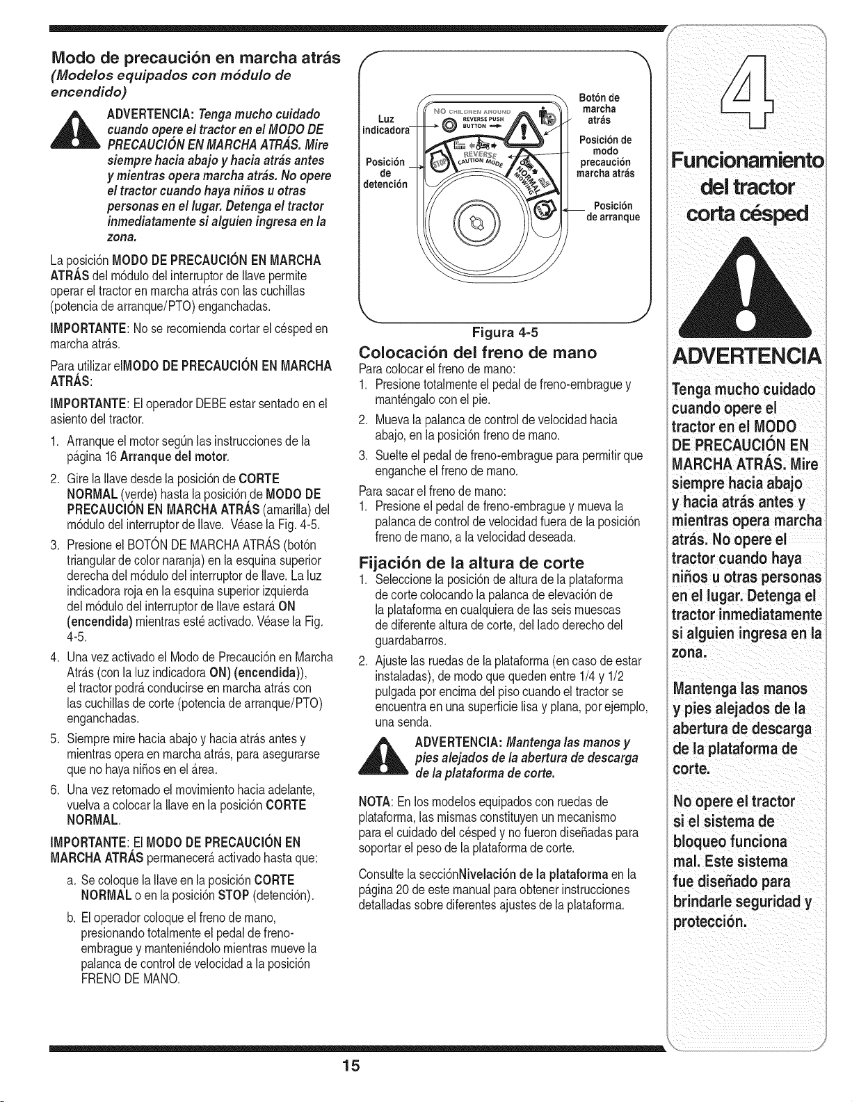
_!i_ii:_!ii_i_iiiii__I__i_ii_i__ _ _!__//i_
Modo de precauci6n en marcha atr_s
(Mode/os equipados con rn6du/o de
encendido)
,_ ADVERTENClA:Tengamucho cuidado
cuando opereel tractor en el MODODE
PRECAUCIONEN MARCHAATRAS.Mire
siempre hacia abajo y hacia atr&santes
y mientras opera marcha atr&s. No opere
el tractor cuando haya nifios u otras
personas en el lugar. Detengael tractor
inmediatamentesi alguien ingresa en la
zona,
La pqsici6nMODO DEPRECAUCIONEN MARCHA
ATRASdel m6dulodel interruptorde llavepermite
operarel tractoren marchaatr&scon lascucNlas
(potenciade arranque/PTO)enganchadas.
IMPORTANTE:Nose recomiendacortarel cespeden
marchaatr&s.
ParautilizareIMODODEPRECAUCIONEN MARCHA
ATRAS:
IMPORTANTE:EloperadorDEBEestarsentadoenel
asientodeltractor.
.
2.
.
Arranqueel motorsegOnlas instruccionesde la
p_gina16Arranquedel motor.
Girela Ilavedesdela posici6ndeCORTE
NORMAL(verde)hasta la posici6n.deMODODE
PRECAUCIONEN MARCNAATRAS(amarilla)del
m6dulodel interruptorde Ilave. V_asela Fig.4-5.
Presioneel BOTONDE MARCHAATRA,S (bot6n
triangularde color naranja)en laesquinasuperior
derechadel m6dulodelinterruptorde Ilave.La luz
indicadorarojaen la esquinasuperiorizquierda
delm6dulodel interruptorde Ilaveestar_.ON
(encendida) mientrasest_activado.Wase la Fig.
4-5.
4. Unavezactivadoel Modode Precauci6nen Marcha
Atr_.s(conla luzindicadoraON) (encendida)),
eltractorpodr_,conducirseen rnarchaatr_.scon
las cuchillasdecorte(potenciadearranque/PTO)
enganchadas.
5. Siempremirehaciaabajo y haciaatr_.santesy
mientrasoperaen marchaatr_.s,paraasegurarse
queno hayani_osen el_.rea.
6. Unavezretornadoel movimientohaciaadelante,
vuelvaa colocarla Ilaveenla posici6nCORTE
NORMAL.
IMPORTANTE:ElMODODE PRECAUClONEN
MARCHAATRASpermanecer&activadohastaque:
a. SecoloquelaIlaveen la posici6nCORTE
NORMALo en la posici6nSTOP(detenci6n).
b. Eloperadorcoloqueel frenode mano,
presionandototalmenteel pedaldefreno-
embraguey manteni_ndolomientrasmuevela
palancade controlde velocidada laposici6n
FRENODE MANO.
Luz
Posici6n
de
detenci6n
Bot6n de
marcha
atras
Posicibnde
modo
precauci6n
marcha atr_s
Posici6n
de arranque
Figura 4=5
Colocaci6n del freno de mano
Paracolocarelfreno de mano:
1. Presionetotalmenteel pedaldefreno-embraguey
mant_ngaloconel pie.
2. Muevala palancade controlde velocidadhacia
abajo,en la posici6nfrenode mano.
3. Suelteel pedalde freno-ernbragueparapermitirque
engancheel frenode mano.
Parasacarel frenode rnano:
1. Presioneel pedalde freno-embraguey muevala
palancade controlde velocidadfuerade la posici6n
frenode mano,a lavelocidaddeseada.
Fijaci6n de la altura de corte
1. Seleccionela posici6nde alturade laplataforma
de cortecolocandola palancadeelevaci6nde
laplataformaencualquierade las seis muescas
de diferentealturade corte,del ladoderechodel
guardabarros.
2. Ajustelas ruedasde la plataforma(en casodeestar
instaladas),de modoque quedenentre1/4 y 1/2
pulgadaporencimadel pisocuandoel tractorse
encuentraen una superficielisa y plana,por ejemplo,
unasenda.
,_ ADVERTENCIA:Mantenga las manos y
pies alejados de la abertura de descarga
de la plataforma de corte.
NOTA:Enlos modelosequipadoscon ruedasde
plataforma,las mismasconstituyenun mecanismo
parael cuidadodel cespedy no fuerondiseSadaspara
soportarel pesode laplataformade corte.
Consultela secci6nNivelaci6nde la plataforma enla
p_.gina20 deestemanualparaobtenerinstrucciones
detalladassobrediferentesajustesde laplataforma.
ADVERTENCIA
Tenga mucho cuidado
cuando opere el
tractor en el MODO
DE PRECAUClON EN
MARCHA ATRAS. Mire
siempre hacia abajo
y hacia atr_s antes y
mientras opera marcha
atr_s. No opere el
tractor cuando haya
niSos u otras personas
en el lugar. Detenga el
tractor inmediatamente
si alguien ingresa en la
zona,
Mantenga las manos
y pies alejados de la
abertura de descarga
de la plataformade
corte.
No opere el tractor
si el sisterna de
bloqueofunciona
rnal. Este sistema
fue diseSado para
brindade seguridad y
proteccion.
15
ADVERTEN
contraalg_n objeto
extraho,detengael
motor, desconecte
el(los) cable(s) dela
bujia y conecteel motor
a masa;Inspeccione
minuciosarnentepara
vet si la m_quina est_
da_ada: Repareel
da_o antes de volver
a encender el motor y
operarla m_quina,
Evite arrancar
subltamentei
desarrollar excesiva
velocidad y detenerse
de repente;
No abandone el
asiento del tractor sin
colocarprimerola
palanca de la potencia
de arranque PTO
(enganchede cuchilla
en la posici6n(OFF)
(desenganchada),
presionandoel pedal
del freno y colocandoel
freno de mano: Si deja
el tractor sin vigilancial
tambi_n gire la llave .de
encendido a la poslclon
off (apagado)y retirela;
Siempre mire hacia
antes y mientras se
desplaza marcha
atr_s, paraevitar un
Arranque del motor
ADVERTENClA:No opereel tractor si el
_ istema de bloqueo funciona real Este
sistemaruedisefiado para brindarle
seguridad y protecci&n.
NOTA:Consultela secci6nMONTAJEDELTRACTOR
enla p_.gina8 de este manualparaobtener
instruccionessobreelIlenadode aceitey gasolina.
1. Insertela Ilavedel tractorenel m6dulodel interruptor
deencendido.
.
.
4.
5.
Coloquelapalancade lapotenciade arranque
(PTO)(enganchedecuchilla)en la posici6nOFF
(desconectada).
Coloqueel frenode manodel tractor.
Activeel controldel cebador.
Girelallavedeencendidoenel sentidode las agujas
delrelojhastalaposici6nSTART(ARRANQUE).Una
vezquearranqueel motor,sueltela Ilave.Volver_.a la
posici6nON (odecortenormal).
IMPORTANTE:NOmantengalaIlaveenla posici6n
START(ARRANQUE)durantem_.sdediezsegundos
porvez.SiIo hace,puedeocasionardaSosal arrancador
el_ctricodelmotor.
6. Despu_sde quearranqueel motor,desactiveel
controldel cebadory coloqueelcontroldelcebador
enposici6nFAST(velocidadr_.pida).
NOTA:NOdeje el controldel cebadoractivadomientras
operaeltractor.SiIo hace,segenerar_,unamezcla
"rica"de combustibles,Iocualhar_.que el motorpierda
intensidad.
Detenci6n del motor
,d_ ADVERTENClA:Despu#sdegolpear contra
_ lg#n objeto extra#o,detengael motor,
desconecteel(los) cable(s)de labujia
y conecteel motor a masa.Inspeccione
minuciosamentepara versi la m#quina est#
dafada. Repareel da#oantesdevolvera
arrancarel motor y operar la m#quina
1. Silas cuchillasestanenganchadas,coloquela
palancadela potenciadearranque(PTO)(enganche
decuchilla)en la posici6nOFF(desconectada).
2. GirelaIlavedeencendidoen sentidocontrarioalas
agujasdel reloja laposici6nSTOP(detenci6n).
3. RetirelaIlavedelinterruptorde encendidoparaevitar
quealguienenciendaaccidentalmenteel motor.
Conducci6n del tractor
ADVERTENCIA:Evitearrancars#bitamente,
desarrollarexcesivavelocidady detenersederepente.
_ DVERTENClA:No abandone el asiento
del tractor sin colocar primero la palanca
de la potencia dearranque PTO(enganche
de cuchilla)en la posicibn (OFF)
(desenganchada),presionando el pedal
de/frenoy colocando el frenode mano.
Si dejael tractor sin vigilancia,tambi#n
gire la I/avede encendidoa la posicibn off
(apagado)y retirela.
Siempremire hacia abajo y hacia atr#s
antesy mientras se desplaza marcha
arras,para evitar unaccidente.
ADVERTENCIA
EVITE LESIONES PERSONALES GRAVES O
LA MUERTE
EN LAS PENDIENTESCONDUZCAHACIAARRIBA Y HACIA
ABAJO, NO DE FORMATRANSVERSAL.
EVlTE MANIOBRASDEGIRO BRUSCAS.
NO OPERELA UNIDAD ENAREAS DONDEPUEDEDERRAPAR
0 LADEARSE.
SI LA MAQUlNA SEDETIENEAL SUBIRLA PENDIENTE,
DETENGALAS CUCHILLASY RETROCEDALENTAMENTE
BAJANDO LA PENDIENTE.
NO CORTEEL CESPEDCUANDOHAYANI_IOSU OTRAS
PERSONASCERCA.
NUNCA TRANSPORTENI_IOS,AUN CON LAS CUCHILLAS
DESCONECTADAS.
MIRE HAClA ABAJOY HACIA ATRASANTESY MIENTRAS
OPERA ENMARCHAATRAS.
MANTENGATODOSLOS DISPOSITIVOSDE SEGURIDAD
(PROTECClONES,ESCUDOSE INTERRUPTORES)ENSU
LUGAR Y EN CORRECTOFUNCIONAMIENTO.
RETIRE LOSOBJETOS QUE PUEDANSER ARROJADOSPOR
LA(S) CUCHILLA(S).
CONOZCALA UBICAClONY FUNClON DETODOS LOS
CONTROLES.
ASEGURESEDEQUE LAS CUCHILLASY EL MOTORSE
DETENGANANTESDE COLOCARLAS MANOS0 LOS PIES
CERCADE LAS CUCHILLAS.
ANTESDE ABANDONAR LA POSICIONDEL OPERADOR,
DESENGANCHELASCUCHILLAS,COLOQUE LA PALANCADE
CAMBIOSEN POSICIONNEUTRAL,COLOQUEEL FRENODE
MANO, APAGUEEL MOTORY RETIRE LA LLAVE.
LEA EL MANUAL DEL OPERADOR
1. Presioneel pedalde frenoparasoltarel frenode mano
y dejeque subael pedal.
2. Muevala palancadel reguladorala posici6nFAST
(VELOCIDADRAPIDA,representadaporunaliebre).
3. Coloquelapalancade cambiosen posici6nde
MARCHADIRECTAo MARCHAATRAS.
IMPORTANTE:NOuse la palancade cambiospara
cambiarladirecci6nde desplazamientomientraseJtractor
est_enmovimiento.Siempreuseel pedal de freno para
detenerel tractorpor completoantesde hacerel cambio.
4. Suelteelfrenode manopresionandoel pedalde
freno-embraguey colocandola palancade controlde
velocidaden la posici6ndeseada.
IMPORTANTE:Losoperadoresqueconduzcaneltractor
por primeravezdeben usarlas posicionesdevelocidad1
6 2. Familiaricesecompletamentecon el funcionamiento
deltractory loscontrolesantes de hacerfuncionarel
tractorenposicionesde velocidadm_.salta.
5. Suelteel pedalde freno-embraguelentamentepara
poneren marchala unidad.
6. El tractorcorta cesped sedetienepresionandoel
pedaldefreno-embrague.
NOTA:Cuandose opera la unidadinicialmente,habr_.
unapequeSadiferenciaentrelas dosvelocidadesm_.s
altashastaque se asientenlas correasen las poleas,
duranteel periodode ablande.
16
ADVERTENCIA:Antes de abandonar la
posici6n de operador per cualquier razSn,
desenganche/as cuchillas, coloque la
palanca de eatables en neutral, co/oque
el freno de mane,apague el motor y retire
la Ilave.
IMPORTANTE:Siernprequedetengael tractorper
cualquierraz6nen un _.reade c_sped,hagaIo siguiente:
1. Coloquela palancadecarnbiosen neutral,
2. Coloqueel frenode mane,
3. Apagueel motory retirela Ilave.
Eso perrnitir_,reduciral minirnola posibilidadde que su
cespedresulte"quernado"perel escapecalientedel
motordeltractoren funcionarniento.
Si la unidad se detiene con el controlde velocidaden
velocidadalta,o si la unidadnofuncionacon la palanca
decontrolde velocidaden posici6ndevelocidadbaja,
hagaIosiguiente:
1. Coloquela palancadecarnbiosen NEUTRAL.
Vuelvaa arrancarel motor..
3.
Coloquela palancadecontrol de velocidaden la
posici6ndevelocidadrn_.salta.
4. Sueltecornpleltarnenteel pedal del freno-ernbrague.
5. Presioneelpedaldelfreno-ernbrague.
6. Coloquela palancadecontrol de velocidaden la
posici6ndeseada.
7. Coloquela palancadecarnbiosen MARCHA
DIRECTAo MARCHAATRAS,y siga los
procedirnientosnorrnalesdeoperaci6n.
Operaci6n en pendientes
Consultela secci6nINDICADORDE PENDIENTEen
la p_.gina3 paradeterrninaren qu_ pendientespuede
operarel tractorde rnanerasegura.
_ DVERTENClA:No corte el c#sped
en inclinaciones mayores a 15grades
(elevaciSnaproximadade 2 1/2pies per
cada 10pies). El tractor podria voltearse y
causar /esionesseveras.
• Corte haciaarriba y abajo de las pendientes,NUNCA
enforrnatransversal.
Tengacuidadocuandocarnbiede direcci6nal operar
la rn_.quinaen pendientes.
Est_atentoa loshoyos,surcos,baches,rocas,u
otrosobjetosocultos.El terrenodesniveladopuede
voltearla rn_.quina.El c_spedalto puedeocultar
obst_.culos.
Eviterealizargiros cuandoopereenunapendiente.
Sidebierarealizarungiro,baje de la pendiente.
Realizarun giro rnientrasse conducecuestaarriba
aurnentaenorrnernentelasposibilidadesde que el
vehiculod_unavueltade carnpana.
Evitedetenersecuandosubaunapendiente.Sifuese
necesariodetenersernientrassubeunapendiente,
arranquesuavey cuidadosarnentepara reducirla
posibilidadde que el tractord_ unavolteretahacia
atr_.s.
Enganche de las cuchillas
AIengancharla potenciade arranque(PTO)(enganche
decuchilla)se surninistraalirnentaci6na la plataforrna
decorteo a otrosaccesorios(disponiblesperseparado).
Paraconectarlas cuchillas,hagaIo siguiente:
1. Muevalapalancade controldel reguladora la
posici6nFAST(VELOCIDADR_,PIDA,representada
perunaliebre).
2. Tomela palancade the potenciade arranque(PTO)
(enganchede cuchilla)y girelatotalrnentehacia
adelantea la posici6nON (enganchada).
3. Mantengalapalancadel reguladoren la posici6n
FAST(velocidadr_.pida;representadaper una liebre),
parael use rn_.seficazde la plataforrnade corte o de
otrosaccesorios(disponiblesperseparado).
IMPORTANTE:Modelos con mode de precauci6nen
marchaatr;_s:Elmotorseapagar_,autorn_.ticarnentesi
lapotenciadearranque(PTO)est,.enganchadaconla
palancadecarnbiosen posici6nde rnarchaatr_.scon la
Ilavede encendidoen la posici6ndeCORTENORMAL.
Modelos sin mode de precauci6nen marcha atr_s:
Lapalancade la potenciade arranque(PTO)
(enganchede cuchilla)debeestarenposici6nOFF
(desenganchada)al arrancarel motor,desplazarseen
rnarchaatr_.sy cuandoel operadorabandonael asiento.
SFIbConsulteInterruptoresde bloqueodeseguridaden
lap_.gina14.
Utilizaci6n de la palanca de
elevaci6n de la plataforma
Paralevantarlaplataforrnade corte,rnuevala palanca
deelevaci6nde la plataforrnahaciala izquierda,luego
col6quelaen la rnuescarn_.sconvenienteparasu
aplicaci6n.ConsulteAjustede la alturade corteunas
p_.ginasatr_.sen esta rnisrnasecci6n.
17
ADVERTENCIA
No corte el cesped en
inclinacionesmayores
a 15 grades (elevaci6n
aproximada de 2
1/2 pies per cada 10
pies). El tractor podria
voltearse y causar
lesionesseveras.
Cortede cesped ADVERTENCIA" ADVERTENCIA:Paraayudara evitar
lesidn por alg_n objeto quesea EVITE LESIONES PERSONALES GRAVES
ADVERTENCIA
Para ayudar a evitar
el contacto con
las cuchillas o una
lesion por algun
objeto que sea
arrojado, mantenga
a las personas que
Io observan, a los
ayudantes, niSos y
mascotas alejados al
menos 25 metros de la
m_quina mientras est_
en funcionamiento.
Detenga ia m_quina si
alguien traspasa este
radio de seguridad.
Planifique el patrbn
de corte para evitar
que la descarga
de materiales se
realice hacia los
caminos, las veredas,
los observadores,
etc. Evite adem_s
descargar material
contra las paredes y
obstrucciones que
podrian provocar
que el material
descargado rebote
contra el operador.
arrojado, mantenga a/as personas que
Io observan, a los ayudantes,ni_os
y mascotas alejados al menos 25
metros de la m#quina mientras est# en
funcionamiento. Detengala m#quina si
alguien traspasa este radio de seguridad.
La siguienteinforrnaci6nser_.de utilidadcuandousela
plataforrnade cortecon su tractor:
_ DVERTENCIA:Planifique el patrSn
de corte para evitar que la descarga de
materiales se realice hacia los caminos,
/as veredas, los observadores, etc. Evite
adem_sdescargar material contra /as
paredes y obstrucciones que pod#an
provocar que el material descargado
rebote contra el operador.
• No cortea alta velocidadde piso,especialrnentesi
se hainstaladounjuegode abonadorao uncolector
dec_sped.
• Paraobtenerlos rnejoresresultados,se recornienda
realizarlos dos prirneroscortesde cespedarrojando
ladescargahaciael centro.Despu_sde lasdos
prirnerasvueltas,carnbiela direcci6nparaarrojarla
descargahaciaafuera,paraequilibrarel corte. Esto
otorgar_,unrnejoraspectoal cesped.
• No corteel c_speddernasiadocorto. El cespedcorto
es propicioparael crecirnientode rnalezas,y se
poneamarillor_.pidarnentecuandoescaseala lluvia.
• El corte del cesped siernpredeberealizarsecon el
reguladordelmotoral rn_.xirno.
• En terrenosdificiles, puederesultarnecesariopasar
porsegundavezel tractorcortac_spedsobreel
_.reayacortada,paraobtenerun corte rn_.sprolijo.
• NO intentecortar rnalezasfrondosaso c_sped
extrernadarnentealto. El tractorrue diseSadopara
cortarelcesped,NOparapodarrnalezas.
• Mantengalas cuchillasafiladas,y reernpl_.celas
cuandosedesgasten.Consultela secci6n
Cuchillas de corte en la p_.gina25de estemanual
paraobtenerinstruccionessobrec6rnoafilar
correctarnentelas cuchillas.
O LA IVlUERTE
• EN LAS PENDIENTESCONDUZCAHACIAARRIBA Y
HACIAABAJO, NO DE FORMATRANSVERSAL.
• EVlTE MANIOBRASDEGIRO BRUSCAS.
• NO OPERELA UNIDAD ENAREAS DONDEPUEDE
DERRAPARO O LADEARSE.
• SI LA M,_QUINASEDETIENEAL DESPLAZARSE
CUESTAARRIBA,DETENGALA(S) CUCHILLA(S)
Y CONDUZCAMARCHAATRAS,CUESTAABAJO,
LENTAMENTE.
• NO CORTEEL C¢SPED CUANDOHAYAMINOSU
OTRAS PERSONASESTENCERCA.
,, NUNCA TRANSPORTENI_IOS,AUN CON LAS
CUCHILLASDESCONECTADAS.
• MIRE HACIAABAJO Y HACIAATRASANTESY
MIENTRASOPERA EN MARCHAATRAS.
,, MANTENGATODOSLOS DISPOSITIVOSDE
SEGURIDAD(PROTECCIONES,ESCUDOSE
INTERRUPTORES)EN SULUGARY EN CORRECTO
FUNClONAMIENTO.
,, RETIRE LOSOBJETOS QUE PUEDANSER
ARROJADOSPORLA(S) CUCHILLA(S).
,, CONOZCALA UBICAClONY FUNClON DETODOS LOS
CONTROLES.
,, ASEGURESEDE QUE LAS CUCHILLAS Y EL MOTOR
SE DETENGANANTESDE COLOCARLAS MANOS0
LOS PIESCERCADE LA(S) CUCHILLA(S).
,, ANTESDE ABANDONARLA POSICIONDEL
OPERADOR,DESEN GANCHELAS CUCHILLAS,
COLOQUE LA PALANCADE CAMBIOS EN POSICION
NEUTRAL,COLOQUE ELFRENO DE MANO,APAGUE
EL MOTORY RETIRELA LLAVE.
LEA EL MANUAL DEL OPERADOR
18
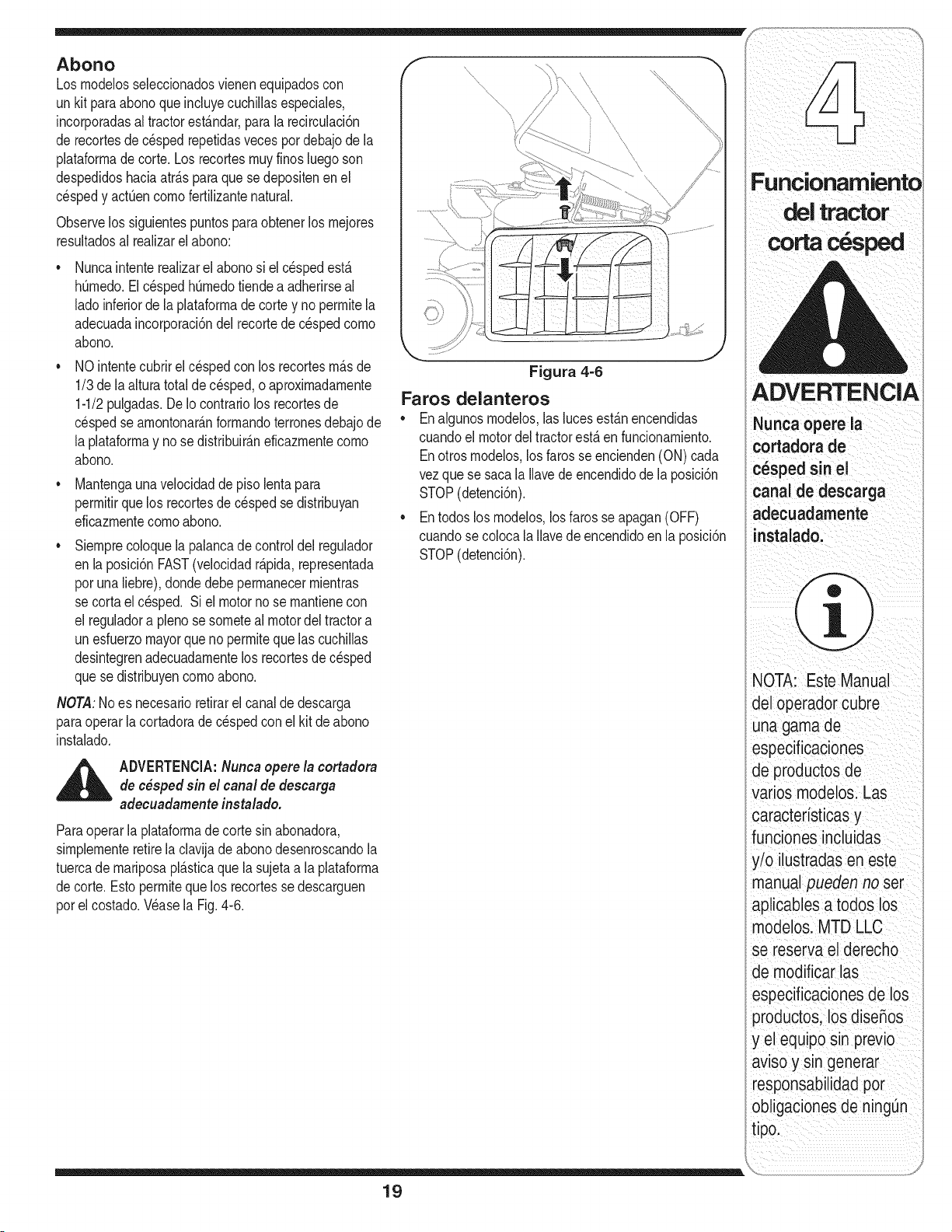
Abono
Los rnodelosseleccionadosvienenequipadoscon
un kit para abonoque incluyecuchillasespeciales,
incorporadasal tractorest_.ndar,para la recirculaci6n
de recortesde c_sped repetidasveces pot debajode la
plataforrnade corte.Los recortesrnuyfinosluegoson
despedidoshaciaatr_.sparaquese depositenen el
cespedy actOencornofertilizantenatural.
Observelos siguientespuntospara obtenerlos rnejores
resultadosal realizarel abono:
Nuncaintenterealizarel abonosi el c_spedest,.
hOrnedo.ElcespedhQrnedotiendea adherirseal
ladoinferiorde la plataforrnadecortey no perrnitela
adecuadaincorporaci6ndelrecortede cespedcorno
abono.
NO intentecubrirel cespedcon los recortesrn_.sde
1/3 de laalturatotal de cesped,o aproxirnadarnente
1-1/2pulgadas.De Iocontrariolos recortesde
cespedse arnontonar_.nforrnandoterronesdebajode
la plataforrnay no sedistribuir_.neficazrnentecorno
abono.
Mantengaunavelocidadde pisolentapara
perrnitirquelos recortesde cesped se distribuyan
eficazrnentecornoabono.
Siernprecoloquelapalancade controldel regulador
en la posici6nFAST(velocidadr_.pida,representada
porunaliebre),dondedebeperrnanecerrnientras
se cortaelc_sped. Si el motornose rnantienecon
el reguladora plenose sorneteal motordel tractora
unesfuerzomayorqueno perrniteque lascuchillas
desintegrenadecuadarnentelos recortesdec_sped
quese distribuyencornoabono.
NOTA:No es necesarioretirarel canal de descarga
paraoperarlacortadoradecespedconel kit deabono
instalado.
_ DVERTENCIA:Nunca opere la cortadora
de c_sped sin el canal de descarga
adecuadarnenteinstalado.
Paraoperarlaplataforrnade corte sin abonadora,
sirnplernenteretirela clavijade abono desenroscandola
tuercade rnariposapl_.sticaque lasujetaa laplataforrna
decorte. Estoperrnitequelos recortesse descarguen
porel costado.Wase la Fig.4-6.
Figura 4=6
Faros delanteros
• Enalgunosrnodelos,las lucesest&nencendidas
cuandoel motordel tractorest,. en funcionarniento.
Enotrosrnodelos,los farosseencienden(ON) cada
vezquese sacala Ilavede encendidode la posici6n
STOP(detenci6n).
• Entodos los rnodelos,los farosse apagan(OFF)
cuandose colocala Ilavede encendidoen la posici6n
STOP(detenci6n).
19
ADVERTENCI
cortadora de
c6spedsinel
i
canal de descarga
adecuadamente
NOTA: Este Manual
del operador cubre
unagamade
especificaciones
de productos de
varios modelos. Las
caracteristicas y
funciones incluidas
!/o ilustradas en este
manual pueden no set
_tplicablesa todos los
modelos. MTD LLC
se reserva el derecho
de modificar las
especificaciones de los
productos, los diseSos
y el equipo sin previo
awso y s_ngenerar
responsabilidadpot
obligaciones de ningQn
tipo.
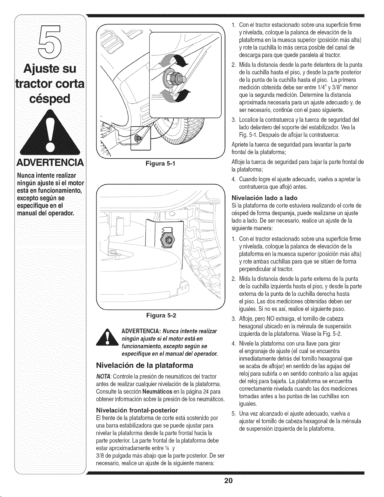
ADVERTENCIA
Nunca intente realizar
ningun ajuste si el motor
esta en funcionamiento,
excepto segun se
especifique en el
manual deJ operador.
Figura 5-1
1. Conel tractorestacionadosobreuna superfide firme
y nivelada,coloquela palancade elevaci6nde la
plataforrnaen la muescasuperior(posid6n m_.salta)
y rotelacuchillaIom_.scercaposiNedel canalde
descargaparaquequedeparalelaal tractor.
2. Midala distanda desdela partedelanterade la punta
dela cuchillahasta el piso, y desdela parteposterior
dela puntade lacuchillahastael piso. Laprimera
medici6nobtenidadebeser entre 1/4"y 3/8" menor
quela segundamedici6n.Determinela distancia
aproximadanecesariaparaun ajusteadecuadoy, de
ser necesario,continQecon el pasosiguiente.
3. Localicelacontratuercay la tuercade seguridaddel
ladodelanterodel soportedelestabilizador.Veala
Fig.5-1.Despu_sde aflojarla contratuerca:
Aprietela tuercade seguridadparalevantarlaparte
frontalde la plataforma;
Aflojelatuercade seguridadpara bajarla partefrontalde
la plataforma;
4. CuandoIogreelajusteadecuado,vuelvaaapretarla
contratuercaqueafloj6antes.
;,...........
__j
Figura 5=2
,_ ADVERTENCJA:Nunca intente realizar
ning#n ajuste si el motor est# en
funcionamiento, excepto seg#n se
especifique en el manua/ del operador.
Nivelaci6n de la plataforma
NOTA:ControJelapresi6nde neumAticosdel tractor
antesde realizarcualquiernivelaci6nde la plataforma.
Consultela secci6nNeum_ticos en la p&gina24para
obtenerinformaci6nsobrela presi6nde los neum&ticos.
Nivelaci6n frontal-posterior
Elfrentedela plataformade corte est&sostenidopor
unabarraestabilizadoraque se puedeajustarpara
nivelarlaplataformadesdela partefrontal haciala
parteposterior.La partefrontalde la plataformadebe
estaraproximadamenteentre1_y
3/8 depulgadam_.sabajoque la parteposterior.Deser
necesario,realiceun ajuste de la siguientemanera:
Nivelaci6n lado a lado
Si la pJataformade corteestuvJerarealJzandoel corte de
c_speddeformadespareja,puederealizarseunajuste
ladoa lad& De sernecesario,realiceun ajustede la
siguientemanera:
1. Conel tractorestacionadosobreuna superficiefirme
y niveJada,coloquela palancadeelevaci6nde la
plataformaen la muescasuperior(posici6nm_.salta)
y roteambascuchillaspara que se sitQende forma
perpendicularal tractor.
2. Midala distanciadesdela parteexternade la punta
dela cuchillaizquierdahastael piso,y desdela parte
externadela puntade la cuchilladerechahasta
el piso. Lasdos medicionesobtenidasdebenser
iguales.Sino es asi, realiceel siguientepaso.
3. Afloje,peroNOextraiga,eltornillodecabeza
hexagonalubicadoen la m_nsulade suspensi6n
izquierdade la plataforma.Wase la Fig.5-2.
4. Nivelela plataformacon una Ilaveparagirar
el engranajede ajuste(el cualse encuentra
inmediatamentedetr&sdeltornillohexagonalque
se acabadeaflojar)ensentidode lasagujasdel
relojparasubNao en sentidocontrarioalas agujas
del relojpara bajarJa.La plataformase encuentra
correctamenteniveladacuandolasdos mediciones
tomadasantesalas puntasde lascuchillasson
iguales.
5. Unavezalcanzadoel ajusteadecuado,vuelvaa
ajustarel tornillode cabezahexagonalde la m_nsula
desuspensi6nizquierdade la plataforma.
20
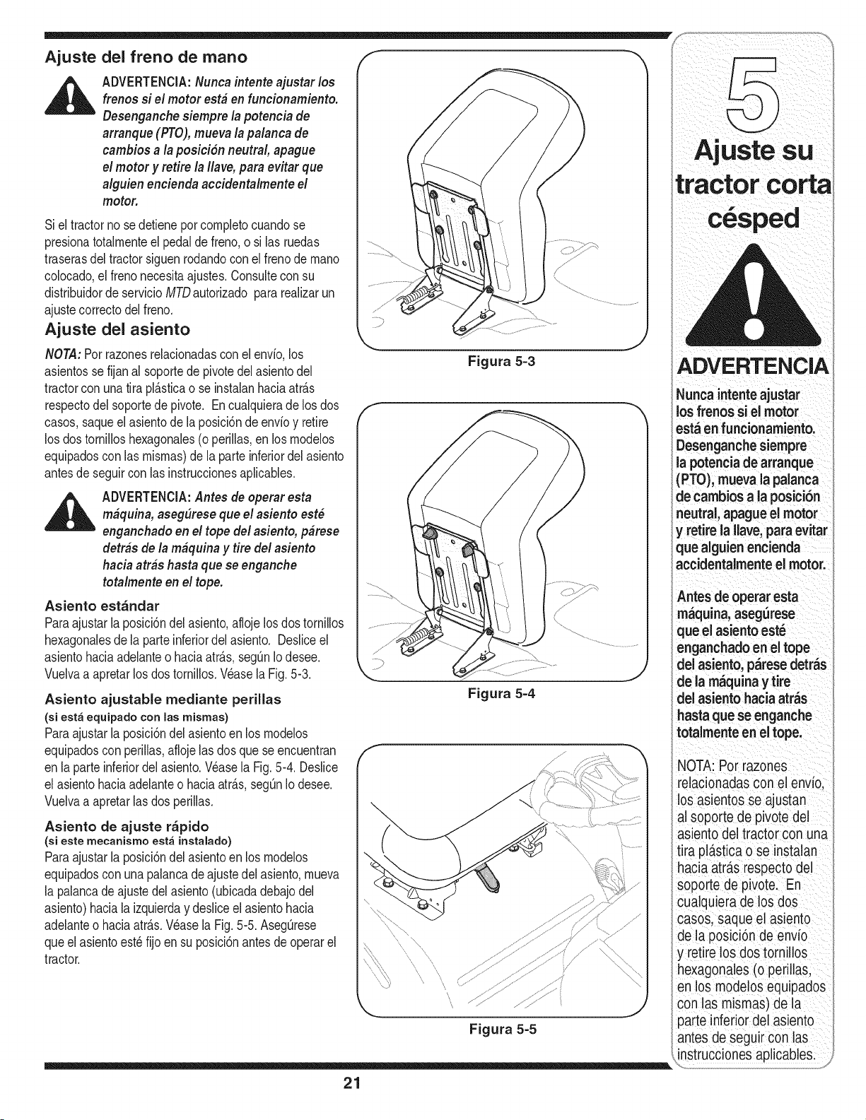
del freno de mano
Ajuste
ADVERTENClA:Nuncaintente ajustar los
frenos si el motor est&en funcionamiento.
Desenganehesiempre la potencia de
arranque (FRO),mueva la palanca de
cambios a la posici6n neutral, apague
el motor y retire la Ilave,para evitar que
alguien eneiendaaceidentalmente el
motor.
Si el tractornose detieneporcornpletocuandose
presionatotalrnenteel pedalde freno,o si lasruedas
traserasdel tractorsiguenrodandocon elfrenode rnano
colocado,el frenonecesitaajustes.Consulteconsu
distribuidorde servicioMTDautorizadopara realizarun
ajustecorrectodelfreno.
Ajuste del asiento
NOTA:Porrazonesrelacionadascon elenvio,los
asientossefijan al soportede pivotedel asientodel
tractorcon unatira pl&sticao se instalanhaciaatr&s
respectodel soportede pivote. Encualquierade los dos
casos,saqueel asientode laposici6ndeenvioy retire
los dos tornilloshexagonales(o perillas,en los rnodelos
equipadoscon las rnisrnas)de la parte inferiordelasiento
antesdeseguircon las instruccionesaplicables.
ADVERTENCIA:Antes de operar esta
m&quina,aseg(Irese que el asiento est_
enganehado en el tope del asiento, p&rese
detr&s de la m&quinay tire del asiento
hacia arras hasta que se enganehe
totalmente en el tope.
Asiento est_ndar
Paraajustarla posici6ndel asiento,aflojelosdos tornillos
hexagonalesde la parteinferiordelasiento. Desliceel
asientohaciaadelanteo haciaatr&s,segQnIodesee.
Vuelvaa apretarlos dostornillos.Wase la Fig.5-3.
Asiento ajustable mediante perillas
(si est_ equipado con las mismas)
Paraajustarla posici6ndel asientoenlos rnodelos
equipadoscon perillas,aflojelas dos que se encuentran
en la parteinferiordel asiento.Wase la Fig.5-4. Deslice
el asientohaciaadelanteo haciaatr&s,segQnIodesee.
Vuelvaa apretarlas dosperillas.
Asiento de ajuste r_pido
(si este rnecanismo est_ instalado)
Paraajustarla posici6ndel asientoenlos rnodelos
equipadoscon unapalancade ajustedel asiento,rnueva
la palancade ajustedelasiento(ubicadadebajodel
asiento)haciala izquierday desliceel asientohacia
adelanteo haciaatr&s.Wase la Fig. 5-5. AsegQrese
queel asientoest_ fijo en su posici6nantesde operarel
tractor.
\
Figura 5=3
Figura 5=4
f
\
ADVERTENCIA
Nunca intenteajustar
losfrenos si el motor
est_ en funcionamiento:
Desenganche siempre
la potencia de arranque
(PTO)i mueva la palanca
dne cambios a la posici6n
eutral, apague el motor
y retire la Ilave, para evitar
que aiguien encienda
accidentalmente el motor.
Antesde operaresta
maquina, asegurese
que el asiento est_
enganchado en el tope
del asiento, parese detras
de la m_quina y tire
del asiento hacia atras
asta que se enganche
otalmente en el tope.
NOTA: Por razones
relacionadas con el envio,
los asientos se ajustan
al soporte de pivote del
asiento del tractor con una
tira plastica o se instalan
hacia atr_.srespecto del
soporte de pivote. En
cualquiera de los dos
casos, saque el asiento
de la posici6n de envio
y retire los dos tornillos
hexagonales (o perillas,
en los modelos equipados
con las mismas) de la
parte inferior del asiento
antes de seguir con las
instrucciones aplicables.
21
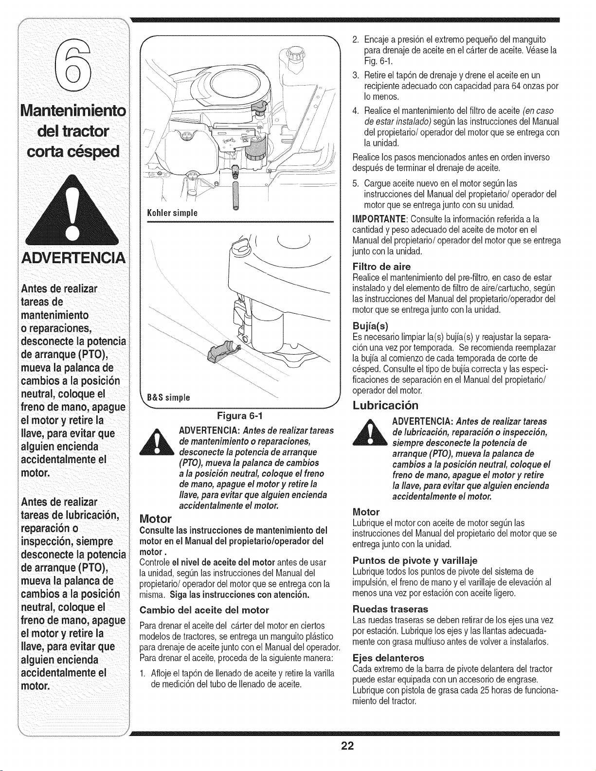
Manteni
corta
ADVERTENCIA
Antes de realizar
tareas de
mantenimiento
o reparaciones,
desconecte ia potencia
de arranque (PTO),
mueva la paianca de
carnbiosa ia posicibn
neutral, coloque el
freno de rnano, apague
ei motor y retire la
ilave,para evitar que
alguien encienda
accidentalmente el
motor.
Antes de reaiizar
tareas de iubricaci6n,
reparacibn o
inspecci6n, siempre
desconecte la potencia
de arranque (PTO),
ueva ia paianca de
cambios a ia posici6n
eutral, coloque el
freno de mano, apague
el motor y retire ia
iiave,para evitar que
aiguien encienda
accidentaimente ei
motor.
Kohlersimple
_S simple j
Figura 6=1
_ DVERTENCIA:Antes de rea/izar tareas
de mantenimiento o reparaciones,
desconecte la potencia dearranque
(PTO),mueva la palanca de cambios
a la posici6n neutral, coloque el freno
de mano, apague el motor y retire la
#ave,para evitar que alguien encienda
accidentalmente el motor.
Motor
Consulte lasinstruccionesde mantenimiento del
motor en el Manualdel propietario/operadordel
motor.
Controleel nivel de aceitedel motor antes de usar
la unidad,seg_nlas instruccionesdel Manualdel
propietario/operadordel motorque se entregacon la
rnisrna.Siga las instruccionescon atenci6n.
Cambio del aceite del motor
Paradrenarel aceitedel c&rterdelmotoren ciertos
rnodelosde tractores,se entregaun rnanguitopl&stico
paradrenajede aceitejuntocon el Manualdeloperador.
Paradrenarel aceite,procedade lasiguienternanera:
1. Aflojeeltap6n deIlenadode aceite y retirela varilla
de rnedici6ndel tubo de Ilenadode aceite.
2. Encajea presi6nel extrernopeque5odel rnanguito
paradrenajede aceiteen el c_.rterde aceite.V6asela
Fig.6-1.
3. Retireel tap6nde drenajey drene el aceiteen un
recipienteadecuadoconcapacidadpara64 onzaspor
Io rnenos.
.
Realiceel mantenirnientodelfiltrodeaceite (en caso
de estarinstalado)segOnlas instruccionesdel Manual
delpropietario/operadordelmotorque seentregacon
la unidad.
Realicelos pasosrnencionadosantes en orden inverso
despu_sde terrninarel drenajedeaceite.
5. Cargueaceitenuevoen el motorsegOnlas
instruccionesdelManualdel propietario/operadordel
motorquese entregajuntocon su unidad.
IMPORTANTE:Consultela inforrnaci6nreferidaa la
cantidady pesoadecuadodelaceitede motoren el
Manualdel propietario/operadordel motorquese entrega
junto con la unidad.
Filtro de aire
Realiceel rnantenirnientodel pre-filtro,en caso de estar
instaladoy del elernentode filtrodeaire/cartucho,segOn
las instruccionesdelManualdel propietario/operadordel
motorquese entregajuntocon la unidad.
Bujia(s)
Es necesariolirnpiarla(s) bujia(s)y reajustarla separa-
ci6nunavezporternporada.Se recorniendareernplazar
la bujiaal cornienzodecadaternporadade cortede
c_sped.Consulteel tipode bujia correctay lasespeci-
ficacionesde separaci6nen el Manualdel propietario/
operadordel motor.
Lubricaci6n
ADVERTENCIA:Antes de rea/izar tareas
de lubricaci6n, reparaci6n o inspecci6n,
siempre desconecte la potencia de
arranque (PTO),mueva la palanca de
cambios a la posici6n neutral, co/oque el
freno de mano, apague el motor y retire
la #ave,para evitar que alguien encienda
accidenta/mente el motor.
Motor
Lubriqueel motorcon aceitede motorsegOnlas
instruccionesdelManualdel propietariodel motorquese
entregajuntocon la unidad.
Puntos de pivote y varillaje
Lubriquetodoslos puntosde pivotedel sisternade
irnpulsi6n,el frenode rnanoy elvarillajedeelevaci6nal
rnenosunavezporestaci6ncon aceiteligero.
Ruedas traseras
Las ruedastraserassedebenretirarde los ejesunavez
porestaci6n.Lubriquelos ejesy las Ilantasadecuada-
rnentecongrasa rnultiusoantesdevolvera instalarlos.
Ejes delanteros
Cadaextrernode la barra de pivotedelanteradel tractor
puedeestarequipadacon un accesoriode engrase.
Lubriquecon pistolade grasacada25 horasde funciona-
rnientodeltractor.
22
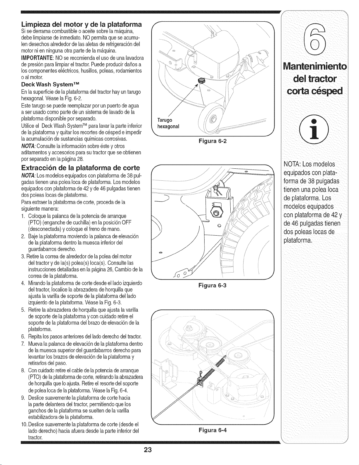
Limpieza del motor y de la plataforma
Sise derrarnacombustibleo aceitesobrela rn_.quina,
debelirnpiarsede inrnediato.NO perrnitaque se acurnu-
lendesechosalrededordelasaletasde refrigeraci6ndel
motornienningunaotrapartede la rn_.quina.
IMPORTANTE:NOse recorniendael usode una lavadora
depresi6nparalirnpiareltractor.Puedeproducirda_osa
loscornponentesel_ctricos,husillos,poleas,rodarnientos
oal motor.
Deck Wash System TM
Enlasuperficiedela plataforrnadel tractorhayuntarugo
hexagonal.Wase la Fig.6-2.
Estetarugose puedereernplazarpor un puertodeagua
a serusadocornopartedeunsisternadelavadode la
plataforrnadisponibleporseparado.
Utiliceel DeckWashSystemTM paralavarla parteinferior
dela plataforrnay quitarlos recortesde c_spede irnpedir
laacurnulaci6ndesustanciasquirnicascorrosivas.
NOT.4:Consultela inforrnaci6nsobreestey otros
aditarnentosy accesoriosparasu tractorque seobtienen
porseparadoen la p_.gina28.
Extracci6n de la plataforma de corte
NOTA:Losrnodelosequipadosconplataforrnade 38 pul-
gadastienenuna poleaIocade plataforrna.Losrnodelos
equipadoscon plataforrnade 42 y de46 pulgadastienen
dospoleasIocasde plataforrna.
Paraextraerla plataforrnade corte,procedadela
siguienternanera:
1. Coloquela palancade la potenciade arranque
(PTO)(enganchedecuchilla)enla posici6nOFF
(desconectada)y coloqueelfrenode rnano.
2. Bajela plataforrnarnoviendola palancade elevaci6n
dela plataforrnadentrola rnuescainferiordel
guardabarrosderecho.
3. Retirela correade alrededorde la poleadelmotor
deltractory dela(s) polea(s)Ioca(s).Consultelas
instruccionesdetalladasen lap_.gina26, Carnbiode la
correadela plataforrna.
4. Mirandola plataforrnade cortedesdeel ladoizquierdo
deltractor,Iocalicelaabrazaderade horquillaque
ajustalavarilladesoportede la plataforrnadel lado
izquierdodelaplataforrna.Wase la Fig.6-3.
5. Retirelaabrazaderadehorquillaqueajustalavarilla
desoportede la plataforrnay concuidadoretireel
soportede la plataforrnadel brazode elevaci6nde la
plataforrna.
6. Repitalospasosanterioresdelladoderechodeltractor.
7. Muevala palancade elevaci6nde laplataforrnadentro
dela rnuescasuperiordel guardabarrosderechopara
levantarlos brazosdeelevaci6nde la plataforrnay
retirarlosdelpaso.
8. Concuidadoretireel cablede la potenciadearranque
(PTO)delaplataforrnade corte,retirandolaabrazadera
dehorquillaqueIoajusta.Retireelresortedelsoporte
depoleaIocade la plataforrna.Wasela Fig.6-4.
9. Deslicesuavernentela plataforrnadecortehacia
lapartedelanteradeltractor,perrnitiendoquelos
ganchosdela plataforrnasesueltende lavarilla
estabilizadorade la plataforrna.
10.Deslicesuavernentela plataforrnade corte (desdeel
ladoderecho)haciaafueradesdela parteinferiordel
tractor.
Figura 6=2
Figura 6=3
Figura 6=4
23
NOTA: Los modelos
_quipadoscon plata-
forma de 38 pulgadas
tienen una polea Ioca
de plataforma. Los
modelos equipados
con plataforma de 42 y
de 46 pulgadas tienen
dos poleas Iocasde
plataforma.
ADVERTENCIA
Nunca exceda la
presi6n m_xima de
inflado que se indica
en los laterales de los
neum_ticos.
AI cargarse, las
baterias emiten un
gas que puede causar
explosiones. Cargue
la bateria en un _rea
bien ventilada, y
al_jela de una llama
abierta o luz piloto,
como pot ejemplo
calentadores de
agua, calefactores
de ambiente, hornos,
secadores de ropa u
otros aparatos a gas.
Para el reemplazo
utilicesiempre un
fusible que posea la
misma capacidad de
amperaje.
Neum_ticos
_ DVERTENCIA:Nunca excedala presi6n
m&ximade infladoquese indicaen los
laterales de los neum&ticos.
Lapresi6noperativarecornendadaparalosneurn_.ticoses:
• Aproxirnadarnente10psi para los neurn_.ticos
traseros
• Aproxirnadarnente14psi para los neurn_.ticos
delanteros
IMPORTANTE:Consultelos lateralesde las ruedas
paraconocercon exactitudlapresi6nmaximaen psi
recornendadaporel fabricante.No inflelos neurn_.ticos
enexceso.Unapresi6nde neurn_.ticosdespareja
podriahacerque la plataforrnacorte el c_spedenforrna
desigual.
Bateria
La bateriaest,. selladay nonecesitarnantenirniento.
Los nivelesde _.cidono sepuedencontrolar.
• Siernprernantengalirnpiosy libresde acurnulaci6nde
elernentoscorrosivoslos cablesy los bornesde la
bateria.
• Despu_sde lirnpiarla bateriay los bornes,aplique
unacapadelgadadevaselinao grasaa arnbos
bornes.
• Siernprernantengalos capuchonesdegorna
colocadossobreel bornepositivoparaprevenirun
cortocircuito.
IMPORTANTE:Si por alguna raz6nextrae la bateria,
desconecteprirneroel cableNEGATIVO(negro)de su
borney a continuaci6nel cable POSlTIVO(rojo).Cuan-
dovuelvaa instalarlabateria,conectesiernpreprirnero
elcable POSITIVO(rojo)a su borne,y a continuaci6n
elcable NEGATIVO(negro).AsegQresequelos cables
est_nconectadosa los bornescorrectos,ya que si los
carnbiase podriainvertirlapolaridady provocarun
daSoal sisternaalternadordel motor.
Carga de la bateria
IMPORTANTE:Cuandocarguelabateriade sutractor,
utiliceQnicarnenteuncargadordiseSadoparabaterias
de plorno-_.cidode 12V.Lealapartedel Manualdel
propietariocorrespondienteal cargadorde la bateria
antesde cargarla bateriadel tractor.Siernpresigalas
instruccionesy tengaencuentalasadvertencias.
Si sutractorno se hautilizadoduranteun periodode
tiernpoprolongado,carguelabateriade la siguiente
rnanera:
• Ajusteel cargadordebateriaparaqueproduzca
un m_.xirnode 10amperes.Si el cargadorde su
bateriaes autorn_.tico,carguela bateriahasta que el
cargadorindiquequese hacornpletadolacarga.
NOTA:Siel cargadornoes autorn_.tico,carguepor
ochohorascornorninirno.
,_ ADVERTENCIA:AI cargarse, las bate#as
emiten un gas quepuede causar
explosiones. Carguela bateria en un &rea
bien ventilada, y al_jela de una llama
abierta o luz piloto, como por ejemplo
calentadores deagua, calefactores de
ambiente, homes, secadores de ropa u
otros aparatos a gas.
Arranque pot medio de cone×i6n en puente
,_ ADVERTENCIA:Cuando retire o instalela
bate#a, siga estas instruccionespara evitar
que el destomillador cause un cortocircuito
al entrar en contacto con laplataforma.
IMPORTANTE:Nuncaconecteen puentela bateria
agotadadeltractorcon la bateriade un vehiculoen
funcionarniento.
1. Conecteel extrernode uncablede puenteal borne
positivode la baterfaen buenestado,luegoel otro
extrernoal bornepositivode la bateriaagotada.
2. Conecteel otrocablede puenteal bornenegativo
dela bateriaenbuenestado,luegoal marco de la
unidad con la batedaagotada.
3. Pongaen marcha el tractor seg_n se indicaen la
p_gina15.
_ DVERTENClA:$i no se utiliza este
procedimiento se puedenproducir chispas
y podria explotar elgas de cualquiera de
las baterias.
Limpieza
Lirnpielabateriaretir_.ndoladel tractory lav_.ndolacon
unasoluci6ndeaguay bicarbonato.Si es necesario,
raspelos bornesde la bateriacon un cepillode alarnbre
paraquitarlosdep6sitos.Recubralos bornesy loscables
expuestoscongrasao vaselinapara prevenirla corrosi6n.
Desperfectos de la bateria
A continuaci6nse rnencionanalgunascausascornunes
dedesperfectosen las baterias:
• activaci6ninicialincorrecta • cargainsuficiente
• excesode carga • corrosi6nen las
conexiones
• congelarniento
Estos desperfectos NO est_ncubiertos potla
garantia del tractor.
Fusible
Enel rnazode cablesde sutractorhay un fusiblede 20
amperesinstaladoparaprotegerel sisternael_ctricodel
tractordedaSoscausadospor excesode arnperaje.
Siel sisternaelectricono funciona,o el motorde su trac-
tor noarranca,verifiqueprirneroque el fusible no se haya
quernado.Lo podr_,encontrardebajodel cap6 rnontado
detr_.sdel panelde instrurnentosdel ladoderecho.
,_ ADVERTENCIA:Parael reemplazo utilice
siempre un fusible que posea la misma
capacidad de amperaje.
24
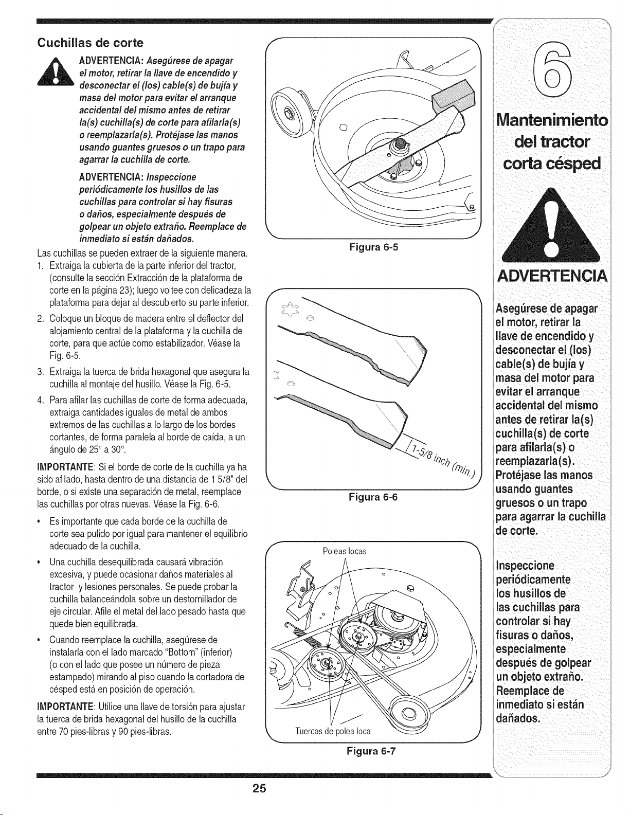
i_i i _i_I :_ ii iii
Cuchillas de corte
ADVERTENClA:Aseg(_resedeapagar
el motor, retirar la #avede encendido y
desconectar el (los) cable(s) de bujia y
masadel motor para evitar elarranque
accidental del mismo antes de retirar
la(s) cuchilla(s) de torte para afilarla(s)
o reemplazarla(s). Prot_jaselas manos
usando guantes gruesos o un trapo para
agarrar la cuchilla de corte.
ADVERTENClA:Inspeccione
peri6dicamenteloshusillos de las
cuchillas para controlar si hay fisuras
o dafios, especialmente despu_s de
golpear un objeto extra_o. Reemplace de
inmediato si est&n dafiados.
Lascuchillasse puedenextraerdela siguienternanera.
1. Extraigala cubiertade la parteinferiordel tractor,
(consultela secci6nExtracci6nde la plataforrnade
corteenla p_.gina23); luegovoltee condelicadezala
plataforrnaparadejaral descubiertosu parteinferior.
2. Coloqueun bloquede rnaderaentreel deflectordel
alojarnientocentraldela plataforrnay la cuchillade
corte,paraqueact_ecornoestabilizador.V_asela
Fig.6-5.
3. Extraigala tuercade brida hexagonalqueasegurala
cuchillaal rnontajedel husillo.Wase la Fig.6-5.
4. Paraafilar lascuchillasde corte de forrnaadecuada,
extraigacantidadesigualesde metal de arnbos
extrernosde lascuchillasa Iolargode los hordes
cortantes,deforrnaparalelaal hordede caida,aun
_.ngulode250a 30°.
IMPORTANTE:Siel bordede cortede la cuchillaya ha
sidoafilado,hastadentrode una distanciade 1 5/8" del
horde,o si existeunaseparaci6nde metal,reernplace
las cuchillasporotrasnuevas.Wase la Fig.6-6.
• Es irnportanteque cada hordede la cuchillade
corteseapulidoporigualpararnantenerel equilibrio
adecuadode la cuchilla.
• Unacuchilladesequilibradacausar_,vibraci6n
excesiva,y puedeocasionardaSosrnaterialesal
tractor y lesionespersonales.Se puedeprobarla
cuchillabalance_.ndolasobreundestornilladorde
ejecircular•Nile el metaldel lado pesadohasta que
quedebienequilibrada.
• Cuandoreernplacela cuchilla,asegQresede
instalarlacon el lado rnarcado"Bottom"(inferior)
(o conel ladoqueposeeunnQrnerode pieza
estarnpado)rnirandoal pisocuandola cortadorade
cespedest,.enposici6ndeoperaci6n.
IMPORTANTE:UtiliceunaIlavede torsi6npara ajustar
latuercadebridahexagonaldel husillode la cuchilla
entre70pies-librasy 90pies-libras.
Figura 6-5
f
Figura 6-6
PoleasIocas
Tuercasde
Figura 6-7
ADVERTENCIA
Asegurese de apagar
el motor, retirar la
lave de encendido y
desconectar el (los)
cable(s) de bujia y
masa del motor para
evitar el arranque
accidental del mismo
antes de retirar la(s)
cuchiHa(s) de corte
para afilarla(s) o
reemplazarla(s).
Prot_jase las manos
usando guantes
gruesos o un trapo
para agarrar la cuchilla
de corte.
lnspeccione
peri6dicamente
los husiHos de
las cuchiHas para
controlar si hay
fisuras o dafios,
especialmente
despues de golpear
un objeto extrafio.
Reemplace de
inmediatosi est_n
dafiados.
25
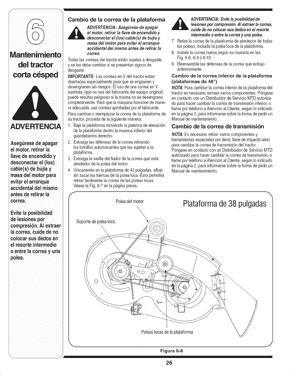
,&
Cambio de la correa de la plataforma ADVERTENCIA:Evite/aposibilidadde
lesionespor compresiSn.AI extraerla correa,
,_ ADVERTENClA: Aseg(_resede apagar cuide de no colocarsus dedosen elresorteel motor, retirar la Ilavede encendido y intermedioo entre la correay una pole&
desconectar el (los) cable(s) de bujia y
masadel motor para evitar el arranque 7. Retirela correade la plataformadealrededordetodas
accidental del mismo antes de retirar la las poleas,incluidala polea Iocade laphtaforma.
correa. 8. InstalelacorreanuevasegQnse muestraen las
Todaslascorreasdeltractorest_.nsujetasa desgaste, Fig.6-8, 6-96 6-10.
y se las debecambiarsi se presentansignosde 9. Reensamblelasdefensasde la correaqueextrajo
desgaste, anteriormente.
IMPORTANTE:LascorreasenV del tractorest_.n Cambio de la correa inferior de la plataforma
diseSadasespecialmenteparaque seengraneny (plataformas de 46")
desengranensin riesgos.Eluso deunacorreaenV NOTA:Paracambiarla correainferiorde la plataformadel
sustituta(queno seadel fabricantedelequipooriginal) tractores necesarioextraervarioscomponentes.P6ngase
puederesultarpeligrososi la mismano se desengrana encontactocon un Distribuidorde Servido MTDautoriza-
completamente.Paraquela m&quinafuncionede mane- dopara hacercambiarla correade transmisi6ninferior,o
raadecuada,usecorreasaprobadasporelfabricante. Ilameportel_fonoa Atenci6nal Client& seg_nIoindicado
Paracambiaro reemplazarla correade la plataformade enla p_.gina2, parainformarsesobrela formade pedirun
su tractor,procedadela siguientemanera: Manualde mantenimiento.
1. Bajelaplataformamoviendola palancade elevaci6n Oambio de la correa de transmision
de la plataformadentrola muescainferiordel
guardabarrosderecho. NOTA:Es necesarioretirarvarioscomponentesy
2. Extraigalas defensasde la correaretirando herramientasespeciales(es decir,Ilavede impacto/aire)
los tornillosautoroscantesque las sujetana la paracambiarlacorreadetransmisi6ndeltractor.
plataforma. P6ngaseen contactoconun Distribuidorde ServicioMTD
autorizadoparahacercambiarla correade transmisi6n,o
3. Extraigalavarilladel fiadorde la correaque est,. Ilameportel_fonoaAtenci6nal Client& segQnIoindicado
alrededorde la polea del motor, en la p_.gina2, para informarsesobrela formade pedirun
4. Onicamenteen la plataformade 42 pulgadas,afioje Manualde mantenimiento.
sin sacarlas tuercasde la poleaIoca.Estopermitir_.
retirarf_.cilmentela correade las poleasIocas.
V_asela Fig. 6-7 en la p_.ginaprevia.
ADVERTENCIA
Asegurese de apagar
el motor, retirar la
Ilave de encendido y
desconectar el (los)
cable(s) de bujia y
masa dei motor para
evitar el arranque
accidental del mismo
antes de retirar ia
correa.
Evite la posibilidad
de lesiones pot
compresion. AI extraer
la correa, cuide de no
colocar sus dedos en
el resorte intermedio
o entre la correa y una
polea.
Poleadel motor
X
Soportede poleaIoca X
Plataformade38 pulgadas
©
PoleasIocasde la plataforma
Figura 6=8
26
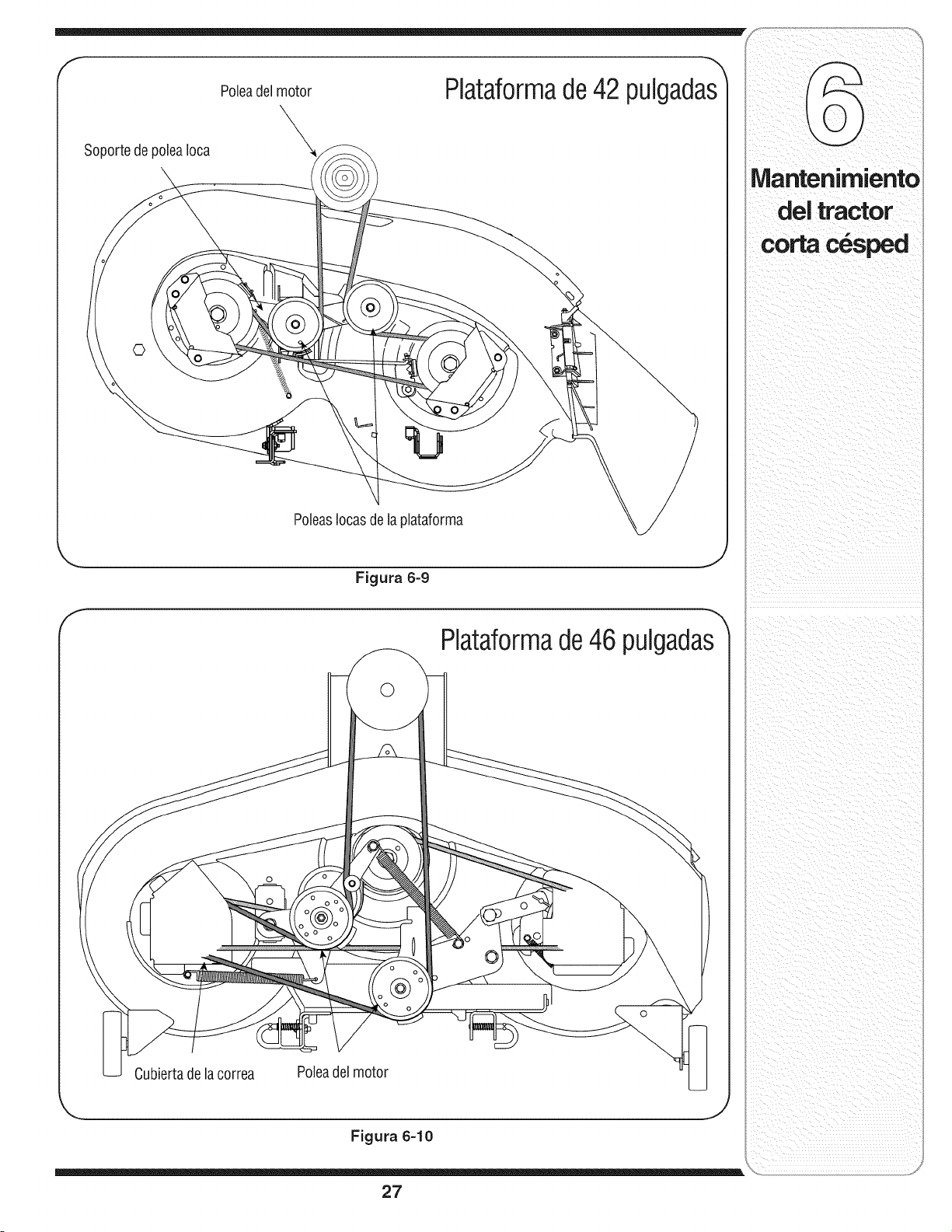
f
SoportedepoleaIoca
Poleadel motor
\
Plataformade42 pulgadas_
0
PoleasIocasde laplataforma
,.. j
Figura 6=9
f
Piataformade46 pulgadas
0
©
Cubiertadelacorrea Poleadel motor
Figura 6=10
27
lVlantenimiento
del tractor
corta c_sped
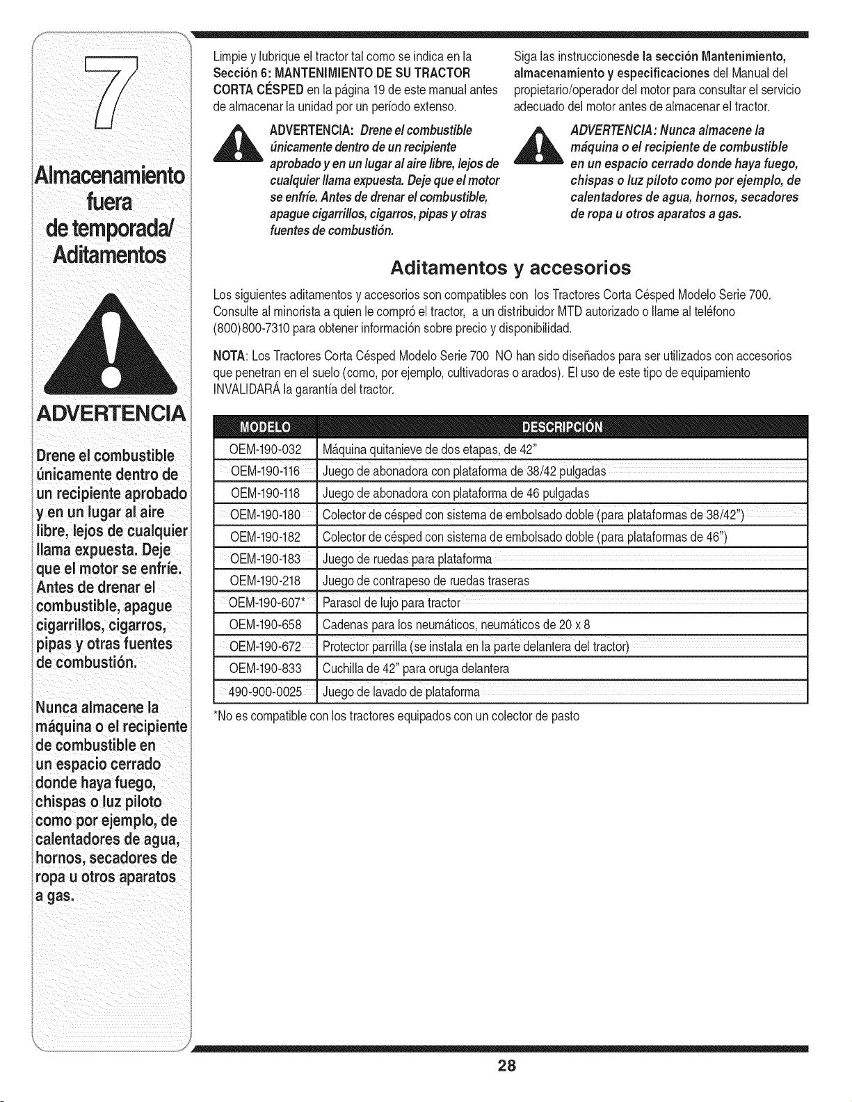
Alma namiento
ADVERTENCIA
Drene eJcombustible
_nicamente dentro de
un recipiente aprobado
y en un lugar al aire
libre, lejos de cuaJquier
llama expuesta. Deje
ique el motor se enfrie.
Antes de drenar el
' combustibJe, apague
i cigardllos, cigarros,
i pipas y otras fuentes
i de combusti6n.
i Nunca almacene la
im_quina o el recipiente
de combustible en
un espacio cerrado
Idonde haya fuego,
chispas o luz piloto
como pot ejemplo, de
calentadores de agua,
i hornos, secadores de
iropa u otros aparatos
a gas.
Limpiey lubriqueeltractortal comose indicaen la
Secci6n 6: MANTENJMJENTODE SUTRACTOR
CORTACESPEDen la p_.gina19de estemanualantes
dealmacenarla unidadpor un periodoextenso.
,_ ADVERTENCJA:Dreneel combustible
#nicamentedentro deun recipiente
aprobadoyen un lugar a/aire libre, lejos de
cualquierllama expuesta.Dejequee/motor
se enfrie.Antesde drenarel combustible,
apaguecigarrillos,cigarros,pipas y otras
fuentesdecombusti6n.
SigalasinstruccionesdeJasecci6n Mantenimiento,
aJmacenamientoy especificaciones del Manualdel
propietario/operadordel motorpara consultarel servicio
adecuadodelmotorantesde almacenarel tractor.
_ ADVERTENCIA:Nuncaa/macene la
m#quina o el recipiente de combustib/e
en un espacio cerrado donde haya fuego,
chispas o luz piloto como pot ejemp/o, de
ca/entadoresde agua, homos, secadores
de ropa u otros aparatos agas.
Aditamentos y accesorios
Lossiguientesaditamentosy accesoriossoncompatiblescon losTractoresCorta C_spedModeloSerie 700.
Consulteal minoristaa quienlecompr6el tractor, a un distribuidorMTDautorizadoo Ilamealtel_fono
(800)800-7310paraobtenerinformaci6nsobreprecioy disponibilidad.
NOTA:LosTractoresCortaC_spedModeloSerie700 NO hansido diseSadospara serutilizadoscon accesorios
quepenetranenel suelo(como,porejemplo,cultivadorasoarados).Elusode este tipo de equipamiento
INVALIDAR_,lagarantiadel tractor.
0EM-190-032 M_.quinaquitanievede dosetapas,de 42"
0EM-190--1i6 ' Juegode abonadoraconplataformade 38/42 puigadaS
0EM-190-118 Juegode abonadoraconplataformade 46 pulgadas
OEM-19Oq80 ' Colectorde c_spedcon sistemade embolsadodObie(paraplataformasde38/42!')
0EM-190-182 Colectorde cespedcon sistemade embolsadodone (paraplataformasde46")
0EM-190-183 Juegode ruedasparaplataforma
0EM-190-218 Juegode contrapesode ruedastraseras
OEM-190-607" "Parasolde luj0 para tractor
0EM-190-658 Cadenasparalos neum_.ticos,neum_.ticosde20 x 8
-0EM-190:672 Protectorparrilla(se instalaen la partedelanteradel tractor)
0EM-190-833 Cuchillade 42"para orugadelantera
490--900-0025 Juegode lavadode plataforma
*Noes compatiblecon los tractoresequipadoscon un colectorde pasto
28
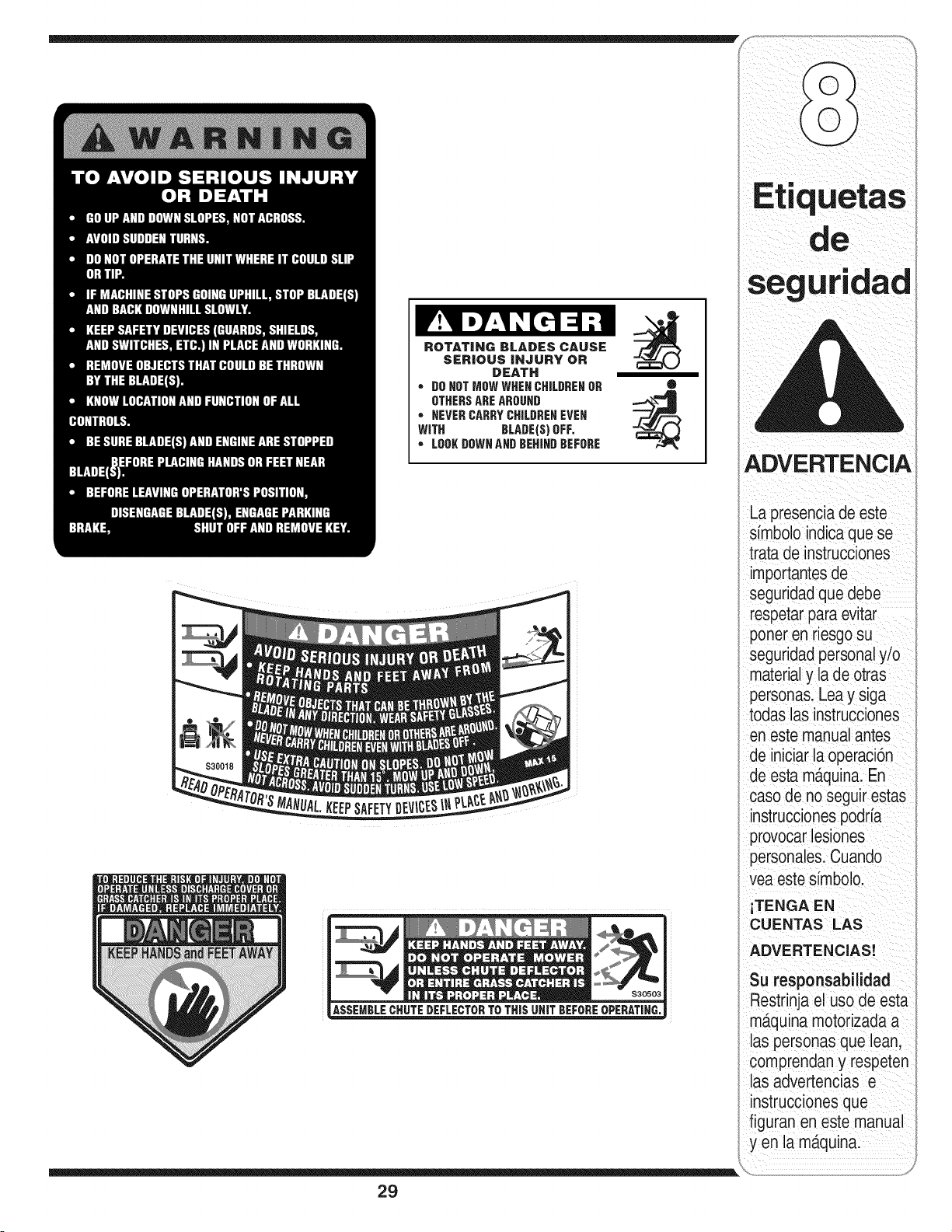
ROTATING BLADES CAUSE
SERIOUS INJURY OR
DEATH
• D0 HOTMOW WHEI CHILIREI OR
OTHERSAREAROOID
• lEVER CARRYCHILDREI EVEI
WITH BLADEIS) OFF.
• L001( DOWI AID IEHIID BEFORE
®
Etiquetas
ADVERTENCIA
La presenciade este
sfmbolo indicaque se
trata de instrucciones
importantesde
seguridadque debe
respetarpara evitar
poner en riesgosu
seguridadpersonaly/o
materialy la de otras
personas.Lea y siga
todas las instrucciones
en este manualantes
de iniciarla operaci6n
de esta mD.quina.En
caso de no seguir estas
instruccionespodrfa
provocarlesiones
personales.Cuando
vea este sfmbolo.
iTENGA EN
CUENTAS LAS
ADVERTENCIAS!
Su responsabilidad
Restrinja el uso de esta
aquina motorizadaa
las personas que lean,
comprendan y respeten
las advertencias e
instruccionesque
figuran en este manual
yen la maquina.
29
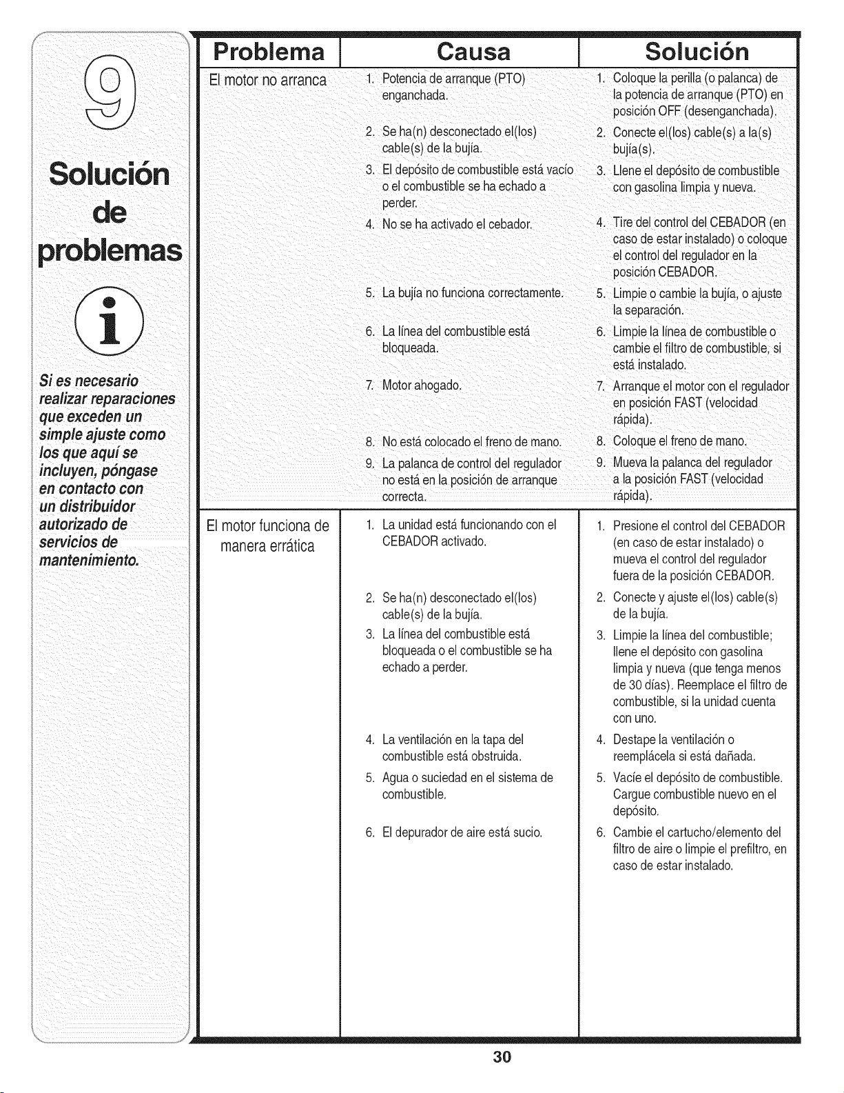
Problema Causa Soluci6n
Si i"
0 UC OR
de
problemas
Si es necesario
i realizarreparaciones
que exceden un
simple ajuste come
los que aqui se
incluyen, pSngase
en contacto con
un distribuidor
autorizado de
servicios de
I mantenimiento.
E motor no arranca 1. Potenciade arranque(PTO) 1. Coloquelaperilla(o palanca)de
enganchada, la potenciade arranque(PTO)en
posici6nOFF(desenganchada)
2. Seha(n) desconectadoel(los) 2. Conectee (los)cable(s) a la(s)
cable(s)de la bujia, bujia(s).
3. Eldep6sitodecombustibleest,.vacio 3. Lene el dep6sitode combustible
o el combustiblese ha echadoa con gasolinalirnpiay nueva.
perder.
4. No se ha activadoel cebador. 4. Tire del controldel CEBADOR(en
casode estar instaado) o coloque
el controldel reguladorenla
posici6nCEBADOR.
5. La bujia no funcionacorrectarnente. 5. Lirnpieo carnbiela bujia o ajuste
la separaci6n.
6. La lineadel Combustibleest& 6. Lirnpiela lineade cornbustbleo
bloqueada, cambieel filtro de cornbustble s
est#tinstalado.
7 Motorahogado. 7. Arranqueel motorconel regulador
en posici6nFAST(velocidad
r_tpida).
8. No est,. colocadoel frenode rnano. 8. Coloqueel frenode rnano.
9. La palancade controldel regulador 9. Muevala palancadel regulador
noestaen la posici6nde arranque a la posici6nFAST(velocidad
correcta, rapida).
Elmotorfuncionade
maneraerra.tica
1. La unidadesta funcionandocon el
CEBADORactivado.
2. Seha(n) desconectadoel(los)
cable(s)de la bujia.
3. La lineadel combustibleesta
bloqueadao el combustiblese ha
echadoa perder.
4. Laventilaci6nen la tapadel
combustibleest&obstruida.
5. Aguao suciedaden el sisternade
combustible.
6. Eldepuradorde aire est&sucio.
1. Presioneel controldelCEBADOR
(on casode estarinstalado)o
rnuevael controldel regulador
fuerade la posici6nCEBADOR.
2. Conectey ajusteel(los) cable(s)
de la bujia.
3. Lirnpiela lineadel combustible;
Ileneel dep6sitocon gasolina
lirnpiay nueva(quetengarnenos
de 30 dias). Reernplaceel filtro de
combustible,si launidadcuenta
con uric.
4. Destapela ventilaci6no
reernpl_.celasi est,.daSada.
5. Vacieel dep6sitode combustible.
CarguecornbustiNenuevoenel
dep6sito.
6. Carnbieel cartucho/elernentodel
filtrode aire o lirnpieelprefiltro,en
casode estar instalado.
30
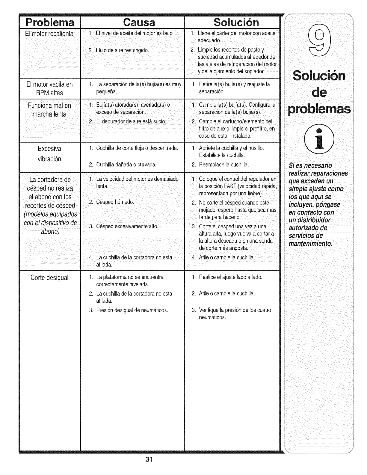
Problema Causa Sol uci6n
El motor recalienta El nive!de aceitedel motores bajoi ii L!eneel CArterdel motorConaceite
adeCuadol
21 Flujode aire restringido: 2, Lirnpielos recortesde pastoy
Suciedadacurnuladosalrededorde
!as aletasde refrigeraci6nde motor
y delalojarnientodelSoplador.
El motor vacila en
RPM altas
1. Laseparaci6ndela(s) bujia(s)es rnuy
pequeSa.
1. Retirela(s) bujia(s)y reajustela
separaci6n.
Func °nama en i: Bujia(S)at0rada(s)averiada(S)o !: cambie ia(s)bujia(s)!configure ia
m r n excesodeSeparac6n separac6nde a(s)bujia(s)
a cha le ta _
2iEI depuradordeaire estAsuciol Cambieeicartuchoielementode!
fi!tro deaire0 limpieel piefi!tro'en
casodeestarinstalado:
Excesiva 1. Cuchillade corteflojao descentrada. 1. Aprietela cuchillay el husillo.
vibraci6n Estabilicelacuchilla.
2. Cuchillada_adao curvada.
2. Reernplacela cuchilla.
La cortadora de 1. Lavelocidaddel motores dernasiado 1. Coloqueel controldel reguladoren
cesped"n o rea liza enta. a posc 6n.FAST(veoc.dad, rapda,
el abono con lOS representaaapor una ueDre).
r^^.r,_^ .^ ^- . 2. C#spedhOrnedo. 2 No cortee c6spedcuandoest6
UL;U tub LIU L;Ub_JULI .....
.... rnojaaoesperenastaquesea rnas
(moclelos equlpaaos tarde para hacero.
con el dispositivo de
3. C_spedexcesivarnentealto. 3. Corteel c_speduna vez a una
abono) alturaalta,luegovuelvaa cortara
Corte desigual
1. Laplataforrnano se encuentra
correctarnentenivelada.
2. La cuchillade la cortadorano estA
afilada.
3. Presi6ndesigualde neurnAticos.
1. Realiceelajusteladoa lado.
2. Afileo carnbiela cuchilla.
3. Verifiquelapresi6nde los cuatro
neurnAticos.
il i ii iiiiiii ill
!i _i_/_Iii_iiii_ii!_/_iii__i_I_I
_ ii i i
ii i i i
mas
Si es necesario
realizar reparaciones
que exceden un
simple ajuste como
los que aqui se
induyen, p6ngase
en contacto con
un distribuidor
autorizado de
servicios de
nantenimiento.
31
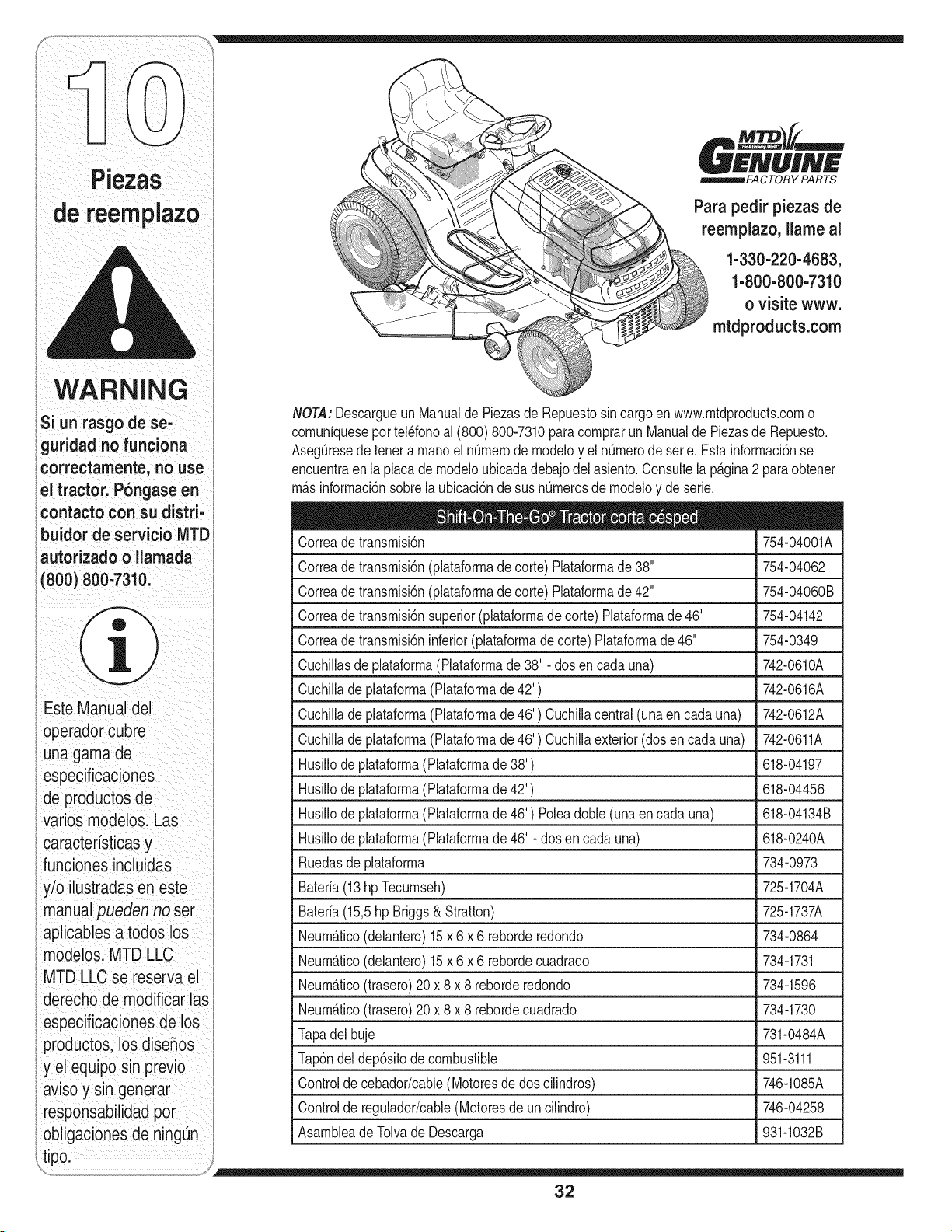
WARNING
!
si rasgo ese,
guridad.o fu"ciona
correctamente, no use
€ontacto con su distri'
buidor servicio MTD
autorizado o Uamada
(8oo)8oo 731o:
I _ ii i _ _ i__
)Este Manual del
Operador Cubre
una gama de
especificaciones
de produCtosde
ratios modelosl Las
caracteristiCas
funci°nes incluidas
y!o !lustradasen este
manual pueden no ser
aplicablesa todoslos
mOdeloslMTD LEO
MTD LLC se reserva ei
I
derecho de modlflcar las
especificacionesde los
productos los dise_os
y el equipo sinprevio
aviso y sin generar
resp
obligaciOnesde ningOn
Para pedir piezas de
reempiazo, liame al
1-330-220-4683,
1-800-800-7310
o visite www.
mtdproducts.com
NOTA:DescargueunManualde Piezasde Repuestosincargoen www.mtdproducts.como
comuniquesepor tel_fonoal (800) 800-7310paracomprarun Manualde Piezasde Repuesto.
AsegOresedetenera manoel nOmerode modeloy el nQmerode serie.Esta informaci6nse
encuentraen la placa de modeloubicadadebajodel asiento.Consulte(ap_.gina2 para obtener
m&sinformaci6nsobrela ubicaci6nde susnOmerosde modeloy de serie.
Correadetransmisi6n 754-04001A
Correadetransmisi6n(plataformade corte) Plataformade 38" 754-04062
Correadetransmisi6n(plataformade corte) Plataformade 42" 754-04060B
Correadetransmisi6nsuperior(plataformade corte)Piataformade 46" 754-04142
Correadetransmisi6ninferior(plataformade corte) Plataformade 46" 754-0349
Cuchillasde plataforma(Piataformade 38"- dos en cada una) 742-0610A
Cuchillade plataforma(Plataformade 42") 742-0616A
Cuchillade plataforma(Plataformade 46") Cuchillacentral(unaencada una) 742-0612A
Cuchillade plataforma(Plataformade 46") Cuchillaexterior(dosen cadauna) 742-0611A
Husillodeplataforma(Plataformade 38") 618-04197
Husillodeplataforma(Plataformade 42") 618-04456
Husillodeplataforma(Plataformade 46") Poleadoble(unaen cadauna) 618-04134B
Husil(odeplataforma(Plataformade 46"- dos encada una) 618-0240A
Ruedasde plataforma 734-0973
Bateria(13hpTecumseh) 725-1704A
Bateria(15,5hp Briggs& Stratton) 725-1737A
Neum_.tico(delantero)15 x 6 x 6 reborderedondo 734-0864
Neum&tico(delantero)15x 6 x 6 rebordecuadrado 734-1731
Neum_.tico(trasero)20 x 8 x 8 reborderedondo 734-1596
Neum_.tico(trasero)20 x 8 x 8 rebordecuadrado 734-1730
Tapadelbuje 731-0484A
Tap6ndel dep6sitode combustible 951-3111
Controlde cebador/cable(Motoresde dos cilindros) 746-1085A
Controlde regulador/cable(Motoresde uncilindro) 746-04258
Asambleade Tolvade Descarga 931-1032B
32

NOTAS
Utilice esta p_gina para tomar notas y escribir la informaci6n importante.
33

NOTAS
Utilice esta p_gina para tomar notas y escribir la informaci6n importante.
34
DECLARAClON DE GARANTJA DEL CONTROL DE LAS EMISIONES DE CALIFORNIA
DERECHOS Y OBLIGAClONES DE SU GARANTJA
ElConsejode RecursosA@eosde Californiay MTDConsumerGroupInc.se complacenen explicarla garanfiadel sistemade controlde emisionespor
evaporaci6nde su cortadorade cesped 2007.En California,lasnuevas maquinaspara cortarcespedse debendiseSar,construiry equiparde modode cumplir
con las rigurosasnormascontrala poluci6ndel estado.MTDConsumerGroupInc. debe garantizarel sistemade control de emisiones porevaporaci6n(EECS)
de su cortadorade cespedpot el periododetiempo indicadom_sabajo, siemprey cuandono exista uso incorrecto,negligenciani mantenimientoinadecuadode
dichacortadorade cesped.
Elsistema EECSpuedeincluir piezastales comoel carburador,el sistemade inyecci6nde combustible,el sistemade encendido,el convertidorcatalitico,
los dep6sitosde combustible,laslineas de combustible,lostaponesde combustible,las v_lvulas,contenedores,filtros, manguerasde vapor,abrazaderas,
conectoresyotros componentesafinesrelacionadoscon las emisiones.
Donde e×ista una condiei6n eubierta por la garantia, MTDConsumer Group Inc. reparar_ su eortadora de e_sped sin eosto alguno ineluyendoel
diagn6stieo, las piezas y la mano de obra.
COBERTURA DE LA GARANTJA DEL FABRICANTE:
Este sistemade control de emisionespot evaporaci6nse garantizaporel t@minode dos aSos.Si algunapartede su equipo relacionadacon lasemisionespot
evaporaci6nes defectuosa,MTDConsumerGroupInc. reparar_o sustituir_dicha parte.
RESPONSABILIDADES DEL PROPIETARIO SEGUN LA GARANTJA:
En su car_cterde propietariode la cortadorade cesped,ustedes responsabledel mantenimientorequeridoquese especificaen el manualdel propietario. MTD
ConsumerGroup Inc.le recomiendaqueconservetodos los recibosque cubrenel mantenimientode su cortadorade cesped, no obstanteIo cual MTDConsumer
GroupInc. no podr_denegarel cumplimientode lagaranfia Qnicamentepor lafalta delos recibos.
Comopropietariode la cortadorade cesped, usteddebe saberque MTDConsumerGroupInc. puededenegarla coberturade lagaranfia si su cortadorade
cespedo una piezade la mismafallandebido a uso incorrecto,negligencia,mantenimientoindebidoo a modificacionesno aprobadas.
Ustedes responsablede presentarlacortadorade cespedal centrode distribuci6no de mantenimientode MTDConsumerGroupInc.tan prontocomoaparezca
el problema.Las reparacionescubiertaspor lagaranfia se debenIlevara caboen un lapso razonableque no excedade 30 dias. Si tiene algunapregunta
respectodela coberturade lagaranfia, p6ngaseen contactocon el Departamentode Mantenimientode MTDConsumerGroupInc. al telefono1-800-800-7310.
COBERTURA DE LA GARANTJA DE EMISIONES GENERALES:
MTDConsumerGroupInc. garantizaal compradorfinal y a cadacompradorsubsiguienteque la cortadorade cesped: est_diseSada,construiday equipadade
modo de cumplircon todas las regulacionesaplicablesy quese encuentralibre de defectosde materialesy de fabricaci6nque pudierencausar lafalla de una
piezagarantizadaidentica,en todos los aspectosmateriales,a la piezadescriptaen lasolicitud de certificaci6nde MTDConsumerGroupInc.
El periodode garanfia comienzaen la fechade entregade lacortadora alcompradorfinal o en lafecha en que la m_quinase poneen funcionamientopot primera
vez. El periodode garanfiaes de dos aSos.
Sujetoa ciertas condicionesyexclusionesquese indicana continuaci6n,lagaranfia de laspiezas relacionadascon lasemisioneses la siguiente:
1. Cualquierpiezagarantizadaque no este programadaparaser reemplazadacomo partedel mantenimientorequeridoen las instruccionesescritas
suministradasse garantizapor el periodode garanfiaarribamencionado.Si la pieza falla duranteel periodode coberturadela garanfia, lamismaser_
reparadao reemplazadapor MTDConsumerGroupInc. de acuerdo con el p&rrafo(4) a continuaci6n.Cualquierpiezareparadao reemplazadasegQnla
garanfiase garantizar&potel restodel periodo de garanfia.
2. Cualquierpiezagarantizadaque este programadasolamentepara inspecci6nregularen lasinstruccionesescritassuministradasse garantizapot el periodo
de garanfia arribamencionado.Cualquierpieza reparadao reemplazadasegQnla garanfiase garantizar_por el restodel periodo.
3. Cualquierpiezagarantizadaque este programadapara reemplazosegQnel mantenimientorequeridode conformidadcon lasinstruccionesescritas
suministradas,se garantizapor el periodode tiempo anterior a la primerafecha de reemplazoprogramatic paraesa pieza.Si la piezafalla antesdel primer
reemplazoprogramatic,lamismaser_ reparadao reemplazadapot MTDConsumerGroupInc.de acuerdocon el p&rrafo(4) a continuaci6n.Cualquierpieza
reparadao reemplazadabajogaranfiase garantizar&pot el restodel periodo anterioral primerreemplazoprogramaticpuntualparaesa pieza.
4. La reparaci6no el reemplazode cualquierpieza garantizadadeconformidadcon lasdisposicionesde lagaranfia queaqui se estipulasedebe realizar en un
centrode servicio t@nico sin costoalgunopara el propietario.
5. Noobstantelas disposicionesque aqui se estipulan,losservicios o reparacionesbajogaranfiase suministrar_nen todos nuestroscentrosde distribuci6nbajo
franquiciademantenimientoparalos motoreso equipo en cuesti6n.
6. El propietariode lacortadorade cespedno deber_ pagareltrabajo de diagn6sticodirectamenteasociadoconuna piezagarantizadadefectuosaenrelaci6n
con las emisiones,siemprey cuandodichotrabajo de diagn6sticose realiceen un centrode garanfia.
7. MTDConsumerGroup Inc.es responsablepot daSosy perjuicioscausadosa otros componentesde motoreso equipo derivadosde la falla bajo garanfiade
cualquierpiezagarantizada.
8. Durantelatotalidaddel periodode garanfiade la cortadorade cespedarriba mencionado,MTDConsumerGroupInc. mantendr_unsuministrode piezasbajo
garanfiasuficienteparasatisfacerla demandaesperadade tales piezas.
9. Cualquierpiezade reemplazose podr&usarpara el cumplimientodel mantenimientoo reparacionesbajogaranfia, y sesuministrar_sincargo para el
propietario.Dichouso no reducir_ lasobligacionesdegaranfia de MTDConsumerGroupInc.
10.Nose podr&nusar piezasadicionalesni modificadasque no estenexentasde acuerdocon el Departamentode los Recursosdel Aire(Air ResourcesBoard).
El usode cualquierpiezaadicionalo modificadano exenta por el compradorfinal ser&causal de invalidezde losreclamosbajo garanfia.MTDConsumer
GroupInc. no tendr_ responsabilidadpot la garanfiade fallasde piezas garantizadasque fuerencausadaspot el uso de unapieza no exenta adicionalo
modificada.
PIEZAS GARANTIZADAS:
La reparaci6no el reemplazode cualquierpieza garantizadaquede otro modo pudieseestar cubiertapor lagaranfia podr_ser excluidade tal coberturade
garanfiasi MTDConsumerGroupInc.demuestraque la cortadorade cespedes objetode usoincorrecto,negligenciao mantenimientoinadecuado,y que tal
uso incorrecto,negligenciao mantenimientoinadecuadofue causadirecta de la necesidadde reparaci6no reemplazodedicha pieza.No obstanteIoantedicho,
cualquierajustede un componentecon un dispositivode limitaci6nde ajuste instaladoen f_brica y quefuncioneadecuadamente,podr_ set cubiertopot la
garanfia.La siguientelistade piezases cubierta pot la garanfia de emisiones:Linea de combustible,abrazaderasde la linea de combustible
GARANTiA LiMITADA DEL FABRICANTE PARA
La siguientegaranfialimitadaes otorgadaporMTD LLCcon respecto
a nuevosproductosadquiridosy utilizadosen EstadosUnidos,sus
territoriosy posesiones.
"MTD"garantizaeste productocontra defectosen los materialesy
manodeobraporun periodode dos (2) aSosa partirde lafecha
decompraoriginaly,a su opci6n, reparar_,o reemplazar_.,sin costo
aiguno,cualquierpiezaque presentedefectosen los materialeso
manodeobra. Estagarantialimitadas6iose aplicar_,si el producto
ha sidooperadoy mantenidode acuerdocon las instruccionesdel
Manualdel Operadorque se proporcionaconel productoy no ha sido
sujetoa uso inapropiado,abuso,uso comerciai,abandono,accidente,
mantenimientoincorrecto,alteraci6n,vandalismo,robo,incendio,
inundaci6no algOndaSodebidoaotro peligroo desastrenatural.El
daSoresultantepor la instaiaci6no el uso depiezas,accesorioso
aditamentosno aprobadospor MTDpara su uso conel(los) producto(s)
incluido(s)enestemanualanular_,la garanfiaen Ioque respectaa
esosdaSos.
Segarantizaque las piezascon desgastenormalest_.niibresde
defectosen los materialesy manode obraporun periodode treinta
(30)dias a partirde ia fechade compra.Las piezaso componentes
sujetosa desgastenormalincluyenperono selimitana: baterias,
correas,cuchillas,adaptadoresdecuchillas,bolsasdecesped,
ruedasde plataforma,asientos,zapatasde deslizamientode m_.quina
quitanieve,placasde raspado,gomashelicoidalesy neum_.ticos.
COMO SOLiCITAR Y OBTENER SERVIClO TECNICO: El
servicio de la garantia est&disponible, CON PRUEBA DE
COMPRA, a trav_s de su distribuidor local autorizado para el
mantenimiento. Para Iocalizarel distribuidor de su Area,consulte
las P_.ginasAmarillas o p6ngase en contacto con MTD LLC en
RO. Box 361131,Cleveland, Ohio 44136-0019,o comuniquese por
tel_fono a los numeros 1-800-800-7310o 1-330-220-4683 o visite
nuestro sitio Web en www.mtdproducts.com.
Estagaranfialimitada no suministracoberturaen lossiguientescasos:
a. El motoro las piezascomponentesdel mismo.Estoselementos
puedenestargarantizadospor el fabricantepor separado.Consulte
los t_rminosy condicionesen la garantiacorrespondientedel
fabricante.
b. Las bombasrompetroncos,v_.ivulasy cilindrostienenuna garantia
separadade un aSo.
c. Loselementosnecesariosdel mantenimientode rutinacomo por
ejempiolubricantes,filtros,afiladoresde cuchillas,sincronizaci6ndel
motor,los ajustesde losfrenos,delembragueo de la piataformay
eldeterioronormaldel acabadoexteriordebidoal uso o exposici6n.
d. Serviciorealizadoporotra personadistintaal distribuidorautorizado
parael mantenimiento.
e. MTDnogarantizalos productosvendidoso exportadosfuera
de los EstadosUnidos,susposesionesy territorios,exceptolos
vendidosa travesde los canalesautorizadosporMTDparala
distribuci6nde exportaciones.
f. Piezasde reemplazoqueno sonpiezasgenuinasfabricadaspor
MTD.
g. Gastosde transportey Ilamadaspor serviciost_cnicos.
No existeninguna garantiaimplicita,incluyendocualquier
garantia implicitade comerciabilidado adaptabilidad para un
propbsitoen particular,unavez transcurrido el periodoaplicable
de garantiaescrita segSnIo antedicho en relaci6n con las piezas
identificadas.Ninguna otra garantia expresa, fuere escrita o
verbal, m_s all_ de las mencionadas anteriorrnente, extendida
potcualquierpersonao personasjuridicas,incluidoslos
distribuidores o los rninoristas con respecto a los productos,
obligar_ a MTD.Duranteel periodo de la garantia,el recurso
exclusivo ser_ reparar o reemplazarel productosegSn Io
anteriormente establecido.
Las disposiciones de esta garantia cubren el recurso de
reparaci6n_nica y exclusivaque surge de la venta. MTDno
ser_ responsablede las p_rdidas o los daSos incidentaleso
resultantes,incluyendo,sinlimitaci6n, los gastosincurridos
en servicios de rnantenirniento del pasto,o los gastos de
arrendamiento realizados para reemplazarde manera transitoria
un productobajo garantia.
AIgunosestadosnopermitenla exclusi6no limitaci6nde losdaSosy
perjuiciosincidentaleso resultantes,o las limitacionessobrela duraci6n
de lasgaranfiasirnplicitas,por Io que lasexclusioneso limitaciones
mencionadasanteriormentepuedenno serlede aplicaci6n.
EnningOncasose obtendr_,unacompensaci6ndeningOntipo por un
montomayoral preciode compradelproductovendido.Laalteraci6n
de las caracteristicasde seguridad del producto anular_ esta
garantia. Ustedasumeel riesgoy la responsabilidadde lasp_rdidas,
daSoso lesionesque sufran ustedy sus bienesy / u otras personasy
susbienescomoresultadodel uso incorrectoo de la falta de capacidad
parausaresteproducto.
Estagaranfialirnitadaaicanzasoiamenteal compradororiginal,o a la
personaquerecibi6el productode regalo.
COMOSE RELACiONALA LEGiSLACiONDEL ESTADOCON
ESTAGARANTiA: Estagaranfialimitadale otorgaderechoslegales
espedficosy ustedtambi_npuedetenetotros derechosque variande
unestadoa otro.
iMPORTANTE:El propietariodebe presentarPruebade compra
originalparaobtenerlacoberturade la garanfia.
MTD LLC, P.O. BOX 361131 CLEVELAND, OHiO 44136=0019; Tel_fono: 1=800=800=7310, 1=330=220=4683

