Loading ...
Loading ...
Loading ...
Part number 550-141-858/0107
4
WMZV Zone Valve Controllers
Wiring
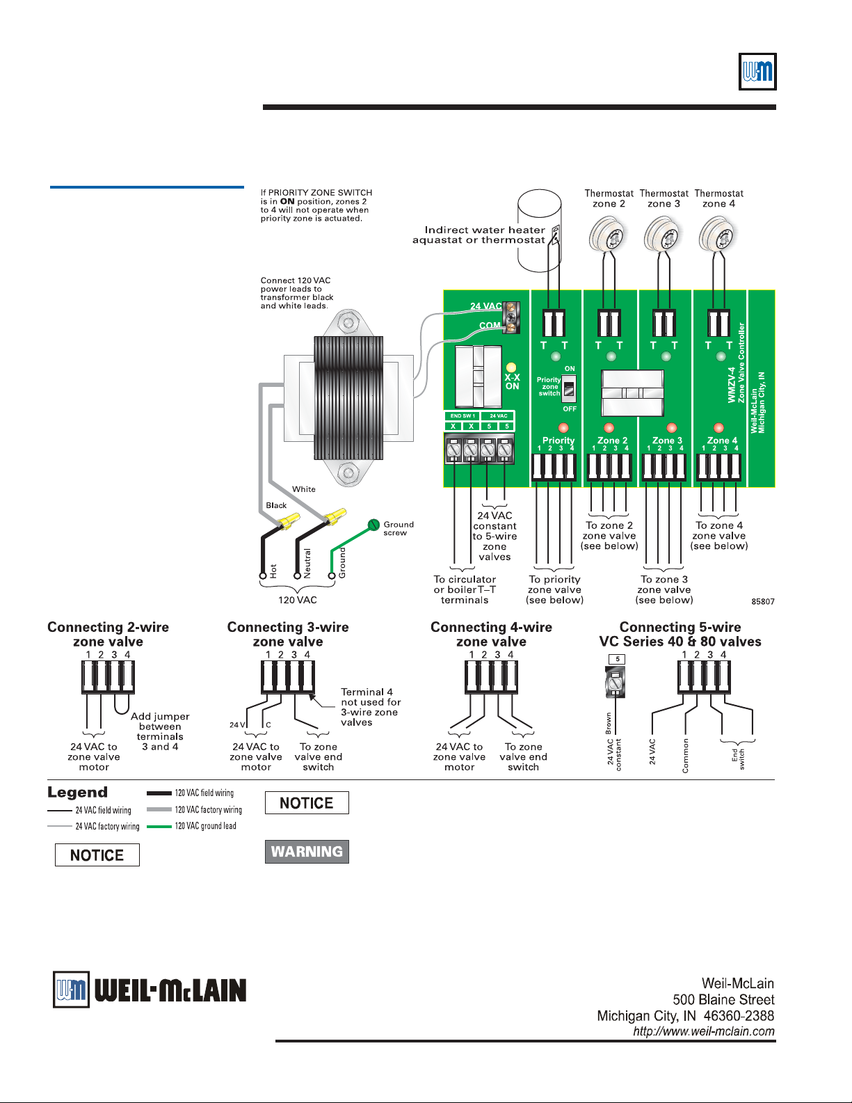
Diagram 1
Typical WMZV-4
Sequence of operation:
• When a zone thermostat closes,
the WMZV-4 activates its zone
valve. The green light for the zone
comes on.
• When the zone valve end switch
closes, it causes the red light to
come on, indicating the zone
valve is fully open.
• The WMZV-4 then activates the
end switch relay and turns on the
yellow light to indicate the isolated
contacts are now closed. This
allows the boiler or circulator to
operate device(s) wired to X-X.
• If the PRIORITY ZONE
SWITCH is in the ON position,
the WMZV-4 will not activate
zones 2, 3 or 4 while the priority
zone calls for heat.
All wiring must be installed in accordance with:
U.S.A. — National Electrical Code and any other national, state or local code
requirements. Wiring must be N.E.C. Class 1.
Canada — C.S.A. C22.1 Canadian Electrical Code Part 1 and any other
national, provincial or local code requirements. Wiring must be C.S.A.
C22.1 C.E.C. Part 1.
Electrical shock hazard — Disconnect power before installing or servicing.
Can cause severe personal injury, death or substantial property damage if
ignored.
This controller will NOT function with White-Rodgers 1311 and 1361 zone
valves.
Install all zone valves per valve
manufacturer’s instructions.