Loading ...
Loading ...
Loading ...
8
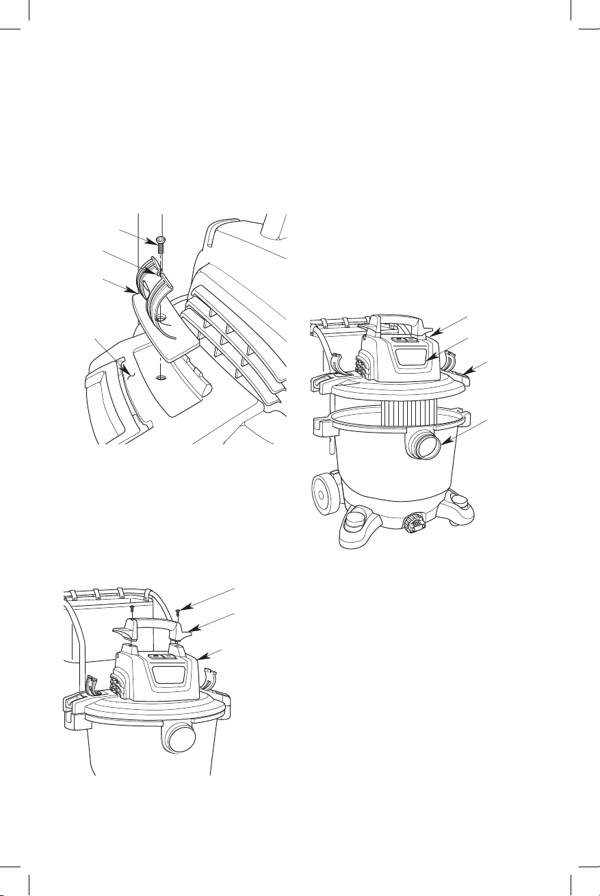
Fig. K
Hose Clips Assembly (Fig. K)
1. Align the Hose Clips in the recessed areas on the
Powerhead Assembly.
2. Insert Screw and tighten to fasten the Hose Clips to the
Powerhead Assembly.
NOTE: The Hose Clip has a Screwdriver Notch for ease of
assembly.
Powerhead Assembly (Fig. M)
1. Line up front (label side) of Powerhead Assembly with
Vac Inlet Port, located on the front of the Drum.
NOTE: Powerhead Assembly must be aligned with Drum
for proper attachment.
2. Place Powerhead Assembly on top of Drum.
3. Be sure Powerhead Assembly completely covers the
top of the Drum so leakage does not occur.
4. Press down on the Powerhead Latches to securely
attach the Powerhead Assembly to the Drum.
5. To remove the Powerhead Assembly, first unplug
the unit from the electrical outlet. Then lift up on the
Powerhead Assembly Latches and remove from Drum.
Fig. M
Hose
Clip
Powerhead
Assembly
Notch
Screw
Fig. L
Carry Handle Assembly (Fig. L)
1. Place the Carry Handle on the Wet/Dry Vac Powerhead
Assembly.
2. Tighten Two Screws to assemble the Carry Handle on
the Powerhead Assembly.
Screws
Carry
Handle
Powerhead
Assembly
Powerhead
Assembly
Lid
Latches
Vac
Inlet
Label
Loading ...
Loading ...
Loading ...