
iSpring Reverse Osmosis Water Filtration
Systems
INSTALLATION INSTRUCTIONS
& OWNER’S MANUAL
Ver. 11/2018
Copyright ©2005-2017 ISPRING WATER SYSTEMS, LLC. All rights reserved.

Page 1www.123filter.com | (678) 261-7611 | Support@123Filter.com
We stand behind our products
iSpring has been dedicated to providing high quality drinking water to families across the United
States since 2005.
From various residential water filtration systems that purify your water in everyday life, to drinking
water faucets that deliver pure, healthy, and tasty water to you and your family, iSpring strives for
high standard products and aims to make excellent drinking water accessible for all households.
At iSpring, we strive for high standard products and aim to make excellent drinking water
accessible for all households.
With affordable pricing, solid quality, prompt delivery, and top-notch customer service, we hope to
assist in bringing you great water for years to come.

Page 2www.123filter.com | (678) 261-7611 | Support@123Filter.com
Table of Contents
System Installation
Prior to Installation ................................................................................................. 3
Component Identification ....................................................................................... 4
Installation Tips ...................................................................................................... 5
Installation Steps ..................................................................................................... 7
Step 1: Installing the Feed Water Adapter ............................................................. 7
Step 2: Installing the RO Faucet ............................................................................. 8
Step 3: Installing the Drain Saddle ......................................................................... 8
Step 4: Installing the Vertical Filters: Stages 1, 2, and 3 ....................................... 9
Step 5: Installing theTank Shut-Off Valve ............................................................. 9
Step 6: Installing the Reverse Osmosis Membrane ................................................ 9
Step 7: Tubing Hook Up ....................................................................................... 10
Step 8: System Start Up ........................................................................................ 12
Leak Stop Valve Installation ................................................................................ 13
Owner's Manual
Section 1: iSpring RO System Maintenance ........................................................ 14
Section 2: Knowledge Base and FAQ .................................................................. 17
Section 3: Troubleshooting Guide for Newly Installed Systems ......................... 21
Section 4: Glossary and Terms to Know .............................................................. 23
Warranty
Warranty Registration ........................................................................................... 26

Page 3www.123filter.com | (678) 261-7611 | Support@123Filter.com
System Installation
Prior to Installation
Inspect the package
Open the box and remove all of the components. Inspect them to ensure nothing was damaged
during shipping. If any part is cracked or broken, please immediately contact iSpring Customer
Support for a replacement. Identify and get familiar with the components.
Recommended tools list
● Variable speed drill with two bits: ¼” (for drilling a hole on PVC drain pipe), ½” hollow
diamond (for drilling a hole on countertop for drinking faucet)
● 5/8”, 9/16” open-end wrench, or adjustable wrench, pliers
● Phillips head screwdriver
● Scissors or utility knife
Operating conditions
● Minimum water pressure: 45 PSI, otherwise a booster pump is necessary to raise the
incoming water pressure and improve the RO efficiency.
● Maximum water pressure: 70 PSI, otherwise a pressure regulator (part no. APR70) is
required to lower the PSI to the maximum level.
● Operating water temperature range: 40 – 100 °F (4 - 37 °C) (This RO system is NOT
designed for HOT water). The RO process will be slightly faster the warmer the source
water is and vice versa.
● Maximum TDS: 750 ppm
● Install this RO system in a location where it is safe from hot/cold weather and direct
sunlight. Avoid hitting, dropping, or dragging the system as this can cause cracks and leaks.
Page 4www.123filter.com | (678) 261-7611 | Support@123Filter.com
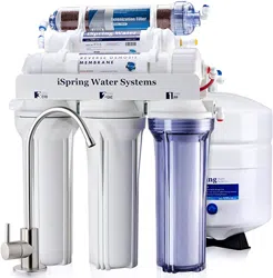
Component Identification
RO Machine Head
* (membrane not yet installed)
RO Membrane
3 Pre-Filter Housings and
Cartridges
Storage Tank
RO Faucet w/ Installation Kit
Feed Water Adapter
4-Color Tubing Set
Drain Saddle ¼”
Tank Valve
Housing Wrenches
Leak Stop Valve
Spare O-Rings and Fittings
(Real package quantity may
vary)
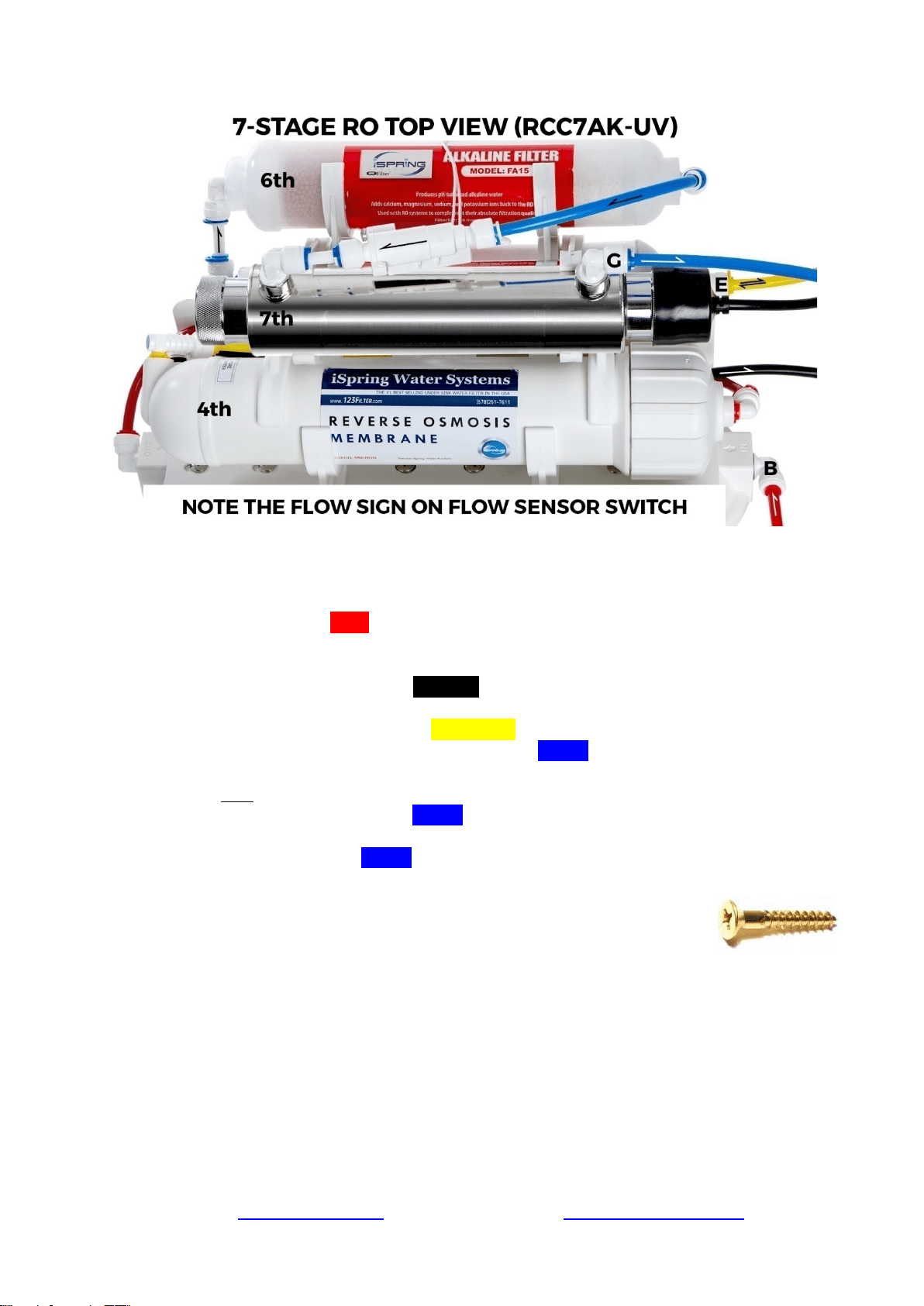
* If your system is a 6-stage or 7-stage system with an Alkaline, DI, and / or UV filter, the 6
th
and
7
th
stages are already pre-installed on the machine head. The UV filter is typically the final stage for
all RO UV systems, but can be moved in front of the 1
st
stage if the incoming water is already clear.
Page 5www.123filter.com | (678) 261-7611 | Support@123Filter.com
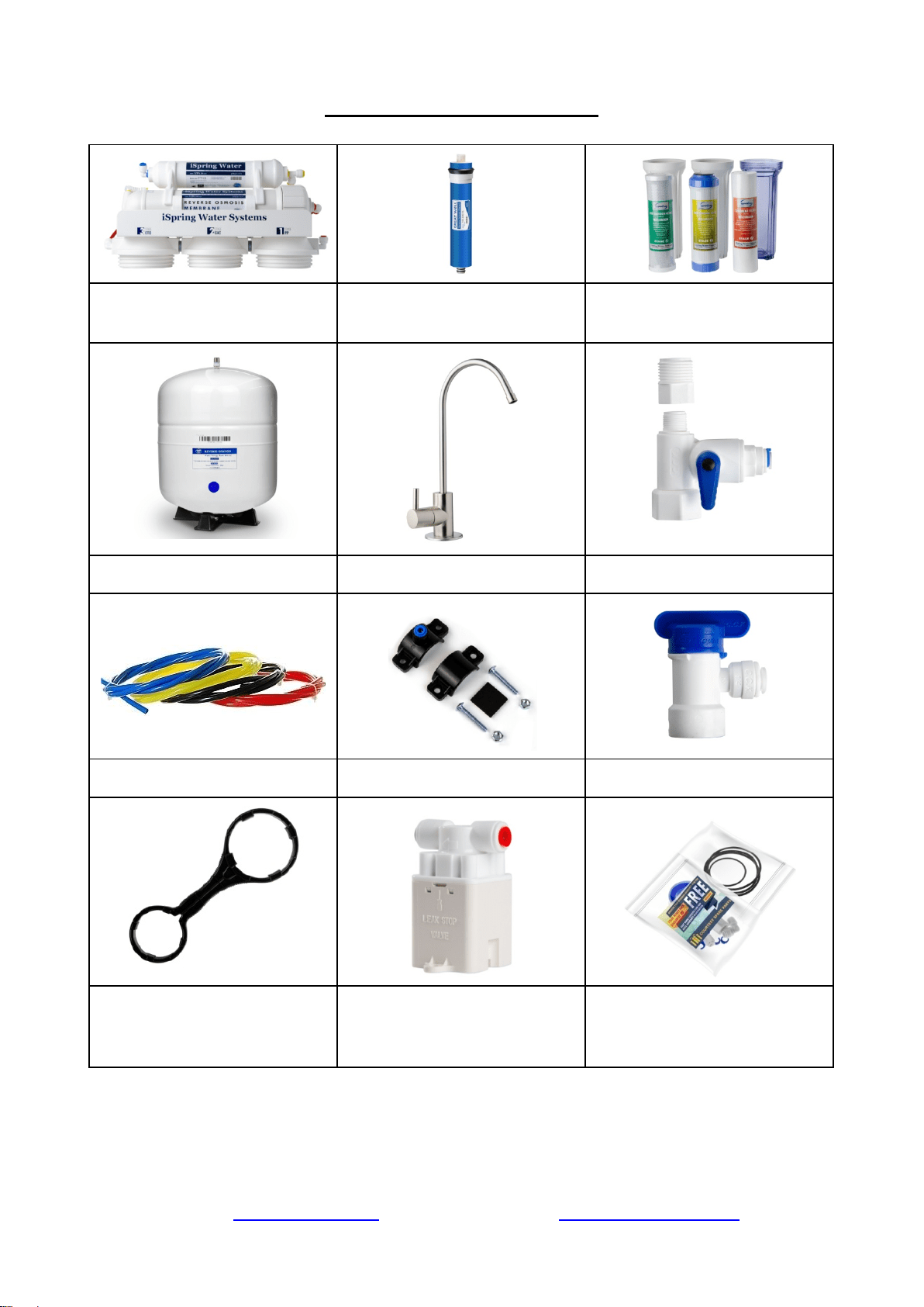
Installation Tips
How to use the Quick-Connect fittings
Figure 1
To connect:
1. See Figure 1. Check and cut the tubing end squarely and cleanly with utility knife or
scissors.
2. Make a ⅝” mark at the end of the tube so you will be able to confirm when the tube is
inserted fully into the fitting.
3. Remove the blue lock clip from the fitting with your nail. If the lock sleeve pops out of the
fitting when doing this, simply pop it back in.
4. Insert the tube into the fitting until you reach the ⅝” mark on the tube. You will feel
resistance when the tube reaches the small rubber O ring inside the fitting. You will need to
wiggle the tube and apply additional pressure to get it passed this O ring and create the seal.
If the tube is not ⅝” into the fitting and past the O ring, no seal will be created and
leaking will occur.
5. Once the tube is fully inserted into the fitting, pop the blue lock clip back on the fitting. This
will lock the tube in place and prevent it from moving.
Figure 2
Figure 3
Page 6www.123filter.com | (678) 261-7611 | Support@123Filter.com
To disconnect:
1. See Figures 2 and 3. Remove the blue lock clip from the fitting.
2. With the blue lock clip removed, use your thumb and index finger to hold down the lock
sleeve. This will release the metal teeth holding the tube in place. While holding the lock
sleeve down with that hand, use your other hand to remove the tube from the fitting.
How to drill a ½” hole in your sink or counter-top
1. It’s highly recommended to watch the YouTube video “How To Drill Faucet Holes” to
get a better understanding of the process. Depending on what kind of countertop you have,
you may want to hire an experienced professional to ensure the hole is drilled correctly.
2. Choose a half inch Diamond Core Bit for granite, and a titanium drill bit for steel. Do NOT
use a hammer drill on nature stone, glass, and ceramic.
3. An indent should be made with a punch on steel before drilling to help guide the bit.
4. Use caution when drilling on a Porcelain sink, as it could be easily chipped. Set drill speed
on slow. Press the bit downward firmly until breaking through the slippery surface. Some
people found it is easier to secure the bit by drilling through a piece of wood that is firmly
pressed on the surface.
5. Use coolant to disperse heat. Choose water for granite, and oil for steel. Use the Water
Suction Cup to hold coolant inside and prevent the drill bit from slipping.
6. Starting at slowest speed, hold the drill firmly and vertically and prevent the drill bit from
slipping on the counter.
7. Once breaking through the smooth surface, swirl the drill a little to apply pressure in a circle
evenly.
8. Be patient and deliberate. It can take 20 – 40 minutes to drill through one inch.
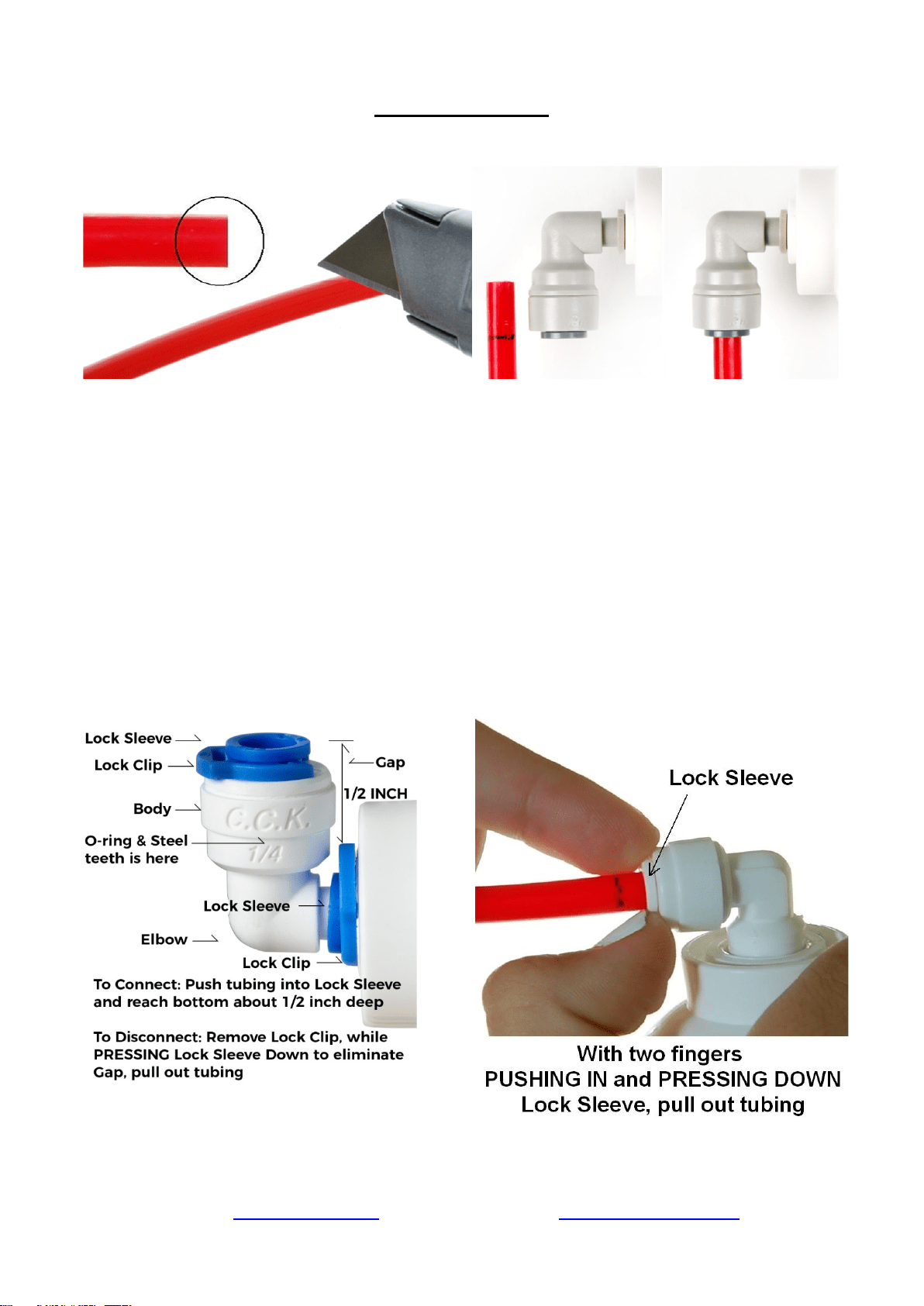
Sample Installation
Figure 4
Page 7www.123filter.com | (678) 261-7611 | Support@123Filter.com
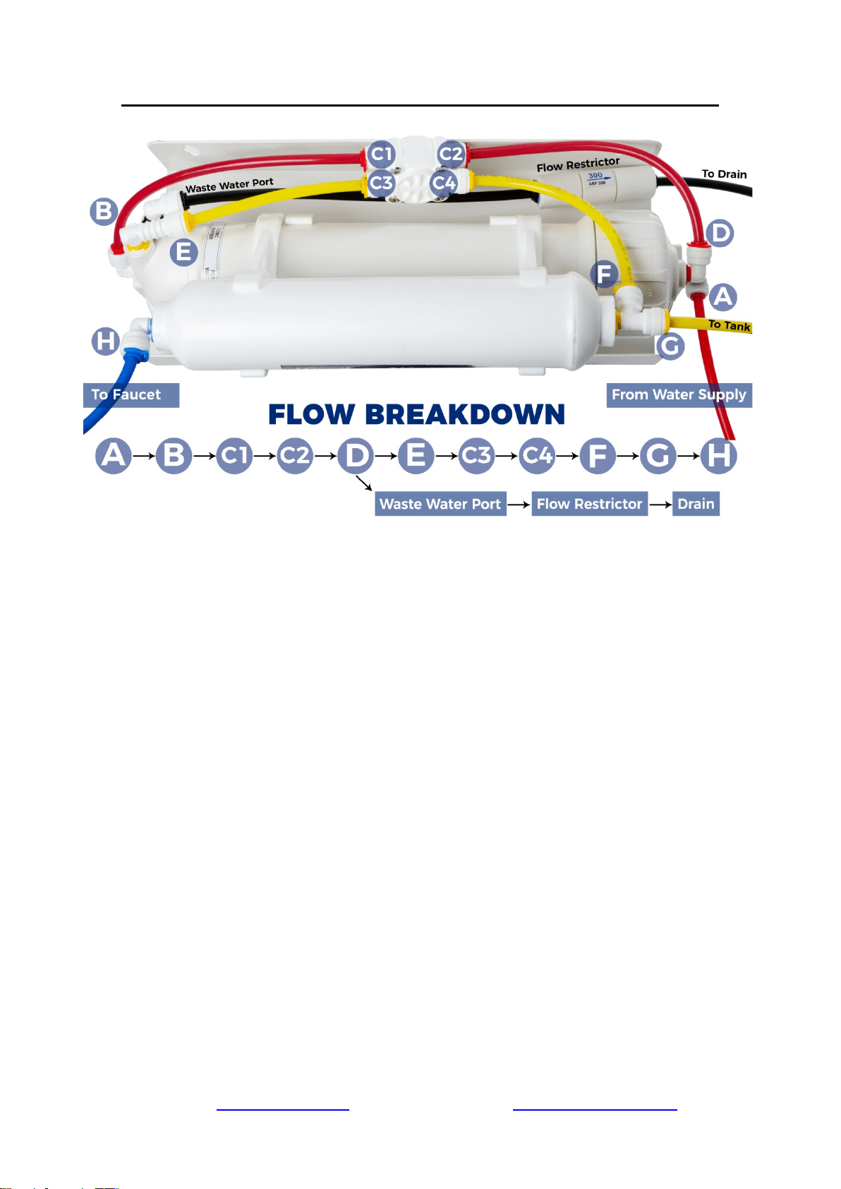
A. Source water from Feed Water Adapter → B. Source water to 1st stage water inlet
C. Waste water from Flow Restrictor →D. Waste water to Drain Saddle/drain pipe
E. RO water from stage 5 “T” fitting → F. RO water to Storage Tank
F. When the drinking faucet is opened, RO water from the tank passes through E and G → H. RO
water to the drinking faucet
Installation Steps
Before you begin the installation, it is highly recommended that you watch the
video “iSpring Reverse Osmosis Installation” on YouTube.
Note: If you plan on mounting/hanging the system, it is highly recommended to
include supports under each of the bottom three housings. Supports under the
housings will take the water weight off the housing threads, and ensure the thread strength does not
decay over the years.
Note: Steps 1 – 7 are independent, and can be performed in any order.
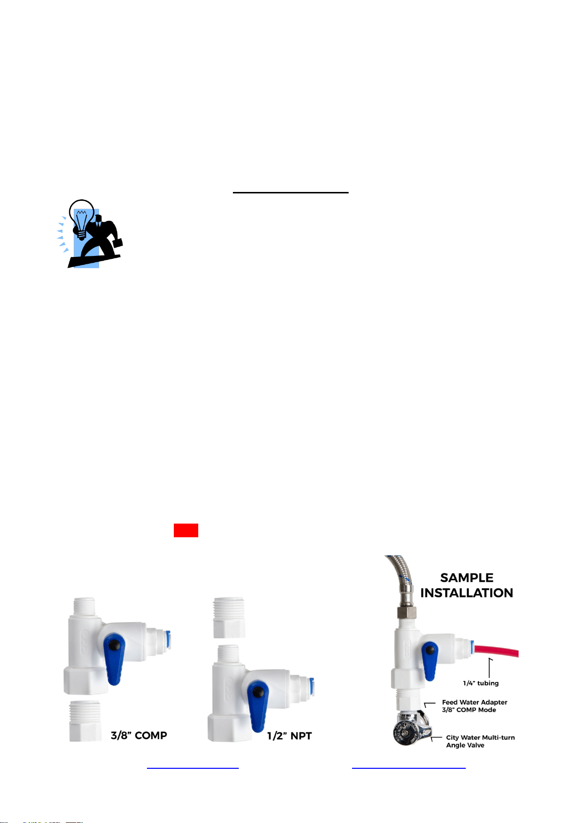
Step 1: Installing the Feed Water Adapter
(The bushing can convert 3/8” comp. to ½” NPT.)
1.1 Turn off the Cold Water Line via the Cold Water Supply Valve (CWSV) under the sink.
Open the kitchen faucet to release any pressure and make sure the water has stopped before
proceeding to the next step. Get a towel or bucket to catch any water drips. Disconnect the
Kitchen Faucet Connector (KFC) pipe from the CWSV.
1.2 Check to make sure the O-ring is seated inside the Feed Water Adapter female end, and
twist it onto the CWSV. Tighten it using a wrench or pliers.
1.3 Twist the KFC onto the male end of the Feed Water Adapter. Turn the handle of the Feed
Water Adapter to the perpendicular OFF position. Turn on the CWSV slowly, and ensure
you are getting a proper seal.
1.4 Connect the 1/4” RED tubing to the Feed Water Adapter.
Feed Water Adapter with Bushing to convert
3/8” COMP to 1/2” NPT
Page 8www.123filter.com | (678) 261-7611 | Support@123Filter.com
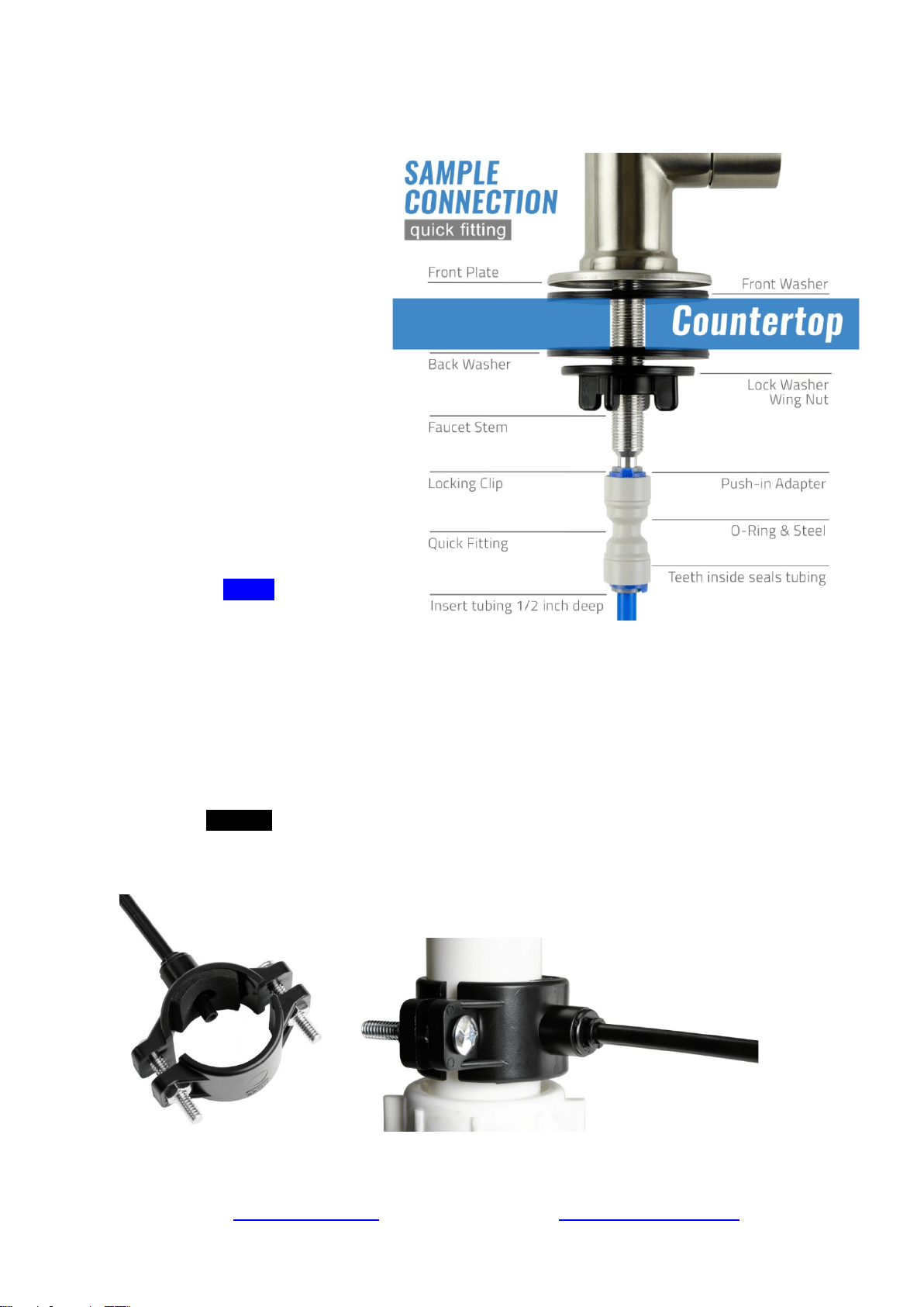
Step 2: Installing the RO Faucet
2.1 If your kitchen sink does not
have an existing ½” faucet
hole, you will have to drill one.
(Refer to How to drill a Hole
on Sink or Counter-top). Wipe
clean and dry the area.
2.2 Slip the front plate on the
faucet stem, followed by the
rubber washer. Insert the
faucet stem into the hole on
the countertop. Under the sink,
slip on the back rubber washer,
and tighten the nut with the
plastic wing.
2.3
Slide the quick connecting up
the push-in adapter on the
base so that it seats securely
into the faucet stem, then lock
it in place by sliding the blue
clip under the collet.
2.5 Insert the BLUE tubing about
1/2 inch into the push-in
fitting,
and again, secure it with the
blue clip.
Step 3: Installing the Drain Saddle
3.1 Choose a spot on the drain pipe that is convenient for installing the drain saddle and tubing.
A horizontal pipe is recommended to minimize the dripping sound.
3.2 Drill a 1 /4” hole in the drain pipe, and paste the black sticky pad around the hole.
3.3 Cut the BLACK tubing end to make a 45 degree angle. Insert the tubing into the 1/4” hole
in the drain pipe, install the back plate, and tighten the two screws with hex nuts while the
tubing remains in the hole.
3.4 Insert Lock Clip. Pull the tubing lightly to make sure it is secure.
Page 9www.123filter.com | (678) 261-7611 | Support@123Filter.com
Step 4: Installing the Vertical Filters: Stages 1, 2, and 3
4.1 Make sure the O-ring is seated inside the groove on
top of the filter housing. A light amount of food-
grade silicon jelly may be used to help the O-ring
seal better, but is not required.
4.2 The filter cartridges are preserved in shrink wrap.
Note the direction sign on the sticker before
removing the wrap.
4.3 When placing the filter cartridge into its housing,
make sure it is centered and the knob protruding
from the bottom of the housing fits in the central
hole of the filter.
4.4 Screw the housing, with filters attached, onto the
housing caps (caps are pre-assembled on the
machine head). The cap also has a center knob
which should be inserted into the center hole of the
filter cartridge. Twist the housing on in a clockwise direction by hand, and then use the
housing wrench to tighten it another 1/4 – 1/2 of a turn. Do not over tighten. This can
cause leaks and make it difficult to unscrew the housing when replacing filters.
4.5 Follow steps 1.1 – 1.4 to install the GAC and CTO filters. *Note* the second stage GAC is
the only filter that must go in a certain direction. Make sure the end with the rubber washer
faces up, thereby attaching it to the housing cap.
Step 5: Installing the Tank Shut-Off Valve (TSV)
5.1 Wrap 10 - 15 wraps of Teflon tape clockwise (when looking from above) onto the metal
thread at the top of the tank.
5.2 Screw (clockwise) the Tank Shut-off Valve on and tighten it by hand. Do not over tighten.
5.3 Connect the YELLOW tubing into the Quick-Fitting on the TSV.
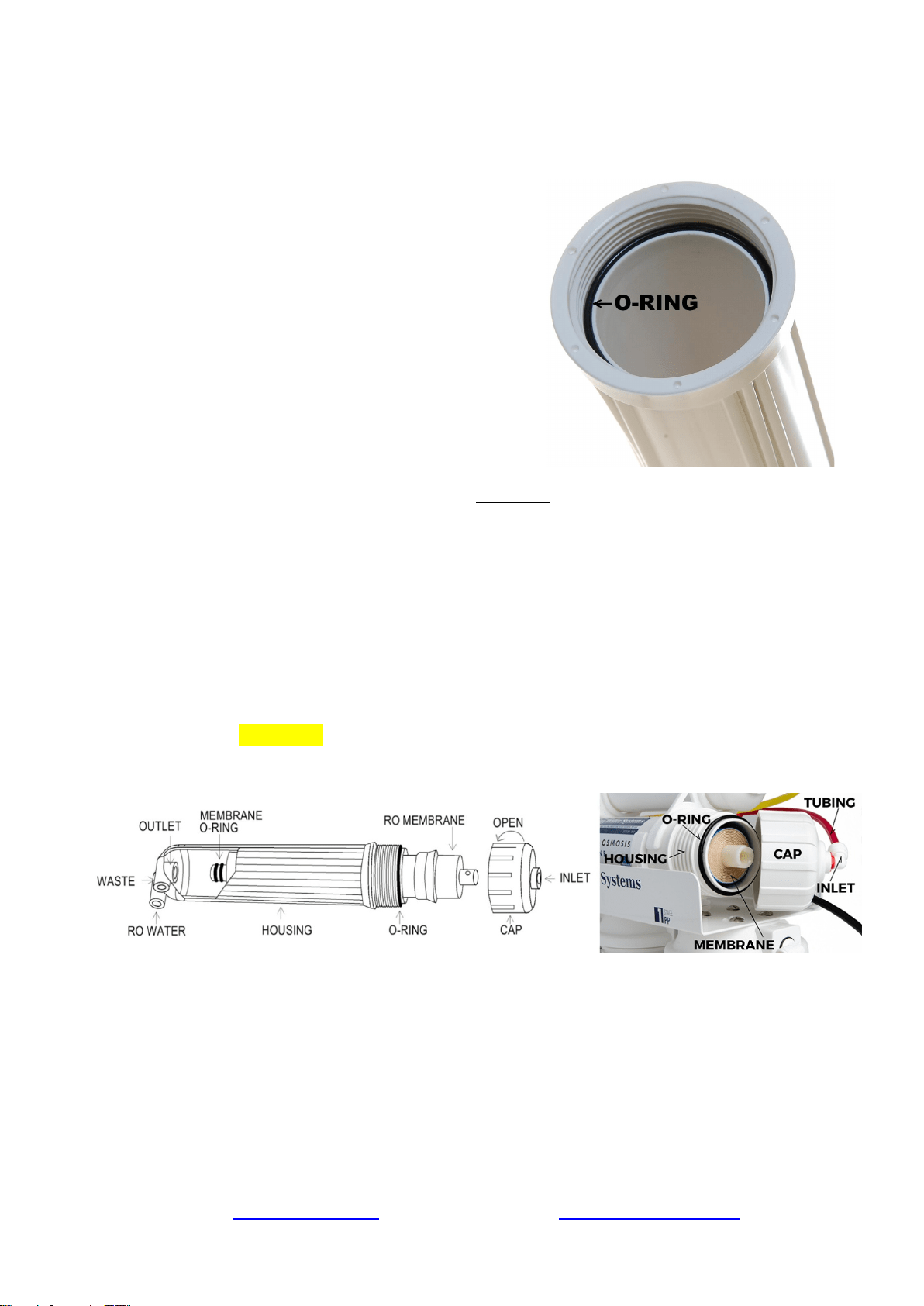
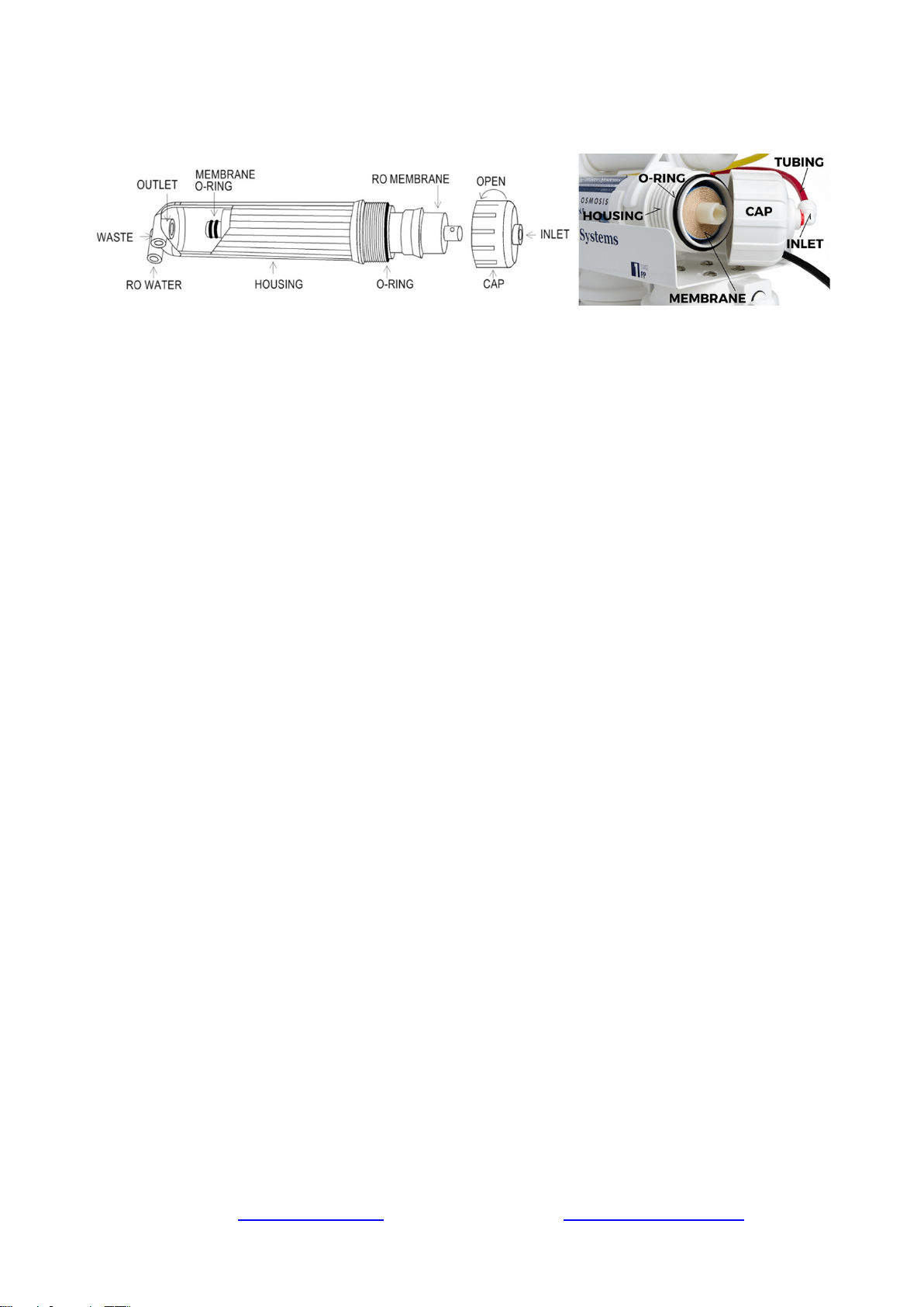
Step 6: Installing the Reverse Osmosis Membrane
Figure 8 Figure 9
6.1 First, disconnect the white tube from the quick-fitting connection on the membrane cap.
This will allow you to unscrew the membrane housing cap.
6.2 All the systems are wet tested without filters prior to shipment, so you may notice some
water drops still inside the housing.
6.3 Unscrew (counter clockwise) and remove the membrane cap.
6.4 Note: Following the flow direction sign on the membrane, cut open the “small end” of the
bag, hold the membrane with the bag to avoid touching or contaminating it, and firmly
insert it into the housing. This way the end with the two small black O-rings towards the
bottom. When it is inserted fully and properly, the “bigger” end of the membrane will be
Page 10www.123filter.com | (678) 261-7611 | Support@123Filter.com
even with the housing opening. See Figure 8-9. After the membrane has been fully inserted
you may then disregard the bag.
6.5 Before twisting the housing cap back on, make sure the O-ring is seated at the end of the
membrane housing as shown in figures 8 and 9. This is very important to avoid leaking
and damage to the O-ring.
6.6 Place the membrane housing cap back on and hand tighten it, then use the housing wrench
to tighten it another ¼-½” of a turn. Do not over tighten.
6.7 DO NOT reconnect the tubing to the fitting on the cap at this point (will be done in system
start up).
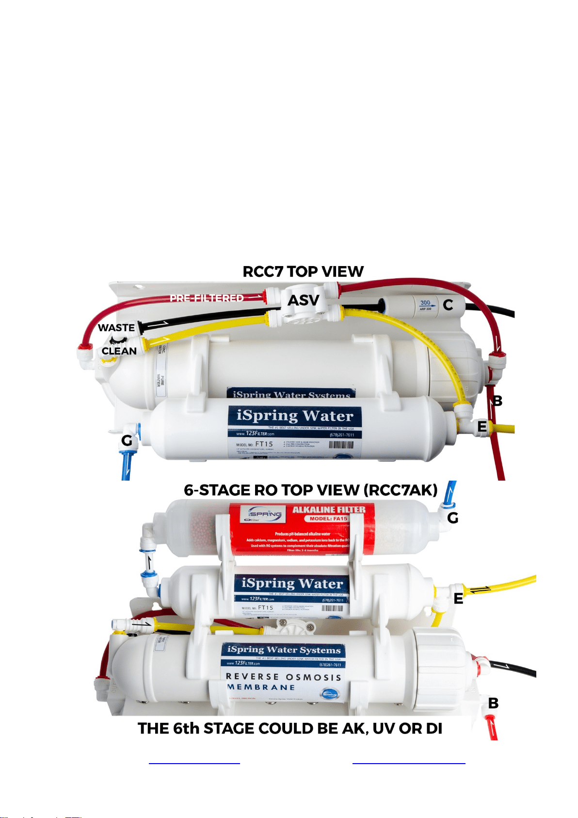
Step 7: Tubing Hook Up (model specific sub-steps are marked with *)
7.1 See figure Sample Installationand figures of system top view, and note connection points A-
B, C-D, E-F, and G-H.
Page 11www.123filter.com | (678) 261-7611 | Support@123Filter.com
7.2 Facing the front of the system, the 1st stage is the see through housing located on the right
hand side. Connect the RED tubing Feed Water Adapter (point A) to the stage 1 elbow
fitting (point B).
7.3 Connect the Flow Restrictor (point C, 3-inch long cylinder with a FLOW labeled on it) to
the Drain Saddle (point D) with the BLACK tubing.
7.4 On the right side of the Post Carbon Filter (FT15, 5
th
stage), connect the T-fitting (point E)
and the Tank Valve (point F) with the YELLOW tubing.
7.5 At the left end of the stage 5 FT15 filter, insert the BLUE tubing (links to RO faucet) into
the elbow fitting.
* Models with UV/AK/DI: RO water flows out of point G at FT15 and flows into the input
(left) side of the next stage. So the BLUE tubing should be connected to the output side of
the final stage.
7.6 Connect the other end of the BLUE tubing to the RO faucet.
7.7 You may neatly organize the tubings, but make sure to leave enough length so the filter
system can be moved freely in and out of the cabinet when replacing
filters.
7.8 You can mount the system using two 10 x 1-1/4 Phillips Flat Wood
Screws. This will make replacing filter cartridges easier.
Note: If you plan on mounting/hanging the system, it is highly recommended to include
supports under each of the bottom three housings. Supports under the housings will take the
water weight off the housing threads, and ensure the thread strength does not decay over the
years.

Page 12www.123filter.com | (678) 261-7611 | Support@123Filter.com
Step 8: System Start Up (model specific sub-steps are marked with a *)
* If your model has a UV stage, do not plug in the power until the system has been fully flushed
8.1 Make sure no tubings are kinked. Turn the Tank Shut-off Valve OFF (perpendicular to the
yellow tube). Place a towel under the system to catch any possible water leaks.
8.2 To prevent any residual carbon from the carbon pre filters from getting into the RO membrane, you
previously left the tubing to the inlet of the RO membrane housing cap disconnected. Open the
Feed Water Adapter Valve and Cold Water Supply Valve (CWSV), and flush the first three stages
into a bucket until the water turns clear.
8.3 Once the water is clear, shut off the Feed Water Adapter and re-connect the tubing to the RO
membrane housing cap. You will want to flush the system like this whenever the first three stages
are changed.
8.4 Open the RO faucet. Slowly open the Feed Water Adapter back up and check for any leaks.
The top 3 causes of leaks are 1) The tubing is not fully inserted into the quick-connect fitting. 2)
The O-ring is not in the correct place or is kinked. 3) The Housing/Cap is not tightened properly or
misaligned with the threads.
8.5 Within 5 minutes, RO water will start slowly trickling from the faucet. Let the faucet trickle for at
least 15 minutes to flush out the entire system apart from the tank. The water may appear black due
to loose carbon from new carbon filters. It will eventually turn clear apart from many tiny air
bubbles leaving the system.
8.6 Shut off the RO Drinking Faucet. Turn on the Tank Shut-off Valve. Wait for the tank to fill up
completely. It will take 1.5 to 2.5 hours depending on your water temperature (40F-100F, the
warmer the faster), water TDS (up to 750, the lower the faster), and incoming water psi (45-70, the
higher the faster).
8.7 After the tank is full, open the RO Drinking Faucet to drain the tank completely. Do not use the
first tank of water. Let it drain into the sink until the stream turns back to a trickle - this means the
tank has emptied and you can close the RO faucet to let it begin filling again.
8.8 * If your system has a UV filter, plug in the UV power and check to make sure the UV light is
turning on when water flows through it. The UV filter has a Flow Sensor Switch that detects water
flow and only turns the light on when needed. If the UV is not turning on when water flows through,
confirm the power source you are using has power. Typically the garbage disposal outlet only has
power when the disposal is switched on.
8.9 The TDS (total dissolved solids) of the water should be tested periodically to verify that the system
is performing properly.
8.10 Check for leaks daily for the first two weeks after installation to ensure the system is functioning
properly. Install the included Flood Alarm to provide additional peace of mind and protection.
Page 13www.123filter.com | (678) 261-7611 | Support@123Filter.com
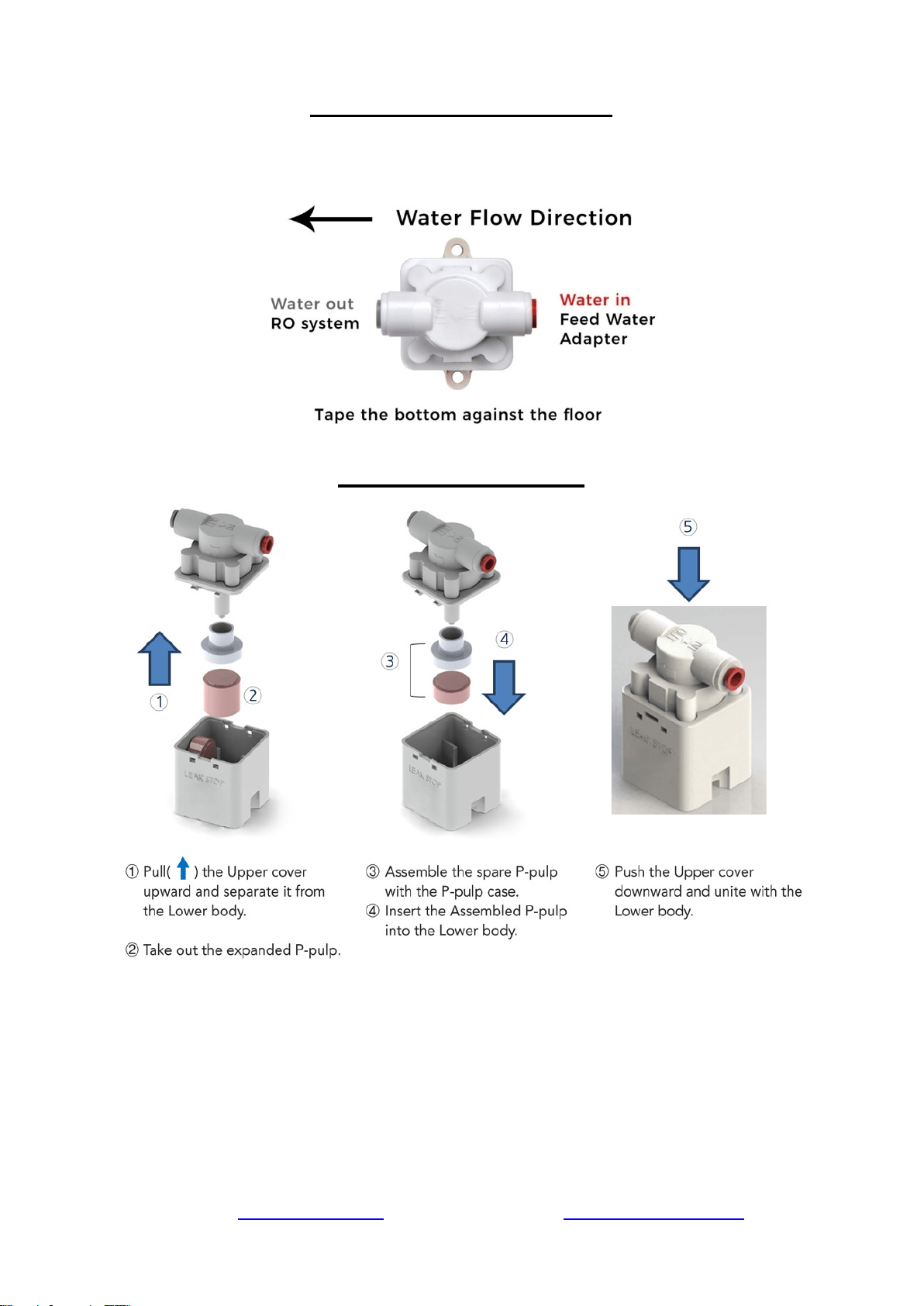
Leak Stop Valve Installation
The Leak Stop Valve is a reusable mechanical leakage protector. When the pulp detects water
leakage, it will expand and shut down the feed water. Before connecting the tubing into the fitting,
make sure the end of the tubing is cut square and not damaged or scratched.
Replace expanded pulp
Congratulations, you have successfully installed your
iSpring Reverse Osmosis Water Filtration System!
Start enjoying fantastic reverse osmosis water right from your tap!
------------------------------------- End of Installation Section ------------------------------------
Page 14www.123filter.com | (678) 261-7611 | Support@123Filter.com
OWNER’S MANUAL
Please read this manual for useful reverse osmosis system maintenance information.
Section 1: iSpring RO System Maintenance
All iSpring RO systems are designed with ease of use and low maintenance in mind. If the filter
cartridges are changed on schedule as suggested, the system will work properly for years to come.
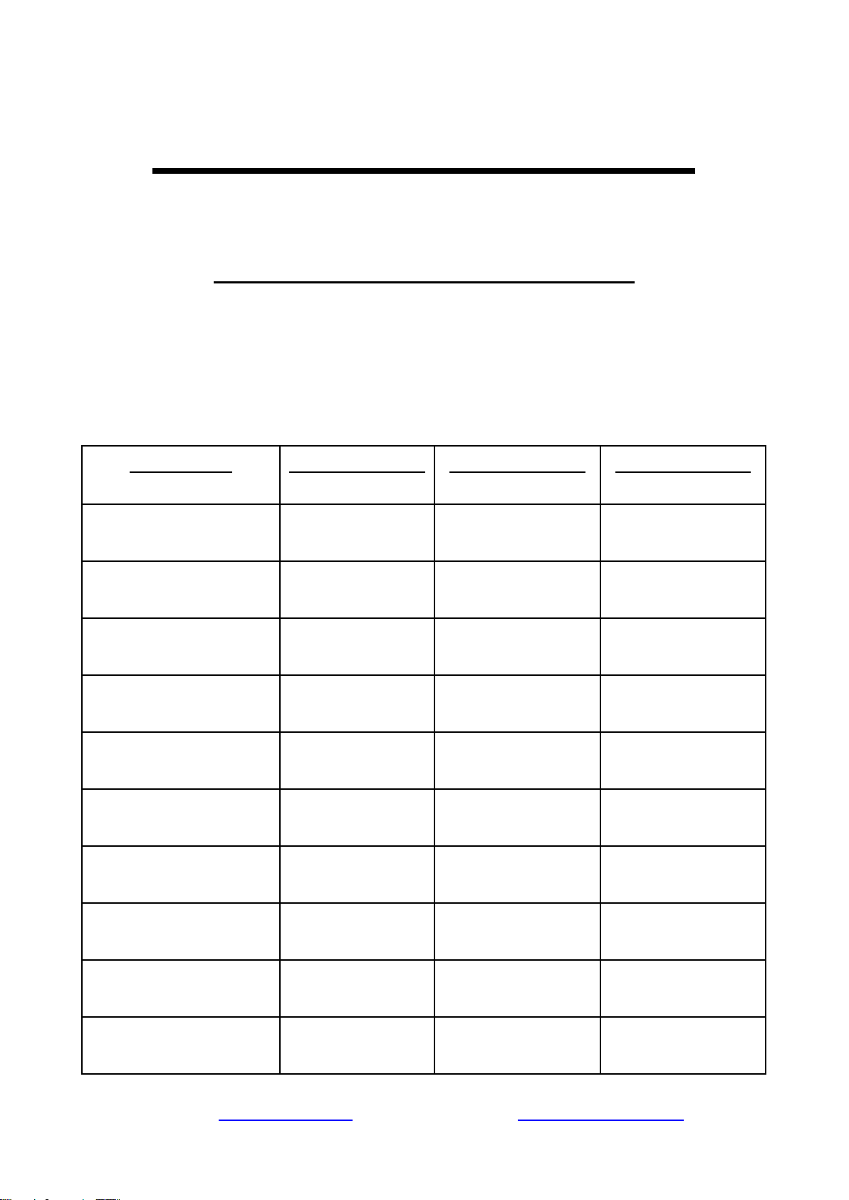
See the chart below for the filter pack model numbers for your system. The filter packs can be
found on 123filter.com, Amazon, or HomeDepot.com.
System Model
1-Year Filter Pack
2-Year Filter Pack
3-Year Filter Pack
RCC7, RCC7P
F7-GAC
F15-75
F22-75
RCC7AK, RCC7P-AK
F9K
F19K75
F28K75
RCC7AK-UV
F10KU
F21KU75
F31KU75
RCC7D
F9D
F19D75
F28D75
RCC7U
F8U
F17U75
F25U75
RCC100P
F7-GAC
F15-100
F22-100
RCC100PAK
F9K
F19K100
F28K100
RCC1UP
F8U
F17U100
F25U100
RCC100UP-AK
F10KU
F21KU100
F31KU100
RCW5
F7-GAC
F15-50
F22-50
Page 15www.123filter.com | (678) 261-7611 | Support@123Filter.com
Note: Stages 6 and/or 7 only exist on certain models.
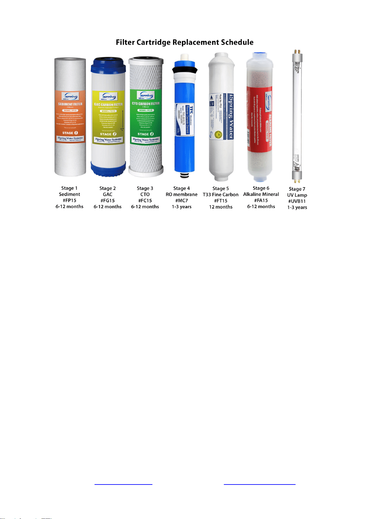
Stage 1 – 3 Pre-Filters
Replace every 6 months or sooner if you notice a decrease in water flow or quality. The
replacement frequency depends on your water usage and source water quality. To protect the RO
membrane from chlorine and other damaging contaminants, it is important to change the pre-filters
according to schedule.
How to change the stage 1 – 3 pre-filters:
1. Shut off the cold water supply valve and tank valve, and open the RO faucet to depressurize
the system. Place a bucket or towel under the system to catch any water spills.
2. If there is enough room under the sink and the filter system is hung on the wall, you can
twist the filter housing off without removing the system from the wall. Otherwise, you will
need to pull the system out, lay it down, and remove the housings at that point. Be careful
with the tubing connections when removing the system.
3. Twist off the filter housings in a counter-clockwise direction using the filter housing wrench.
4. Refer to Installation Step 1.1 to install the new vertical filter cartridges, and tighten the filter
housings back on. Remember not to over tighten them or they will be hard to unscrew next
time.
Stage 4 RO Membrane
Replace every 2-3 years or sooner if the TDS level starts increasing. Check the TDS level at least
once a month to monitor the system’s performance. The TDS rejection rate should be 90%+.To
calculate the rejection rate, divide the RO water TDS into your tap water TDS and subtract from 1.
For example, 20 (RO TDS) / 200 (Tap water TDS) = 0.1 1-0.1 = 0.9 so the TDS rejection rate
would be 90%. (NSF/ASIN STANDARD 58 for RO water filter).
Page 16www.123filter.com | (678) 261-7611 | Support@123Filter.com
How to Change the Reverse Osmosis Membrane
1. The RO membrane typically lasts about 2 – 3 years. The membrane life span depends on the
source water quality, your water usage, and how often the three pre-filters are replaced. To
ensure the system’s performance and water purity, it is important to replace the pre-filter
cartridges on schedule. Use a TDS meter to periodically to check the RO water purity.
2. Shut off the cold water supply valve and tank valve, and open the RO faucet to depressurize
the system. Place a bucket or towel under the system to catch any water spills.
3. Remove the tubing from the quick-connect fitting on the membrane housing cap. Use the
membrane housing wrench to twist off the housing cap in a counter-clockwise direction.
4. Pull out the old membrane. Use scissors or pliers to apply leverage if necessary.
5. Clean the membrane housing using hot water and scent-free dish soap (optional). Rinse
thoroughly.
6. Cut open the small end of the vacuum sealed packaging containing the new RO membrane.
Hold the new membrane through the packaging, and insert it into the housing without
touching the membrane with your bare hands to avoid contamination of the membrane.
7. Make sure the O-ring is properly seated on the end of the membrane housing as shown in
the previous images. We recommend replacing the O-ring every 3 years to prevent leaking
due to an expired or dried out O-ring.
8.
Place the membrane housing cap back on and hand tighten it, then use the housing wrench
to tighten it another ¼-½ of a turn. Do not over tighten.
Stage 5 FT15 Inline Post Carbon Filter and Stage 6 Inline Alkaline Filter*
Replace the FT15 every 12 months and the Alkaline filter every 6 months
1. Remove all quick-connect tubing connections from the FT15 Post Carbon Filter.
2. Unscrew the fittings from both ends of the old Post Carbon Filter. Wrap the thread of each fitting 2-3
times with Teflon tape, and screw them into their respective sides on the new Post Carbon Filter.
3. Reconnect the quick connect tubing connections to the new Post Carbon Filter.
Tank Maintenance
It is recommended to fully empty and refill the tank at least once a month. This keeps the water
inside the tank fresh and not sitting for an extended period of time.
What should I do with the system when going out of town?
When you are leaving for an extended period of time, you will want to shut off the water supply to
the system and empty the tank. To do this, close the knob on the feed water adapter, and open the
faucet until it stops running. This will signify that the tank is empty. If you are going to be gone for
more than a week, you will also want to remove the RO membrane and store it in a damp Ziploc
bag in the refrigerator.
Page 17www.123filter.com | (678) 261-7611 | Support@123Filter.com
Optional Add-Ons
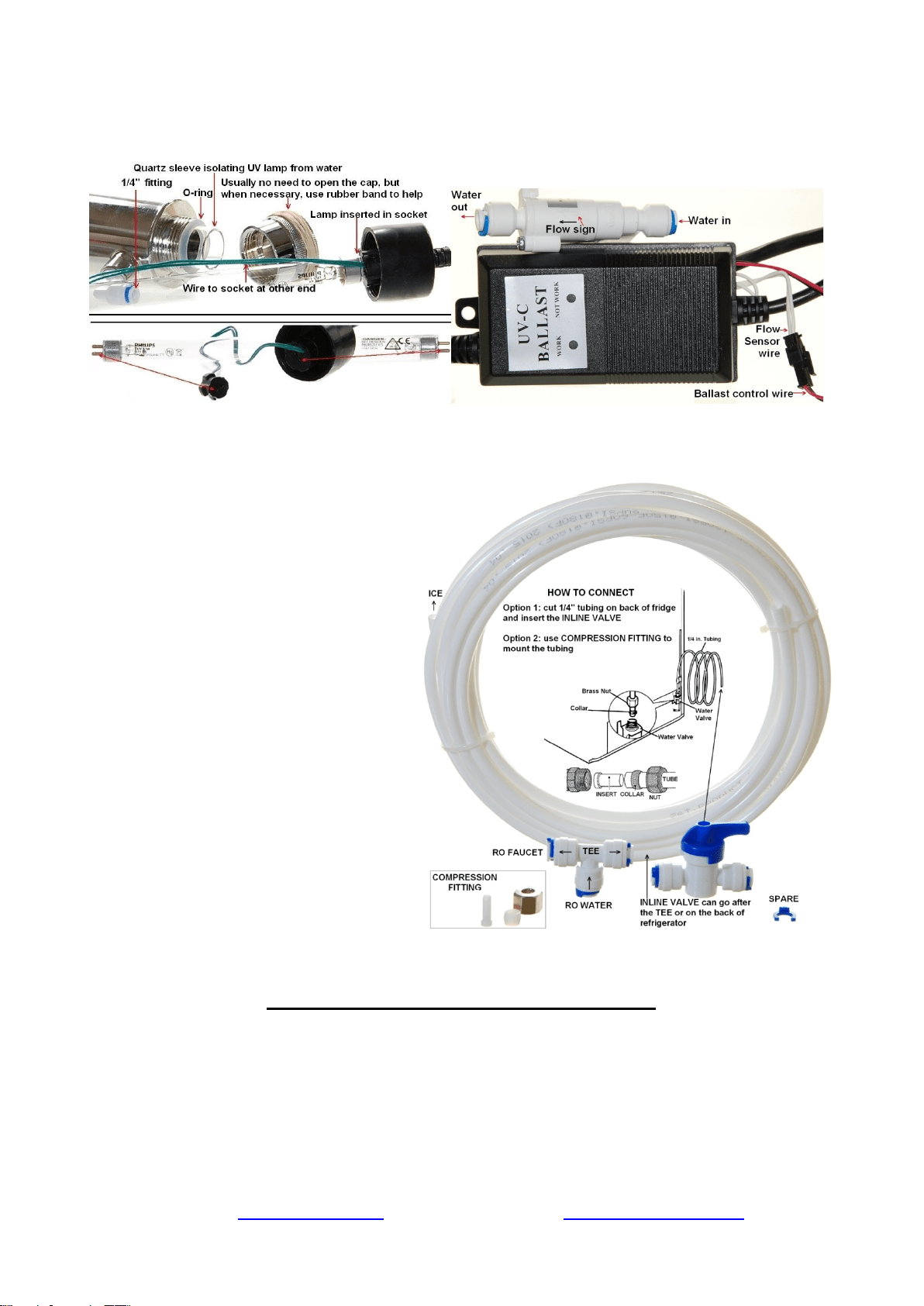
UV Filter (UVF11A)
Figure 13: Flow Sensor Switch for UV Filter
The models with a UV stage have a “U”
in their model number, such as RCC7U,
RCC7AK-UV, RCC1UP-AK, RCC1UP,
etc.
The UV module comes pre-installed on
models with a UV filter. Refer to the
photos above for a better understanding
on how the UV components are
assembled and work together.
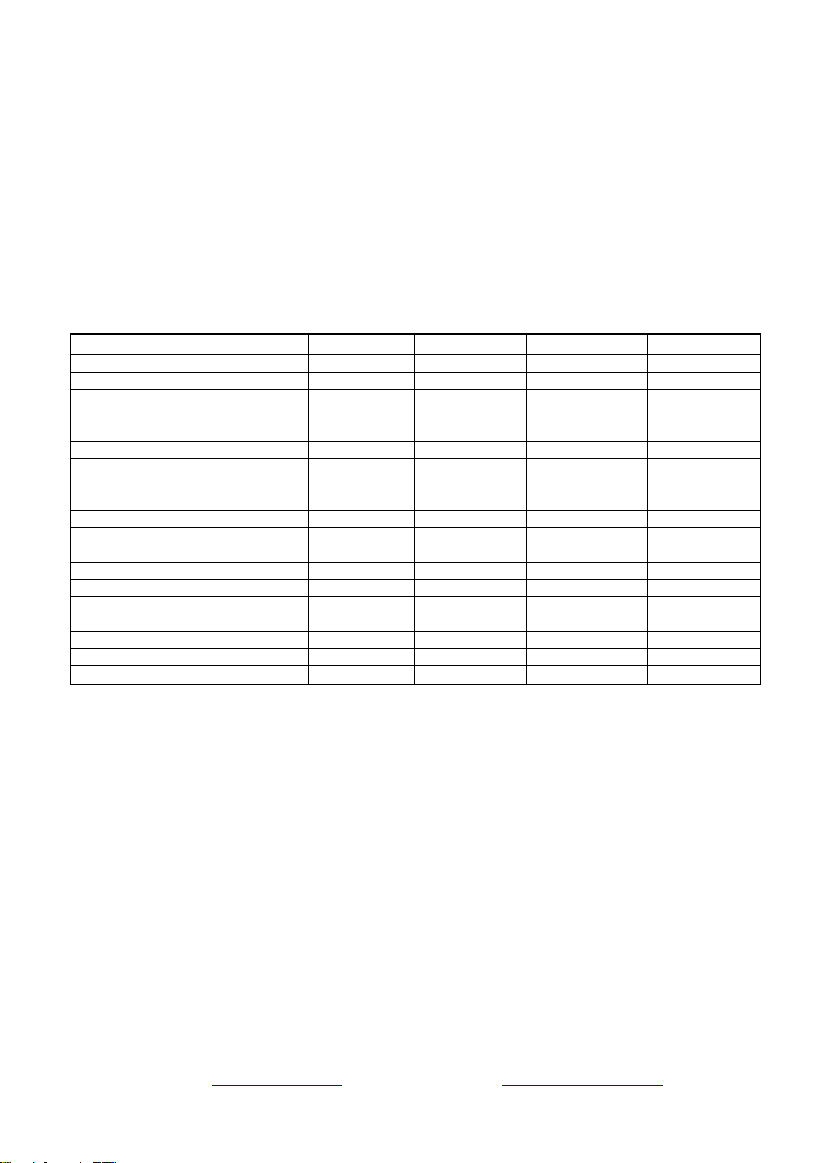
Ice Maker Kit (ICEK)
The Ice Maker Kit (model#: iSpring
ICEK) can be purchased separately to
feed RO water to your refrigerator for
crystal clear ice cubes and great tasting
water. If you choose to hook up the
system to your refrigerator output, it can
take the place of primary output over the
RO faucet.
Section 2: Knowledge Base and FAQ
What Is Reverse Osmosis?
Reverse osmosis, also known as hyper filtration, is a membrane filtration process that separates
undesirable contaminants from water by using pressure to force the water molecules through a
semi-permeable membrane. This process is called "reverse" osmosis because the pressure forces the
water to flow in the reverse direction (from the concentrated solution to the dilute solution) to the
flow direction (from the dilute to the concentrated) in the process of natural osmosis. Reverse
osmosis is used to purify water and remove salts and other impurities in order to improve the color,
Page 18www.123filter.com | (678) 261-7611 | Support@123Filter.com
taste, odor and/or properties of your water. RO filtration can remove up to 99% of most
contaminants including arsenic, nitrates, radium, chromium, fluoride, and dissolved solids such as
sodium, calcium, iron, magnesium, copper, etc.
How Effective Is Reverse Osmosis Filtration?
Reverse osmosis filtration is by far the most effective and economic method of water filtration. It
filters water by squeezing water through a semi-permeable membrane, which is rated at 0.0001
micron (equal to 0.00000004 inch). This is the same technology used to make bottled drinking
water. It is also the most used technology for desalinating seawater, making it into drinking water.
What are the specific contaminants that a reverse osmosis system removes?
iSpring Reverse Osmosis filtration systems reject a wide variety of impurities. Here is a partial list:
Item
Rejection Rate
Item
Rejection Rate
Item
Rejection Rate
Aluminum
97-98%
Ferro cyanide
98-99%
Proteins
90+%
Amoebic Cysts
99%
Fluoride
94-96%
Protozoa
99%
Ammonium
85-95%
Giardia
99%
Pyrogen
99+%
Arsenic
94-96%
Hardness
93-97%
Radioactivity
95-98%
Asbestos
99%
Herbicides
97%
Radium
97%
Bacteria
99+%
Hydrocarbons
90+%
Sediment
99%
Barium
90-98%
Insecticides
97%
Selenium
97%
Bicarbonate
95-96%
Iron
98-99%
Silica
85-90%
Boron
50-70%
Lead
96-98%
Silicate
95-97%
Bromide
93-96%
Magnesium
96-98%
Silver
95-97%
Cadmium
96-98%
Manganese
96-98%
Sodium
92-98%
Calcium
96-98%
Mercury
96-98%
Strontium
90-95%
Chloride
94-95%
Nickel
97-99%
Sulfur/Sulfate
97-98%
Chromate
90-98%
Nitrate
93-96%
Sulphite
96-98%
Chromium
96-98%
PCBs
97%
TDS
95-99%
Copper
97-99%
Pesticides
90+%
THMs
90+%
Cryptosporidium
99%
Phosphate
99+%
Trichloroethylene
90+%
Cyanide
90-95%
Polyphosphate
98-99%
Virus
99+%
Detergents
97%
Potassium
92-97%
Zinc
98-99%
Note: You may or may not have these contaminants in your water. The percentage rejection rate is for reference only.
Percentages may vary since water chemistry varies in each water supply.
What is an Alkaline Filter?
The Alkaline filter changes the acidic RO water into a perfect Natural Alkali Calcium Ionized
Water. The Alkaline filter simply gives back minerals such as ionized calcium, magnesium, sodium,
potassium ion, which were taken away while purifying the water. (Model #FA15)
● Produces pH-balanced alkaline water, helps minimize the fluctuations of your body's pH.
● Turns acidic drinking water into alkali calcium ion water.
● The natural calcium, magnesium, sodium, and potassium ions can be absorbed 100% by the
body.
● These minerals are easily absorbed by the body because they have structurally smaller
molecules which help the body take in more water and replenish lost water quicker.
● Makes the water cleaner and healthier.

Page 19www.123filter.com | (678) 261-7611 | Support@123Filter.com
● Improves the qualities of RO water by adding necessary minerals for proper human
development, such as calcium, magnesium, sodium, potassium, and others readily found in
many natural mineral waters.
● Mainly installed with RO systems to complement their absolute filtration qualities.
What is a DI filter?
DI stands for deionization. The DI filter takes reverse osmosis to a higher level of filtration. It is an
excellent inline filter, especially for those who live in areas with exceptionally high levels of total
dissolved solids (TDS) in their tap water. The DI filter takes the small percentage of contaminants
that the membrane could not remove and filters the water to 99.99% purity, and give you close to 0
ppm TDS. Conductivity attainable less than 0.1uS/cm or resistivity of close to 18 meg ohm. (Model
#FD15)
What is a UV filter?
Our UV filter (model #UVF11A) comes with an 11W UV sterilization lamp in a stainless still
housing. The UV kills 99% of viruses and bacteria in the water. The UV light has wavelengths
between 250 and 270 nanometers (UV-C or UVC band) and is extremely effective in killing many
species of bacteria, mold spores, viruses and other microorganisms. It is recommended for
customers who use well water, rain water, or have bacteria concerns in their water.
What is a TDS meter?
A TDS meter is a handheld Total Dissolved Solids tester. TDS is the total weight of all solids
dissolved in a given volume of water. It is expressed in parts per million (PPM). With a TDS meter,
you can compare the quality of the RO water with your original source water, and also periodically
check the RO water to know when it’s time to change the filters.
Maximum distance from tank to faucet
We recommend staying under a total distance of 15 feet of tubing between the tank and the RO
faucet or output location. The system will produce a faster flow at the faucet with the shortest
tubing run from tank to faucet.
If you wish to go over 15 feet and still get a strong output flow, you may want to consider adding a
demand pump. A demand pump would be installed on the output line, and increase the output water
pressure coming from the tank. We do not offer any, but there are many different models available
on Amazon.
What is the ASOV and what does it do?
The ASOV is the automatic shut-off valve. This valve allows the system to automatically turn off
the water supply using pressure from the pure water side of the system. The ASOV is a critical
piece to the system as it saves water, extends filter life, and improves the performance of the unit.
As the storage tank fills, the tank pressure increases. When the tank fills completely, a pressure
signal is sent to the ASOV, and the water supply to the system is shut off.
Does the UV filter run 24/7? Will the water out of UV filter be hot?
The iSpring UV filter features a Smart Flow Sensor Switch on the tubing connected to the UV
housing. This switch communicates with the UV transformer to turn the UV on and off with water
flow, conserving power and extending the life of the bulb. The UV remains on for an additional
two minutes after flow has stopped to pre-sterilize the water in the system for the next time it is
used. So in short the UV filter only powers on when needed, and does not heat the water up.

Page 20www.123filter.com | (678) 261-7611 | Support@123Filter.com
Can I add an additional filter to my existing system?
Yes, to add an additional filter onto an existing system you will just need the filter itself and a filter
add-on kit. The most common filter to add is the alkaline remineralization filter, which has the
model number “FA15”. The add-on kit comes with elbow fittings, filter clamps, and tubing, and the
model number is “ACL1”.
What is the drain to pure water ratio?
The ratio of drain water to reverse osmosis water is approximately 3:1. This will depend on water
pressure, water temperature, and the contamination level of the water source. A toilet flush uses
about three gallons of water, so on average the daily system drain water is equivalent to an
additional flush of the toilet per day. The drain water is up to twice as contaminated as the tap water
going into the system, as all of the contaminants that the system rejects are concentrated in this
water.
How to check and adjust the tank pressure if needed
When empty, the tank pressure should read between 7 and 10 PSI. The tank bladder comes pre
pressurized, so there is no need to adjust the pressure on the tank when you receive the system.
Occasionally, the tank bladder may lose pressure over time. To check this, remove the blue cap
covering the air nozzle on the bottom half portion of the tank. The tank pressure can then be
checked with a standard tire pressure gauge. If the tank is over inflated, you can let air out at this
point until you are within 7 and 10 PSI. If you need to add air to the tank, you can do so with a
standard bicycle pump.
What should I do with the system when going out of town?
When you are leaving for an extended period of time, you will want to shut off the water supply to
the system and empty the tank. To do this, close the knob on the feed water adapter, and open the
faucet until it stops running. This will signify that the tank is empty. If you are going to be gone for
more than a week, you will also want to remove the RO membrane and store it in a damp Ziploc
bag in the refrigerator.
Page 21www.123filter.com | (678) 261-7611 | Support@123Filter.com
Section 3: Troubleshooting Guide for Newly Installed Systems
1) Zero output water from RO faucet
a) Water supply is closed. Open the water supply to the system so the valve is in line with the
red tubing.
b) Incorrect installation. Verify all tubing connections.
c) A tubing is crimped, blocking the water flow. Check all tubings and uncrimp any crimped
tubings.
2) Tank not filling after several hours
a) Incoming water pressure is below the minimum required level of 45 PSI. In this scenario,
there is not enough water pressure to force the water through the RO membrane. Therefore,
the tank does not fill, and the system drains continuously.
b) Incorrect installation. Verify all tubing connections.
c) Tank valve is closed. Make sure the tank valve is in line with the yellow tubing.
3) Leaking from where the tubings are inserted into the fittings
a) The tubing is not pushed in past the O-ring inside the fitting, therefore not creating a seal.
Make sure the tubing is pushed in a full 5/8” into the fitting. It will take some extra pressure,
but you will feel the tube go fully into the fitting when it does so.
b) The O-ring inside the fitting is not creating a seal with the tubing. Unscrew the elbow fitting,
and replace it with one of the spare elbow fittings. Make sure to wrap the new fitting thread
several times with Teflon tape before screwing it in.
4) Leaking from between the membrane cap and membrane housing
a) If the membrane housing is leaking, make sure the O-ring is seated correctly as shown in
sections “Installing the RO Membrane” and “How to Change the RO Membrane”. It should
be seated on the end of the membrane housing before the threads begin. The membrane cap
is then screwed on over it. When positioned incorrectly, it will create a gap or damage the
O-ring. When in the correct place, there will not be any pressure or tension on the O-ring.

Page 22www.123filter.com | (678) 261-7611 | Support@123Filter.com
5) Low water flow (trickle) at RO faucet
a) Tank has not been given the chance to fill. Allow approximately two hours for the tank to
fill.
b) Incoming water pressure is below 45 PSI. If this is the case, the system will need a booster
pump or permeate pump to raise the input water pressure going to the membrane. In this
scenario the tank would only fill a little or not at all.
6) High TDS in RO water
a) The system will provide a 90%+ TDS rejection rate when working properly. Meaning if
your tap water TDS is 500 ppm, the water from the system should be 50 ppm or lower.
b) Incorrect installation. Verify all connections on the system.
c) If the TDS of the tap water and water from the system are about the same, make sure the RO
membrane is in fact installed. The semi permeable membrane is blue, comes in sealed
packaging, and goes in the stage 4 membrane housing.
d) If you are getting some reduction in TDS but not 90%+, some water could be bypassing the
membrane. This could be due to a faulty automatic shut-off valve, or the membrane itself.
Contact iSpring customer support to identify the exact cause.
7) Cloudy water after installation
a) In the weeks after installing the system or changing the filters, you will see many tiny air
bubbles in the RO water. This can cause the water to appear “cloudy”. The bubbles will
disappear as the system clears itself of trapped air, and are harmless for the time being.
8) The system drains water 24/7 (continuous drain)
a) Keep in mind that it will take anywhere from 1-3 hours for the system to fill the tank from
empty, and the drain line will be trickling during this time. If the drain line continues to run
for 4+ hours, one of the following reasons could be the problem.
b) Incoming water pressure is below the minimum required level of 45 PSI. In this scenario,
the incoming water pressure is not strong enough to fill the storage tank and trigger the
system to shut off, and the system will therefore drain continuously. Adding a booster pump
or permeate pump to the system will raise the input pressure to a suitable level for the
reverse osmosis process.
c) The Automatic Shut-Off Valve (ASOV) or check valve is defective. To test if one of these
valves is the cause of the continuous drain, try the following.
i) Fill several glasses of water from the RO unit to ensure the drain water is flowing.
ii) Close the blue valve on top of the tank.
iii) Wait approximately five minutes, then remove the drain tube to check if it is still
flowing or not. If it is not flowing, the ASOV and check valve are in good working
condition.
iv) If it is still flowing, this means either the ASOV or check valve are faulty. Open
everything on the system back up and allow the tank to fill if it is not already. Tilt
the tank to check the weight and ensure that it is filled at least partially. Then close
the feed water adapter, cutting off the water supply to the system. With the tank
valve open, leave the system for 15-30 minutes, and check the weight of the tank
when you return. If it has emptied, the check valve is the source of the continuous
drain.
9) Leak from tank valve connection
a) Make sure you have applied Teflon tape to the tank threads before screwing on the tank
valve. There should be at least 8-10 wraps of Teflon tape to ensure a proper seal. If you have
done this and it continues to leak, contact iSpring customer support for an immediate
replacement.

Page 23www.123filter.com | (678) 261-7611 | Support@123Filter.com
10) Water from the system tastes the same as tap water
a) Incorrect installation. Verify all connections on the system.
b) The RO membrane is not installed in the membrane housing. Ensure that the membrane has
been installed.
Section 4: Glossary and Terms to Know
Add-On Kit (#ACL1): Filter add on kit for adding additional in line filters to an existing system. Comes
with quick-connect elbow fittings, filter clamps, and additional tubing
Alkaline Remineralization Filter* (#FA15): 6th stage. Remineralizes the RO water and neutralizes the pH
Automatic Shut-Off Valve (#AAS2): The white, four way valve that automatically starts and stops the
system’s water production through pressure signals
Check Valve (#ACV1K): One way valve that does not allow water back into the membrane housing. Looks
like a standard elbow fitting and is located on the “Pure” water port of the membrane housing
CTO Carbon Block Filter (#FC15): 3rd stage. 5 micron 10” carbon block filter. Further removes any
residual chlorine, tastes, and odors before the water reaches the RO membrane
Drain Saddle (#ADS1): Attaches to your under-sink drain pipe to secure the drain tube coming from the
system
Drinking Faucet: The output source for the RO water. The faucet is a non air gap faucet with a ¼” tubing
connection. The optimal sized counter-top hole for the faucet is ½”, but holes up to approximately 1 ½” will
work
Elbow Fittings (#4044K): Quick connect elbow fittings used on the system (except for on the membrane
housing and cap). ¼” tubing connection and ¼” NPT male thread
Elbow Fittings on Membrane Housing (#4042K): Quick connect elbow fittings used on the membrane cap
and drain port of the membrane housing. ¼” tubing connection and ⅛” NPTF male thread
Feed Water Adapter: Goes in line with your cold water line and branches off a water supply line to the RO
system. Can adapt to ⅜” and ½” cold water lines
Flow Restrictor (#AFR300): Limits the drain water flow, keeping pressure in the system and allowing the
RO process to occur
Flow Sensor Switch* (#FSS): Detects water flow to turn the UV filter on and off as needed
GAC Filter (#FG15): 2nd stage. 5 micron 10” granulated activated carbon filter. Removes chlorine, tastes,
and odors from the water
GPD: Gallons Per Day
Housing Wrench for Membrane Housing (#AWR1): Housing wrench used to screw on and unscrew the
membrane housing cap
Housing Wrench for Stages 1, 2, and 3 (#AWR2): Housing wrench used to screw on and unscrew the
stage 1, 2, and 3 filter housings
Ice Maker Kit (#ICEK): Add on kit that allows you to run water from the system to your fridge ice maker
or fridge water dispenser
Leak Stopper (#ALS1): Protects from any possible leaks by cutting off the water supply when the sponge
absorbs water
Membrane Housing and Cap (#NW12): Horizontal housing that the RO membrane is inserted into
Membrane Housing O-Ring (#ORM): 2 ½” O.D. O-ring used to create the seal between the membrane
housing and the membrane cap
Post Carbon Filter (#FT15): 5th stage. Works as a final polishing filter before the water is delivered to the
faucet
PPM: Parts Per Million, a unit used to measure TDS readings

Page 24www.123filter.com | (678) 261-7611 | Support@123Filter.com
Pressurized Holding Tank (#T32M): 3.2g capacity pressurized water holding tank. The air bladder forces
the water to the drinking faucet when the faucet is opened. Tank comes pre-pressurized and should read 7-10
PSI when empty
PSI: Pounds Per Square Inch, a unit used to measure water pressure
Quick Connect Fitting: A secure, easy to connect and disconnect type of fitting used on the system. The
tubing is inserted past the tiny O-ring located inside each fitting, then locked into place by the spider lock
and blue clip
Reverse Osmosis (RO) Membrane (#MC7): 4th stage. High rejection, 0.0001 micron, thin-film composite
(TFC) reverse osmosis membrane, the heart of the reverse osmosis process
Sediment Filter (#FP15): 1st stage. 5 micron 10" polypropylene sediment filter. Traps particulate matter
such as dirt, rust, and silt
Stage 1, 2, and 3 housing O-Rings (#ORF): 3 ⅝” O.D. O-ring used to create the seal between the stage 1, 2,
and 3 filter housings and their respective caps
Stage 1 See-Through Sediment Filter Housing (#HC12): Transparent stage 1 housing that holds the
sediment filter. The see through housing allows for the sediment filter to be visually inspected
Stage 2 GAC Filter Housing (#HW12): Solid white housing that holds the stage 2 GAC filter
Stage 3 CTO Filter Housing (#HW12): Solid white housing that holds the stage 3 CTO filter
T Fitting on Stage 5 Post Carbon Filter (#7544K): T fitting located on the right side of the stage 5 Post
Carbon Filter
Tank Valve (#ABV2K): On/off valve that screws onto the top of the tank
TDS: Total Dissolved Solids, a measure of the contamination level of a water source
TDS Meter (#TDS3): Handheld meter used to measure water quality
Tubing (#T14B / #T14W): ¼” food grade tubing used on the system
UV Replacement Bulb* (#UVB11): Replacement bulb for the UV filter
Ultraviolet Sterilization Filter* (#UVF11A/UVF11B): 6th or 7th stage. Mainly used for well water. Kills
any viruses or bacteria that make it through the initial stages of the system
UV Transformer/Ballast* (#UVF11A/UVF11B): Power supply for the UV filter. Indicator lights on the
ballast will only light up when water is flowing. UVF11A is for 110V power sources, UVF11B is for 220V
power sources

Page 25www.123filter.com | (678) 261-7611 | Support@123Filter.com
Warranty
This Limited Warranty extends to the original purchaser of the system only. This warranty covers all Manufacturer-
supplied items only that prove to be defective in material, workmanship, or factory preparation. This warranty covers
parts only; all labor is excluded from this warranty, including, but not limited to, services related to the removal,
replacement, installation, adjustment, maintenance, and/or repair of the unit or its components items. excludes all non-
Manufacturer labor required for any servicing of the unit, including, but not limited to, servicing related to installation,
adjustment, maintenance, and repair of the unit. This warranty applies only for the first full calendar year from date of
purchase. The following items are excluded from this warranty: membranes, filters, O-rings, and all other parts or
components that require regular replacement as a result of ordinary usage.
Disclaimers: This Limited Warranty applies only if the system is installed, used, and maintained in compliance with all
instructions and requirements enclosed with the system. This warranty will be void for failure to observe the following
conditions:
1. The system is to be used with potable water supply only.
2. Feed water pressure to the unit is no less than 45 PSI (30 PSI for systems with built-in booster pump) and no greater
than 70 PSI.
3. The system is to be used on water supplies with chlorine concentrations of 1.0 mg/L (ppm) or less.
4. Feed water temperature to the unit must be no less than 40°F and no more than 100°F.
5. Total dissolved solids (TDS) in feed water must be less than 750 mg/L (ppm).
6. Feed water must have a pH between 4 and 8.
7. Turbidity must be less than 1.0 NTU.
8. SDI must be less than 5.
9. Feed water must be completely free of iron, manganese or hydrogen sulfide.
While the testing was performed under standard laboratory conditions, actual performance may vary. The Manufacturer
does not know the characteristics of your water supply. The quality of water supplies may vary seasonably or over a
period of time. Your water usage may vary as well. Water characteristics can also change if the drinking water
appliance is moved to a new location. The Manufacturer assumes no liability for the determination of the proper
equipment necessary to meet your requirements, and we do not authorize others to assume such obligation on our
behalf.
This Limited Warranty does not cover any Manufacturer-supplied items that are defective as a result of the use of
improper parts, equipment or materials. This warranty does not cover alterations or modifications of the unit or failure
of a unit caused by such alterations and modifications.
This Limited Warranty does not cover malfunctions of the unit due to tampering, misuse, alteration, lack of regular
maintenance, misapplication, fouling due to hydrogen sulfide, manganese or iron, scaling from excessive hardness,
turbidity greater than 1.0 NTU, Silt Density Index (SDI) greater than 5.0 SDI, or excessive membrane hydrolysis due to
chlorine levels in excess of 1.0 mg/L (ppm). In addition, damage to the unit due to fire, accident, negligence, act of God,
or events beyond the control of the Manufacturer are not covered by this warranty.
Incidental and Consequential Damages Limitation: The Manufacturer will not be responsible for any incidental or
consequential damages as a result of the failure of this unit to comply with express or implied warranties or any defect
in the unit, including but not limited to, lost time, inconvenience, damage to personal property, loss of revenue,
commercial losses, postage, travel, telephone expenditures, or other losses of this nature. In case some states do not
allow the exclusion or limitation of incidental or consequential damages, you may choose to return the system. If you
choose to keep it, you insist this exclusion STILL apply to you.
Owner’s Warranty Responsibilities: As a condition of this Limited Warranty, the owner must ensure that periodic
maintenance of the system is performed as described in the literature enclosed with the system. Neglect, improper
maintenance, abuse, modification, or alteration of the unit will invalidate this Warranty. Should your unit develop a
defect or otherwise fail to perform in accordance with this warranty, you should contact the retailer from whom the
product was originally purchased.
Implied Warranties: The implied at-law warranties of merchantability and fitness for a particular purpose shall
terminate on the date one year after the date of purchase.
NOTE: IN CASE SOME STATES DO NOT ALLOW LIMITATIONS ON HOW LONG AN IMPLIED WARRANTY
LASTS, YOU MAY CHOOSE TO RETURN THE SYSTEM. IF YOU CHOOSE TO KEEP IT, YOU AGREE THAT
THE ABOVE LIMITATIONS STILL APPLY TO YOU.

Page 26www.123filter.com | (678) 261-7611 | Support@123Filter.com
Warranty Registration
To register your product for the warranty, please visit our website at 123filter.com and go to
the “Warranty Registration” tab.
We provide a 30-day money back guarantee, a 1 year manufacturer warranty, and lifetime tech
support for all of our products. However, we do not have the order information from websites other
than 123Filter.com (Amazon, Home Depot, etc.), so please be sure to fill in that information upon
registration of your system. If you have any questions or concerns about your product, please do
not hesitate to call or email us, or put it in the notes/comments upon your warranty registration.
Your satisfaction is our business!
If you are happy with our products and service, please show your support by
writing a product review on Amazon, even just a single line. It takes you just a
minute, but means a lot to us. Thank you!
How to Contact Us
Office Hours: Monday-Friday 8:30 a.m. - 5:30 p.m. EST
Phone: (678) 261-7611
Email: support@123filter.com