Loading ...
Loading ...
ASSEMBLY INSTRUCTIONS
Remove TRIMMER from carton and examine it thoroughly to
make sure it is not damaged.
Remove and discard protective plastic ciips inserted in
handle tubes before assembly of trimmer.
TOOLS NEEDED FOR ASSEMBLY
Medium Phillips screwdriver
" Adjustable wrench or pliers
ATrACH|NG THE ASSIST HANDLE AND TUBES
YOUR WEEDWACKER COMES EQUIPPED WITH A
PIVOTING ASSIST HANDLE. THIS FEATURE ALLOWS YOU
ADDITIONAL FLEXIBILITY AND COMFORT FOR THE
ANGLE OR CUTTING POSITION YOU MIGHT REQUIRE.
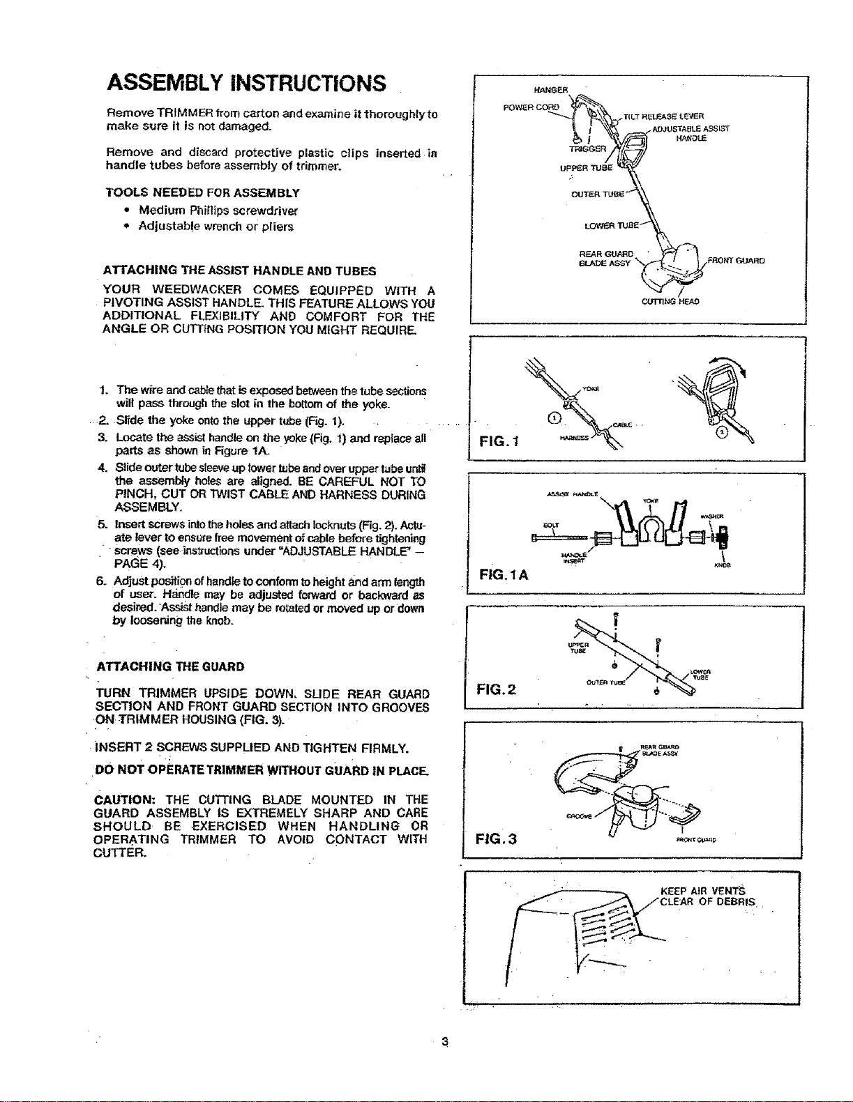
HANGER
POWERCORD "_
_JTER TUB _
LOt_VER TUgE
REAR GU.ARD '
6_ A Ft_21Nr 13_J_D
--,a' /
The wire and cabte that is exposed between the tube sections
will pass through the slot in the bottom of the yoke_ " ...... I] F i
...2, Slide the yoke onto the upper tube (Fig. 1). _.,
3, Locate the assist handle on the yoke (Fig. 1) and replace all
parts as shown in Rgure 1A. IG.
4, Slideoutertubesleeveuptowertubeandoveruppertubeunt_!
t_e assembly holes are aligned. BE CAREFUL NOT TO
PINCH, CUT OR TWIST CABLE AND HARNESS DURING
ASSEMBLY.
5. Insert screws into the holes and attach locknuts (Fig. 2). Actu-
ate lever to ensure free movement of cable before tightening
screws (see instructinns under "ADJUSTABLE HANDLE" --
PAGE 4).
6. Adjust position of handle to conform to height a_ndarm length FIG. 1A
of user. Handle may be adjusted forward or backward as
desired. Assist handle may be rotated or moved up or down
by loosening t_e knob.
ATTACHING THE GUARD
TURN TRIMMER UPSIDE DOWN, SLIDE REAR GUARD
SECTION AND FRONT GUARD SECTION INTO GROOVES
,ON TRIMMER HOUSING (FIG. 3).
iNSERT 2 SCREWS SUPPLIED AND TIGHTEN FIRMLY.
DO NOT OPERATE TRIMMER WITHOUT GUARD 1N PLACE.
FIG. 2
FIG. 3
CAUTION: THE CUTI'ING BLADE MOUNTED IN THE
GUARD ASSEMBLY IS EXTREMELY SHARP AND CARE
SHOULD BE EXERCISED WHEN HANDLING OR
OPERATING TRtMMER TO AVOID CONTACT WITH
CUTTER.
RF_R GU/,R=)
"' • KEEP AIR VENT_
. 3
Loading ...
Loading ...
Loading ...