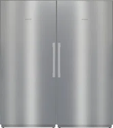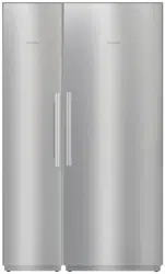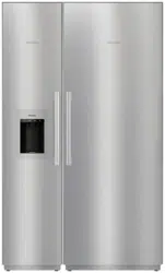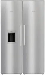
Pre-finished
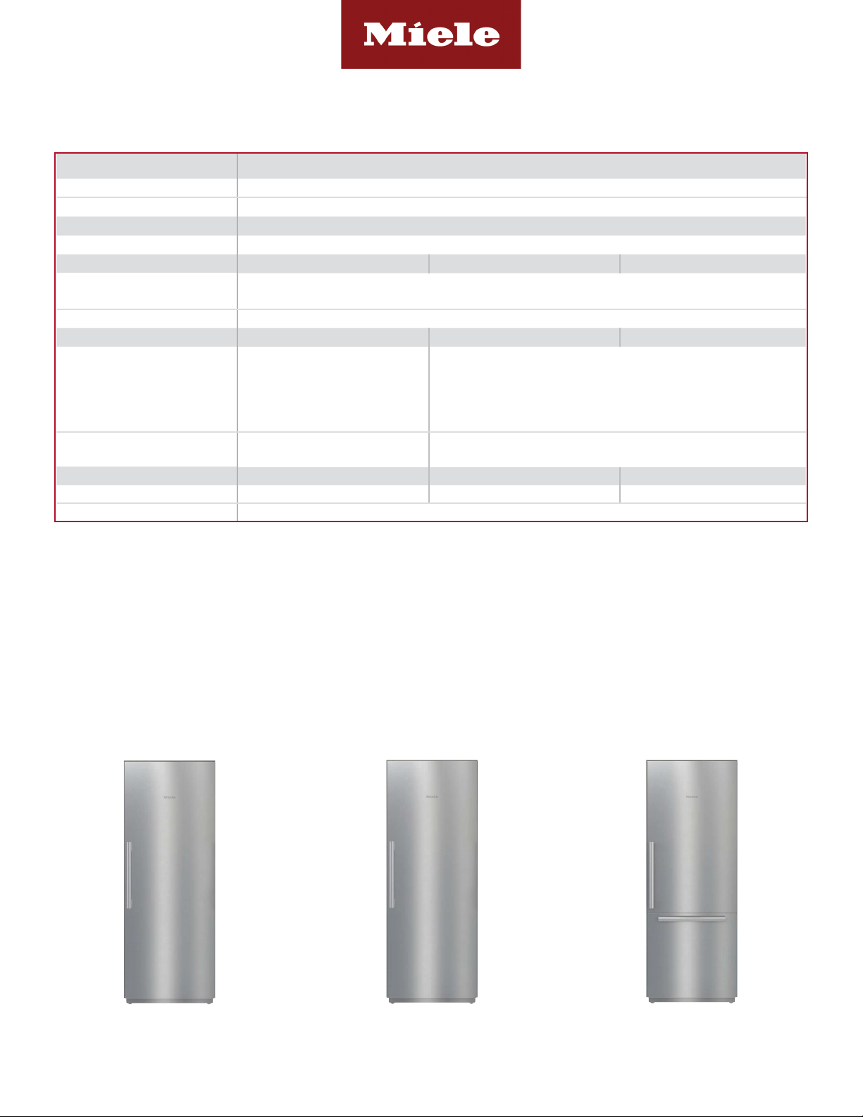
30” MasterCool
K 2802 SF
F 2812 SF
KF 2802 SF / KF 2812 SF
Shown: F 2472 SF merged with K 2802 SF
AFT
8mieleusa.comInfo subject to change Miele Help Desk (P): (800) 999-1360
Pre-finished
30” MasterCool
Please note the following:
• This specication sheet is for a single built-in unit.
• When combining multiple MasterCool units side-by-side, please refer to the Merging Kit specication sheet.
*If design calls for a partition less than 6
5
/16” (160 mm) the left unit’s cutout will require an additional
1
/8” (3 mm) to the width to allow installation of
the Heating Mat/Merge Kit.
SPECIFICATIONS
Overall Unit Dimensions 29
3
/4” (756 mm) W x 83
3
/4”- 85
3
/16” (2127 - 2164 mm) H x 24” (610 mm) D [Excludes Fascia Dimension]
Overall Fascia Dimensions 30
1
/2” (775 mm) W x 84”- 85
11
/16” (2134 - 2175 mm) H x 1
1
/2” (32 mm) D
Niche
Minimum Cabinet Niche Opening 30” (762 mm) W* x 84” - 85
3
/16” (2134 - 2164 mm) H x 24” (610 mm) D
Electrical
K 28x2 SF F 28x2 SF KF 28x2 SF
Electrical Requirements
110V / 120V, 60Hz, 15 Amps
In the case of side-by-side installations, a separate outlet must be used for each appliance.
Power Cord NEMA 5-15 plug, 5 ft (1.52 m)
Plumbing K 28x2 SF F 28x2 SF KF 28x2 SF
Water Supply Requirements -
Connect to a cold water supply only. Do not connect to a low-mineral or
a reverse osmosis system. Must be connected to a shut-off valve. The
water shut-off valve must be accessible after installation. The water pres-
sure must be between 29 psi (2 bar) and 116 psi (8 bar). If the pressure is
higher than 120 psi (8.3 bar), a pressure reducing valve must be installed.
Water Connection Line
-
Standard 1/4” O.D flexible water line. The maximum outer diameter of the
water pipe (without fittings): 3/8” (10 mm). Water line is not included.
Shipping
K 28x2 SF F 28x2 SF KF 28x2 SF
Shipping Weight 453 lbs (205.5 kg) 462 lbs (210 kg) 485 lbs (220 kg)
Shipping Dimensions 29
7
/8” (759 mm) W x 84
1
/4” (1,240 mm) H x 29
7
/8” (759 mm) D
K 2802 SF (Right Hinged)
Material# 11502700
F 2812 SF (Left Hinged)
Material# 11503350
KF 2802 SF (Right Hinged)
Material# 11502900
KF 2812 SF (Left Hinged)
Material# 11502910
Page 2 of 6
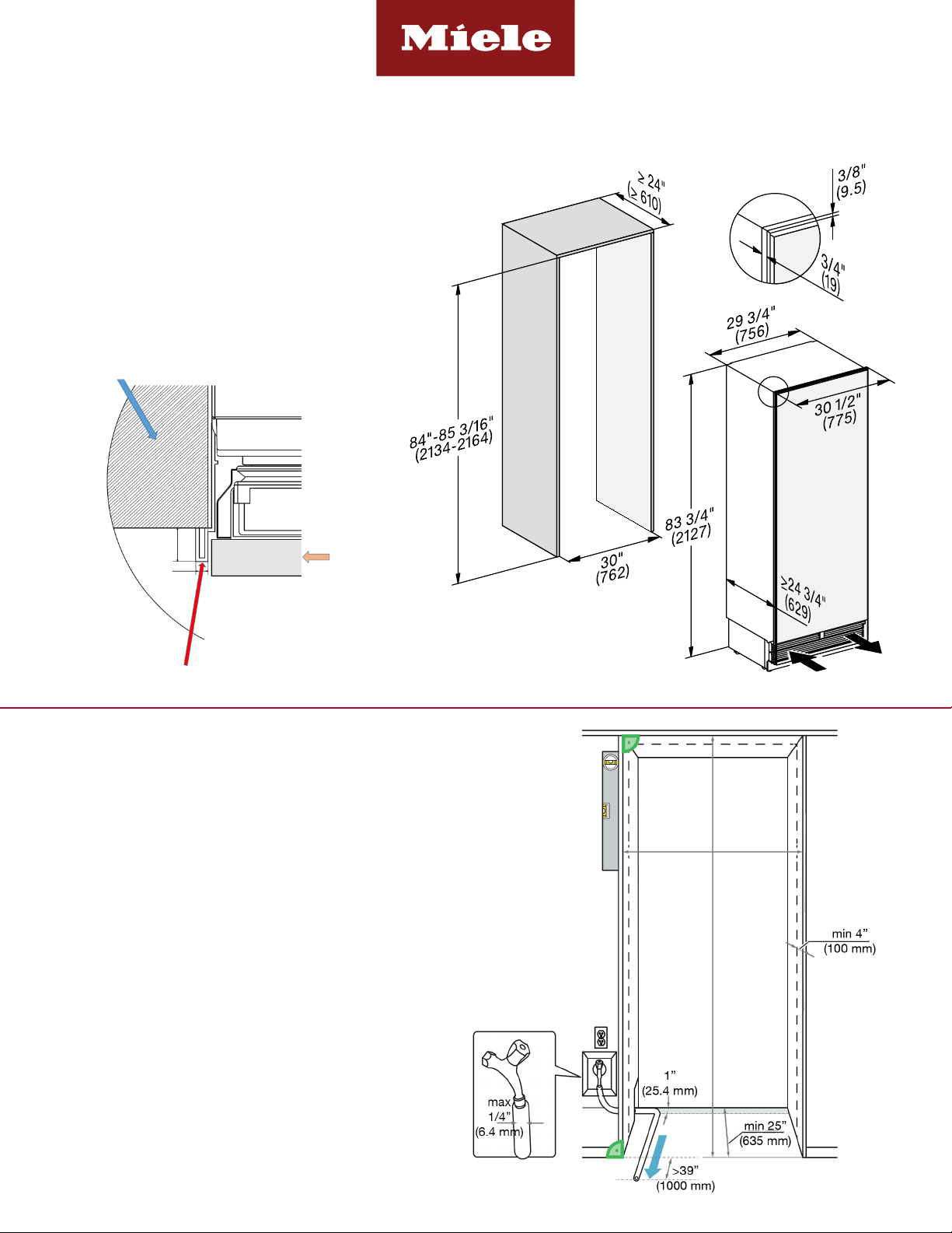
CUTOUT DIMENSIONS
Pre-finished
30” MasterCool
CUTOUT DETAILS
• The electrical connection must not be positioned higher
than 9” (228.6 mm) above the oor.
• The 1/4” (6.4 mm) plumbed water connection should
not be positioned higher than 2” (50.8 mm) above the
oor.
Notes:
In case of an emergency the electrical outlet must be
easily accessible and must not be concealed behind the
appliance.
Page 3 of 6
Please note unit’s outer SF frame.
Top view:
SF frame
9/32”
(7)
3/4”
(19)
Stainless steel door
Niche/Cabinetry
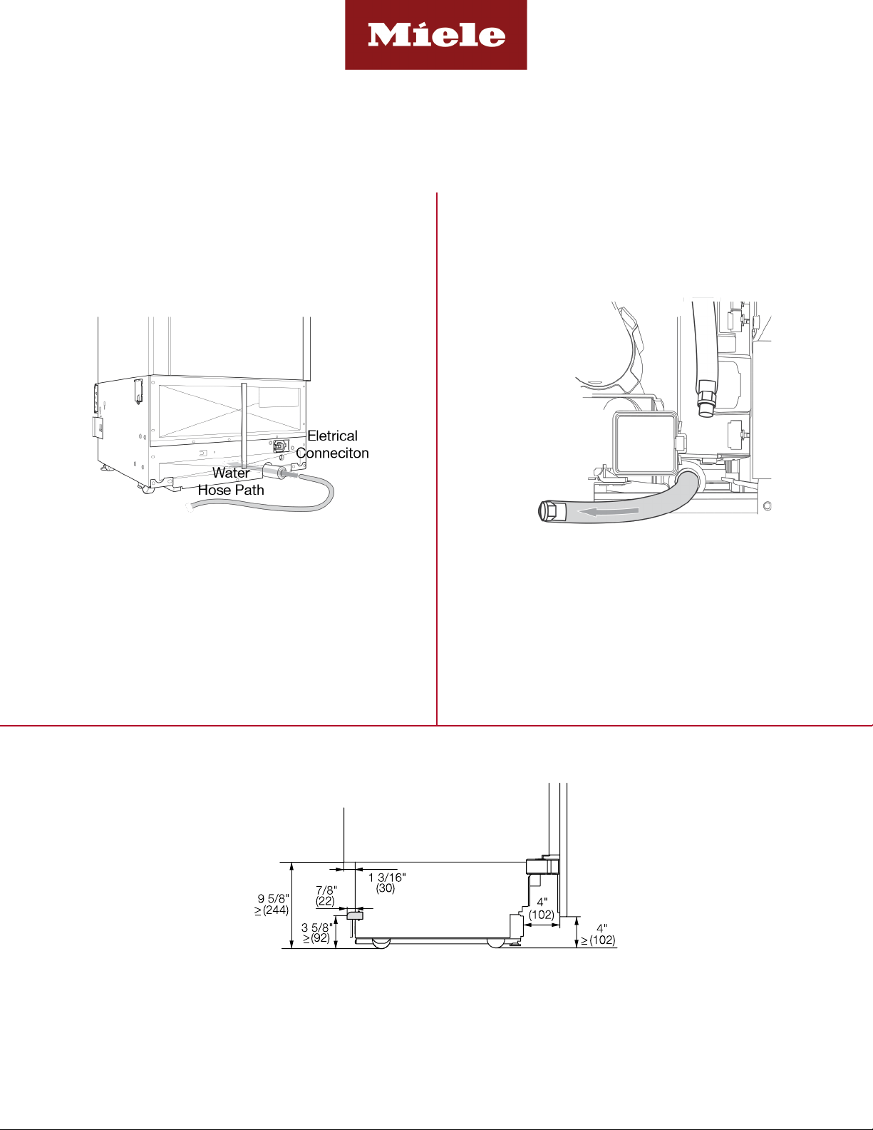
POWER SUPPLY AND WATER CONNECTION
(Water Connection For F 28x2 SF & KF 28x2 SF Only)
Pre-finished
30” MasterCool
Water connection is located in front of unit.
1/4” compression tting is needed.
Electrical - 5 foot (1.52 m) - 120 Volt - 15 Amp
- NEMA 5-15 molded plug
Water line - 1/4” exible water line - not included
Rear View Front View
Electrical
Connection
Side View
Page 4 of 6
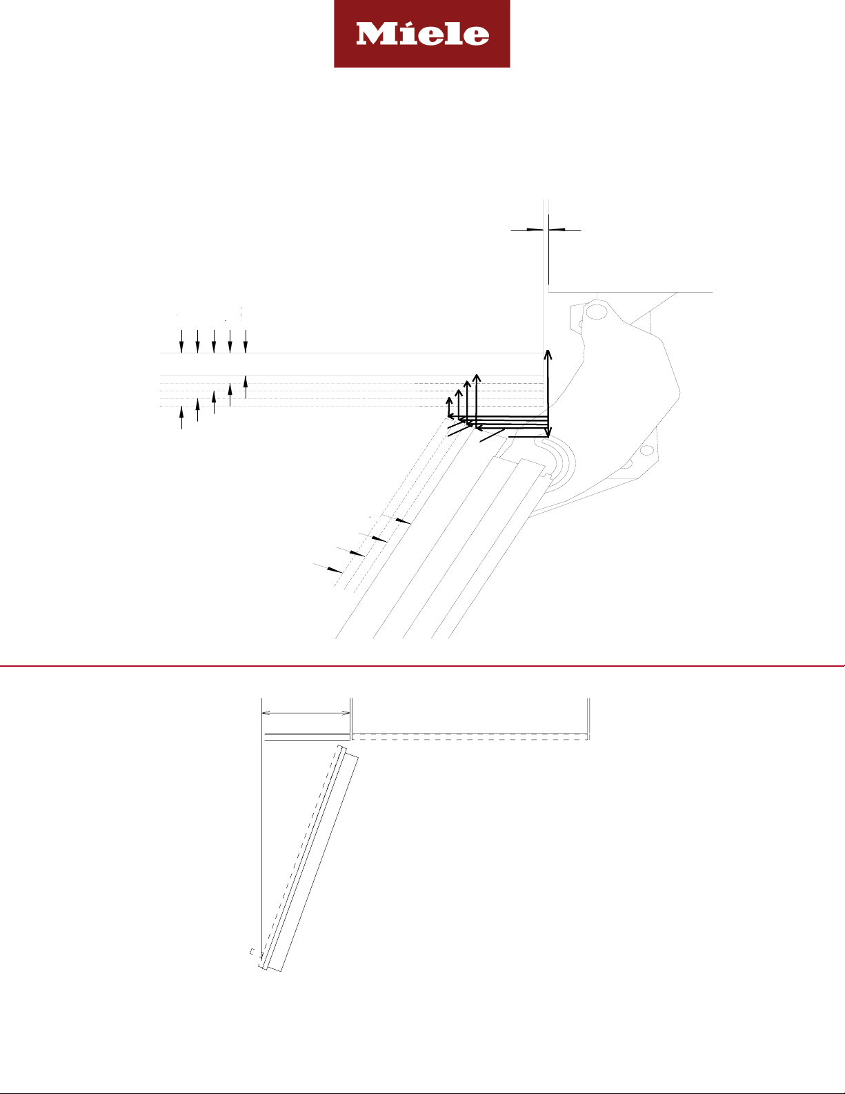
HINGING DETAILS 115° OPENING
Pre-finished
30” MasterCool
Available for the following models:
• K 28x2 SF
• F 28x2 SF
• KF 28x2 SF
Page 5 of 6
0-3/4"
1"
1-1/4"
1-1/2"
0-1/8"
F
ro
nt
Pa
n
el
0-3/4"
1-1/4"
1-1/2"
1-3/4"
1"
Cabinet Front
3”(76.2mm)
1-3/4”(44.5mm)
1-3/8”(35mm)
1-1/6”
(29.6mm)
1/4”(6.4mm)
17/24” (18mm)
2-1/24”(52mm)
2-1/3”
(59mm)
2-5/8”
(67mm)
3”(76.2mm)
1-3/4”(44.5mm)
1-3/8”(35mm)
1-1/6”
(29.6mm)
1/4”(6.4mm)
17/24” (18mm)
2-1/24”(52mm)
2-1/3”
(59mm)
2-5/8”
(67mm)
0-3/4” (19 mm)
1” (25 mm)
1-1/4” (32 mm)
1-1/2” (38 mm)
1-3/4” (44 mm)
1-1/2” (38 mm)
1-1/4” (32 mm)
1” (25 mm)
0-3/4” (19 mm)
0-1/8” (3 mm)
16 7/8"
MAX
NOTE: Additional space needed depending on
thickness of front panels and handle used
DOOR SWING AT 115° OPENING
11 3/4”
(298 mm)
Max
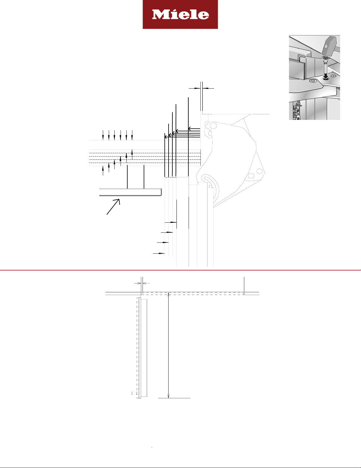
HINGING DETAILS 90° OPENING
Specification Sheets TRS 12152020
Pre-finished
30” MasterCool
Available for the following models:
• K 28x2 SF
• KF 28x2 SF
Page 6 of 6
0-1/8"
Front Panel
1"
1-1/4"
1-1/2"
0-3/4"
0-3/4"
1-1/4"
1-1/2"
1-3/4"
2"
1"
Cabinet Front
Door Swing
7/16”
(11 mm)
1-3/16”
(30mm)
1-7/16”
(36.5mm)
1-11/16”
(43mm)
1-15/16”
(49.2mm)
Handle or object that is
NOT ush with Cabinet
Front.
0-3/4” (19 mm)
1” (25 mm)
1-1/4” (32 mm)
1-1/2” (38 mm)
1-3/4” (44 mm)
2” (51 mm)
0-3/4” (19 mm)
1” (25 mm)
1-1/4” (32 mm)
1-1/2” (38 mm)
0-1/8” (3 mm)
When installing hinge side next to an appliance or object that is within range of the door panel,
limit the door opening angle to 90°. This is done by installing the banking pin as illustrated.
Insert the banking pin through the holes and drive in with a hammer.
of front panels and handle used.
Freezer units cannot be stop pinned at 90°
NOTE: Additional space needed depending on
thickness of front panels and handle used
38 11/16"
7/16"
DOOR SWING AT 90° OPENING
7/16” (11 mm)
32
11
/16” (830 mm)