Loading ...
Loading ...
Loading ...
34
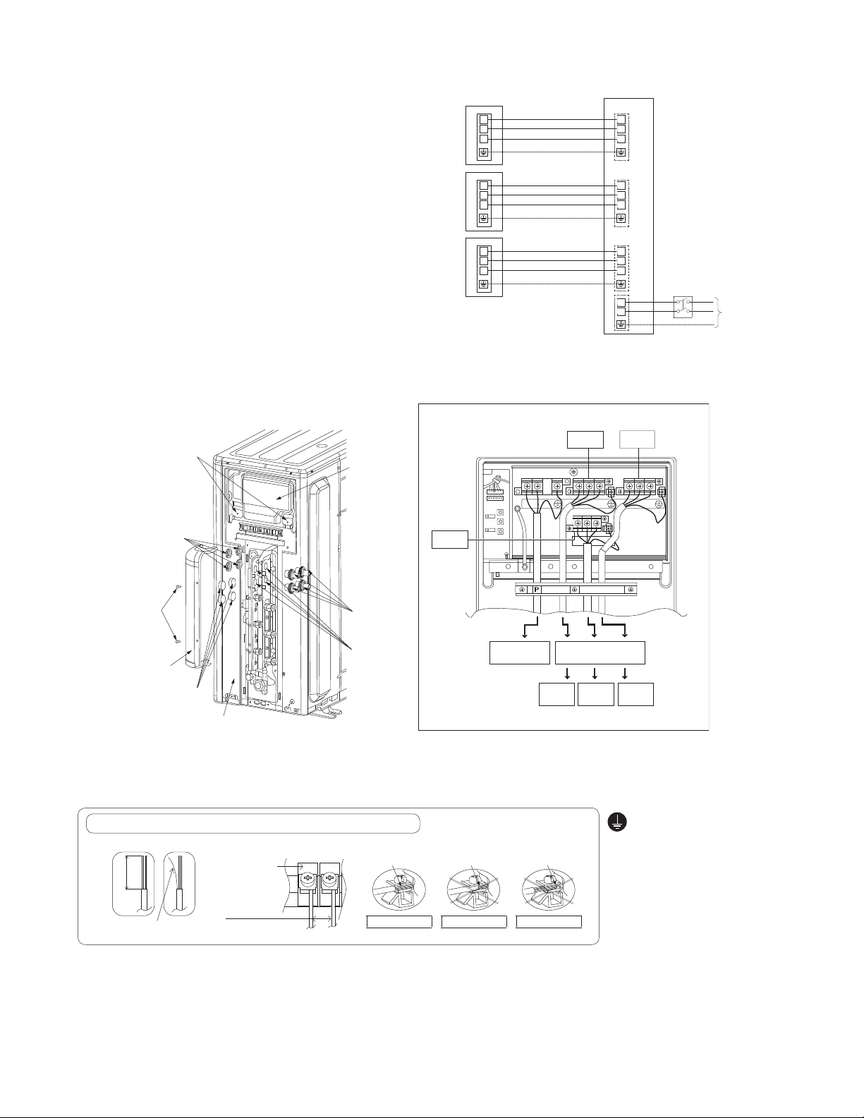
10.1.5 Connect The Cable To The Outdoor Unit
1. Remove Control Board Cover (Metal) by
loosening 2
scre
ws.
2.
Remove Valve Cover (Metal) by looseni
ng 2
sc
rews.
3.
R
emove Plugs
.
4. Fix the conduit connectors to the knock
out
hole
s with lock-nuts, then secure them.
5. Connecting wire between indoor unit and
outdoo
r unit should be UL listed or
CSA
approved 4 condu
ctor wires minimum AWG1
6
in accordance with local electric codes.
6. Wire Connection to the power supp
ly
(208/2
30V 60Hz) through circuit breake
r.
o Connect the UL liste
d or CSA approved
wire
s minimum AWG12 to
the terminal
board, and co
nne
ct to other end of the
wire
s to circuit breaker.
7.
Connect the power supply cord a
nd
con
necting wires between indoor unit an
d
outdoo
r unit according to the diagram as
shown.
8.
For wire stripping and connection requirement, refer to the diagram below.
9.
Secure the power supply cord and connection cables onto the control board with the holde
r.
10.
Attach the control board cover (metal and resin) and valve cover back to the original position with screw.
1
2
3
1
2
L1
L2
3
1
2
3
1
2
3
1
2
3
1
2
3
Outdoor Unit
Terminal
Unit B
Unit A
Unit C
Terminal
Terminal
Indoor
Unit B
Indoor
Unit A
Disconnect
Switch
Field supply
Grounding wire
Grounding wire min AWG16
Grounding wire min AWG16
Grounding wire min AWG16
Power Supply
Single Phase
208/230V 60Hz
min AWG12
208/230V min AWG16
208/230V min AWG16
208/230V min AWG16
208/230V min AWG16
208/230V min AWG16
208/230V min AWG16
208/230V min AWG16
208/230V min AWG16
208/230V min AWG16
Terminal
Indoor
Unit C
Each indoor unit must have its own conduit for the
wires between the indoor and outdoor unit but the
power supply for the outdoor unit must be in a separate
conduit to prevent potential communication problems.
Unit A
Unit C
Unit B
Connectors
Top panel
Plugs
Knock Out
Holes
Side Panel
Valve
Cover
(Metal)
Screws
Lock Nuts
Screws
Power Supply
Cord
Indoor & outdoor
connection cable
Indoor
Unit C
Indoor
Unit A
Indoor
Unit B
CU-3E19***
Control Board
Cover (Metal)
•
Ground wire must be Yellow/
Green (Y/G) in colour and
longer than other AC wires for
safety reasons.
This equipment must be
properly earthed.
Wire stripping
7
/
32
" (5 mm)
or more
(gap between
wires)
Noloosestrandwheninserted
Indoor/outdoor
connecting
terminal board
WIRE STRIPPING AND CONNECTING REQUIREMENT
Conductor fully
inserted
Conductor over
inserted
Conductor not
fully inserted
ACCEPT PROHIBITED PROHIBITED
13
/
32
"±
1
/
16
"
(10±1 mm)
Loading ...
Loading ...
Loading ...