Loading ...
Loading ...
Loading ...
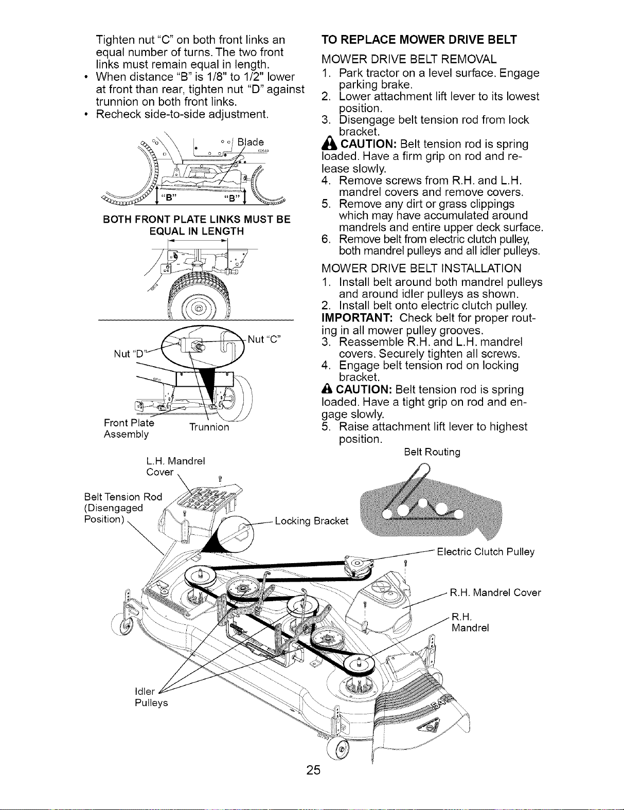
Tightennut"C"on bothfront linksan
equalnumberofturns.Thetwofront
linksmustremainequalin length.
Whendistance"B"is1/8"to 1/2"lower
atfrontthan rear,tightennut "D"against
trunnionon bothfrontlinks.
Recheckside-to-sideadjustment.
_':'o_X I oo/ Blade
o ° o o o2548
BOTH FRONT PLATE LINKS MUST BE
EQUAL IN LENGTH
Nut
Front Plate
Assembly
Trunnion
L.H. Mandrel
TO REPLACE MOWER DRIVE BELT
MOWER DRIVE BELT REMOVAL
1. Park tractor on a level surface. Engage
parking brake.
2. Lower attachment lift lever to its lowest
position.
3. Disengage belt tension rod from lock
bracket.
_i CAUTION: Belt tension rod is spring
loaded. Have a firm grip on rod and re-
lease slowly.
4. Remove screws from R.H. and L.H.
mandrel covers and remove covers.
5. Remove any dirt or grass clippings
which may have accumulated around
mandrels and entire upper deck surface.
6. Remove belt from electric clutch pulley,
both mandrel pulleys and all idler pulleys.
MOWER DRIVE BELT INSTALLATION
1. Install belt around both mandrel pulleys
and around idler pulleys as shown.
2. Install belt onto electric clutch pulley.
IMPORTANT: Check belt for proper rout-
ing in all mower pulley grooves.
3. Reassemble R.H. and L.H. mandrel
covers. Securely tighten all screws.
4. Engage belt tension rod on locking
bracket.
A CAUTION: Belt tension rod is spring
loaded. Have a tight grip on rod and en-
gage slowly.
5. Raise attachment lift lever to highest
position.
Belt Routing
Belt Tension Rod
(Disengaged
Position) _,,:;:;_,,
S/
Locking Bracket
Clutch Pulley
R.H. Mandrel Cover
Mandrel
Idler
Pulleys
25
Loading ...
Loading ...
Loading ...