Loading ...
Loading ...
Loading ...

8
Name and Function of
Parts
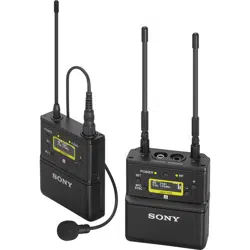
Body-pack transmitter (UTX-B40)
a Antenna
b POWER indicator
Displays the battery level.
c AUDIO (audio input level) indicator
Turns on or off according to the audio input level as
follows.
On (red): Audio input level is too high. If the sound is
distorted, adjust the attenuation level to decrease the
audio input level (page 28).
On (green): Audio input level is appropriate.
Off: There is no audio input or the input level is too low.
Flashing (orange): Audio is muted (i.e., disabled).
d Audio input connector (BMP type)
Connect to the supplied lavalier microphone.
• When the audio input level is set to MIC, a voltage for
the lavalier microphone power supply is applied to the
audio input connector. Special electrical wiring is used
inside the audio input connector for this purpose.
• If a lavalier microphone other than the one supplied is
connected, the proper performance may not be
obtained.
e Display section
A RF transmission indicator
Displays the current transmission status.
B RF transmission power indicator
Indicates the current transmission power setting. You can
change the setting with the RF transmission power setting
function.
For details on the RF transmission power setting
function, see “Setting the transmit output level (RF
POWER)” (page 29).
C Audio input level meter
Displays the audio input level.
D Peak indicator
Lights up when the signal is 3 dB below the level at which
distortion begins as a warning of excessive input level.
E Input level indicator
Displays the input level status.
: Microphone input
: Line input
F Muting status indicator
Displays an icon when the muting function is on.
For details about the muting function, see “Setting the
operation of the audio muting function (MUTE
SETTING) (UTX-B40/P40 only)” (page 29).
G Battery level indicator
Displays the battery level. “USB” is displayed when
power is supplied from the USB connector.
For details, see “Battery level indicator” (page 16).
H Menu display section
Displays various functions. Press the + or – button to
switch functions.
Indicator display Status
On (green) Sufficient battery level
Flashing (green) Battery is getting low
Off Supply OFF
Notes
: Transmitting
– : Transmission stopped
Loading ...
Loading ...
Loading ...