Loading ...
Loading ...
Loading ...
12
BOTTLE, KEG & BACK BAR COOLERS, GLASS & PLATE CHILLERS
OPERATIONS MANUAL
KEG TAPPING INSTRUCTIONS
Because keg and tap types vary from brand to brand, contact
your beer distributor for specific keg tapping instructions.
INSTALLATION OF CO
2
CYLINDER AND REGULATOR
Pressurized CO
2
should be provided from outside the cabinet.
The supply hose can be routed through the access hole at the
back of the machine compartment and into the cabinet through
the knock-out plug located on the upper side wall (see Figure
9). The CO
2
dispensing gas must be reduced to 8-10 PSI by a
regulator (not supplied) and delivered to the manifold splitter
(on the left upper wall of cabinet) using the supplied hose and
clamps. Cut hose to length. The manifold splitter will separate
the gas into two or more lines to supply each keg tap. A check
valve on the manifold splitter prevents beer from backing up into
the supply hose and regulator.
IMPORTANT NOTE: Changing Kegs: defrosting of all keg
coolers is automatic, but since loading times vary, unplug
the cabinet and leave the doors open for at least 15 min-
utes during keg change, to keep ice from accumulating on
the evaporator coil. The temperature control (on the left
rear interior) is factory set to maintain keg temperatures
within 35°F to 40°F under normal conditions. It may take
several hours to cool a warm keg, so cold kegs should
be moved from chilled storage immediately into your
cabinet, to avoid warm or spoiled product. Before a new
barrel is tapped, purge CO
2
lines by quickly opening and
closing the outlet valve, allowing a surge of gas to travel
through the line and tap.
NOTE: Proper cleaning is extremely important for the beer
faucet, drain pan and any items coming in contact with food
or beverages, to prevent odors and tastes from bacteria. It is
normal for some sweating on or around each draft tower and
door opening, under conditions of high humidity.
Model
No. of
Doors
Net Capacity
(Cu. Ft.)
Barrel-Type
Keg Qty.
Straight-Wall
Keg Qty.
KC24
1 8 1 1
KC50
2 16 - 2
KC50S
2 13 - 2
KC59
2 22 2 3
KC59S
2 15 2 2
KC69
2 26 3 3
KC69S
2 18 3 3
KC79
3 28 4 4
KC79S
3 22 3 3
KC90
3 35 4 5
KC90S
3 25 4 4
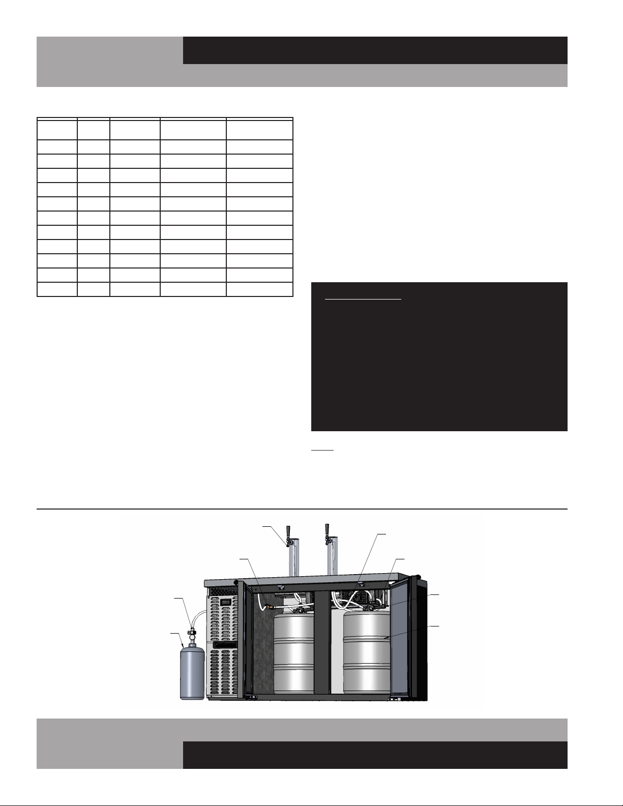
DIRECT DRAW DRAFT BEER SET-UP (Keg Coolers)
Your new unit will provide cold storage for barrel-type or
straight-side kegs (see Table above for capacities). To install
dispensing towers (see Figure 9), place a rubber washer over
tower mounting holes in the top of the cabinet and secure
tower(s) using fine thread machine screws supplied in cabinet
top (do not use wood screws supplied with tower). The hose
line from tower must go through hole in top and be attached to
the keg tap (supplied by others). Install the cold air tubes from
inside the cabinet by pushing each tube as far as it will go into
its closest tower hole. About 8” of tube will feed into the tower.
For your convenience, a cleanout drain hose is provided from
the behind the front grill with 3 ft. of hose for an external drain
connection to be made by installer. If a beer waste jar is to be
installed, the drain line (on the left front interior floor) can be cut.
Keg Cooler Capacities
w/COOLING HOSE
(BY OTHERS)
CO2 TANK
COLD AIR HOSE
REGULATOR
KEG TAP
C02 HOSES
(BY OTHERS)
DISPENSING TOWER
KEGS
(BY OTHERS)
(BY OTHERS)
(BY OTHERS)
MANIFOLD
SPLITTER
FIGURE 9:
Typical Keg Cooler Tap Set-Up
Loading ...
Loading ...
Loading ...