
Loading ...
Loading ...
RZ45 / TR86 / CS-5 User Manual
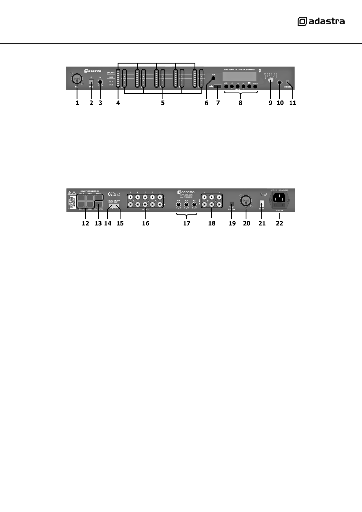
Front panel
Rear panel
Connection
Ensure the Power (21) is switched off until all input and output connections are in place.
The RZ45 is supplied with a TR86 wall remote control, which is required to operate one of the output zones.
Up to 4 more TR86 wall remote controls can be added to the system, depending on how many zones are
being deployed. Connect the supplied TR86 remote to one of the remote inputs (12) on the RZ45 rear panel
using standard network cable.
For remote announcement to all or any zones, an optional CS-5 call station (953.049UK) can be added to the
system. If a CS-5 call station is being used, connect this to the call station input (13) on the rear panel using
network cable.
For announcements to all zones from the main RZ45 unit, a paging microphone input is provided on the front
or rear panel (1, 20). If the paging microphone requires phantom power (e.g. condenser mic), enable this by
pressing in the phantom power button (19)
Each TR86 remote control can select an audio source from 1, 2, 3 or 4/USB. Audio sources 1, 2 and 3 are line
inputs which can be connected to the rear panel of the RZ45 via L+R RCA sockets (18). The output level for
each of these can be trimmed using rotary level controls (17) to avoid overloading the zone output.
1.
Paging microphone input (XLR)
7.
USB port
2.
Page on/off button & indicator
8.
Media player controls & display
3.
Paging microphone level
9.
Monitor zone select
4.
Output zones level indicators
10.
Monitor level
5.
Output zones source indicators
11.
Monitor headphones output (3.5mm jack)
6.
Stereo AUX input (3.5mm jack)
12.
TR86 remote control inputs (RJ45)
18.
Line inputs (L+R RCA)
13.
CS-5 call station input (RJ45)
19.
+24V phantom power (to paging mic)
14.
24Vdc emergency mute contacts
20.
Paging microphone rear input (XLR)
15.
Emergency audio line input
contacts
21.
Mains power on/off switch
16.
Zone outputs (L+R RCA)
22.
Mains power inlet (IEC) with fuse holder
17.
Line input levels
Loading ...
Loading ...
Loading ...