Loading ...
Loading ...
Loading ...
11
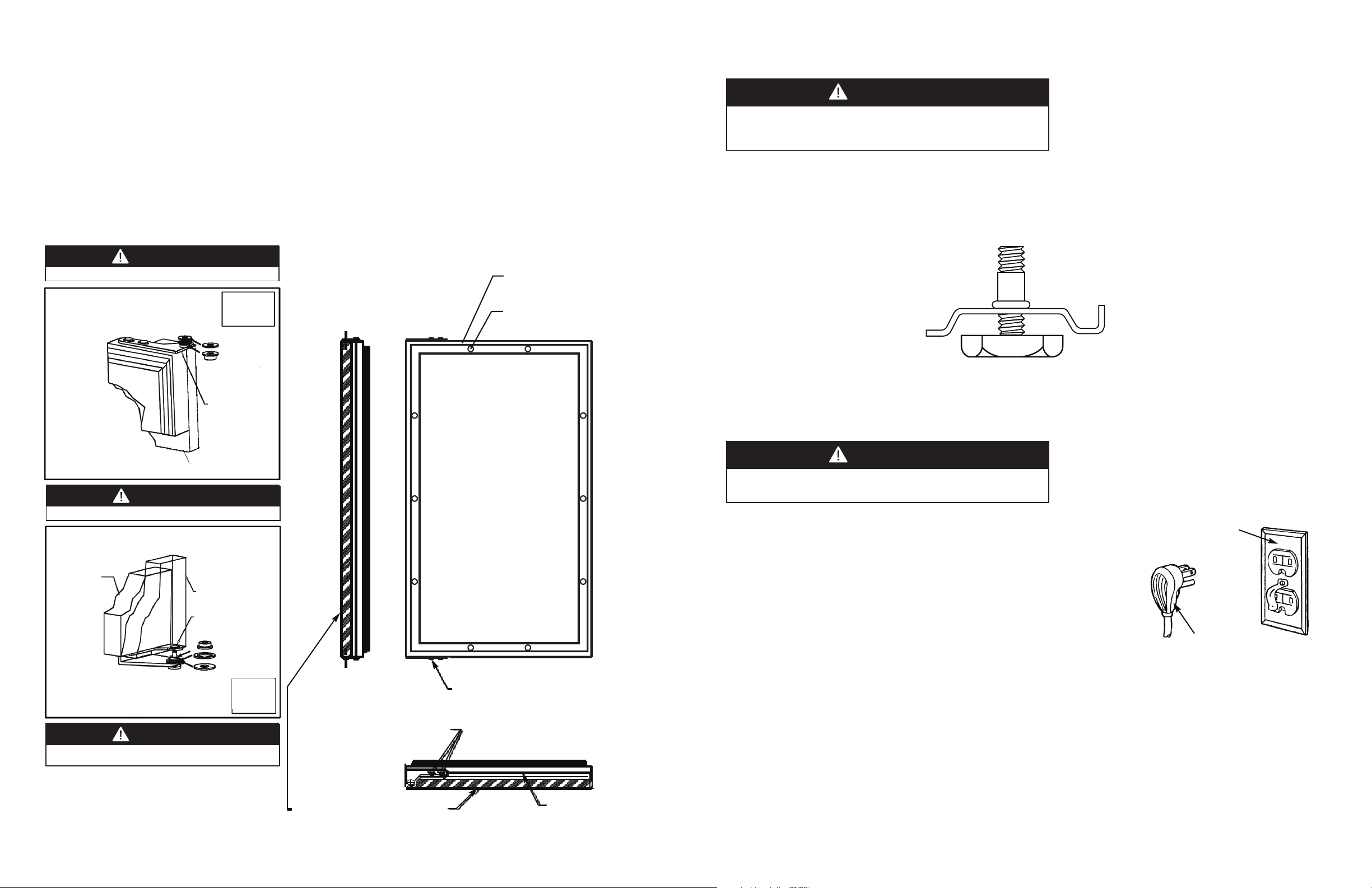
LEG LEVELER INSTALLATION
RReeaadd BBeeffoorree IInnssttaalllliinngg LLeegg LLeevveelleerrss
1. Four leveling legs are pre-installed in the base of the unit at the factory.
2. The unit should be leveled from front to back and side to side. If floor conditions do not allow the unit to sit level , adjust
the leg levelers by turning the required leg leveler counter-clockwise to increase the height and clockwise to reduce the
height.
10
ATTACHING THE OVERLAY PANEL TO THE DOOR
1. If the door is attached to the unit, remove by unscrewing the top Allen head set screw at the top hinge. Remove
the door by angling the door off of the bottom hinge pin.
2. Peel back the door gasket to expose the screw holes.
3
. Set the overlay panel flush to the front of the door in the desired location. Clamp the overlay panel to the door if
n
ecessary.
4
. Insert the wood screws through the back of the door into the pilot holes in the overlay panel and tighten.
5
. Reinstall the door gasket by pressing into the door channel. Make certain the corners are inserted fully.
6. Install the door to the unit. Use the supplied plastic washer as shown in the figure below.
7. Realigning the door may be necessary. Any final door adjustments can be made using a 5/32” Allen head driver to
adjust the door’s brackets. (See figure below)
8. Attach the door to the unit by reversing step number 1 above.
WARNING
Do not lay unit on top, side, back, or front. If unit is accidentally laid in
any position other than right side up, then the unit must remain in the
right side up position for at least 24 hours before plugging the unit in.
1/8” ALLEN HEAD
FOR HINGE
Hinge Hardware Installation Details
BOTTOM OF DOOR
ATTACHED OVERLAY PANEL
DOOR HINGE
ADJUSTMENT SCREWS
(
2) NYLON
H
ARDWARE
C
OMPONENTS
A
T TOP HINGE
TOP HINGE CORNER
OVERLAY PANEL
DOOR HINGE
BUSHING BRACKET
SHOULDER BUSHING
.625 OD X .218 ID
WASHER
BOTTOM HINGE CORNER
REFRIGERATOR
DOOR
OVERLAY PANEL
DOOR HINGE
BUSHING BRACKET
SHOULDER BUSHING
(3) NYLON
HARDWARE
COMPONENTS
AT BOTTOM
HINGE
.75 OD X .443 ID
WASHER
.75 OD X .257 ID
WASHER
SCREWS
ADJUSTMENT
5/32” ALLEN HEAD SCREWS
FOR HINGE ADJUSTMENT
0 3/8” CLEARANCE HOLES
FOR SCREWS
8 HOLES
Ø 3/8” CLEARANCE HOLES
FOR SCREWS - 10 HOLES
MAGNETIC
DOOR GASKET
REAR OF DOOR
CAUTION
Door can become disengaged if washers are not installed.
CAUTION
D
oor can become disengaged if washers are not installed.
CAUTION
Door may not swing properly if all nylon components are not
installed as shown.
ELECTRICAL CONNECTION
Electrical Requirements
A 115 volt, 60 Hz, AC only 15 amp fused electrical supply is required. (A time
delay fuse or circuit breaker is recommended.) It is recommended that a
separate circuit, serving only this appliance, be provided.
•ELECTRICAL GROUND IS REQUIRED ON THIS APPLIANCE.
•DO NOT UNDER ANY CIRCUMSTANCES REMOVE THE POWER SUPPLY
CORD GROUND PLUG.
•DO NOT USE AN EXTENSION CORD.
Recommended Grounding Methods
For your personal safety, this refrigeration product must be grounded. This appliance is equipped with a 5’ power
supply cord having a 3-prong grounding plug. To minimize possible shock hazard, the cord must be plugged into a
mating 3-prong grounding type wall receptacle grounded in accordance with the National Electrical Code and local
codes and ordinances. If the circuit does not have a grounding type receptacle, it is the responsibility and obligation of
the customer to exchange the existing receptacle in accordance with the National Electrical Code and applicable local
codes and ordinances. The third ground plug SHOULD NOT, under any circumstances, be cut or removed. All UL listed
refrigerated products are equipped with this type of plug.
WARNING
ELECTRICAL SHOCK HAZARD
Failure to follow these instructions could result in fire or electrical shock.
Grounding type
wall receptacle
Power Supply
with 3-prong
grounding plug
Loading ...
Loading ...
Loading ...