Loading ...
Loading ...
Loading ...
4
510
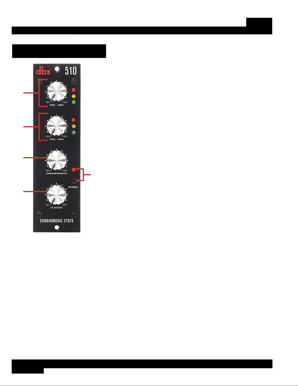
The User Interface
1
3
4
5
2
1. 36 Hz–56 Hz Control w/ Synthesis Level Indicator LEDs
This control adjusts how much of the subharmonic synthesis effect is
applied in the 36 Hz-56 Hz frequency band.
The LEDs to the right of the control indicate the signal level of the
effect within the band, with green indicating signal present, amber
indicating the signal is approaching clipping, and red indicating clipping.
If the red LED lights, the 36 Hz-56 Hz control or output level of the
previous device should be reduced to prevent distortion.
2. 24 Hz–36 Hz Control w/ Synthesis Level Indicator LEDs
This control adjusts the subharmonic synthesis level applied in the 24
Hz-36 Hz frequency band.
The LEDs to the right of the control indicate the signal level of the
effect within the band, with green indicating signal present, amber
indicating the signal is approaching clipping, and red indicating clipping.
If the red LED lights, the 24 Hz-36 Hz control or output level of the
previous device should be reduced to prevent distortion.
3. SUBHARMONICS Control
Where the 24 Hz-36 Hz and 36 Hz-56 Hz controls adjust the level of
the respective frequency bands, this control adjusts the overall amount
of subharmonic synthesis effect applied to the signal. Adjust it until the
desired amount of overall effect is achieved.
4. LF BOOST Control
This control is used to even out the total apparent bass output of the
processed signal. Use it to fill in the “gap” between the synthesized low
bass (below 56 Hz) and the mid bass of the original program. Be careful
that you don’t apply excessive boost, especially if the SUBHARMONICS
control is past its midpoint or if you are using bass equalization
somewhere else in the signal chain.
Note that the LF BOOST control can also be used alone when no
subharmonic synthesis effect is applied (this is acheived by setting the
SUBHARMONICS control to its full counter-clockwise position).
5. BYPASS Button & LED
When this button is disengaged, the LED will not light and the signal will pass through the 510’s processing circuit.
When engaged, the LED will light and processing will be bypassed. Note that this is a hard-wired bypass for optimum
signal integrity when bypassing the processor. Use this button to audition the difference between the processed and
unprocessed signals.
Loading ...
Loading ...
Loading ...