

's !
®
Model No.
152.211620
c_us
FOR YOUR OWN SAFETY; Read
and foUlow all of the Safety and
Operating Instructions before
Operating this Bench Grinder
Sears, Roebuck and Co°, Hoffman Estates, IL 60179 U.S.A.
Part No. 0R93650
Customer Helpline
1-800-897-7709
PReasehave your ModeUNo.
and SedaRNo. availabUe.
EspaSol pg. 19

SECTION PAGE
Warranty .......................................................................................................................................................................... 2
Product Specifications ................................................................................................................................................... 2
Safety Instructions ......................................................................................................................................................... 3
Grounding Instructions .................................................................................................................................................. 5
Specific Safety Instructions for Bench Grinders ........................................................................................................ 6
Accessories and Attachments ...................................................................................................................................... 6
Carton Contents ............................................................................................................................................................. 7
Know Your Bench Grinder ............................................................................................................................................. 8
Assembly Instructions ................................................................................................................................................... 9
Operating the Bench Grinder ...................................................................................................................................... 12
Maintenance .................................................................................................................................................................. 15
Troubleshooting Guide ................................................................................................................................................ 15
Parts List ....................................................................................................................................................................... 16
Espaffol .......................................................................................................................................................................... 19
Service Information ...................................................................................................................................... Back Cover
ONE-YEAR FULL WARRANTY ON CRAFTSMAN PROFESSIONAL TOOL
if this Craftsman tool fails due to a defect in material or workmanship within one year from the date of purchase,
CALL 1-800-4-MYoHOME@ TO ARRANGE FOR FREE REPAIR,
This warranty applies only while this tool is in the United States,
This warranty gives you specific legal rights, and you may also have other rights, which vary, from state to state,
Sears, Roebuck and Co,, Dept, 817WA, Hoffman Estates, IL 60179 06/05
Motor
Continuous Duty HP
Maximum HP developed
Volts
Hertz
RPM
Grinding Wheel Size
Grinding Wheel Grit
Lamp
Tool Rests
Eye Shield Assemblies
Spark Arrestors
Quench tray
1/2
1/5
120
60
1725 R,P,M to 3450 R,P,M,
(no load speed)
8" x 1" x 5/8"
60
120V, 40 watt or less Track
Light Bulb, Type R20,
medium base or equivalent
(not included)
Left and Right
Clear Lexan Left and Right
Left and Right
6" x 2" x 2"
To avoid electrical shock to yourself and damage to the
Bench Grinder, use proper circuit protection,
The Bench Grinder is factory wired for 120V, 60 Hz,
operation, Connect to a 120V, 15 amp branch circuit
and use a 15 amp time delay fuse or circuit breaker,
The electrical circuit cannot have any wire size less
than #14, To avoid shock or fire, replace power cord
immediately if it is damaged in any way,
GENERAL SAFETY iNSTRUCTiONS
Operating a Bench Grinder can be dangerous if safety
and common sense are ignored, The operator must be
familiar with the operation of the tool, Read this manual
to understand this Bench Grinder, DO NOT operate this
Bench Grinder if you do not fully understand the limita-
tions of this tool, DO NOT modify this Bench Grinder in
any way,
BEFORE USUNG THE BENCH GRUNDER
9,
10,
11,
12,
CHmLDPROOF THE WORKSHOP AREA by remov-
ing switch keys, unp,ugging tools from the electrical
recaptacles, and using padlocks,
DO NOT use electrical tools in the presence of
flammable liquids or gasses,
ALWAYS UNPLUG THE TOOL FROM THE ELEC-
TRmCAL RECEPTACLE when making adjustments,
changing parts or performing any maintenance,
KEEP PROTECTmVE GUARDS mNPLACE AND mN
WORKmNG ORDER,
To avoid serious injury and damage to the tool, read
and follow all of the Safety and Operating instructions
before operating the Bench Grinder,
2,
3,
4,
5,
READ the entire Owner's Manual, LEARN how to
use the tool for its intended applications,
GROUND ALL TOOLS, if the tool is supplied with a
3oprong plug, it must be plugged into a 3-contact
electrical receptacle, The 3rd prong is used to
ground the tool and provide protection against
accidental electric shock, DO NOT remove the 3rd
prong, See Grounding instructions on page 4,
AVOID A DANGEROUS WORKING ENVIRON-
MENT. DO NOT use electrical tools in a damp
environment or expose them to rain,
DO NOT use electrical tools in the presence of
flammable liquids or gasses,
ALWAYS keep the work area clean, well lit, and
organized, DO NOT work in an environment with
floor surfaces that are slippery from debris, grease,
and wax,
6,
7,
KEEP VISITORS AND CHILDREN AWAY. DO NOT
permit people to be in the immediate work area,
especially when the electrical tool is operating,
DO NOT FORCE THE TOOL to perform an opera-
tion for which it was not designed, it wiii do a safer
and higher quality job by only performing operations
for which the tool was intended,
8, WEAR PROPER CLOTHING. DO NOT wear loose
clothing, gloves, neckties, or jewelry, These items
can get caught in the machine during operations
and pull the operator into the moving parts, The
user must wear a protective cover on their hair, if
the hair is long, to prevent it from contacting any
moving parts,
13,
14,
15,
16,
17,
17,
19,
20,
21,
AVOID ACCIDENTAL STARTING, Make sure that
the power switch is in the "OFF" position before
plugging in the power cord to the electrical
receptacle,
REMOVE ALL MAINTENANCE TOOLS from the
immediate area prior to turning "ON" the Bench
Grinder,
USE ONLY RECOMMENDED ACCESSORIES,
Use of incorrect or improper accessories could
cause serious injury to the operator and cause
damage to the tool, if in doubt, check the instruction
manual that comes with that particular accessory,
NEVER LEAVE A RUNNING TOOL UNATTENDED,
Turn the power switch to the "OFF" position, DO
NOT leave the tool until it has come to a complete
stop,
DO NOT STAND ON A TOOL, Serious injury could
result if the tool tips over or you accidentally contact
the tool,
DO NOT store anything above or near the tool
where anyone might try to stand on the tool to
reach it.
MAINTAIN YOUR BALANCE. DO NOT extend
yourself over the tool, Wear oil resistant rubbersoled
shoes, Keep floor clear of debris, grease, and wax,
MAINTAIN TOOLS WITH CARE, Always keep tools
clean and in good working order, Keep all blades
and tool bits sharp,
EACH AND EVERY TIME, CHECK FOR DAMAGED
PARTS PRIOR TO USING THE TOOL, Carefully
check all guards to see that they operate properly,
are not damaged, and perform their intended func-
tions, Check for alignment, binding or breaking of
moving parts, A guard or other part that is damaged
should be immediately repaired or replaced,
SAVE THESE INSTRUCTIONS.
22, CHILDPROOF THE WORKSHOP AREA by remov-
ing switch keys, unpUugging tooUs from the eUectricaU
receptacles, and using padUocks,
23, DO NOT OPERATE TOOL IF UNDER THE INFLU-
ENCE OF DRUGS OR ALCOHOL,
24, SECURE ALL WORK, When it is possiMe, use
damps or jigs to secure the workpiece, This is
safer than attempting to hoUdthe workpiece with
your hands,
25, STAY ALERT, WATCH WHAT YOU ARE DOING,
AND USE COMMON SENSE WHEN OPERATING
A POWER TOOL. DO NOT USE A TOOL WHILE
TIRED OR UNDER THE INFLUENCE OF DRUGS,
ALCOHOL, OR MEDmCATmON,A moment of in-
attention while operating power tooUs may resuUtin
serious personaU injury,
26, ALWAYS WEAR A DUST MASK TO PREVENT
INHALING DANGEROUS DUST OR AIRBORNE
PARTICLES, incUuding wood dust, crystalline silica
dust and asbestos dust, Direct particles away from
face and body, AUwaysoperate tooUin well venth
Uatedarea and provide for proper dust removal Use
dust collection system wherever possible, Exposure
to the dust may cause serious and permanent res-
piratory or other injury, including silicosis (a serious
lung disease), cancer, and death, Avoid breathing
the dust, and avoid prolonged contact with dust,
Allowing dust to get into your mouth or eyes, or lay
on your skin may promote absorption of harmful
material, Always use properly fitting NIOSH/OSHA
approved respiratory protection appropriate for the
dust exposure, and wash exposed areas with soap
and water,
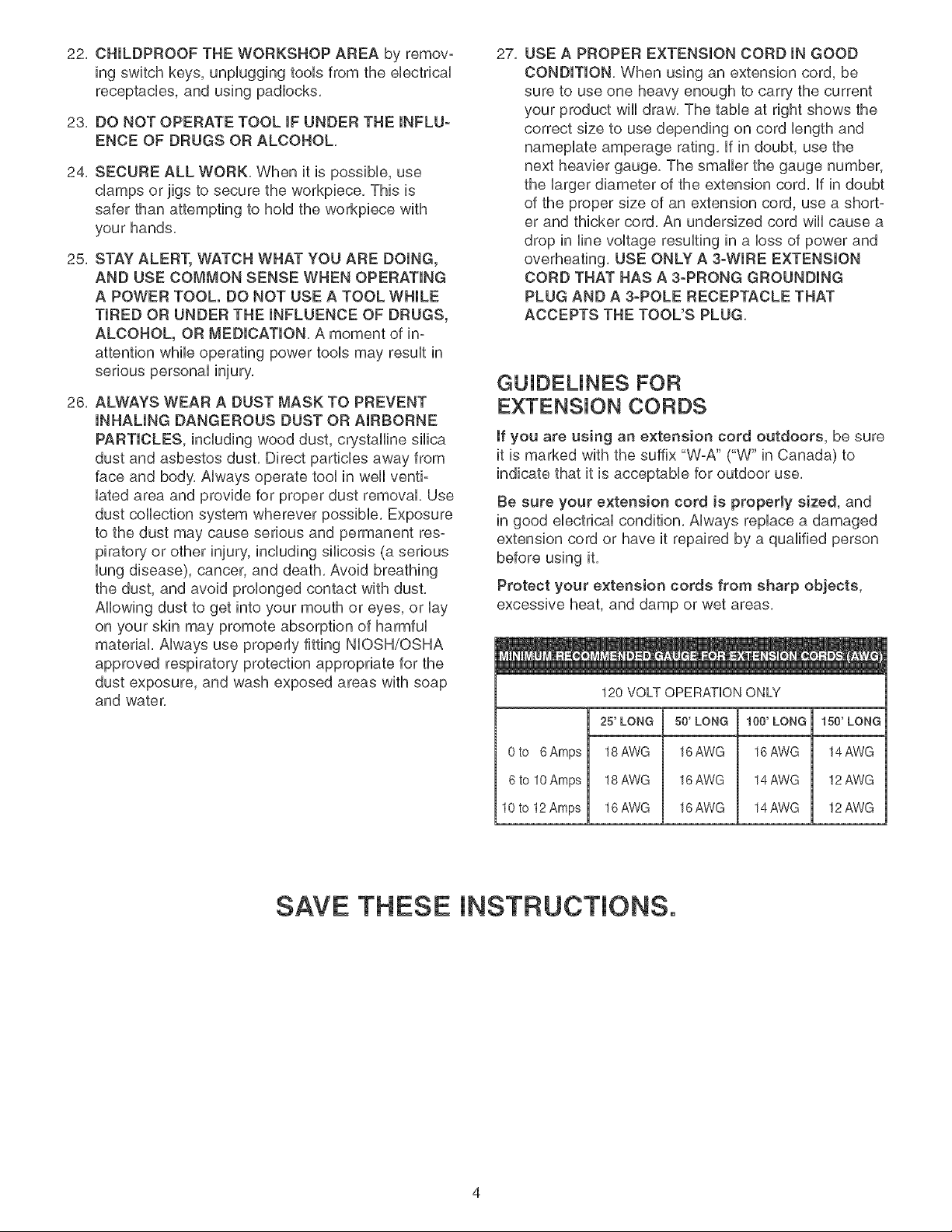
27, USE A PROPER EXTENSION CORD IN GOOD
CONDITION, When using an extension cord, be
sure to use one heavy enough to carry the current
your product will draw, The table at right shows the
correct size to use depending on cord length and
nameplate amperage rating, If in doubt, use the
next heavier gauge, The smaller the gauge number,
the larger diameter of the extension cord, If in doubt
of the proper size of an extension cord, use a short-
er and thicker cord, An undersized cord will cause a
drop in line voltage resulting in a loss of power and
overheating, USE ONLY A 3-WIRE EXTENSION
CORD THAT HAS A 3-PRONG GROUNDING
PLUG AND A 3-POLE RECEPTACLE THAT
ACCEPTS THE TOOL'S PLUG,
GUJDEUNES FOR
EXTENSION CORDS
If you are using an extension cord outdoors, be sure
it is marked with the suffix "W-A" CW" in Canada) to
indicate that it is acceptable for outdoor use,
Be sure your extension cord is properly sized, and
in good electrical condition, Always replace a damaged
extension cord or have it repaired by a qualified person
before using it,
Protect your extension cords from sharp objects,
excessive heat, and damp or wet areas,
120 VOLT OPERATION ONLY
25' LONG 50' LONG 100' LONG 150' LONG
0to 6Amps 18AWG 16AWG 16AWG 14AWG
6 to 10 Amps 18 AWG 16 AWG 14 AWG 12 AWG
10to 12Amps 16AWG 16AWG 14AWG 12AWG
SAVE THESE INSTRUCTIONS.
THIS TOOL MUST BE GROUNDED WHILE iN USE
TO PROTECT THE OPERATOR FROM ELECTRIC
SHOCK.
mNTHE EVENT OF A MALFUNCTION OR BREAK-
DOWN, grounding provides the path of bast resistance
for eUectriccurrent and reduces the risk of eUectric
shock, This tooUis equipped with an eUectric cord that
has an equipment grounding conductor and a ground-
ing pUug,The pUugMUST be pUugged into a matching
eUectdcaUreceptacb that is properUy installed and ground-
ed in accordance with ALL bcaU codes and ordinances,
DO NOT MODIFY THE PLUG PROVIDED, if it wHUnot
fit the eUectricaUreceptacb, have the proper eUectrbaU
receptacle installed by a qualified electrician,
iMPROPER ELECTRICAL CONNECTION of the equip-
ment grounding conductor can result in risk of electric
shock, The conductor with the green insulation (with or
without yellow stripes) is the equipment grounding
conductor, DO NOT connect the equipment grounding
conductor to a live terminal if repair or replacement of
the electric cord or plug is necessary,
CHECK with a qualified electrician or sewice personnel
if you do not completely understand the grounding
instructions, or if you are not sure the tool is properly
grounded,
USE ONLY A 3-WIRE EXTENSION CORD THAT HAS
A 3-PRONG GROUNDING PLUG AND A 3-POLE
RECEPTACLE THAT ACCEPTS THE TOOL'S PLUG.
REPLACE A DAMAGED OR WORN CORD IMMED-
iATELY.
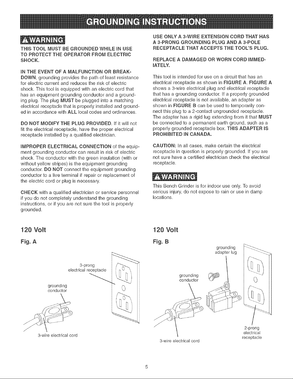
This tool is intended for use on a circuit that has an
electrical receptacle as shown in FIGURE A, FIGURE A
shows a 3-wire electrical plug and electrical receptacle
that has a grounding conductor, if a properly grounded
electrical receptacle is not available, an adapter as
shown in FIGURE B can be used to temporarily con-
nect this plug to a 2-contact ungrounded receptacle,
The adapter has a rigid lug extending from it that MUST
be connected to a permanent earth ground, such as a
properly grounded receptacle box, THIS ADAPTER iS
PROHIBITED IN CANADA.
CAUTION: in all cases, make certain the electrical
receptacle in question is properly grounded, if you are
not sure have a certified electrician check the electrical
receptacle,
This Bench Grinder is for indoor use only, To avoid
serious injury, do not expose to rain or use in damp
locations,
120 Volt
Fig. A
3-prong
electrical receptacle
grounding
conductor
3-wire ebctricaI cord
120 Volt
Fig. B
grounding
conductor
grounding
adapter lug
/ 2-prong
electrica!
receptacle
3-wire electrical cord
SPECiFiC SAFETY JNSTFIUCTJONS
FOR BENCH GRINDERS
The operation of any grinder can result in debris being
thrown into your eyes, which can result in severe eye
damage, ALWAYS WEAR EYE PROTECTION, Any
power tool can throw debris during operations, which
could cause severe and permanent eye damage,
Everyday eyeglasse are NOT safety glasses, ALWAYS
wear Safety Goggles (that comply with ANSi standard
Z87,1) when operating power tools, Safety Goggles are
available at Sears Retail Stores,
Basic precautions should always be followed when
using your bench grinder, To reduce the risk of injury,
electrical shock, or fire, comply with the safety rubs
listed below:
1,
2,
ALWAYS USE THE EYE SHmELDS AND WHEEL
GUARDS provided with the grinder,
REPLACE A CRACKED OR DAMAGED GRmND-
raNGWHEEL mMMEDmATELY,A damaged wheel can
discharge debris at a high velocity towards the
operator, Carefully handle the grinding wheels since
they are abrasive, Prior to replacing a grinding
wheel, check it for cracks, DO NOT remove the
blotter or label on both sides of the grinding wheel,
Tighten the spindle nut just enough to hold the
grinding wheel firmly to the Bench Grinder, Do not
over-tighten the nut, Excessive damping force can
damage the grinding wheel, Only use the wheel
flanges provided with the grinder, When selecting a
replacement grinding wheel, verify that the grinding
wheel has a higher R,P,M, rating than the maximum
R,RM, of the Bench Grinder,
3, THE DmAMETER OF THE GRmNDmNGWHEELS
WILL DECREASE WroTHUSE, Adjust the tool rests
and spark arrestors to maintain a distance of 1/16"
from the wheel,
4, DO NOT STAND mNFRONT OF THE BENCH
GRmNDER WHEN STARTmNG roT,Stand to one side
of the Bench Grinder and turn it "ON", Wait at the
side for one minute until the grinder comes up to
full speed, There is always a possibility that debris
5,
from a damaged grinding wheel may be discharged
towards the operator,
THE BENCH GRINDER WILL PRODUCE SPARKS
AND DEBRmS DURmNG GRmNDmNGOPERATmONS,
Be sure that there are not any flammable materials
in the vicinity, Frequently clean grinding dust from
the back of the Bench Grinder,
6, NEVER FORCE THE WORKPmECE AGAmNST A
GRmNDmNGWHEEL, especially if the wheel is cold,
Apply the workpiece slowly, allowing the grinding
wheel an opportunity to warm up, This will minimize
the chance of wheel breakage, DO NOT grind using
the sides of the grinding wheels, DO NOT apply
coolant directly to the grinding wheel,
7, KEEP ALL WHEEL GUARDS IN PLACE. DO NOT
USE THE BENCH GRmNDER WroTHTHE WHEEL
GUARDS REMOVED,
8, KEEP THE TOOL RESTS FIRMLY TIGHTENED,
9, ALWAYS USE THE SUPPUED WHEEL DRESSER
TO RESURFACE THE FACE OF THE GRmNDmNG
WHEEL,
10, ADDmONAL mNFORMATmONregarding the safe and
proper operation of this product is available from:
Power Tool institute
1300 Summer Avenue
Cleveland, OH 44115-2851
www, powe rtoolinstitute,org
• National Safety Council
1121 Spring Lake Drive
Itasea, IL 60143-3201
American National Standards institute
25 West 43rd Street, 4th Floor
New York, NY 10036
www, ansi,org
ANSi 01,1 Safety Requirements for
Woodworking Machines and the
U,S, Department of Labor regulations
www, osha,gov
11, SAVE THESE INSTRUCTIONS, Refer to them
frequently and use them to instruct others,
AVAILABLE ACCESSORIES
Visit your Sears Hardware Department or see the
Sears Power and Hand Tool Catalog for the following
accessories,
ITEM
Replacement grinding wheels
Wire and Buffing wheels
Spacers
Wheel dressers
Universal stand
Sears may recommend other accessories not listed in
this manual,
See your nearest Sears Hardware Department or Sears
Power and Hand Tool Catalog for other accessories,
Do not use any accessory unless you have completely
read the Owner's Manual for that accessory,
Use only accessories recommended for this Bench
Grinder, Using other accessories may cause serious
injury and cause damage to the Bench Grinder,
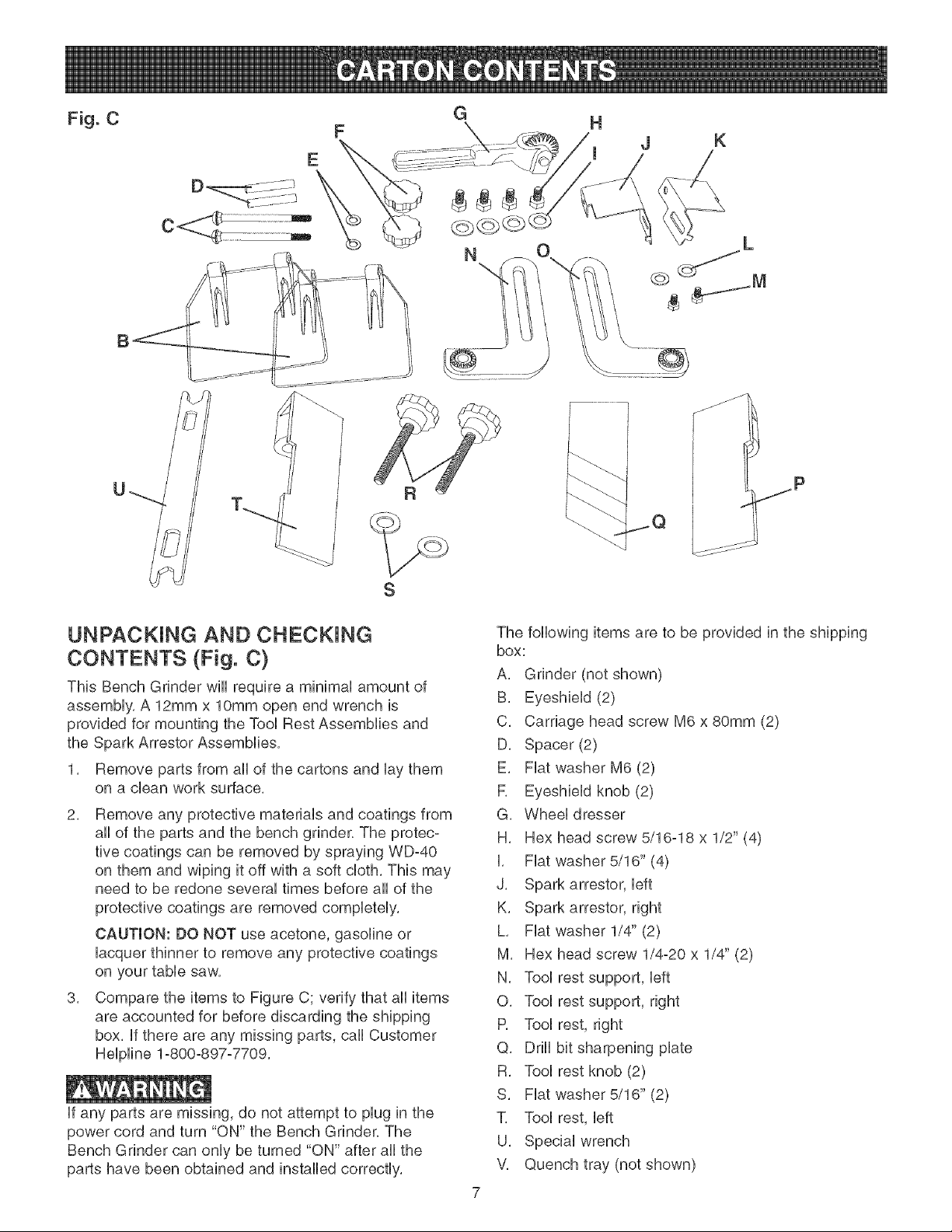
Fig. C G H
E
C .....................ZZZZ_
N
J K
U
R
S
UNPACKING AND CHECKING
CONTENTS (Fig. C)
This Bench Grinder wHUrequire a minimaU amount of
assembly, A 12mm x lOmm open end wrench is
provided for mounting the Tool Rest Assemblies and
the Spark Arrestor Assemblies,
1, Remove parts from all of the cartons and lay them
on a dean work surface,
2, Remove any protective materials and coatings from
all of the parts and the bench grinder, The protec-
tive coatings can be removed by spraying WD-40
on them and wiping it off with a soft cloth, This may
need to be redone several times before all of the
protective coatings are removed completely,
CAUTION: DO NOT use acetone, gasoline or
lacquer thinner to remove any protective coatings
on your table saw,
3, Compare the items to Figure C; verify that all items
are accounted for before discarding the shipping
box, if there are any missing parts, call Customer
Helpline 1°800-897°7709,
if any parts are missing, do not attempt to plug in the
power cord and turn "ON" the Bench Grinder, The
Bench Grinder can only be turned "ON" after all the
parts have been obtained and installed correctly,
The following items are to be provided in the shipping
box:
A, Grinder (not shown)
B, Eyeshield (2)
C, Carriage head screw M6 x 80mm (2)
D, Spacer (2)
E, Fiat washer M6 (2)
R Eyeshield knob (2)
G, Wheel dresser
H, Hex head screw 5/16-18 x 1/2" (4)
I, Fiat washer 5/16" (4)
J, Spark arrestor, left
K, Spark arrestor, right
L, Fiat washer 1/4" (2)
M, Hex head screw 1/4-20 x 1/4" (2)
N, Tool rest support, left
O, Tool rest support, right
R Tool rest, right
Q, Drill bit sharpening plate
R, Tool rest knob (2)
S, Fiat washer 5/16" (2)
1, Tool rest, left
U, Special wrench
V, Quench tray (not shown)
16
17
18
4
14
12
11
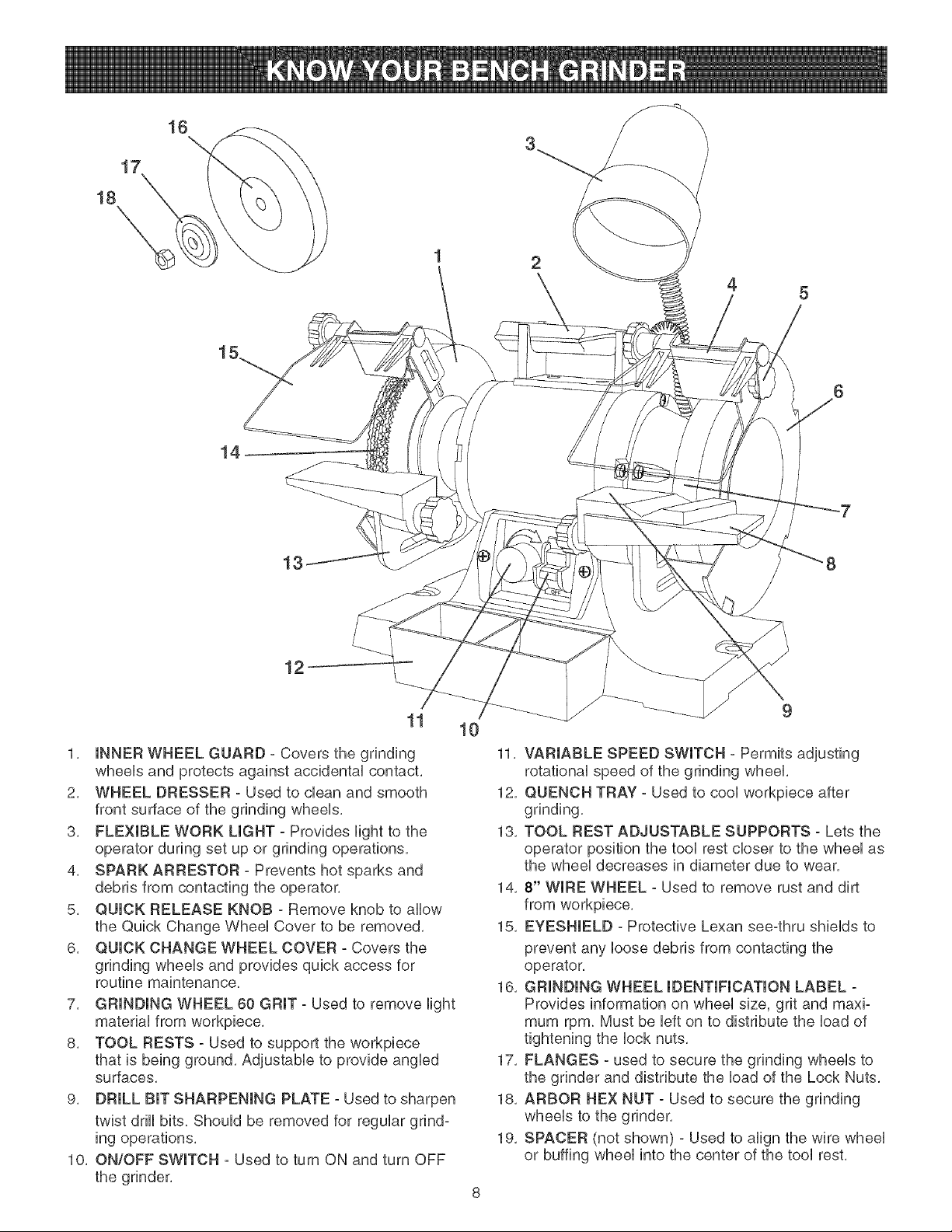
1, INNER WHEEL GUARD - Covers the grinding
wheeUs and protects against accidentaU contact,
2, WHEEL DRESSER - Used to clean and smooth
front surface of the grinding wheeUs,
3, FLEXIBLE WORK LIGHT - Provides Hght to the
operator during set up or grinding operations,
4, SPARK ARRESTOR - Prevents hot sparks and
debris from contacting the operator,
5, QUICK RELEASE KNOB - Remove knob to allow
the Quick Change WheeU Cover to be removed,
6, QUICK CHANGE WHEEL COVER - Covers the
grinding wheeUs and provides quick access for
routine maintenance,
7, GRINDING WHEEL 60 GRIT - Used to remove Hght
materiaU from workpbce,
8, TOOL RESTS - Used to support the workpbce
that is being ground, Adjustabb to provide angbd
surfaces,
9, DRILL BIT SHARPENING PLATE - Used to sharpen
twist drill bits, Should be removed for regular grind-
ing operations,
10, ON/OFF SWITCH - Used to turn ON and turn OFF
the grinder,
10
11, VARIABLE SPEED SWITCH - Permits adjusting
rotational speed of the grinding wheel,
12, QUENCH TRAY - Used to cool workpiece after
grinding,
13, TOOL REST ADJUSTABLE SUPPORTS - Lets the
operator position the tool rest closer to the wheel as
the wheel decreases in diameter due to wear,
14, 8" WIRE WHEEL - Used to remove rust and dirt
from workpiece,
15, EYESHIELD - Protective Lexan see-thru shields to
prevent any loose debris from contacting the
operator,
16, GRINDING WHEEL IDENTIFICATION LABEL -
Provides information on wheel size, grit and maxi-
mum rpm, Must be left on to distribute the load of
tightening the lock nuts,
17, FLANGES ° used to secure the grinding wheels to
the grinder and distribute the load of the Lock Nuts,
18, ARBOR HEX NUT - Used to secure the grinding
wheels to the grinder,
19, SPACER (not shown) - Used to align the wire wheel
or buffing wheel into the center of the tool rest,
TheBenchGrinderisprovidedwitha Ueftandrighttwo
pieceToolRest.BothToolRestshavea fiat,smooth
surfacetoUayyourworkpieceagainst.Anaccessory
DrHUBitSharpeningHateis included.ThispUategoes
onovertherightToolRestonUyandisusedtosharpen
twistdrHUbits.
Fig. E
E
1. DO NOT assemMe the Bench Grinder until you are
sure the tooU IS NOT pUugged in.
2. DO NOT assemMe the Bench Grinder until you are
sure the power switch is in the "OFF" position.
3. DO NOT assemMe the Bench Grinder until you are
sure the grinding wheeUs are firmUy tightened to the
Bench Grinder.
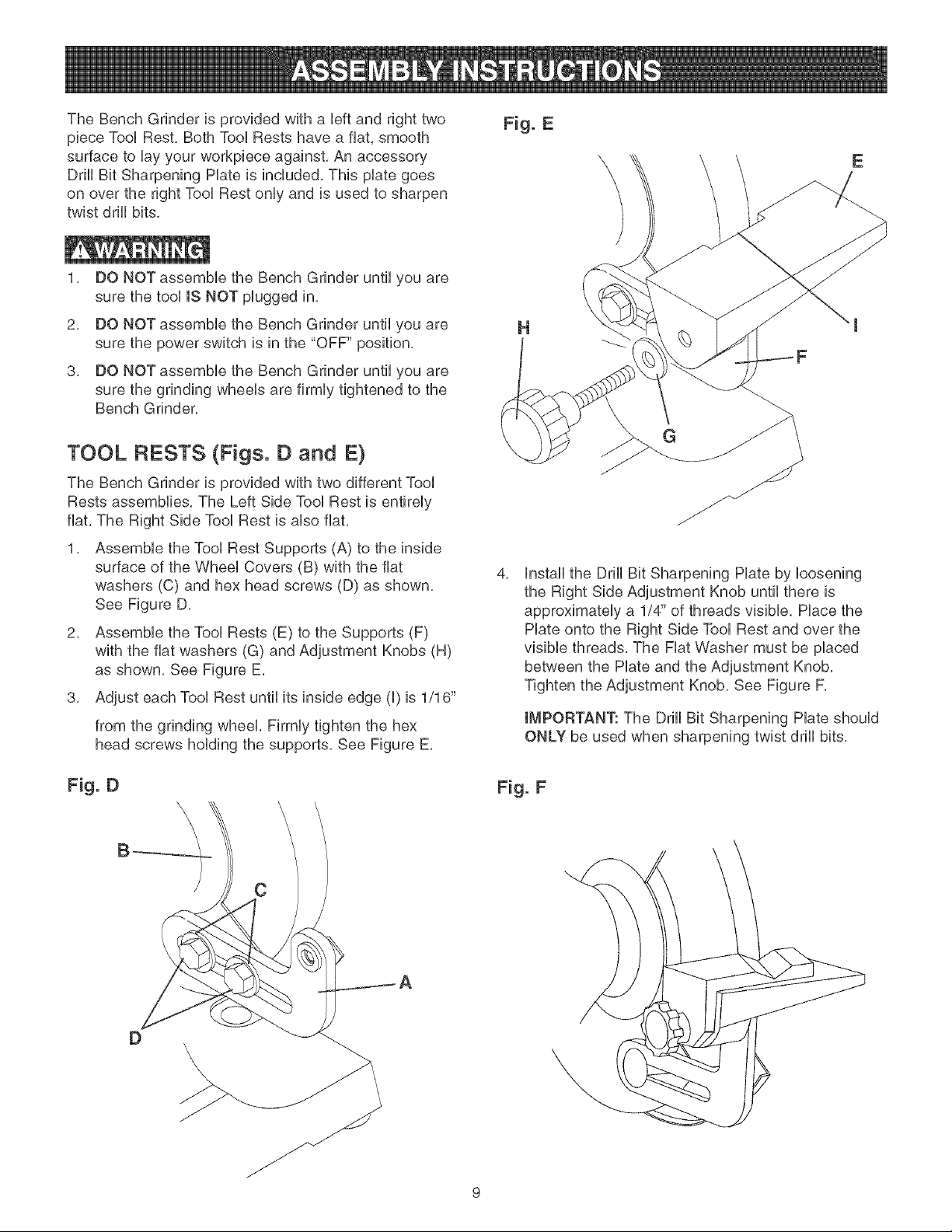
TOOL RESTS (Figs. D and E}
The Bench Grinder is provided with two different Tool
Rests assemblies. The Left Side Tool Rest is entirely
flat. The Right Side Tool Rest is also flat.
1. Assemble the Tool Rest Supports (A) to the inside
surface of the Wheel Covers (B) with the flat
washers (C) and hex head screws (D) as shown.
See Figure D.
2. Assemble the Tool Rests (E) to the Supports (F)
with the flat washers (G) and Adjustment Knobs (H)
as shown. See Figure E.
3. Adjust each Tool Rest until its inside edge (I) is 1/16"
from the grinding wheel. Firmly tighten the hex
head screws holding the supports. See Figure E.
Fig. D
B
\
\
\
C
H
4,
G
Install the Drill Bit Sharpening Plate by loosening
the Right Side Adjustment Knob until there is
approximately a 1/4" of threads visible. Place the
Plate onto the Right Side Tool Rest and over the
visible threads. The Flat Washer must be placed
between the Plate and the Adjustment Knob.
Tighten the Adjustment Knob. See Figure F.
IMPORTANT: The Drill Bit Sharpening Plate should
ONLY be used when sharpening twist drill bits.
Fig. F
D \
\
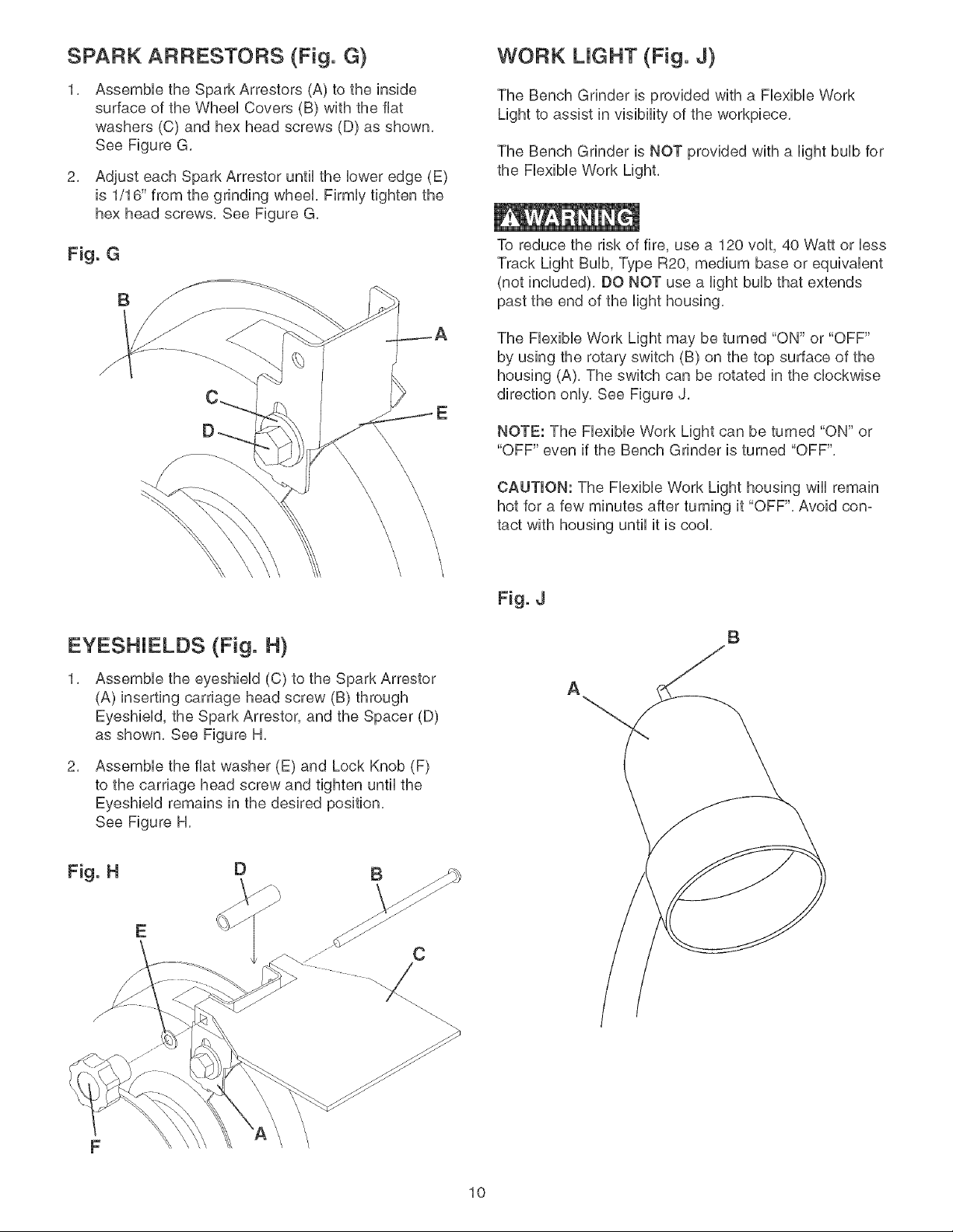
SPARK ARRESTORS (Fig. G)
Assembb the Spark Arrestors (A) to the inside
surface of the Wheel Covers (B) with the flat
washers (C) and hex head screws (D) as shown,
See Figure G,
2, Adjust each Spark Arrestor until the lower edge (E)
is 1/16" from the grinding wheel, Firmly tighten the
hex head screws, Bee Figure G,
Fig. G
B
WORK UGHT (Fig. J)
The Bench Grinder is provided with a Fbxibb Work
Light to assist in visiblity of the workpbce,
The Bench Grinder is NOT provided with a Nght bulb for
the Fbxibb Work Light,
To reduce the risk of fire, use a 120 volt, 40 VVattor less
Track Light Bulb, Type R20, medium base or equivalent
(not included), DO NOT use a light bulb that extends
past the end of the light housing,
The Flexible Work Light may be turned "ON" or "OFF"
by using the rotary switch (B) on the top surface of the
housing (A), The switch can be rotated in the clockwise
direction only, See Figure J,
NOTE: The Flexible Work Light can be turned "ON" or
"OFF" even if the Bench Grinder is turned "OFF",
CAUTION: The Flexible Work Light housing wiii remain
hot for a few minutes after turning it "OFF", Avoid con-
tact with housing until it is cool,
EYESHIELDS (Fig. H)
Assemble the eyeshield (C) to the Spark Arrestor
(A) inserting carriage head screw (B) through
Eyeshield, the Spark Arrestor, and the Spacer (D)
as shown, Bee Figure H,
2,
Assemble the fiat washer (E) and Lock Knob (F)
to the carriage head screw and tighten until the
Eyeshield remains in the desired position,
See Figure H,
E
Fig. J
A
B
10
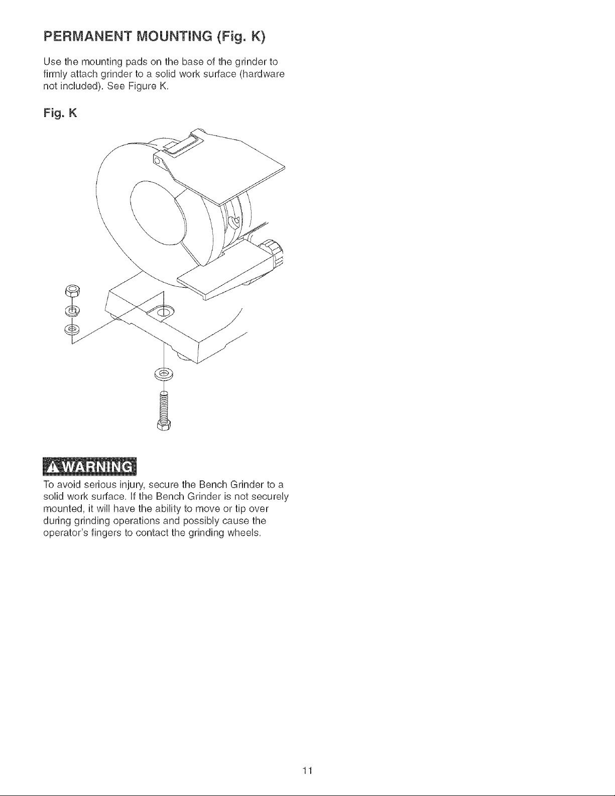
PERMANENT MOUNTING (Fig. K)
Use the mounting pads on the base of the grinder to
firmUyattach grinder to a solid work surface (hardware
not included), See Figure K,
Fig. K
To avoid serious injury, secure the Bench Grinder to a
solid work surface, ff the Bench Grinder is not secureUy
mounted, it wHUhave the ability to move or tip over
during grinding operations and possiMy cause the
operator's fingers to contact the grinding wheeUs,
11
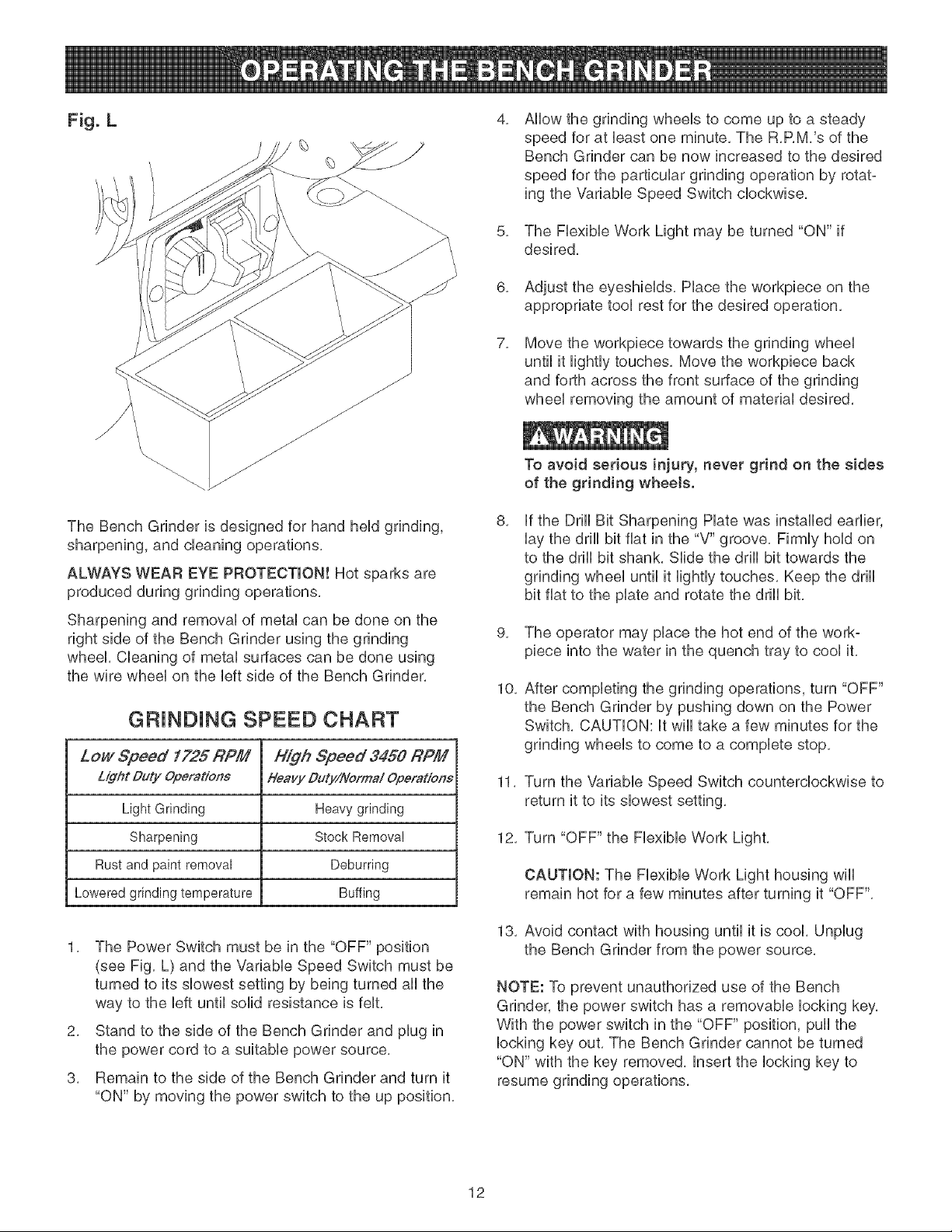
Fig. L
The Bench Grinder is designed for hand held grinding,
sharpening, and cleaning operations,
ALWAYS WEAR EYE PROTECTION! Hot sparks are
produced during grinding operations,
Sharpening and removai of metai can be done on the
right side of the Bench Grinder using the grinding
wheel Cieaning of metai surfaces can be done using
the wire wheei on the Heftside of the Bench Grinder,
GRiNDiNG SPEED CHART
Low Speed 1725 RPf# High Speed 3450 RPf/I
Light Duty Operations Heavy Duty/Norma/ Operations
Light Grinding Heavygrinding
Sharpening Stock Removal
Rust and paint removal Deburring
Loweredgrindingtemperature Buffing
1, The Power Switch must be in the "OFF" position
(see Fig, L) and the VariabHe Speed Switch must be
turned to its slowest setting by being turned all the
way to the Heftuntil solid resistance is feit,
2, Stand to the side of the Bench Grinder and piug in
the power cord to a suitable power source,
3, Remain to the side of the Bench Grinder and turn it
"ON" by moving the power switch to the up position,
4,
5,
6,
7,
Ailow the grinding wheeis to come up to a steady
speed for at bast one minute, The R,RM,'s of the
Bench Grinder can be now increased to the desired
speed for the particular grinding operation by rotat-
ing the Variabie Speed Switch ciockwise,
The Fiexibie Work Light may be turned "ON" if
desired,
Adjust the eyeshieids, Piace the workpiece on the
appropriate tool rest for the desired operation,
Move the workpiece towards the grinding wheel
until it lightly touches, Move the workpiece back
and forth across the front surface of the grinding
wheel removing the amount of material desired,
To avoid serious injury, never grind on the sides
of the grinding wheels.
8,
if the Drill Bit Sharpening Hate was installed earlier,
lay the drill bit fiat in the "V" groove, Firmly hold on
to the drill bit shank, Slide the drill bit towards the
grinding wheel until it lightly touches, Keep the drill
bit fiat to the plate and rotate the drill bit,
9, The operator may place the hot end of the work°
piece into the water in the quench tray to cool it,
10,
After completing the grinding operations, turn "OFF"
the Bench Grinder by pushing down on the Power
Switch, CAUTION: it will take a few minutes for the
grinding wheels to come to a complete stop,
11, Turn the Variable Speed Switch counterclockwise to
return it to its slowest setting,
12, Turn "OFF" the Flexible Work Light,
CAUTION: The Flexible Work Light housing wiii
remain hot for a few minutes after turning it "OFF",
13, Avoid contact with housing until it is cool, Unplug
the Bench Grinder from the power source,
NOTE: To prevent unauthorized use of the Bench
Grinder, the power switch has a removable locking key,
With the power switch in the "OFF" position, pull the
locking key out, The Bench Grinder cannot be turned
"ON" with the key removed, insert the locking key to
resume grinding operations,
12
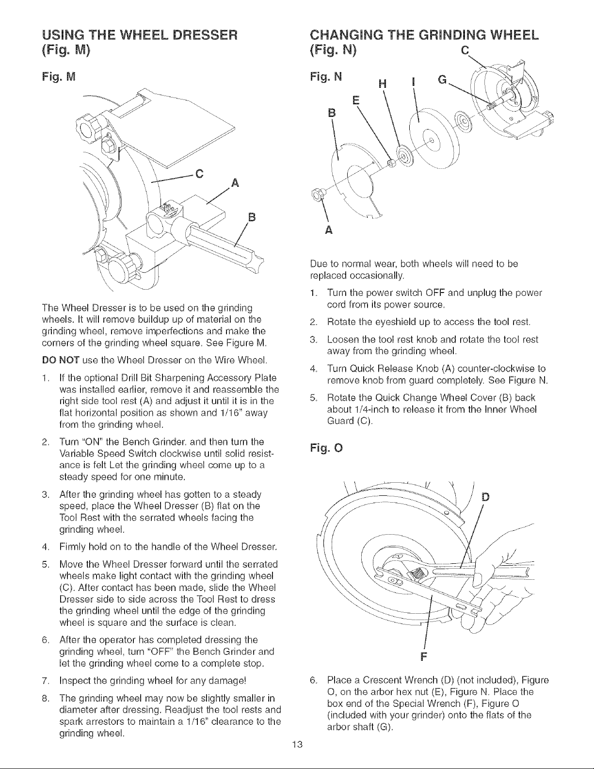
USING THE WHEEL DRESSER
(Fig. M)
Fig. M
B
The Wheel Dresser is to be used on the grinding
wheels, it wiii remove buildup up of material on the
grinding wheel, remove imperfections and make the
corners of the grinding wheel square, See Figure M,
DO NOT use the Wheel Dresser on the Wire Wheel,
1, if the optional Drill Bit Sharpening Accessory Hate
was installed earlier, remove it and reassemble the
right side tool rest (A) and adjust it until it is in the
fiat horizontal position as shown and 1/16" away
from the grinding wheel,
2, Turn "ON" the Bench Grinder, and then turn the
Variable Speed Switch clockwise until solid resist°
ance is felt Let the grinding wheel come up to a
steady speed for one minute,
3, After the grinding wheel has gotten to a steady
speed, place the Wheel Dresser (B) fiat on the
Tool Rest with the serrated wheels facing the
grinding wheel,
4, Firmly hold on to the handle of the Wheel Dresser,
5, Move the Wheel Dresser forward until the serrated
wheels make light contact with the grinding wheel
(C), After contact has been made, slide the Wheel
Dresser side to side across the Tool Rest to dress
the grinding wheel until the edge of the grinding
wheel is square and the surface is clean,
6, After the operator has completed dressing the
grinding wheel, turn "OFF" the Bench Grinder and
let the grinding wheel come to a complete stop,
7, inspect the grinding wheel for any damage!
8, The grinding wheel may now be slightly smaller in
diameter after dressing, Readjust the tool rests and
spark arrestors to maintain a 1/16" clearance to the
grinding wheel,
13
CHANGING THE GF{JNDJNG WHEEL
(Fig. N) C
B
A
Due to normal wear, both wheels will need to be
replaced occasionally,
1, Turn the power switch OFF and unplug the power
cord from its power source,
2, Rotate the eyeshield up to access the tool rest,
3, Loosen the tool rest knob and rotate the tool rest
away from the grinding wheel,
4, Turn Quick Release Knob (A) counter-clockwise to
remove knob from guard completely, See Figure N,
5, Rotate the Quick Change Wheel Cover (B) back
about 1/4°inch to release it from the inner Wheel
Guard (C),
Fig. O
D
6,
Place a Crescent Wrench (D) (not included), Figure
O, on the arbor hex nut (E), Figure N, Place the
box end of the Special Wrench (F), Figure 0
(included with your grinder) onto the fiats of the
arbor shaft (G),
7,
5,
9,
NOTE: The left hand arbor hex nut is left hand
threaded and is loosened by rotating it clockwise.
The right hand arbor hex nut is right hand threaded
and is loosened by rotating it counter-clockwise.
Remove the Outer Wheel Flange (H) and then the
abrasive wheel (I) from the arbor shaft.
CAUTION: The new abrasive wheel to be put onto
the grinder must have a higher R.P.M. rating than
the grinder (3450 R.RM.). The new abrasive wheel
must have the correct outer wheel diameter and
bore diameter as original wheels. The label on the
side of the abrasive wheel must stay on. DO NOT
remove this label.
10. Replace the abrasive wheel, outer wheel flange and
arbor hex nut. NOTE: The left hand arbor hex nut is
left hand threaded and is tightened by rotating it
counter-clockwise. The right hand arbor hex nut is
right hand threaded and is tightened by rotating it
clockwise.
CAUTION: DO NOT OVER-TIGHTEN the arbor hex
nut as this may damage the abrasive wheel and
cause serious injury to the operator,
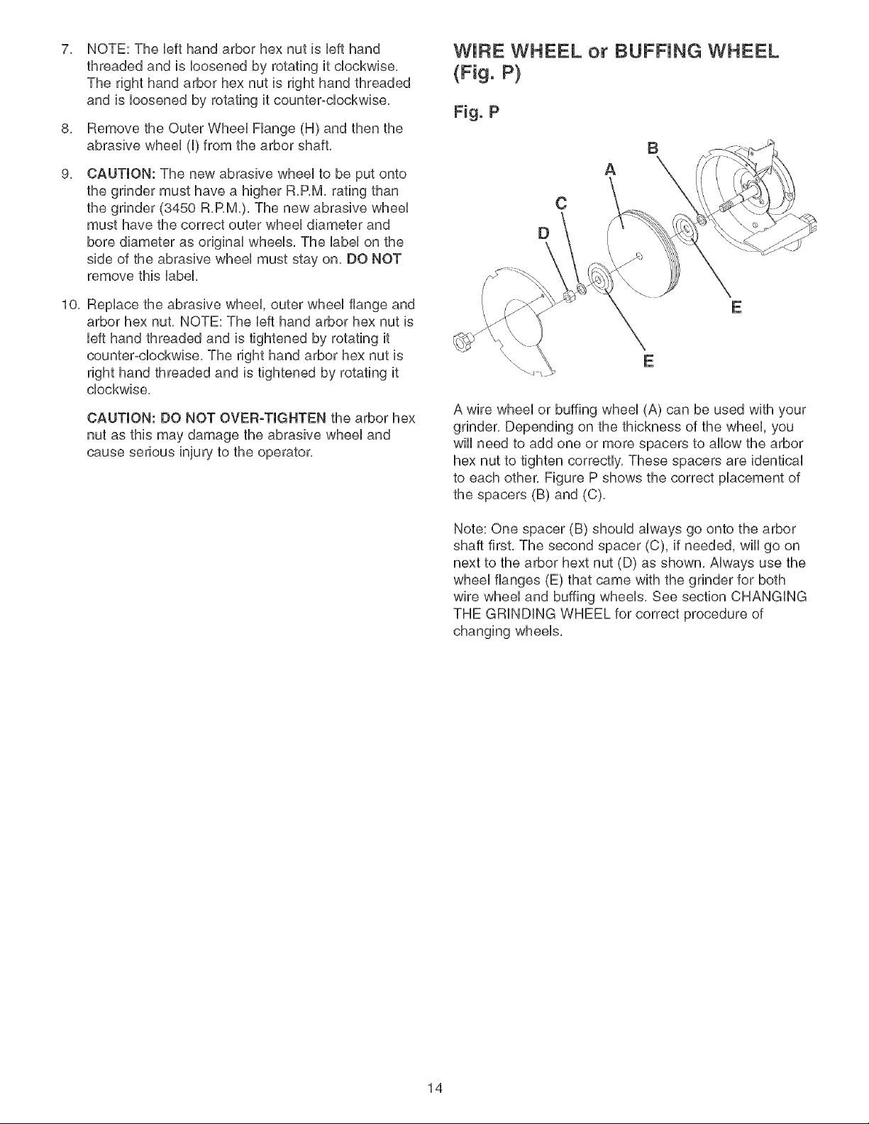
WIF{E WHEEL or BUFNNG WHEEL
B
A
E
E
A wire wheel or buffing wheel (A) can be used with your
grinder. Depending on the thickness of the wheel, you
wiii need to add one or more spacers to allow the arbor
hex nut to tighten correctly. These spacers are identical
to each other. Figure P shows the correct placement of
the spacers (B) and (C).
Note: One spacer (B) should always go onto the arbor
shaft first. The second spacer (C), if needed, wiii go on
next to the arbor hext nut (D) as shown. Always use the
wheel flanges (E) that came with the grinder for both
wire wheel and buffing wheels. See section CHANGING
THE GRiNDiNG WHEEL for correct procedure of
changing wheels.
14
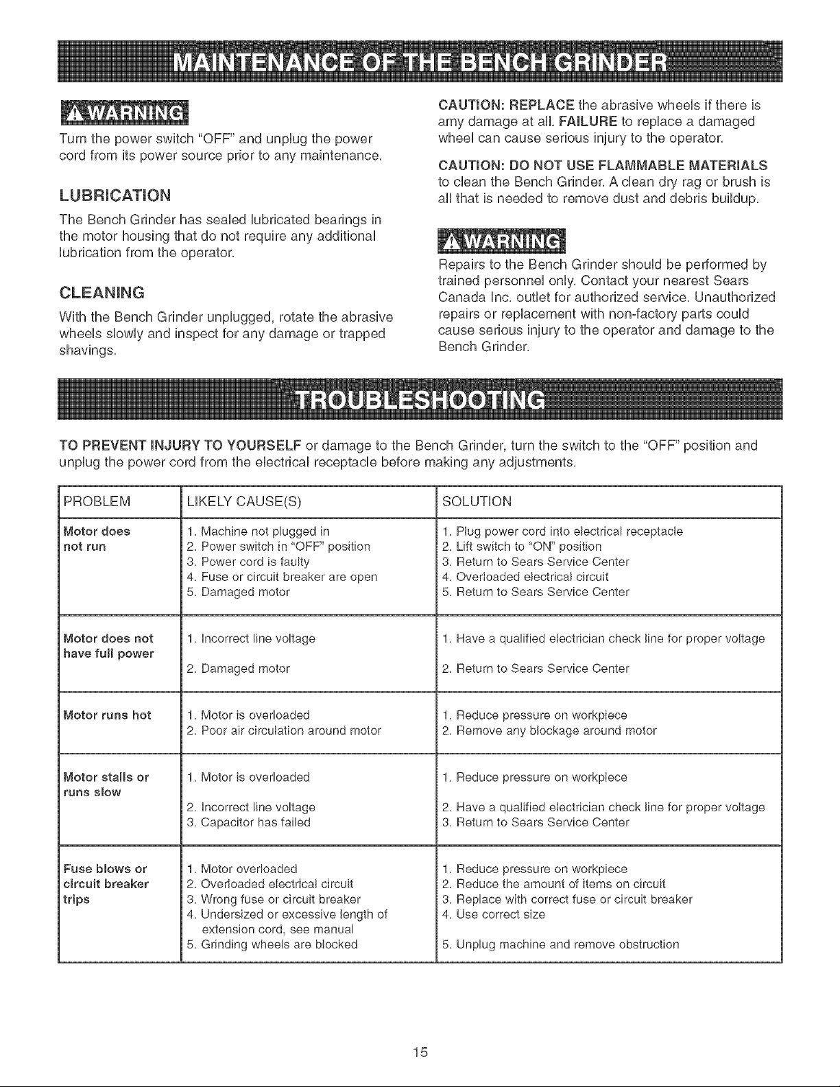
Turnthepowerswitch"OFF"andunplugthepower
cordfromitspowersourcepriortoanymaintenance,
LUBRiCATiON
The Bench Grinder has seabd Uubdcated bearings in
the motor housing that do not require any additionaU
Uubdcation from the operator,
CLEANING
With the Bench Grinder unpUugged, rotate the abrasive
wheeUs sbwUy and inspect for any damage or trapped
shavings,
CAUTION: REPLACE the abrasive wheeUs if there is
amy damage at all, FAILURE to repUace a damaged
wheeUcan cause serious injury to the operator,
CAUTION: DO NOT USE FLAMMABLE MATERIALS
to clean the Bench Grinder, A clean dry rag or brush is
aH that is needed to remove dust and debris buildup,
Repairs to the Bench Grinder shoWd be performed by
trained personneU onUy,Contact your nearest Sears
Canada Unc,outlet for authorized servbe, Unauthorized
repairs or replacement with non-factory parts could
cause serious injury to the operator and damage to the
Bench Grinder,
TO PREVENT INJURY TO YOURSELF or damage to the Bench Grinder, turn the switch to the "OFF" position and
unplug the power cord from the electrical receptacle before making any adjustments,
PROBLEM
Motor does
not run
Motor does not
have full power
Motor runs hot
Motor stalls or
runs S_OW
Fuse blows or
circuit breaker
trips
LIKELY CAUSE(S) SOLUTION
1. Machine not plugged in
2. Power switch in "OFF" position
3. Power cord is faulty
4. Fuse or circuit breaker are open
5. Damaged motor
1. Incorrect line voltage
2. Damaged motor
1. Motor is overloaded
2. Poor air circulation around motor
1. Motor is overloaded
2. Incorrect line voltage
3. Capacitor has failed
1. Motor overloaded
2. Overloaded electrical circuit
3. Wrong fuse or circuit breaker
4. Undersized or excessive length of
extension cord, see manual
5. Grinding wheels are blocked
1. Plug power cord into electrical receptacle
2. Lift switch to "ON" position
3. Return to Sears Service Center
4. Overloaded electrical circuit
5. Return to Sears Service Center
1. Have a qualified electrician check line for proper voltage
2. Return to Sears Service Center
1. Reduce pressure on workpiece
2. Remove any blockage around motor
1. Reduce pressure on workpiece
2. Have a qualified electrician check line for proper voltage
3. Return to Sears Service Center
1. Reduce pressure on workpiece
2. Reduce the amount of items on circuit
3. Replace with correct fuse or circuit breaker
4. Use correct size
5. Unplug machine and remove obstruction
15

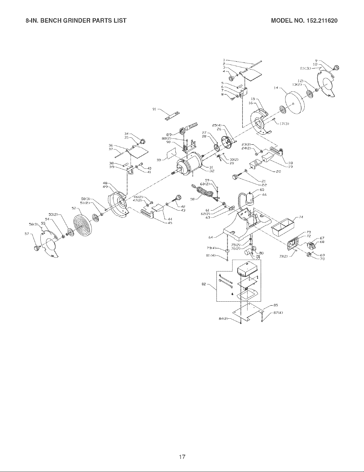
84N.BENCHGRmNDERPARTSUST MODELNO.152.211620
Whenservicing,useonlyCRAFTSMANreplacementparts,Useof anyotherpartsmaycreatea HAZARDorcause
productdamage,
Anyattemptto repairor replaceelectricalpartsonthisDustCollectormaycreatea HAZARDunlessrepairisdoneby
aqualifiedservicetechnician,Repairserviceisavailableat yournearestSearsServiceCenter,
Alwaysorderby PARTNUMBER,notbykeynumber,
KEY PART KEY PART
NO. NO. DESCRiPTiON QTY. NO. NO.
1 OR90055 CARRIAGE HEAD SCREW M6 x 80mm 1 40 STD523105
2 OR90152 EYESHELD 1 47 STD551031
3 STD851000 FLAT WASHER M6 1 48 OR90007
4 OR90001 KNOB M6 1 49 OR93207
5 OR90002 SPACER 1 50 STD5!2505
6 OR90003 SPARK ARRESTOR R.H. 1 51 OR90424
7 STD55!012 FLAT WASHER 1/4" 1 52 OR93655
8 OR90!50 HEX HEAD SCREW 1/4-20 x 1/4" 1 53 0R90188
9 OR93190 KNOB 1 54 0R90372
10 OR93202 COVER QUICK RELEASE R.H. 1 55 0R93208
11 OR93192 BUSHING 3 56 0R93192
12 OR90370 HEX NUT UNC 5/8"-1!, R.H. 1 57 0R93190
13 OR90188 FLANGE 2 58 OR90207
14 OR90189 8" GRINDING WHEEL 60 GRIT, 59 STD511002
8" Diameter x 1" Wide x 5/8" Bore I 60 0R90053
15 OR93203 WHEEL GUARD, QUICK RELEASE R.H. 1 61 0R900!7
16 OR90007 ROTATION LABEL 1 62 STD511002
17 STD512505 TRUSS HEAD SCREW 1/4-24 x 1/2" 3 63 OR90031
18 OR90!9! TOOL REST SUPPORT, R.H. 1 64 OR90209
19 OR90!92 TOOL REST, R.H. 1 65 OR902!0
20 OR91093 DRILL BIT SHARPENING PLATE 1 66 OR91317
21 STD55!031 FLAT WASHER 5/16" 1 67 OR90037
22 OR90155 KNOB 5/10-18 1 68 OR90038
23 STD55!031 FLAT WASHER 5/16" 2 69 OR90056
24 STD523105 HEX HEAD SCREW 5/!0-18 x 1/2" 2 70 OR90039
25 OR9365! TRUSS HEAD SCREW #10-24 x 5/8" 4 71 STD5!1003
26 OR93652 END BELL, R.H. 1 72 OR90036
27 OR93653 PAN HEAD SET SCREW M5 x 5ram 1 73 OR90035
28 OR90013 PLATE 1 74 OR90040
29 OR90014 SENSOR ASSY 1 75 STD551125
30 OR90057 PAN HEAD SCREW M3 x 6ram 2 76 STD541025
31 OR93654 MOTOR ASSEMBLY. 8" V.S. GRINDER 1 77 OR93657
32 OR93659 NAMEPLATE 1 78 STD5!1003
33 OR93660 SPEC PLATE 1 79 OR90045
34 OR9000! KNOB M6 1 80 OR93661
35 STD85!006 FLAT WASHER M6 1 81 STD5!1003
36 OR90152 EYESHELD 1 82 OR93658
37 OR90055 CARRIAGE HEAD SCREW M6 x 80ram 1 84 OR90054
38 OR90002 SPACER 1 85 OR90044
39 OR90025 SPARK ARRESTOR LH. 1 87 STD5!1003
40 OR90!50 HEX HEAD SCREW 1/4-20 x 1/4" 1 88 STD511002
41 STD55!012 FLAT WASHER 1/4" 1 89 OR90049
42 OR90155 KNOB 5/10-!8 1 90 OR902!2
43 STD55!031 FLAT WASHER 5/16" 1 91 OR93199
44 OR90204 TOOL REST, LH. 1 N/A OR93650
45 OR90203 TOOL REST SUPPORT, L.H 1
DESCRiPTiON QTY.
HEX HEAD SCREW 5/16-18 x 1/2" 2
FLAT WASHER 5/16" 2
ROTATION LABEL 1
WHEEL GUARD, QUICK RELEASE, L.H. 1
TRUSS HEAD SCREW 1/4-24 x 1/2" 3
SPACER 5/8" BORE 2
8" WIRE WHEEL, 8" DIAMETER x 5/8" BORE 1
FLANGE 2
HEX NUT UNC 5/8"ql LH. 1
COVER, QUICK RELEASE L.H." 1
BUSHING 3
KNOB 1
POWER CORD 1
TRUSS HEAD SCREW #10-24 x 1/4" 1
EXT TOOTH WASHER #!0 2
STRAIN RELIEF<6N-4> 1
TRUSS HEAD SCREW #!0-24 x 1/4" 2
CORD MOUNTING PLATE 1
BASE 1
LIGHT ASSEMBLY 1
WARNING LABEL 1
SWITCH, INCLUDES SWITCH KEY 1
SWITCH KEY 1
SLOTTED SET SCREW M4 x 6mm 1
KNOB 1
TRUSS HEAD SCREW #!0-24 x 3/8" 2
VARIABLE SPEED LABEL 1
SWITCH PLATE 1
QUENCH TRAY 1
LOCK WASHER 1/4" 2
HEX NUT 1/4-20 2
CAPACITOR<60uf 250V.AC> 1
TRUSS HEAD SCREW #10-24 x 3/8" 1
PAD 4
CAPACITOR CLAMP 1
TRUSS HEAD SCREW #10-24 x 3/8" 4
CIRCUIT BOARD ASSY 1
PAN HEAD TAP SCREW M4 x 8ram 2
COVER PLATE 1
TRUSS HEAD SCREW #!0-24 x 3/8" 4
TRUSS HEAD SCREW #10-24 x 1/4" 2
WHEEL DRESSER 1
SUPPORT 1
SPECIAL WRENCH 1
INSTRUCTION MANUAL #21162 1
16
84N.BENCHGRmNDERPARTSUST MODELNO.152.211620
26
63
45
19
20
17

18
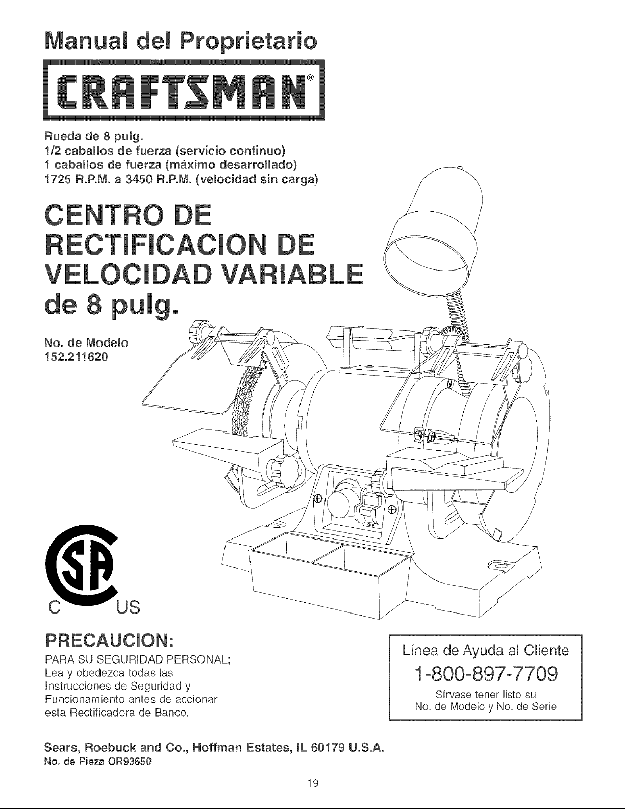
anual Proprietario
®
Rueda de 8 pu_g.
1/2 caballos de fuerza (servicio continuo)
I cabalJos de fuerza (ma×imo desarroHado)
1725 R.PoM. a 3450 R.PoM. (ve_ocidad sin carga)
CE O
c_us
PRECAUCION:
PARA SU SEGURIDAD PERSONAL;
Lea y obedezca todas Ras
tnstrucciones de Seguddad y
Funcionamiento antes de accionar
esta Rectificadora de Banco.
Lfnea de Ayuda al Cliente
1-800-897-7709
Sirvase tenet listo su
No. de Modelo y No. de Sede
Sears, Roebuck and Co., Hoffman Estates, IL 60179 U.S.A.
No. de Pieza OR93650
19
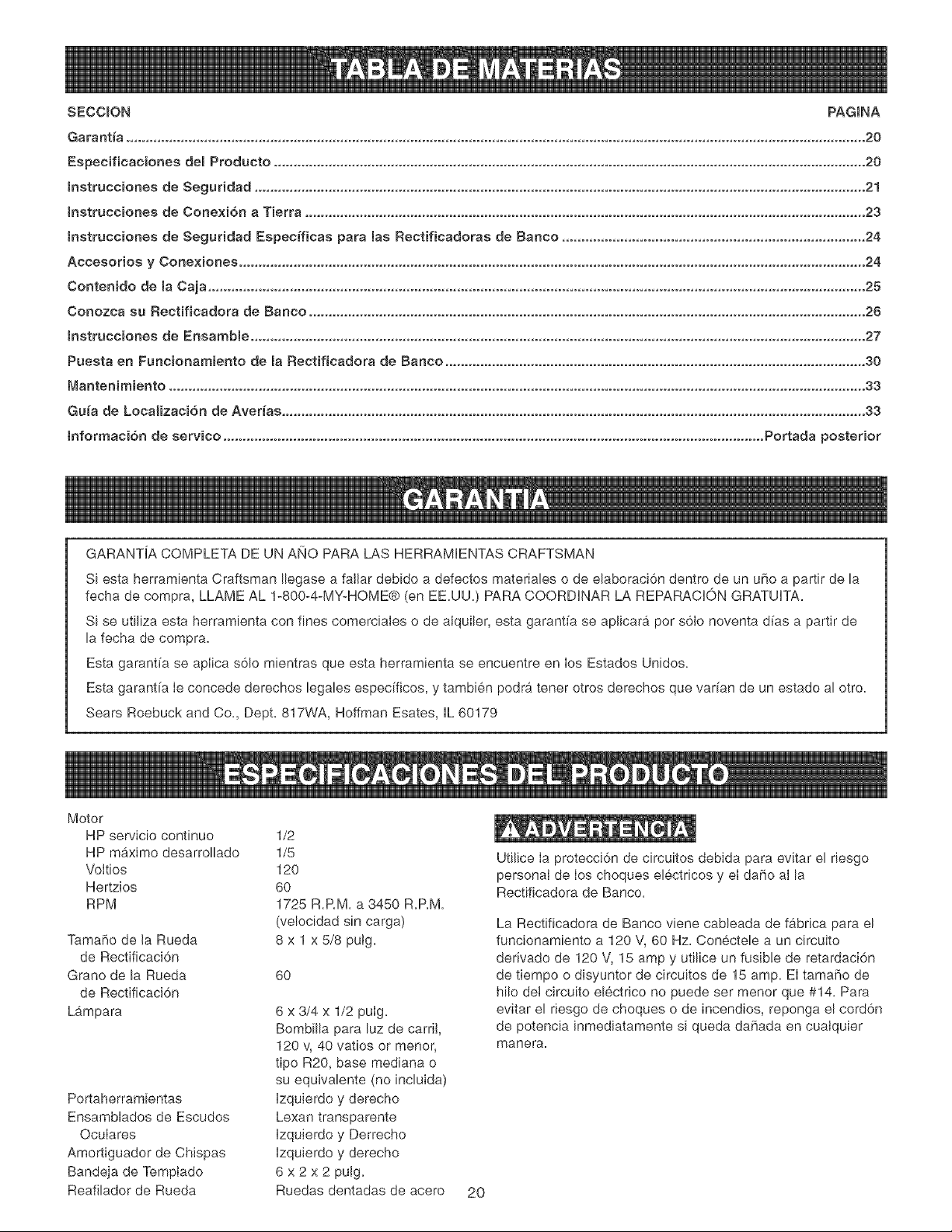
SECCION PAGINA
Garantia .............................................................................................................................................................................................. 20
Especificaciones deB Producto ........................................................................................................................................................ 20
tnstruce}ones de Segaddad ............................................................................................................................................................. 21
tnstrucc}ones de Conexion a Tierra ................................................................................................................................................ 23
tnstrucciones de Segaddad Especfficas para las Rectificadoras de Banco .............................................................................. 24
Acceeeriee y Cone×}ones ................................................................................................................................................................. 24
Conten}de de la Caja ......................................................................................................................................................................... 25
Conozca su Rectifieadera de Baneo ............................................................................................................................................... 26
tnstrucc}ones de Ensamble .............................................................................................................................................................. 27
Pueeta en Fancionamiente de la Rectifieadora de Banco ............................................................................................................ 30
Manten{miento ................................................................................................................................................................................... 33
Gala de Local}zac}6n de Aver_as ...................................................................................................................................................... 33
tnfermacibn de serv}co ........................................................................................................................................... Portada posterior
GARANTiA COMPLETA DE UN ANO PARA LAS HERRAMIENTAS CRAFTSMAN
Si esta herramienta Craftsman Ilegase a fallar debido a defectos materiales o de elaboraci6n dentro de un uho a partir de la
fecha de compra, LLAME AL 1-800-4-MY-HQME@ (en EE.UU.) PARA CQQRDINAR LA REPARACIC}N GRATUITA.
Si se utiliza esta herramienta con fines comerciaIes o de alquiler, esta garantfa se aplicara por s61o noventa d[as a partir de
la fecha de compra.
Esta garantfa se apliea s61o mientras que esta herramienta se encuentre en los Estados Unidos.
Esta garantfa Ie concede derechos legales especificos, y tambien podra tener otros derechos que varfan de un estado al otro.
Sears Roebuck and Co., Dept. 817WA, Hoffman Esates, iL 60179
Motor
HP servicio continuo 1/2
HP maximo desarrolbdo 1/5
Vottios 120
Hertzios 60
RPM 1725 R.RM. a 3450 R.P.M.
(velocidad sin carga)
TamaRo de la Rueda 8 x 1 x 5/8 putg.
de Rectificaci6n
Grano de la Rueda 60
de Rectificaci6n
Lampara 6 x 3/4 x 1/2 puIg.
Bombilb para luz de carril,
120 v, 40 vatios or menor,
tipo R20, base mediana o
su equivalente (no incluida)
Izquierdo y derecho
Lexan transparente
Izquierdo y Derrecho
Izquierdo y derecho
6x2x2pulg.
Ruedas dentadas de acero
Portaherramientas
Ensamblados de Escudos
Oculares
Amortiguador de Chispas
Bandeja de Temptado
Reafilador de Rueda
2O
Utilice Ia protecci6n de circuitos debida para evitar el riesgo
personal de los choques electricos y el daho aIla
Rectificadora de Banco.
La Rectificadora de Banco viene cableada de fabrica para el
funcionamiento a 120 V, 60 Hz. Conectele a un circuito
derivado de 120 V, 15 amp y utilice un fusible de retardaci6n
de tiempo o disyuntor de circuitos de 15 amp. El tama_o de
hilo de! circuito electrico no puede set menor que #14. Para
evitar el riesgo de choques o de incendios, reponga el cord6n
de potencia inmediatamente si queda dahada en cualquier
manera.

INSTRUCCIONES GENERALES
DE SEGUF{JDAD
El funcionamiento de una Rectificadora de Banco puede
resuJtar pelJgroso si se hace case omiso de la seguridad y del
sentido com0n. EJ operarJo debe estar famJIiarizado con el
funcionamiento de la herramienta. Lea este manual para
entender su Rectificadora de Banco. NO OPERE esta
Rectificadora de Banco si no entiende a cabalidad las Iimi-
taciones de dicha herramienta. NO reaJice modificaciones de
cualquier tipo a esta Rectificadora de Banco.
ANTES DE UTmLmZAR
LA RECTIFICADORA DE BANCO
Para evitar las heridas graves y ei da_o a la herramienta, Iea
y obedezca todas Ias Instrucciones de Seguridad y Operaci6n
antes de operar Ja Rectificadora de Banco.
1. LEA a consciencia el Manual del Propietario.
APRENDA c6mo hacer use de esta herramienta para
sus apJicaciones disehadas.
2, CONECTE TODAS LAS HERRAMIENTAS A TJERRA,
Si la herramienta se suministra con un enchufe de 3
machos, se le debe enchufar a un tomacorrientes que
disponga de 3 contactos electricos. El tercer macho se
utiliza para conectar Ia herramJenta a tierra y ofrecer pro-
tecci6n contra los choques eI6.ctricos accidentales. NO
quite eJ tercer macho. Vea las Instrucciones de Conexi6n
a Tierra en la pb.gina 20.
3. EVITE UN ENTORNO LABORAL PELIGROSOo NO
utilice las herramientas el6ctricas en un entorno h0medo,
ni tampoco las exponga a Iluvia.
4. NO utJlice herramientas electdcas si hay gases o I[quidos
infiamables presentes.
5,
6,
MANTENGA SIEMPRE su zona de trabajo iimpia, bJen
alumbrada y organizada. NO TRABAJE en un entorno
con superficies de piso resbalosas a consecuencia de Jos
escombros, la grasa y Ja cera.
MANTENGA ALEJADOS A LOS NINOS Y VISITANTES°
NO permJta que haya personas en Ia zona inmediata de
trabajo, particularmente cuando Ia herramienta el6ctdca
se encuentre en funcionamiento.
7,
NO FUERCE LA HERRAI'vIIENTA a realizar operaciones
para las cuales no fue disehada. Realizara una labor mas
segura y de mejor calidad si se Ie utiliza para realizar
operaciones para Jas cuales fue diseSadas.
8,
UTILiCE VESTJMENTA APROPIADA, NO vista ropa
hoigada, guantes, corbatas nJartfculos de joyerfa. Estos
art[cu!os pueden quedar atrapados en la maquina
durante las operaciones y tirar del operario, atrayendoio
hacia las piezas en movimiento. El usuario debe Ilevar
una cubierta protectiva sobre eI cabeIIo, si tiene cabeJlera
larga, para impedir el contacto con cuaIquier pieza en
movimiento.
g,
10.
11.
12.
13.
14.
15.
16.
17.
18.
19.
20.
21.
HAGA SU TALLER A PRUEBA DE NINOS aJ quitar Ias
Ilaves de los interruptores, desenchufando Ias herramien-
tas de sus tomacorrientes y usando candados.
NO utilice herramientas eIectricas en Ja presencia de
I[quidos o gases inflamables.
SIEMPRE DESENCHUFE LA HERRAMIENTA DEL
TOMACORRJENTES cuando vaya a realizar ajustes,
cambiar piezas o realizar cualquier cJase de manteni-
miento.
MANTENGA LOS ESCUDOS DE PROTECCJON EN SU
SJT_O Y EN BUEN ESTADO DE FUNC_ONAM_ENTO.
EVITE EL ARRANQUE ACCIDENTAL Aseg0rese de
que el interruptor de potencia se encuentre en la posici6n
de "APAGADO" antes de enchufar el cord6n de potencia
en el tomacorrientes.
QUITE TODAS LAS HERRAMIENTAS DE MANTENI-
MJENTO de la zona inmediata antes de encender Ja
rectificadora de banco.
SOLO UTIL_CE ACCESOR_OS DE RECOMENDADOS.
El uso de accesorios incorrectos o inapropriados puede
ocasionar heridas graves al operario y ocasionar daRo a
la herramienta. Si tiene dudas, consuite e! manuaJ de
instrucciones que se adjunta con eJaccesorio especifico.
JAMAS DEJE UNA HERRA_,_IENTA EN FUNCIONA-
MiENTO SIN ATENDER. Conmute el interruptor de
energia a Ia posicJ6n de apagado. NO abandone la
herramienta hasta que esta se haya detenido per
complete.
NO SE PARE SOBRE LA HERRAMIENTA. Pueden
producJrse heridas graves si la herramienta se vuelca
o si usted hace contacto con la herramienta acciden-
talmente.
NO ALMACENE nada por encima ni cerca de Ia m_.quina
en donde alguien pueda intentar pararse en la herra-
mienta para alcanzarlo.
MANTENGA SU EQUILIBRIO. NO se extienda sobre Ia
herramienta. Haga use de zapatos con suela de caucho
resistente aJaceite. Mantenga eJ piso libre de escombros,
grasa, o cera.
MANTENGA SUS HERRAMJENTAS CUJDADOSA-
MENTE, Mantenga sus herramientas Iimpias yen buen
estado. Mantenga afiladas todas la hojas y brocas.
REVISE St HAY PtEZAS DANADAS ANTES DE CADA
USO DE LA HERRAFvIIENTA. Revise todos los protec-
tores cuidadosamente para comprobar que funcionan
correctamente y que no estan dafiados, y que realizan
sus funciones disefladas correctamente. Revise el alinea-
miento, la fijaci6n o la ruptura de Ias piezas en movimien-
to. Cualquier protector u otra pieza que se encuentre
dahada debe repararse o reemplazarse inmediatamente.
GUARDE ESTAS INSTRUCCIONES.
21
22, HAGA SU TALLER A PRUEBA DE NINOS quitando las
IJaves de! interruptor, deeenchufando Ias herramientas de
los tomacorrientes y mediante el uso de candados,
23, NO OPERE LA HERRAMiENTA BAJO LA INFLUENCiA
DE LAS DROGAS O DEL ALCOHOL,
24. AFIANCE TODO EL MATERIAL Siempre que resuke
posible, utilice abrazaderas o pbntilIas para asegurar el
material. Esto ofrece mayor seguridad que intentar
sujetar el material con sus propias manos.
25, MANTE_NGASE ALERTA, F{JESE EN LO QUE ESTA
HACtENDO Y UTiLtCE SENTIDO COMON CUANDO
VAYA A OPERAR UNA HERRAMIENTA MEC,4N_CA,
NO UTIUCE UNA HERRAMIENTA CUANDO SE
ENCUENTRE CANSADO O BAJO LA tNFLUENCIA DE
DROGAS, ALCOHOL O MEDICAMENTOS. Un momen-
to de descuido durante la operacJ6n de las herrambntas
mecanbas puede resultar en heridas personales graves.
26. UTILICE StEMPRE UNA CARETA DE POLVO PARA
IMPEDIR LA ASPIRACI6N DE POLVO PEUGROSO O
PARTICULAS AEREAS induyendo poivo de madera,
potvo de sflice cristalina y polvo de asbesto. Aleje las
part[culas de la cara y dei cuerpo. Siempre haga uso de
la herramienta en zonas con buena ventilaci6n y propor-
cione la extracci6n apropiada del poivo. Utilice un sis-
tema de recolecci6n de polvo siempre que sea posible.
La exposici6n aI polvo puede causar daRo respiratorio
grave y permanente u otras heridas, incluyendo silicosis
(una enfermedad pulmonar grave), cancer y Ia muerte.
Evite respirar el polvo y evite el contacto pro!ongado con
el polvo. EI permitir Ia entrada del polvo en la boca o los
ojos, o que permanezca sobre su pieI, puede promover
la absorci6n de material da_ino. Haga uso siempre de
dispositivos de protecci6n respiratoria aprobados por
NIOSH/OSHA con buen aiuste y apropiados para la
exposici6n al poJvo; lave Jas zonas expuestas con iab6n
y agua.
27. UTiUCE UNA EXTENSION ELECTRiCA CORRECTA Y
EN BUEN ESTADO. Cuando vaya a hacer uso de una
extensi6n electrica, asegurese de utilizar una que sea Io
suficientemente fuerte como para transportar Ia corriente
a ser utilizada por su herramienta. La siguiente tabb pre-
senta las dimensJones correctas a utilizarse de acuerdo
con las dimensiones de la extensi6n y la clasificaci6n de
amperaie en Ia placa de notaciones. Si tiene dudas,
utilice Ia siguiente extensi6n de mayor calibre. Mientras
menor sea e! n0mero de calibre, mayor sera et diametro
de Ia extensi6n el6ctrica. Si tiene dudas sobre Ias dimen-
siones correctas de una extensi6n electrica, utilice un
cord6n mAs corto y mas grueso. Una extensi6n de
dimensiones insuficientes producira una ca[da en el
voltaje de I[nea, resultando en una perdida de potencia y
el sobrecalentamiento. SOLO UTIUCE UNA EXTEN-
SiON ELECTRICA DE 3 HJLOS QUE DISPONGA DE UN
ENCHUFE DE CONEXION A TIERRA DE 3 MACHOS, Y
UN RECEPTACULO DE 3 POLOS QUE ACEPTE EL
ENCHUFE DE LA MAQUJNA,
DIRECTRICES PARA LAS
EXTENSlONES ELECTRICAS
Si estA haciendo uso de una extensi6n el_ctrica a la
intemperie, este seguro de que Ia extensi6n se encuentre
marcada con "W-A" ("W" en el CanadA), Io que indica que su
uso a Ia intemperie es aceptable.
Este seguro del dimensionamiento correcto de su exten-
si6n em_ctrica, y que se encuentre en buen estado electrico.
Repare siempre una extensi6n etectrica dahada, o procure
que una persona experta Ia repare antes del uso.
Proteja sus extensiones emectricas contra los objetos
fHosos, el calor en exceso y los Jugares mojados o h0medos.
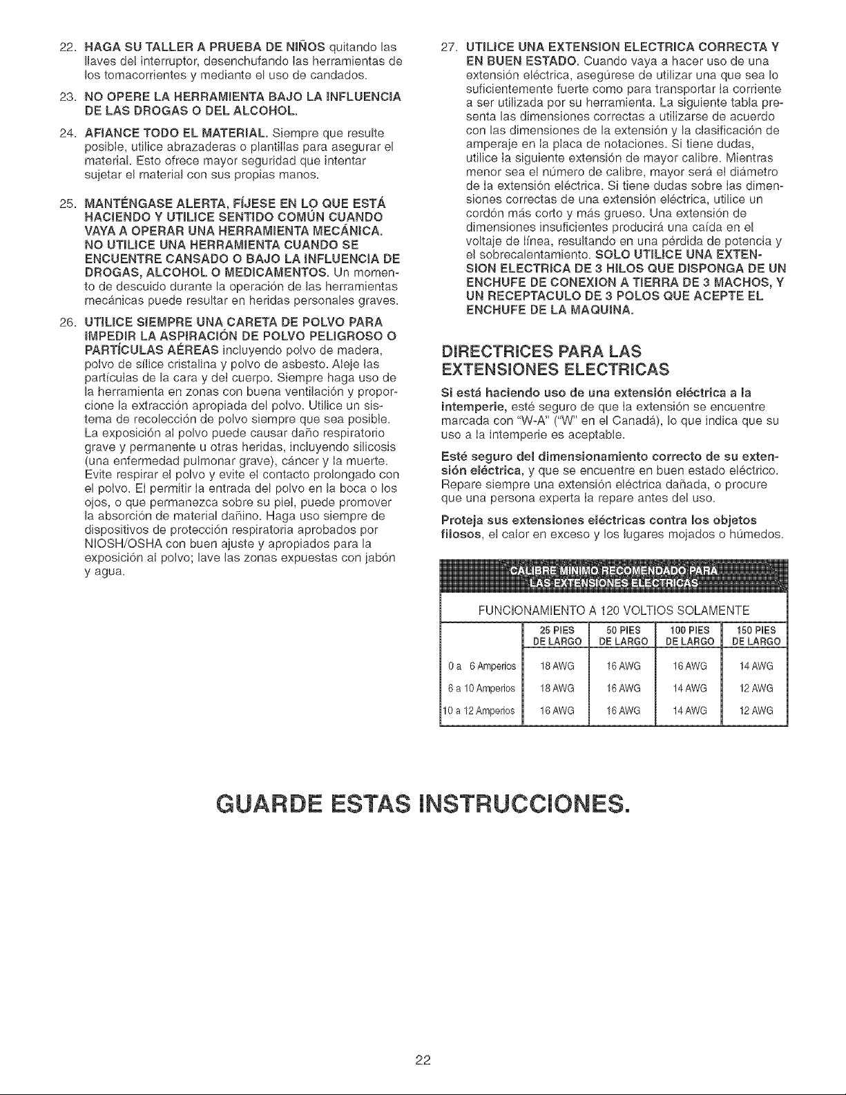
FUNCIONAMIENTO A 120 VOLTIOS SOLAMENTE
25 PIES 50 PiES t00 PIES 150 PiES
DE LARGO DE LARGO DE LARGO DE LARGO
0a 6 Amperios 18AWG 16AWG 16AWG 14AWG
6 a 10Amperios 18AWG 16AWG 14AWG 12AWG
10 a 12 Amperios 16AWG 16AWG 14AWG 12AWG
GUARDE ESTAS INSTRUCCIONES,
22
ESTA HERRAM_ENTA DEBE ESTAR CONECTADA A
TJERRA MIENTRAS QUE SE ENCUENTRE EN USO PARA
PROTEGER AL OPERARJO CONTRA LOS CHOQUES
ELC:CTRJCOS.
EN EL CASO DE UN MALFUNCJONAMtENTO O AVERJA, la
conexJdn a tierra ofrece ei trecho de menor resistencia para ia
corriente electrica y reduce el riesgo de los choques electri-
cos. Esta herramienta viene equipada con un corddn electrico
que dispone de un conductor de conexidn a tierra para ei
equipo as{ como un enchufe de conexidn a tierra. El enchufe
DEBE estar enchufado a un tomacorrJentes adaptado que
hay sido correctamente instaJado y conectado a tJerra de
acuerdo con TODOS los cddigos y ordenanzas municipales.
NO MOD_FJQUE EL ENCHUFE SUMJNJSTRADO. Haga que
un electricista calificado instale el tomacorrientes apropiado si
el enchufe no cabe en el tomacorrientes.
LA CONEXJON ELECTR_CA JNDEBIDA del conductor de
conexidn a tierra para el equipo puede resultar en el rJesgo
de choques electricos. El conductor con el aisIamiento verde
(con o sin rayas amarillas) es el conductor de conexidn a
tierra para el equipo. NO conecte el conductor de conexidn a
tierra para eI equipo a una terminacidn viva si resulta nece-
sario reparar o reempIazar el corddn eldctrico o el enchufe.
CONSULTE con un ebctricista calificado o personal de
servicio si no entiende Ias instrucciones de conexidn a tierra
comptetamente, o si no esta seguro que la herramienta estA
debidamente conectada a tierra.
SOLO UT_UCE UNA EXTENSION ELECTRJCA DE 3 NJLOS
QUE DJSPONGA DE UN ENCNUFE DE CONEX_ON A
TJERRA DE 3 MACHOS, Y UN RECEPTACULO DE 3
POLOS QUE ACEPTE EL ENCHUFE DE LA MAQUJNA.
REPONGA CUALQU_ER CORDON DANADO O GASTADO
tNMEDIATAMENTE.
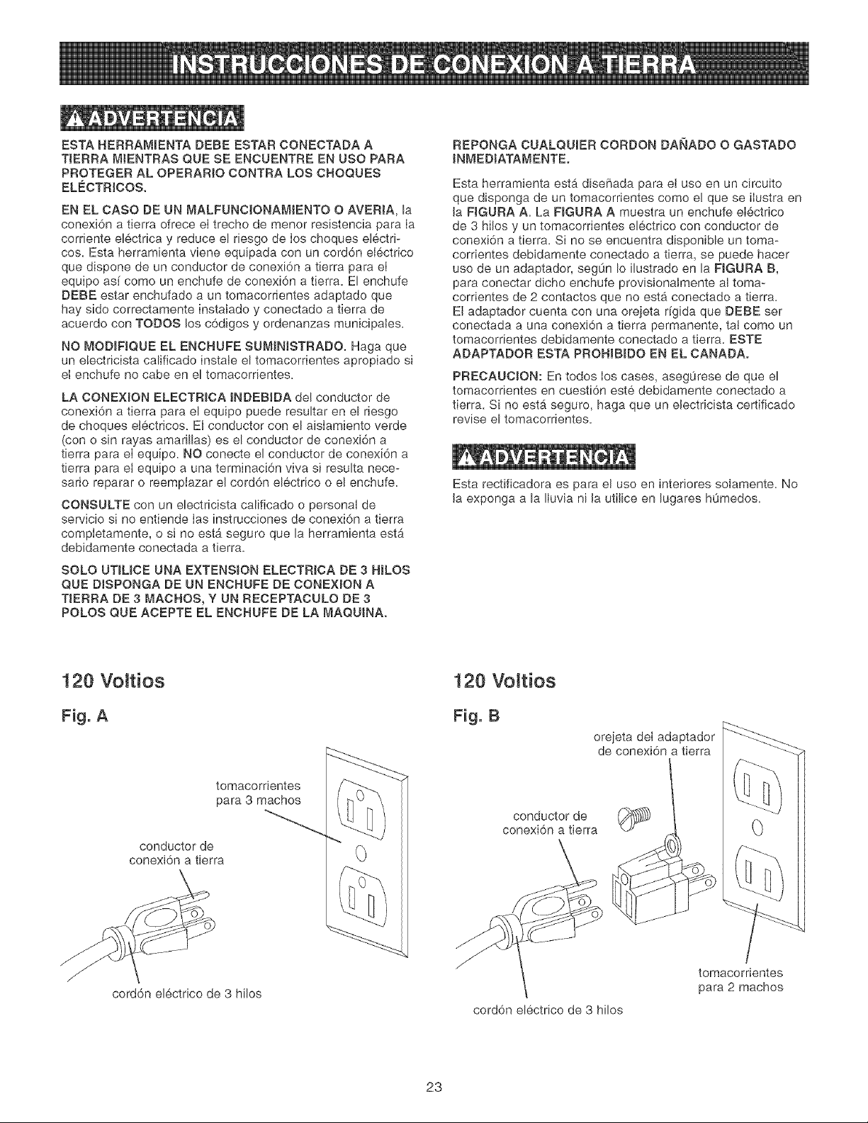
Esta herramienta esta dise[iada para et uso en un circuito
que disponga de un tomacorrientes como e! que se iIustra en
Ja FJGURA A. La F_GURA A muestra un enchufe electrico
de 3 hilos y un tomacorrientes eldctrico con conductor de
conexidn a tierra. Si no se encuentra disponible un toma-
corrientes debidamente conectado a tierra, se puede hacer
uso de un adaptador, segOn Io ilustrado en la FJGURA B,
para conectar dicho enchufe provisionaImente al toma-
corrientes de 2 contactos que no est#t conectado a tierra.
El adaptador cuenta con una orejeta rigida que DEBE ser
conectada a una conexidn a tierra permanente, taJ como un
tomacorrientes debidamente conectado a tierra. ESTE
ADAPTADOR ESTA PROHIB_DO EN EL CANADA.
PRECAUCJON: En todos los cases, aseg0rese de que el
tomacorrientes en cuestidn este debidamente conectado a
tierra. Si no est_ seguro, haga que un eJectricista certificado
revise el tomacorrientes.
Esta rectificadora es para el uso en interiores solamente. No
Ja exponga a la Iluvia ni Jautilice en lugares h0medos.
120 VoJtios
Fig. A
tomacorrientes
para 8 machos
conductor de
conexidn a tierra
corddn eldctrico de 3 hilos
120 VoJtios
Fig. B
orejeta del adaptador
de conexidn a tierra
conductor de
conexidn a tierra
corddn eldctrico de 3 hilos
tomacorrientes
para 2 machos
23
INSTRUCCmONES ESPEC{FICAS
DE SEGURIDAD
El uso de cuaiquier taladradora puede expulsar escombros
hacia Ios ojos durante Ias operaciones, Io que puede causar
dahe ocutar grave y permanente. UTJLICE PROTECC_0N
OCULAR SJEMPRE. El use de cualquier herramienta
mecanica puede expulsar escombros durante Ias opera-
ciones, Io que puede causar dare ocular grave y permanente.
Los anteojos cotidianos NO son gafas de seguridad. Utilice
Gafas de Seguridad (que cumplan con la normativa Z87.1 de
ANSi) SlEMPRE cuando vaya a operar herramientas mecani-
cas. Las gafas de seguridad estan disponibles en las tiendas
de Ventas al Detal de Sears.
Deben seguirse ciertas precauciones basicas durrante eI uso
de su taladradora. Para reducir eI riesgo de heridas, cheques
electricos o incendios, cumpla con las reglas de seguridad
que aparecen a continuaci6n:
1_ UTJLICE SIEMPRE LOS PROTECTORES OCULARES Y
DE RUEDA suministrados con la rectificadora.
2. REPONGA INMEDIATAMENTE CUALQUIER RUEDA
DE RECTIFJCACION AGRIETADA O DANADA. Una
rueda de rectificaci6n daRada puede descargar escom-
bros a atta velocidad en la direcci6n del operario. Mane]e
las ruedas de rectificaci6n con cuidado, ya que son
abrasantes_ Antes de reemplazar Ia rueda de rectifica-
ci6n, revise per si existen grietas. NO QUITE el secante
o Ia etiqueta en ambos lades de Ia rueda de rectificaci6n.
Apriete Ia tuerca deI eje justo Io suficiente come para
sujetar la rueda de rectificaci6n firmemente a la
Rectificadora de Banco. No apriete Ia tuerca excesiva-
mente. La fuerza abrazadora excesive puede daf_ar Ia
rueda de rectificaci6n. S61o utilice tas pestaf_as de rueda
proporcionadas con Ia rectificadora. Cuando vaya a
sebccionar una rueda de rectificaci6n de repuesto,
compruebe que la rueda de rectificaci6n tiene una
notaci6n de R.RM. mas alta que las R.RM. mb,ximas de
la Rectificadora de Banco.
3. EL D_AMETRO DE LAS RUEDAS DE RECT_FJCACION
SE REDUCIRA CON EL USO. Ajuste los portaherramien-
tas y los protectores de chispas para conservar una dis-
tancia de 1/16" de la rueda.
4. NO SE INCORPORE EN FRENTE DE LA RECTIF_CA-
DORA DE BANCO CUANDO VAYA A ENCENDERLA.
Incorp6rese a un Iado de Ia Rectificadora de Banco y
enciendaia. Espere al lado por un minuto hasta que la
5.
rectificadora alcance plena velocidad. Siempre existe Ia
posibilidad de que Ios escombros de una rueda de rectifi-
caci6n dahada puedan descargarse hacia el operario.
LA RECTIFICADORA DE BANCO PRODUCJRA
CHISPAS Y ESCOMBROS DURANTE LAS OPERA-
CJONES DE RECT_FJCACION Asegurese que no
existan materiabs infiamables en Ias cercanfas. Limpie
e! polvo residual de la rectificaci6n de la parte posterior
de la Rectificadora de Banco.
6. JAMAS FUERCE EL MATERIAL CONTRA LA RUEDA
DE RECTJFICACION, especialmente si Ia rueda se
encuentra fr[a. Aplique eI material lentamente, permitien-
do que la rueda de rectificaci6n tenga la oportunidad de
calentarse. Esto reducira la posibilidad de ruptura de la
rueda. NO rectifique utilizando Ios lades de las ruedas de
rectificaci6n. NO aptique refrigerante directamente sobre
la rueda de rectificaci6n.
7. MANTENGA TODAS LOS PROTECTORES DE RUEDA
EN SU SITIO. NO UTJLICE LA RECTJFICADORA DE
BANCO CON LOS PROTECTORES DE RUEDA FUERA
DE LUGAR,
8_ MANTENGA LOS PORTAHERRAMIENTAS F_RME-
MENTE APRETADOS.
9_ UTlUCE SIEMPRE EL ACABADOR DE RUEDA
SUM_NISTRADO PARA ACABAR LA CARA DE LA
RUEDA DE RECT_NCACION.
10n
Hay INFORMACION ADICIONAL acerca de la operaci6n
segura y correcta de este producto disponible de:
@ Power Tool institute
(Insituto de Herramientas Mecb.nicas)
1300 Summer Avenue, Cleveland OH 44115-2851
www.powertoolinstitute.org
@ National Safety Council
1121 Spring Lake Drive, Itasca, IL 60143-3201
@ American National Standards institute
25 West 43rd Street, 4th Floor, New York, NY 10036
www.ansLorg
@
ANSi 0.01, Requisitos de Seguridad para Maquinas
de Ebanister[a, y Ios reglamentos del U.S.
Department of Labor
www.osha.g_V_
11_ GUARDE ESTAS tNSTRUCC_ONES. Refierase a elias
con frecuencia y utilfcelas para instruir a los demb,s_
GUARDE ESTAS INSTRUCCIONES.
ACCESORUOS DUSPONIBLES
Visite su Departamento de Ferreterfa de Sears o consutte el
Catalogo de Herramientas Mecanicas y de Mane para los
siguientes accesorios:
ARTICULO
Ruedas de rectificaci6n de
repuesto
Ruedas de alambre y pulido
Espaciadores
Acabadores de rueda
Estante universal
NUMERO DE EXISTENCIA
Ver catalogo o tienda
Ver catalogo o tienda
Ver catalogo o tienda
Ver catalogo o tienda
Ver cat&logo o tienda
Sears podra recomendar otros accesorios que no aparecen
listados en ese manual.
Consulte con su Departamento de Ferreter[a de Sears o con-
suite eI CatbJogo de Herramientas Mecanicas y de Mane para
otros accesorios:
No utilice ning0n accesorio a menos que haya le[do el
manual del Propietario para dicho accesorio.
S61o utilice los accesorios recomendados para esta
Rectificadora de Banco. El uso de otros accesorios podra
ocasionar lesionamientos graves y daRar la Rectificadora de
Banco.
24
Fig. C G H
E
C ...................................m
N
\
j K
L
U
S
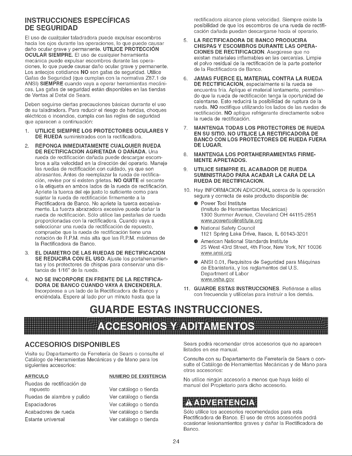
DESEMPAQUE Y VERIFICACION DE
CONTENIDOS (Fig. C)
Esta rectificadora de banco exigirb_ una cantidad mfnima de
ensamblaje. Se suminJstra una Ilave de extremo abierto de
12 mm x 10 mm para montar los EnsambIados de Portaherra-
mientas y los Ensamblados de Protector de Chispas.
1.
2.
Retire las piezas de todas las cajas y col6quelas sobre
una superficie de trabajo limpia.
Retire cualquier material protectivo y revestimiento de
todas las piezas y de Ia rectificadora de banco. Los
revestimientos protectivos pueden quitarse mediante et
rociado de WD-40 en las piezas y limpi_ndolas con un
paso suave. Tal vez sea necesario reaIizar esta
operaci6n varias veces antes de poder quitar todos los
revestimientos protectivos completamente.
PRECAUCION: NO utilice acetona, gasolina ni diluyente
de laca para quitar ningOn revestimiento protectivo de su
rectificadora de banco.
3.
Compare los art[culos con la Figura C. Verifique que
todos los articuIos esten contabilizados antes de descar-
tar la caja de env[o. Si faltan piezas, comun[quese con la
Linea de Ayuda al Cliente, 1-800-897-7709.
Para evitar heridas graves, no intente enchufar el cord6n de
potencia y encienda Ia Rectificadora de Banco si falta cual-
quier pieza. La Rectificadora de Banco s61o podr4, encender-
se despues de que todas Ias piezas hayan sido correcta-
mente obtenidas e instaIadas.
Los siguientes artfculos seran proporcionados en la caja de
envio:
A. Rectificadora (no ilustrada)
B. Escudo ocular (2)
C. Tornillos de carrocer[a M6 x 80 mm (2)
D. Espaciador (2)
E. Arandela plana M6 (2)
F. Perilla deI escudo ocular (2)
G. Acabador de la rueda
H. Tornillo de cabeza hexagonal 5/16-18 x 1/2 pulg. (4)
I. Arandela plana 5/16 pulg. (4)
J. Supresor de chispas, izquierdo
K. Supresor de chispas, derecho
h Arandela plana 1/4 pulg. (2)
M. Tornillo de cabeza hexagonal 1/4-20 x 1/4 pulg. (2)
N. Apoyo del portaherramientas, izquierdo
O. Apoyo del portaherramientas, derecho
R Portaherramientas derecho
Q. Placa de afilado de la broca
R. Perilla deI portaherramientas (2)
S. randela plana 5/16 pulg. (2)
11 Portaherramientas izquierdo
U. Llave especial
V. Bandeja de templado (no ilustrada).
25
14
15
16
4
14
12
11
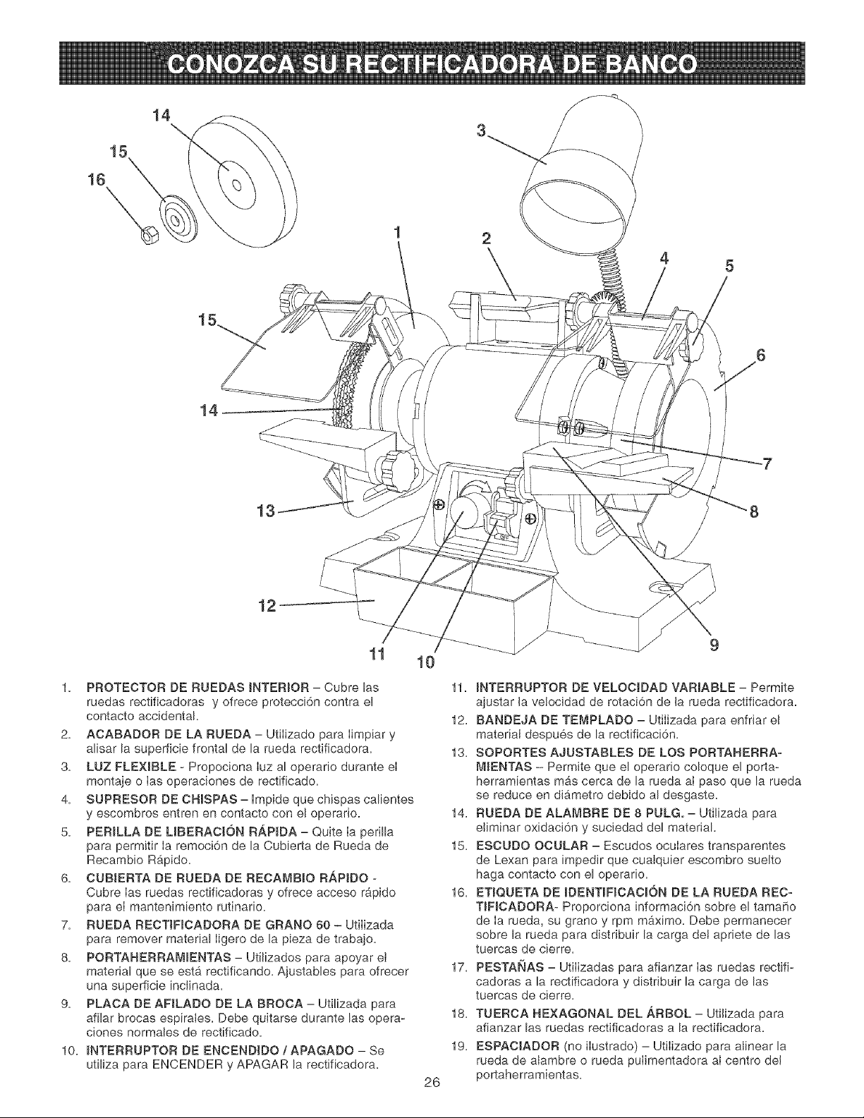
1. PROTECTOR DE RUEDAS iNTERiOR - Cubre las
ruedas rectificadoras y ofrece protecci6n contra el
contacto accidental.
2. AOABADOR DE LA RUEDA - Utilizado para Iimpiar y
alisar la superficie frontal de la rueda rectificadora.
3. LUZ FLEXIBLE - Propociona Iuz ar operario durante eI
montaje o Ias operaciones de rectificado.
4. SUPRESOR DE CHISPAS - Impide que chispas calientes
y escombros entrenen contacto con el operatic.
5. PERILLA DE UBERACION RAP_DA - Quite Ia perilla
para permitir Ia remoci6n de la Cubierta de Rueda de
Recambio Rb,pido.
6. CUB_ERTA DE RUEDA DE RECAMB_O RAPIDO -
Cubre Ias ruedas rectificadoras y ofrece acceso rapido
para eI mantenimiento rutinario.
7. RUEDA RECTINCADORA DE GRANO 60 - Utilizada
para remover material iigero de la pieza de trabajo.
8. PORTAHERRAM_ENTAS- Utilizados para apoyar ei
material que se esta rectificando. Ajustables para ofrecer
una superficie inclinada.
9. PLACA DE AFJLADO DE LA BROCA - Utilizada para
afilar brocas espirales. Debe quitarse durante las opera-
ciones normales de rectificado.
10. _NTERRUPTOR DE ENCEND_DO / APAGADO - Se
utiliza para ENCENDER y APAGAR la rectificadora.
10
26
11. INTERRUPTOR DE VELOCJDAD VARIABLE - Permite
ajustar la ve!ocidad de rotaci6n de la rueda rectificadora.
12. BANDEJA DE TEMPLADO - Utilizada para enfriar el
material despues de la rectificaci6n.
13. SOPORTES AJUSTABLES DE LOS PORTAHERRA_
MIEN'rAS - Permite que el operario coloque el porta-
herramientas mas cerca de la rueda aI paso que la rueda
se reduce en dib,metro debido al desgaste.
14. RUEDA DE ALAt_BRE DE 8 PULG, - Utilizada para
eliminar oxidaci6n y suciedad del material.
15. ESCUDO OCULAR - Escudos ocuIares transparentes
de Lexan para impedir que cualquier escombro suelto
haga contacto con el operario.
16. ET_QUETA DE _DENT_FICACK_N DE LA RUEDA REC-
T_F_CADORA- Proporciona informaci6n sobre el tamaSo
de Ia rueda, su grano y rpm maximo. Debe permanecer
sobre la rueda para distribuir la carga de! apriete de las
tuercas de cierre.
17. PESTANAS - Utilizadas para afianzar Ias ruedas rectifi-
cadoras a la rectificadora y distribuir la carga de las
tuercas de cierre.
l& TUERCA HEXAGONAL DEL ARBOL - Utilizada para
afianzar las ruedas rectificadoras a la rectificadora.
19. ESPACIADOR (no ilustrado) - Utilizado para alinear la
rueda de alambre o rueda pulimentadora aI centro del
portaherramientas.
LaRectificadoradeBancoseproporcionacon
PortaherramientasJzquierdoy derechodedospiezas.Ambos
PortaherramJentasdisponendeunasuperficiepianay suave
contraIacuaJpuedecolocarsumaterial,Seincluyeuna
PIacadeAfiIadodeBrocas,Estapiacasecolocasobreel
portaherramientasderechosoJamenteyseusaparaafilar
brocasespirales,
Fig. E
/
E
2,
NO ensambIe Ia RectJficadora de Rueda hasta que este
seguro que Ja herramienta NO ESTE enchufada,
NO ensambIe Ia Rectificadora de Banco hasta que este
seguro que el interruptor de energ[a este en la pocisi6n
de APAGADO,
3, NO ensambJe Ia Rectificadora de Banco hasta que este
seguro de que las ruedas rectificadoras esten firmemente
apretadas a Ja Rectificadora de Banco,
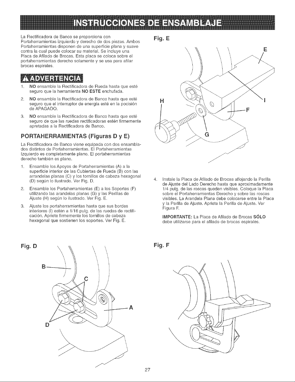
PORTAHERRAMIENTAS (Figuras O y E)
La Rectificadora de Banco vJene equipada con dos ensambla-
dos distintos de Portaherramientas. El Portaherramientas
Izquierdo es compietamente piano, El portaherramientas
derecho tambien es piano,
Ensambie los Apoyos de Portaherramientas (A) a la
superficie interior de las Cubiertas de Rueda (B) con Ias
arrandelas planas (C) y los tornillos de cabeza hexagonal
(D) seg0n Io ilustrado, Ver Fig, D,
2, EnsambJe los Portaherramientas (E) a los Soportes (F)
utilizando Ias arandelas planas (G) y las Perillas de
Ajuste (H) seg0n Io ilustrado, Vet Fig. E.
3,
Ajuste los portaherramientas hasta que sus bordes
interiores (I) esten a 1/16 puig, de las ruedas de rectifi-
caci6n, Apriete firmemente los tornilIos de cabeza
hexagonal que sostienen los soportes, Vet Fig, E,
H
4,
G
Instale Ia Placa de Afilado de Brocas afiojando la PerilIa
de Ajuste deI Lado Derecho hasta que aproximadamente
1/4 pulg, de Jas roscas queden visibJes, Coloque la Piaca
sobre el Portaherramientas Derecho y sobre las roscas
visibles. La Arandeta Plana debe colocarse entre la Placa
y la PeriJla de Ajuste, Apriete Ja Perilla de Ajuste, Ver
Figura R
tMPORTANTE: La Placa de Afilado de Brocas SOLO
debe utiiizarse para el afiJado de brocas espirales,
Fig. D
Fig. F
C
D
27
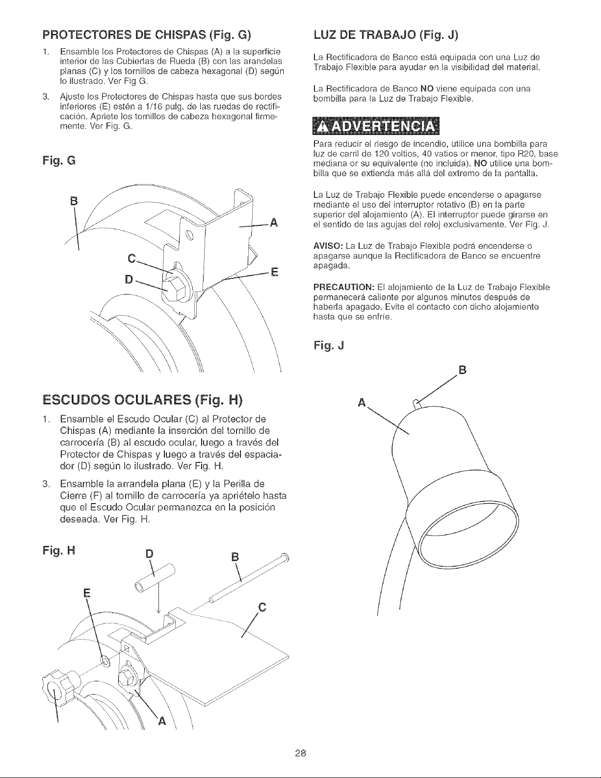
PROTECTORES DE CHISPAS (Fig. G)
Ensamble los Protectores de Chispas (A) a la superficie
interior de las Cubier[as de Rueda (B) con las arandelas
planas (C) y los tornil!os de cabeza hexagonal (D) segOn
Io ilustrado. Ver Fig G.
3.
Ajuste los Protectores de Chispas hasta que sus bordes
[nferiores (E) esten a 1/16 pulg. de las ruedas de rectifi-
caci6n. Apriete los tornillos de cabeza hexagonal firme-
mente. Ver Fig. G.
Fig. G
LUZ DE TRABAJO (Fig. J)
La Rectificadora de Banco esta equipada con una Luz de
Traba]o Flexible para ayudar en la visibilidad del material.
La Rectificadora de Banco NO viene equipada con una
bombilla para la Luz de Trabajo Flexible.
Para reducir el riesgo de [ncend[o, utilice una bombilla para
luz de carril de 120 voltios, 40 vatios or menor, tipo R20, base
mediana or su equivalente (no [ncluida). NO utilice una bom-
billa que se extienda mas alia del extremo de Ia pantalla.
La Luz de Trabaio Flexible puede encenderse o apagarse
mediante el use deI interrupter rotativo (B) en Ia parte
superior del aloiamiento (A). El interrupter puede girarse en
el sentido de las aguias del reloj exclusivamente. Ver Fig. J.
AVISO: La Luz de Trabaio Flexible podrb, encenderse o
apagarse aunque la Rectificadora de Banco se encuentre
apagada.
PRECAUTION: El alojamiento de ia Luz de Trabajo Flexible
permanecera caliente por aigunos minutos despues de
haberia apagado. Evite el contacto con dicho aloiamiento
hasta que se enfrie.
Fig. J
B
ESCUDOS OCULARES (Fig. H)
1, Ensamble el Escudo Ocular (C) al Protector de
Chispas (A) mediante la inserci6n del tornillo de
carroceria (B) al escudo ocular, luego a traves del
Protector de Chispas y luego a traves del espaciao
dor (D) segun Io ilustrado, Ver Fig, H,
3, Ensamble la arrandela plana (E) y la Perilla de
Cierre (F) al tornillo de carroceria ya aprietelo hasta
que el Escudo Ocular permanezca en la posici6n
deseada, Ver Fig, H,
A
28
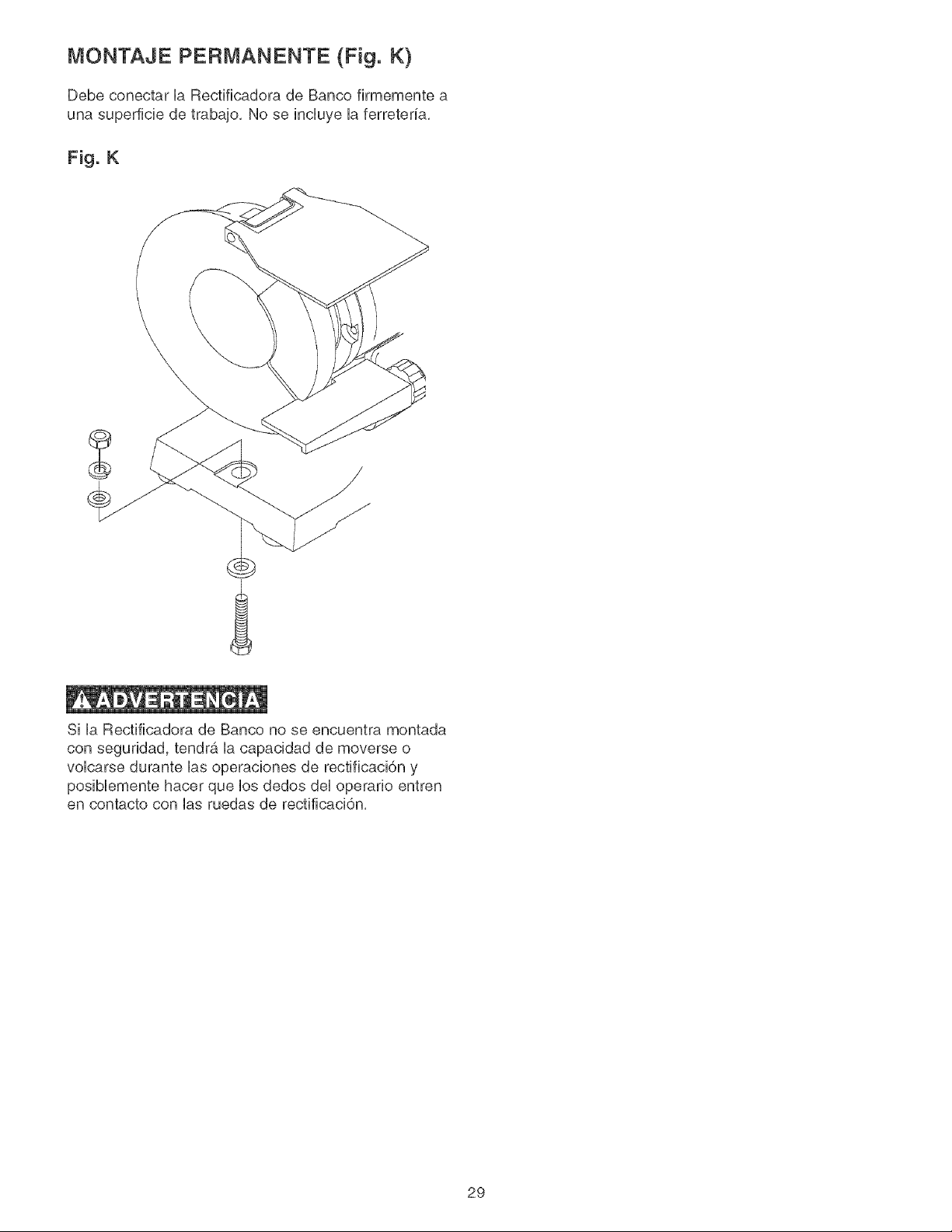
MONTAJE PERMANENTE (Fig. K)
Debe conectar UaRectificadora de Banco firmemente a
una superficie de trabajo, No se incUuye Uaferreteria,
Fig. K
Si UaRectificadora de Banco no se encuentra montada
con segundad, tendr¢4 Uacapacidad de moverse o
voUcarse durante Uasoperaciones de rectificacidn y
posiMemente hacer que Uosdedos deUoperano entren
en contacto con Uasruedas de rectificaci6n,
29
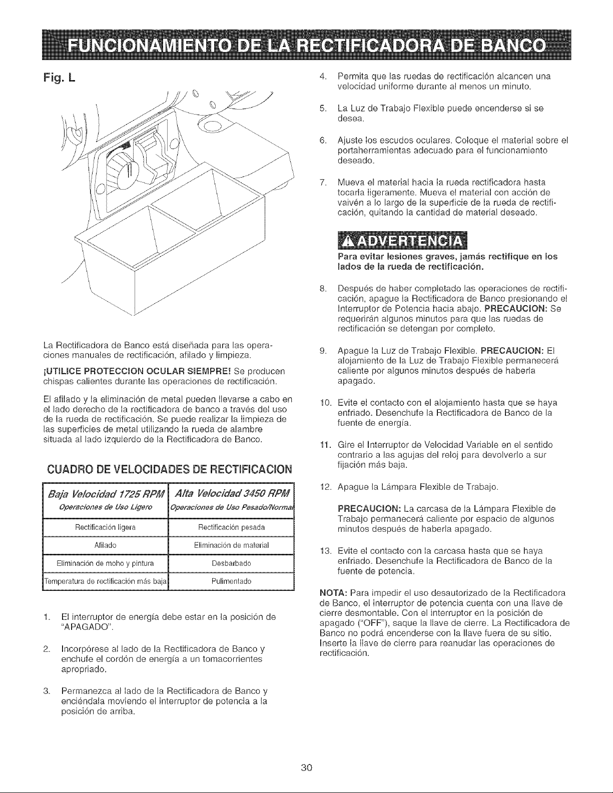
Fig. L 4, Permita que bs ruedas de rectificaci6n alcancen una
velocidad uniforme durante aI menos un minute.
La Rectificadora de Banco estb_disehada para las opera-
ciones manuaIes de rectificaci6n, afilado y Iimpieza.
iUTtLICE PROTECCJON OCULAR SlEMPRE! Se producen
chispas calientes durante las operaciones de rectificaci6n.
El afilado y Ia etiminaci6n de metal pueden Ibvarse a cabo en
et lade derecho de Ia rectificadora de banco a traves deI uso
de Ia rueda de rectificaci6n. Se puede realizar la Iimpieza de
Jas superficies de metal utilizando Ia rueda de alambre
situada al Jado izquierdo de la Rectificadora de Banco.
CUADRO DE VELOCIDADES DE RECTIFICACION
Baja Ye/ocidad 1725 RPM A/ta Ve/ocidad 3450 RPM
Operacionesde Uso/Jgero Operacionesde UsoPesado/Normm
Rectificacionligera Rectificaci6npesada
Afilado Eliminaci6nde material
Eliminaci6nde mohoy pintura Desbarbado
Temperaturade [ectificaci6nrnasbaja Pulimentado
2.
3.
El interruptor de energfa debe estar en Ja posici6n de
"APAGADO'.
Incorp6rese al lade de la Rectificadora de Banco y
enchufe el cord6n de energfa a un tomacorrientes
apropriado.
Permanezca al Iado de la Rectificadora de Banco y
enciendala moviendo el interruptor de potencia a Ja
posici6n de arriba.
5.
6.
7.
La Luz de Trabajo Flexible puede encenderse si se
desea.
Ajuste Ios escudos oculares. Coloque el material sobre el
portaherramientas adecuado para el funcionamiento
deseado.
Mueva el material hacia Ia rueda rectificadora hasta
tocarla Iigeramente. Mueva ei material con acci6n de
vaiven a Io largo de la superficie de Ia rueda de rectifi-
caci6n, quitando la cantidad de material deseado.
Para evitar lesiones graves, jamas rectifique en los
mados de la raeda de rectificaciono
8.
Despu6s de haber compbtado las operaciones de rectifi-
caci6n, apague Ia Rectificadora de Banco presionando et
Interrupter de Potencia hacJa abajo. PRECAUOJON: Se
requeriran aJgunos minutes para que las ruedas de
rectificaci6n se detengan per complete.
9.
Apague Ia Luz de Trabajo Flexibie. PRECAUCION: El
alojamiento de la Luz de Trabajo Flexible permanecera
caliente por algunos minutes despues de habeda
apagado.
10. Evite el contacto con el alojamiento hasta que se haya
enfriado. Desenchufe Ja Rectificadora de Banco de la
fuente de energia.
11. Gire e! Interrupter de Velocidad Variable en el sentido
contrario alas agujas del reloj para devolveflo a sur
fijaci6n mas baja.
12, Apague Ja Lampara Flexible de Trabajo,
PRECAUC_ON: La carcasa de Ia Lampara Flexible de
Trabajo permanecera caliente por espacio de algunos
minutes despues de habeda apagado.
13. Evite el contacto con Ia carcasa hasta que se haya
enfriado. Desenchufe Ja Rectificadora de Banco de la
fuente de potencia.
NOTA: Para impedir el uso desautorizado de Ia Rectificadora
de Banco, e! interrupter de potencia cuenta con una IIave de
cierre desmontabb. Con el interruptor en la posici6n de
apagado ("OFF"), saque la Ilave de cierre. La Rectificadora de
Banco no podr#, encenderse con Ia Ilave fuera de su sitio.
Inserte Ia IIave de cierre para reanudar las operaciones de
rectificaci6n.
3O
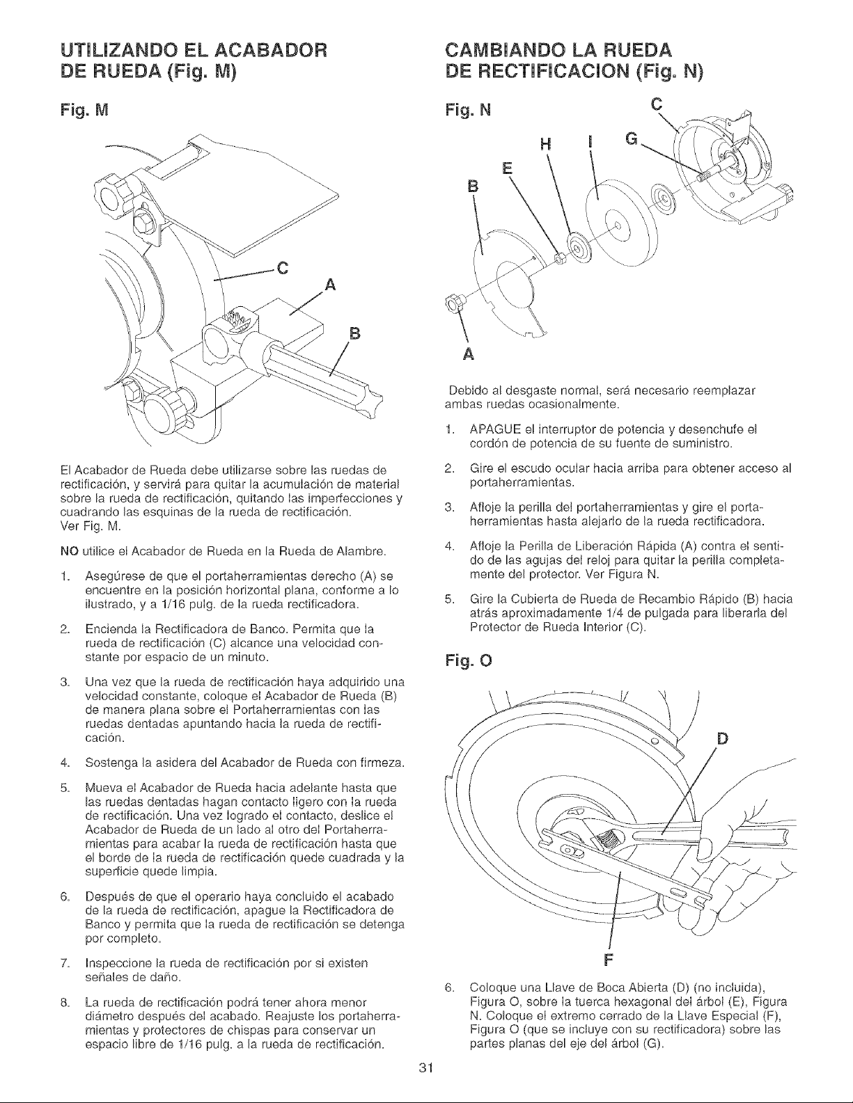
UTJUZANDO EL ACABADOR
DE RUEDA (Fig. M)
Fig. M
A
B
El Acabador de Rueda debe utJlizarse sobre las ruedas de
rectificaci6n, y servira para quitar la acumuIaci6n de material
sobre la rueda de rectificaci6n, quitando Ias imperfecciones y
cuadrando Jas esquinas de la rueda de rectificaci6n.
Ver Fig. M.
NO utilice el Acabador de Rueda en la Rueda de Alambre.
1. Asegurese de que el portaherramientas derecho (A) se
encuentre en Ja posici6n horizontal plana, conforme a Io
ilustrado, y a 1/16 puIg. de Ia rueda rectificadora.
2. Encienda Ja Rectificadora de Banco. Permita que Ia
rueda de rectJficaci6n (C) alcance una velocidad con-
stante per espacio de un minute.
3.
Una vez que la rueda de rectificaci6n haya adquindo una
velocidad constante, coloque el Acabador de Rueda (B)
de manera plana sobre el Portaherramientas con Ias
ruedas dentadas apuntando hacia Ja rueda de rectifi-
caci6n.
4. Sostenga Ja asJdera del Acabador de Rueda con firmeza.
5.
Mueva el Acabador de Rueda hacia adelante hasta que
las ruedas dentadas hagan contacto Iigero con Ia rueda
de rectificaci6n. Una vez Iogrado el contacto, deslice e!
Acabador de Rueda de un lade aI otro deI Portaherra-
mientas para acabar la rueda de rectificaci6n hasta que
el borde de Ia rueda de rectificaci6n quede cuadrada y la
supefficie quede Jimpia.
6.
Despues de que el operario haya concluido el acabado
de la rueda de rectificaci6n, apague la Rectificadora de
Banco y permita que Ia rueda de rectificaci6n se detenga
per complete.
7. Inspeccione la rueda de rectificaci6n por si existen
seRales de dare.
8.
La rueda de rectificaci6n podr& tener ahora menor
di&metro despues deI acabado. Reajuste los portaherra-
mientas y protectores de chispas para conservar un
espacio libre de 1/16 pulg. a Ja rueda de rectificaci6n.
31
CAMBJANDO LA RUEDA
DE RECTJNCACJON (Fig. N)
Fig. N
H
E
B
A
Debido al desgaste normal, ser& necesario reempJazar
ambas ruedas ocasionalmente.
1.
2.
3.
4.
APAGUE e! interruptor de potencia y desenchufe el
cord6n de potencia de su fuente de suministro.
Gire el escudo ocular hacia arnba para obtener acceso al
portaherramientas.
Afioje la perilla del portaherramientas y gire eJ porta-
herramientas hasta alejarIo de Ja rueda rectificadora.
Afioje la PeriJla de Liberaci6n Rb,pida (A) contra el senti-
do de las agujas deI reloj para quitar Ja perilla compJeta-
mente del protector. Ver Figura N.
Gire la Cubierta de Rueda de Recambio Rapido (B) hacia
atr_.s aproximadamente 1/4 de pulgada para liberada deJ
Protector de Rueda interior (C).
Fig. O
6.
Co!oque una Llave de Boca Abierta (D) (no incIuida),
Figura O, sobre Ia tuerca hexagonal deI arbol (E), Figura
N. Coloque el extreme cerrado de la Llave Especial (F),
Figura O (que se incluye con su rectificadora) sobre las
partes planas del eje del &rbol (G).
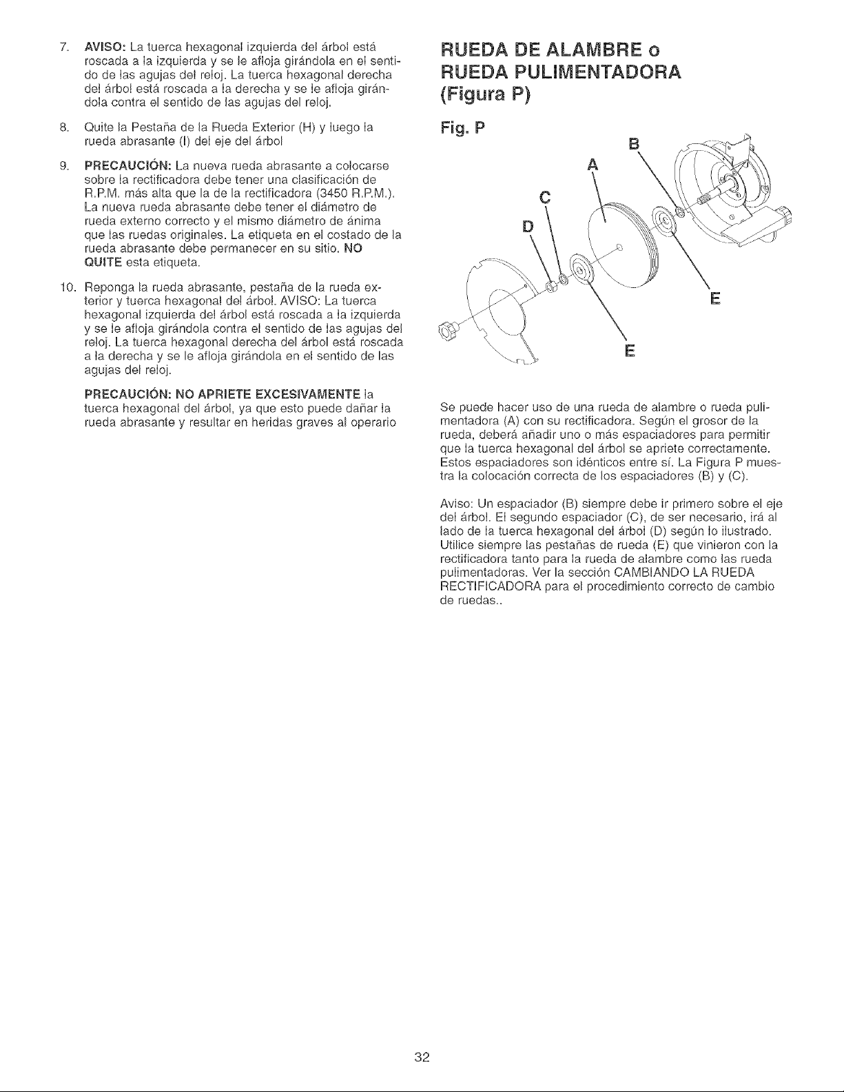
7.
AVlSO: La tuerca hexagonal izquierda del _rbot esta
roscada a Ia izquierda y se le afioja girandola en eI senti-
do de Ias agujas dei reloj. La tuerca hexagonal derecha
deI arboI esta roscada a Ia derecha y se Ie afioja giran-
doia contra el sentido de las agujas del reloi.
8.
9.
Quite la Pestafla de la Rueda Exterior (H) y Iuego Ia
rueda abrasante (I) deI eje del arbol
PRECAUCI6N: La nueva rueda abrasante a colocarse
sobre Ia rectificadora debe tener una clasificaci6n de
R.P.M. mas alta que la de la rectificadora (3450 R.RM.).
La nueva rueda abrasante debe tener e! diametro de
rueda extemo correcto y el mismo di#,metro de anima
que Ias ruedas originales. La etiqueta en el costado de la
rueda abrasante debe permanecer en su sitio. NO
QUITE esta etiqueta.
10. Reponga la rueda abrasante, pesta_a de la rueda ex-
terior y tuerca hexagonal dei arboi. AVISO: La tuerca
hexagonal izquierda del arbol esta roscada a Ia izquierda
y se Ie afioia gir_ndola contra eI sentido de Ias agujas de!
re!oi. La tuerca hexagonal derecha del arbol esta roscada
a ia derecha y se le afioia girandola en el sentido de las
aguias del reloj.
PRECAUCION: NO APRIETE EXCESIVAMENTE Ia
tuerca hexagonal del arboI, ya que esto puede da5ar Ia
rueda abrasante y resultar en heridas graves al operafio
RUEDA DE ALAMBRE o
RUED.& PUUMENTADORA
(Figura P)
Fig, P
B
A
C
D
E
E
Se puede hacer uso de una rueda de alambre o rueda puli-
mentadora (A) con su rectificadora. Seg0n el grosor de la
rueda, deber_, afladir uno o m#,s espaciadores para permitir
que Ia tuerca hexagonal del arbol se apriete correctamente.
Estos espaciadores son identicos entre si. La Figura P mues-
tra la colocaci6n correcta de los espaciadores (B) y (C).
Aviso: Un espaciador (B) siempre debe ir primero sobre el eie
deI arboi. EI segundo espaciador (C), de ser necesario, ira al
lade de Ia tuerca hexagonal deI arboI (D) segun Io ilustrado.
Utilice siempre las pesta[ias de rueda (E) que vinieron con ta
rectificadora tanto para Ia rueda de alambre come las rueda
pulimentadoras. Ver la secci6n CAMBIANDO LA RUEDA
RECTIFICADORA para el procedimiento correcto de cambio
de ruedas..
32
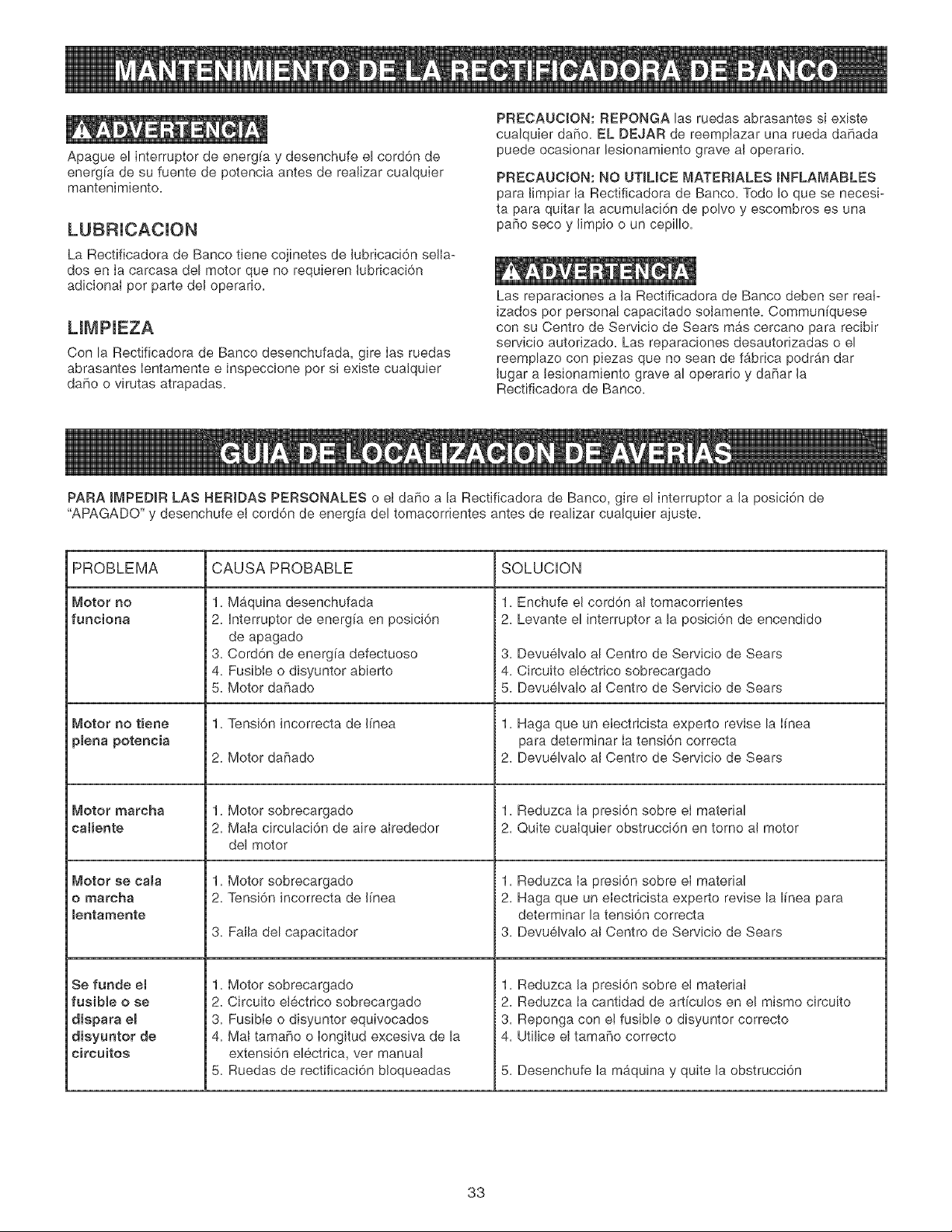
Apague el interruptor de energ[a y desenchufe el cord6n de
energ[a de su fuente de potencia antes de realizar cualquier
mantenimiento.
LUBRICACION
La Rectificadora de Banco tiene cojinetes de lubricaci6n sella-
dos en Ia carcasa del motor que no requieren lubricaci6n
adicionaI por parte del operario.
LIMPIEZA
Con la Rectificadora de Banco desenchufada, gire Ias ruedas
abrasantes Ientamente e inspeccione por si existe cualquier
daho o virutas atrapadas.
PRECAUCION: REPONGA las ruedas abrasantes si existe
cualquier dafio. EL DEJAR de reemptazar una rueda dahada
puede ocasionar lesionamiento grave al operario.
PRECAUCION: NO UTILICE MATERIALES INFLAMABLES
para Iimpiar Ia Rectificadora de Banco. Todo Io que se necesi-
ta para quitar la acumutaci6n de polvo y escombros es una
pa5o seco y limpio o un cep[llo.
Las reparaciones a la Rectificadora de Banco deben ser reai-
izados por personal capacitado solamente. Commun[quese
con su Centro de Servicio de Sears mas cercano para recibir
servicio autorizado. Las reparaciones desautorizadas o el
reemplazo con piezas que no sean de fgbrica podran dar
lugar a lesionamiento grave al operar[o y daBar la
Rectificadora de Banco.
PARA IMPEDIR LAS HERIDAS PERSONALES o el da5o a la Rectificadora de Banco, gire el interruptor a la posici6n de
"APAGADO" y desenchufe el cord6n de energ[a del tomacorrientes antes de realizar cualquier ajuste.
PROBLEMA
Motor no
funciona
Motor no tiene
plena potencia
Motor marcha
caliente
Motor se cala
o marcha
lentamente
Se fande et
fusible o se
dispara el
disyuntor de
circuitos
CAUSA PROBABLE SOLUCION
1. Maquina desenchufada
2. Interruptor de energia en posicion
de apagado
3. Cord6n de energia defectuoso
4. Fusible o disyuntor abierto
5. Motor dahado
1. Tensi6n incorrecta de I[nea
Motor dahado
1. Motor sobrecargado
2. Mala clrculacl6n de alre alrededor
del motor
1. Motor sobrecargado
2. Tensi6n incorrecta de I[nea
3. Falla del capacitador
1. Motor sobrecargado
2. Circulto electrico sobrecargado
3. Fusible o disyuntor equivocados
4. Mat tama_o o Iongltud exceslva de la
extensi6n electrica, ver manual
5. Ruedas de rectificaci6n bloqueadas
1. Enchufe el cord6n al tomacorrientes
2. Levante el interruptor a la posici6n de encendido
3. Devuelvalo al Centro de Servic[o de Sears
4. Circuito etectrico sobrecargado
5. Devuelvalo al Centro de Servicio de Sears
1. Haga queun eIectricista experto revise la I[nea
para determinar Ia tensi6n correcta
2. Devuelvalo al Centro de Servicio de Sears
1. Reduzca Ia presi6n sobre el material
2. Quite cualquier obstrucci6n en torno al motor
1. Reduzca Ia presi6n sobre el material
2. Haga queun electricista experto revise la I[nea para
determinar la tensi6n correcta
3. Devuelvalo al Centro de Servicio de Sears
1. Reduzca la presi6n sobre el material
2. Reduzca ia cantidad de articutos en el mismo circuito
3. Reponga con e! fusible o disyuntor correcto
4. Utilice el tamafio correcto
5. Desenchufe la maquina y quite la obstrucci6n
33

34

35

iiiiiiiiiiiiiiiiii
iiiiiiiiiiiiiiiiii
iiiiiiiiiiiiiiiiii
iiiiiiiiiiiiiiiiii
iiiiiiiiiiiiiiiiii
iiiiiiiiiiiiiiiiii
iiiiiiiiiiiiiiiiii
iiiiiiiiiiiiiiiiii
iiiiiiiiiiiiiiiiii
iiiiiiiiiiiiiiiiii
iiiiiiiiiiiiiiiiii
iiiiiiiiiiiiiiiiii
iiiiiiiiiiiiiiiiii
iiiiiiiiiiiiiiiiii
iiiiiiiiiiiiiiiiii
iiiiiiiiiiiiiiiiii
iiiiiiiiiiiiiiiiii
iiiiiiiiiiiiiiiiii
iiiiiiiiiiiiiiiiii
iiiiiiiiiiiiiiii
iiiiiiiiiiiiiiii
iiiiiiiiiiiiiiii
iiiiiiiiiiiiiiii
iiiiiiiiiiiiiiii
iiiiiiiiiiiiiiii
iiiiiiiiiiiiiii_
You r Horne
For repair-in your home-of all major brand appliances,
lawn and garden equipment, or heating and cooling systems,
no matter who made it, no matter who sold it!
For the replacement parts, accessories and
owner's manuals that you need to do-it-yourself.
For Sears professional installation of home appliances
and items like garage door openers and water heaters.
1-800-4-MY-HOME ® (1-8oo-469-4663)
Call anytime, day or night (U.S.A. and Ca nada)
w_.sears.comwww.sears.ca
OurHome
For repair of carry-in items like vacuums, lawn equipment,
and electronics, call or go on-line for the location of your nearest
Sears Parts & Repair Center.
1-800-488-1222
Call anytime, day or night (U.S.A. only)
www.sears.com
To purchase a protectionagreement (U.S.A.)
or maintenance agreement (Canada)on a product serviced by Sears:
1-800-827-6655 (U.S.A.) 1-800-361-6665 (Canada)
Pard pedir servicio de reparacicn Au Canada pour service en frangais:
a domicilio, y pard ordenar piezas: 1-800-LE-FOYER Mc
1-888-SU-HOGAR sM
TM SM
® Registered Trademark / Trademark / Service Mark of Sears, Roebuck and Co.
SM
® Marca Registrada / TM Marca de Fabrica / Marca de Servicio de Sears, Roebuck and Co.
MD
MCMarque de commerce / Marque dCposCe de Sears, Roebuck and Co. ® Sears, Roebuck and Co.
