Read all instructions before you operate your grill.
Save these instructions!
Conforms to
ANSI STD Z21.58b-2012
Certified to CSA STD 1.6b-2012
Outdoor Cooking Gas Appliance
To installer or person assembling grill:Leave this manual with grill for future reference.
To consumer: Keep this manual for future reference.
www.sunstonemetalproducts.com
3174816
USE & CARE GUIDE
SUNSTONE® SERIES
GRILL
GAS GRILLS

Welcome & Congratulations
Congratulations on your purchase of a new Sunstone grill! We are very proud of our product and we are
completely committed to providing you with the best service possible. Your satisfaction is our #1 priority.
Please read this manual carefully to understand all the instructions about how to install, operate and
maintain for optimum performance and longevity. We know you’ll enjoy your new grill and thank you for
choosing our product. We hope you consider us for future purchases.
How to Obtain Service
Before you call
Is there Gas supplied to the Grill?
Have you recently refilled the LP Tank?
Please make sure you have the following information:
MODEL NUMBER | DATE OF PURCHASE| INVOICE NUMBER.
For warranty service, contact SUNSTONE Customer Service Department at (888)-934-9449 Option #1
or email [email protected].
Mustkeepcopy of yoursales slip for proof of purchase.
NAME_________________________________ DATE OF PURCHASE _______________________
ADDRESS_______________________________________________________________________________
MODEL NO_____________________________INVOICE NO_______________________________________
COMPANY THAT YOU PURCHASED FROM ________________________________________________
SUNSTONE METAL PRODUCTS LLC.
16004 Central Commerce Dr, Pflugerville Texas 78660.
Business Hours.
Mon. to Thur. 9:00AM to 4:30PM
Closed Fri/Sat/Sun
Tel: 512-487-5116
Toll Free: 888-934-9449 (Technical Support Line)
Fax: 512-487-7016
INDEX DIRECTORY
GRILL SPEC. & PARTS LIST
SUN3B/SUN3BIR --------------------
1-3
SUN4B/SUN4BIR ----------------
4-6
SUN5BIR --------------------------
7-9
GRILL INSTALLATION
Removing Burner Bolts ---------
10
GFCI Transformer for lights ---------
---------------
11
Overview & Requirements----------
-----------------
12
Airflow & Prevailing Wind ----------
-----------------
13
ISLAND LOCATION
Open Area Install ----------------------
-----
14
Enclosed Area Install ------------
15
GAS INSTALLATION
LP Gas Hook-Up------------------------
---
16
NG Gas Installation--------------
17
GRILL START-UP
Lighting the Grill -----------------
18
Rot-Rod Setup -----------------------
19-
20
Knob Maintenance --------------
21
Sunstone Warranty -------------
22
ATTENTION: Indicates a potentially hazardous situation
which, if not avoided, may result in minor or moderate
personal injury, or property damage.
WARNING:Indicates an imminently hazardous situation
which, if not avoided, will result in deathorserious
injury.
VOLTAGE:Indicates a potentially hazardous situation
which, if not avoided, may result in minor or moderate
electrical shock.
EXPLOSION:Indicates an imminently hazardous situation
which, if not avoided, will result in possible
explosion and cause death or severe injury.
BODILY INJURY:Indicates a potentially hazardous
situation which, if not avoided, may result in minor or
moderate personal injury, or property damage.
HOT SURFACE:Indicates an imminently hazardous
hotsurface which, if not avoided, will result inserious
burn or injury.
LIVE CIRCUIT:Indicates a potentially hazard from
Liveelectrical current that if extreme caution is
notused, may result in minor or moderatepersonal
injury, or property damage.
HAZARDS & WARNING SIGNS

START-UP
CHECKLIST
“FIRST TIME STARTUP CHECKLIST”
AA Battery is installed into Black Cap Igniter Box.
Burner Mounting Bolts are “Removed” – see page 10
Transformer Electrical Plug is properly installed.
Installationofthe propergastypeandregulatorsettings.
TheproperRegulator & Gas Connectioniscomplete.
Minimum24” Inch to Combustible Clearancesare maintained.
All packaginghas beenremoved from Interior of Grill
All partsand componentsare properlyinstalled.
An installer-suppliedmanual gasshut-offvalve isfullyaccessible.
ATTENTION:Neveroperate thegrill unattended.
EXPLOSION:When Igniting the Grill – Always keep
the Hood Open.
ATTENTION:Neveroperate thegrill unattended.

LP hose is clean and inspected for cuts, wear, abrasion, or leaks.
Replace if necessarywith a suitable UL,ETLorCSAListed partwith
internallythreadedconnection.
ATTENTION:All Gas Grill Installations MUST HAVE MINIMUM TWO AIR-FLOW VENTS, either in
ELEVATED POSITION for Natural Gas or LOWERED POSITION for Liquid Propane. Your Warranty may
be VOID if island does not meet basic setup requirements.

Hood Closed
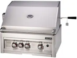
OverallWidth-------------------- 28"
OverallHeight------------------- 26"
Overall Depth-------------------- 25-1/4"
ControlPanelHeight----------- 11-1/8"
Hood Open Size
Counter toTop------------------ 26-1/4"
Overall Depth-------------------- 27"
HoodOverhang----------------- 2”
Cut out Size
Width------------------------------ 25”
Depth------------------------------- 21-3/4”
Height------------------------------ 10-7/8”
GRILL SPEC. & PARTS LIST – SUN3B/SUN3BIR – LP/NG
PAGE 1
Page 45
GRILL SPEC. & PARTS LIST – SUN3B/SUN3BIR – LP/NG
PAGE 2

SUN3B/SUN3B-IR-LP/NGParts List
1 Upper Hood 1 Hood-3B
2 HoodHandle 1 Hood-3B-H
3 HoodThermometer 1 P-TMeter
4 WarmingRack 1 P-WR
5 GrillUpperBack Body 1 P-GUBB
6 LightCover 2 P-Lcover
7 IR Burner(Back Burner) 1 P-IRburner
8 ImpulseIgniterWire 1 P-IIW
9 GrillGrates 2 P-GSet3B
10 Gas ManifoldPipe 1 P-GMP
11 SafetyValve 1 P-SAIvalve
12 Auto-Ignition Valve 1 P-AIvalve
13 Standard Valve 2 P-Rsvalve
14 ImpulseIgniterBox 1 P-IIB
15 SmallKnobRubberBand 1 P-Knob-S-RB
16 SmallKnob 1 P-Knob-S
17 Large KnobRubberBand 3 P-Knob-L-RB
18 LargeKnob 3 P-Knob-L
19 Front ControlPanel 1 P-CP
20 Drip Tray 1 P-Dtray
21 ControlPanelFrame 1 P-CPF
22 I-Burner 3 P-GBurner
23 Flavorizer 3 P-FL-3B
24 Flame Divider 2 P-FDivider
25 GrillBottomSupportFrame 1 P-GBSF
26 LightSwitchBox 1 P-LSB
27
RotisserieRodstowawayBracket
1
P-RRSR
28 SmokerBox 1 P-SMBox
29 Light Transformer 1 P-LT
30 HoodAxle Bolt 2 P-HAB
31 RotisserieHardwareGroup 5 P-RHG
32 Rotisserie Motor 1 P-Rmotor
33 RotisserieFork 2 P-Rfork
34 RotisserieRod 1 P-RR
35 HoodRubberStopper 2 P-HRS
GRILL SPEC. & PARTS LIST – SUN3B/SUN3BIR – LP/NG
SUNSTONE 3 BURNER GRILL
& SUNSTONE 3 BURNER
W/IR GRILL ARE COMBINED
IN THIS LIST
PAGE 3
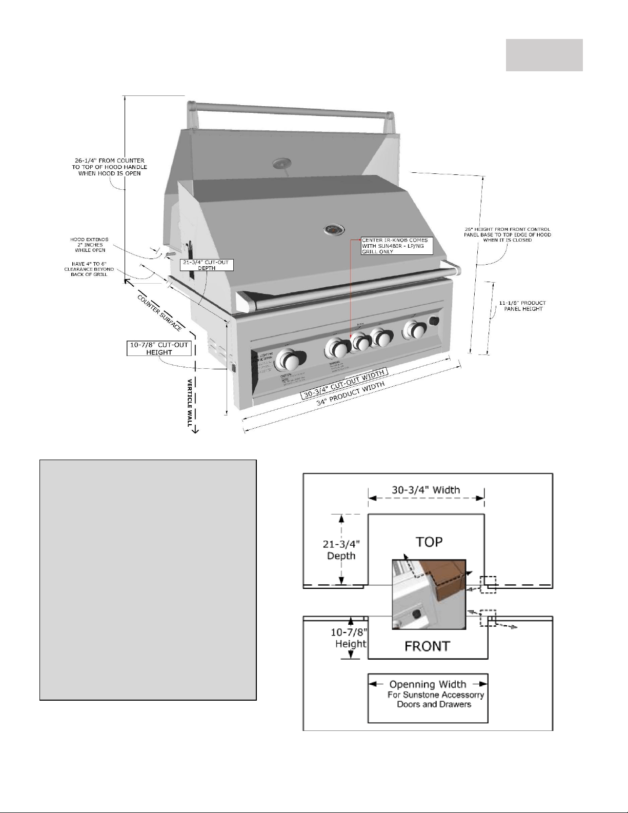
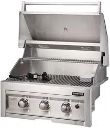
Hood Closed
OverallWidth-------------------- 34"
OverallHeight------------------- 26"
Overall Depth-------------------- 25-1/4"
ControlPanelHeight----------- 11-1/8"
Hood Open Size
Counter toTop------------------ 26-1/4"
Overall Depth-------------------- 27"
HoodOverhang----------------- 2”
Cut out Size
Width------------------------------ 30-3/4”
Depth------------------------------- 21-3/4”
Height------------------------------ 10-7/8”
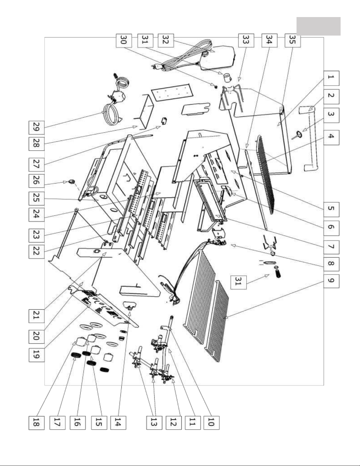
GRILL SPEC. & PARTS LIST – SUN4B/SUN4BIR – LP/NG
PAGE 4

GRILL SPEC. & PARTS LIST – SUN4B/SUN4BIR – LP/NG
PAGE 5
SUN4B-IR-LP/SUN4B-IR-NG Parts List
1 Upper Hood 1 Hood-4B
2 HoodHandle 1 Hood-4B-H
3 HoodThermometer 1 P-TMeter
4 WarmingRack 1 P-WR
5 GrillUpperBack Body 1 P-GUBB
6 LightCover 2 P-Lcover
7 IR Burner(Back Burner) 1 P-IRburner
8 ImpulseIgniterWire 1 P-IIW
9 GrillGrates 2 P-GSet3B
10 Gas ManifoldPipe 1 P-GMP
11 SafetyValve 1 P-SAIvalve
12 Auto-Ignition Valve 1 P-AIvalve
13 Standard Valve 3 P-Rsvalve
14 ImpulseIgniterBox 1 P-IIB
15 SmallKnobRubberBand 1 P-Knob-S-RB
16 SmallKnob 1 P-Knob-S
17 LargeKnobRubberBand 4 P-Knob-L-RB
18 LargeKnob 4 P-Knob-L
19 Front ControlPanel 1 P-CP
20 Drip Tray 1 P-Dtray
21 ControlPanelFrame 1 P-CPF
22 I-Burner 4 P-GBurner
23 Flavorizer 4 P-FL-4B
24 Flame Divider 3 P-FDivder
25 GrillBottomSupportFrame 1 P-GBSF
26 LightSwitchBox 1 P-LSB
27
RotisserieRodstowawayBracket
1
P-RRSR
28 SmokerBox 1 P-SMBox
29 Light transformer 1 P-LT
30 HoodAxle Bolt 2 P-HAB
31 RotisserieHardwareGroup 5 P-RHG
32 Rotisserie Motor 1 P-Rmotor
33 RotisserieFork 2 P-Rfork
34 RotisserieRod 1 P-RR
35 HoodRubberStopper 2 P-HRS
GRILL SPEC. & PARTS LIST – SUN4B/SUN4BIR – LP/NG
SUNSTONE 4 BURNER GRILL
& SUNSTONE 4 BURNER
W/IR GRILL ARE COMBINED
IN THIS LIST
PAGE 6
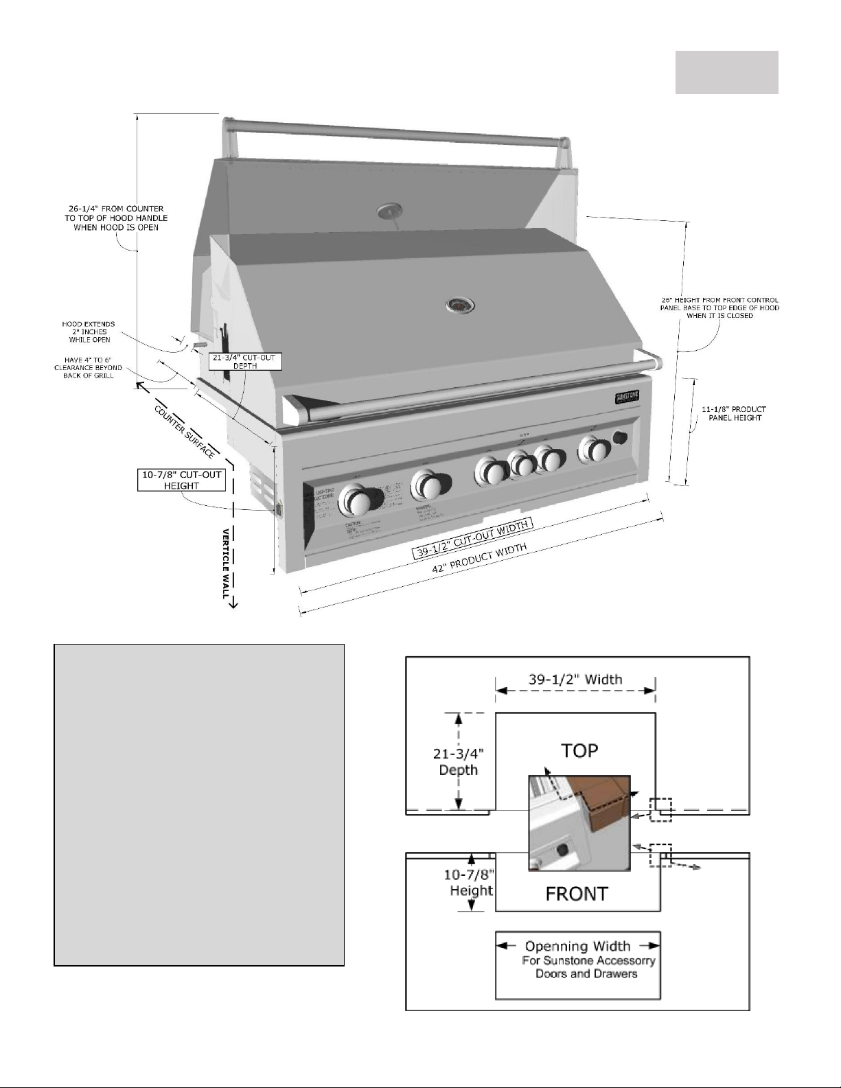
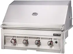
Hood Closed
OverallWidth-------------------- 42"
OverallHeight------------------- 26"
Overall Depth-------------------- 25-1/4"
ControlPanelHeight----------- 11-1/8"
Hood Open Size
Counter toTop------------------ 26-1/4"
Overall Depth-------------------- 27"
HoodOverhang----------------- 2”
Cut out Size
Width------------------------------ 39-1/2”
Depth------------------------------- 21-3/4”
Height------------------------------ 10-7/8”
GRILL SPEC. & PARTS LIST – SUN5BIR – LP/NG
PAGE 7

Page 54
GRILL SPEC. & PARTS LIST – SUN5BIR – LP/NG
PAGE 8
SUN5B-IR-LP/SUN5B-IR-NG Parts List
1 Upper Hood 1 Hood-5B
2 HoodHandle 1 Hood-5B-H
3 HoodThermometer 1 P-TMeter
4 WarmingRack 1 P-WR
5 GrillUpperBack Body 1 P-GUBB
6 LightCover 2 P-Lcover
7 IR Burner(Back Burner) 1 P-IRburner
8 ImpulseIgniterWire 1 P-IIW
9 GrillGrates 3 P-GSet5B
10 Gas ManifoldPipe 1 P-GMP
11 SafetyValve 1 P-SAIvalve
12 Auto-Ignition Valve 1 P-AIvalve
13 Standard Valve 4 P-Rsvalve
14 ImpulseIgniterBox 1 P-IIB
15 SmallKnobRubberBand 1 P-Knob-S-RB
16 SmallKnob 1 P-Knob-S
17 LargeKnobRubberBand 5 P-Knob-L-RB
18 LargeKnob 5 P-Knob-L
19 Front ControlPanel 1 P-CP
20 Drip Tray 1 P-Dtray
21 ControlPanelFrame 1 P-CPF
22 I-Burner 5 P-GBurner
23 Flavorizer 5 P-FL-5B
24 Flame Divider 4 P-FDivder
25 GrillBottomSupportFrame 1 P-GBSF
26 LightSwitchBox 1 P-LSB
27
RotisserieRodstowawayBracket
1
P-RRSR
28 SmokerBox 1 P-SMBox
29 Light PowerBox 1 P-LPB
29 Light transformer 1 P-LT
30 HoodAxle Bolt 2 P-HAB
31 RotisserieHardwareGroup 5 P-RHG
32 Rotisserie Motor 1 P-Rmotor
33 RotisserieFork 2 P-Rfork
34 RotisserieRod 1 P-RR
35 HoodRubberStopper 2 P-HRS
GRILL SPEC. & PARTS LIST – SUN5BIR – LP/NG
PAGE 9

GRILL INSTALLATION – BURNER BOLT REMOVAL
PAGE 10
Why is this Important!
The intensity of the Gas Burners will gradually erode layers of materials of the Stainless-Steel Burners
causing them to eventually Burn-Through, thus causing Flare-Ups. When this happens, you will need to
replace the Burners, and if the Burner Bolts are still attached, they may have Corroded and become
difficult to later remove. By removing these before installation, the burners will be easily removed at any
later time, either for replacement or for annual cleanings.
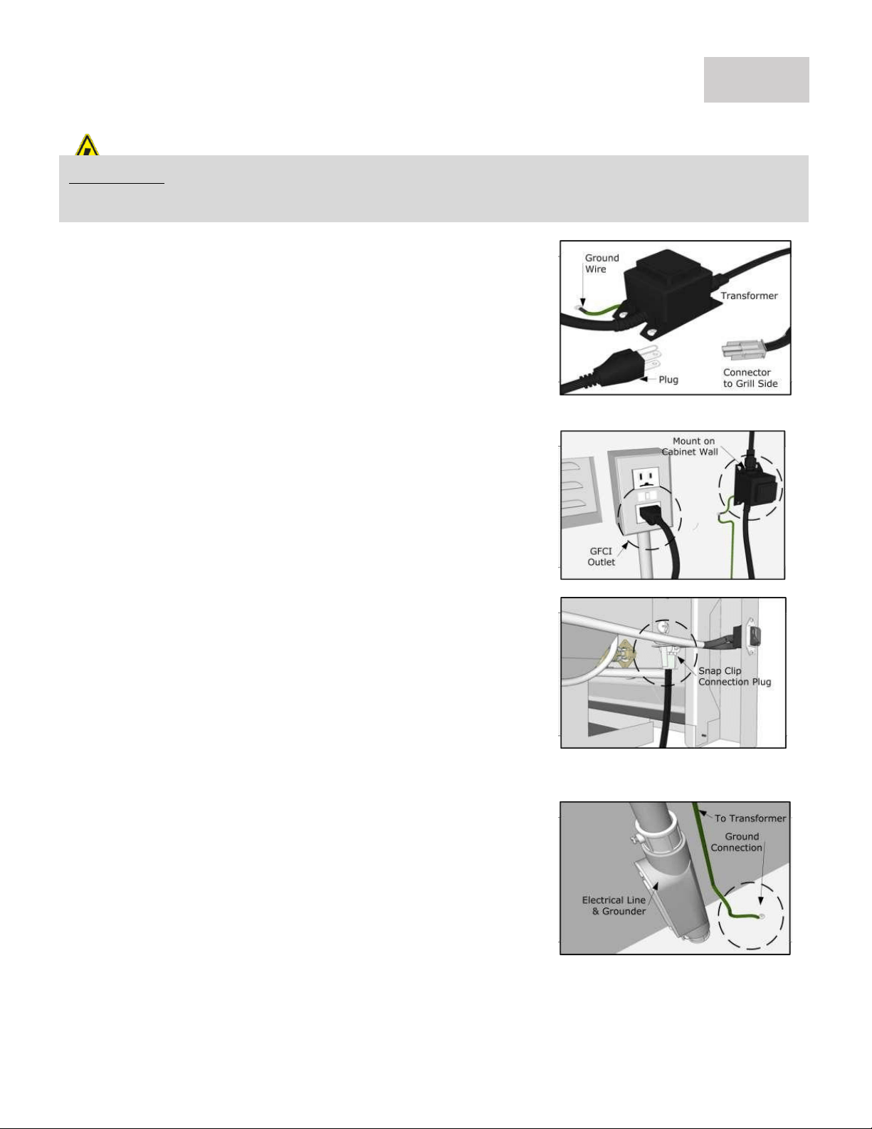
1.Locatethetransformer
Removethetransformerfrom theplasticbaglocated
intheinteriorofgrill.MakesuretheTransformeris
complete,anddouble check thegrilllight plugcordis
properlysecured to transformer,andall wiresare firmly
fixedinto plastic clipplug.
2.MountTransformer
Usingmetalscrews andattach thetransformer tothe
backinnerwallofyourislands cabinetwall, somewhere
near thealready installedGFCIelectrical outlet. When
youplugthetransformerin,double check thenGFCI
breaker switch,that theoutlet has power.
4.MakeConnections
LocatetheLightSwitchonLeftsideof grillcontrol
panel.The Transformer'selectricalconnectionto
grillislocated behindcontrolpanel,next tolight
switch. The connectionclips together toforma
secureconnection.Doublecheck that allwiresare
tightlypushedintoplugsockets, soall wiresmake
properconnections. Youcantuck wireintobodyof
grillorislandframe,soit's upandout of theway.
3.InstalltheGroundWire
Theshortgreenwireextendingfromoffthe
transformerelectricaladapterisrequiredto be
grounded.Dependingonthelocation youdecideto
installtransformer,itmay benecessary toextend
the wireso thatitcanreachagroundingstructure. A
groundingstructureisanysolidstructure that makes
contact with the earth.
LIVE CIRCUIT:Indicates a potentially hazard from Liveelectrical current that if extreme caution is notused,
may result in minor or moderatepersonal injury, or property damage.
GRILL INSTALLATION – GFCI TRANSFORMER FOR LIGHTS
PAGE 11
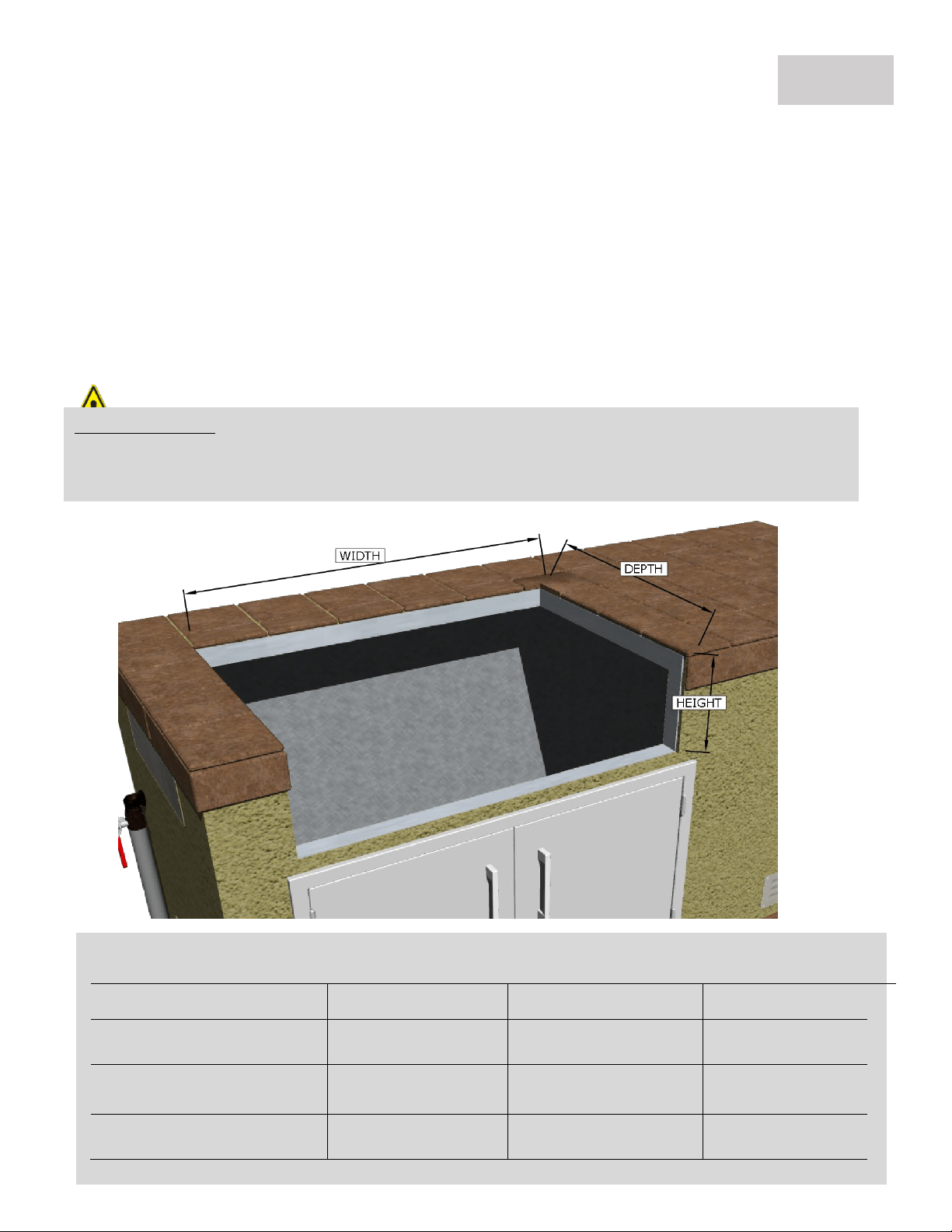
Sunstone Series Grill Island Cut-Out Dimensions
ITEM NO.
WIDTH
DEPTH
HEIGHT
SUN3B/IR – LP/NG
25” Inch
21-3/4” Inch
10-7/8” Inch
SUN4B/IR – LP/NG
30-3/4” Inch
21-3/4” Inch
10-7/8” Inch
SUN5BIR – LP/NG
39-1/2” Inch
21-3/4” Inch
10-7/8” Inch
ATTENTION:Never build shelf or enclose interior space under the BBQ Cut-Out. The Grill is Self-
Rimming and is supported by the top counter surface on the Back and Sides, the front of grill is
designed to Free-Hang. The bottom of Grill needs to be open to allow for proper ventilation.
Grill Cut-Out
Your grill is SELF-RIMMING, meaning the lip of grill rests on top of the counter edge around the cut-out
with the front of grill which is Free-Hanging from counter top. Because of this, there is No Need for any
Trim-Kit like with many other grill in the market.
1. M
a
i
n
t
a
i
n
2
4
”
C
l
e
a
r
a
n
c
e
f
r
o
m
a
n
y
C
o
m
b
u
s
t
i
b
l
e
GRILL INSTALLATION – OVERVIEW & REQUIRMENTS
PAGE 12

InFIG.B,Excess heatleaves throughbackofgrill, butis
blocked by PrevailingWind,causingoverheatingofgrill.
1.Slide GrillinPlace
YourSunstone™ grillisspecially designed with
aninternalbuiltinhangerlip locatedat the
Right,Left andBacksides. Thegrilllipallows it
tohangbythe threesupported edgeson the
right,leftandback. The front controlpanel
requiresnosupportingedge;itisdesigned to
hangdownthefrontofyourcut-out.
2.Allow for Ventilation
YourSunstone™ grillis engineered withspecial
ventsonthebackof unit,whichallowproper
airflow out of thebackofgrill,alsoincreased
airflow intoInfra-redBurnergaschamber. Be
sureyouallow aminimumof 4"behindgrillfor
properairventilation. Slidegrillallthe way into
cut-out,sotherearenogaps present toinside
ofislandframe.
3.SecuringinPlace
Thecontrol panel isdesigned to sit flushagainstthe
islandface. If counter top extends beyondtheislands
face,creatinga countertop overhang, itmust becut
flushwith theislandfacewherethewidthof the
control panelor a gapwillbecreated exposing the
forward portionsof theleftandright-side firewalls.
Also,besuretoallowatleasta1" of clearance below
Drip pan, as given in the cut-out height dimensions.
GRILL INSTALLATION – AIRFLOW & PREVAILING WIND
PAGE 13
ATTENTION:Take special precaution when installing grill in open Breezy area, check the direction of
Prevailing Wind Direction, if back of grill is facing any oncoming wind or breeze, be sure to protect the
back of grill, erect a partition wall, or only use grill with hood open on breezy days.
Windy Conditions
Your grill is specially designed to draw fresh air in through the front, and direct it to the bottom burners.
When grilling the hot gases are then released through the back of grill through a venting system. Using
your grill in windy conditions may disrupt the front-to-back air flow.
1. For breezy days, be careful not to leave the front hood down for more than 15 minutes,when the
burners are on. (Never leave grill unattended when in operation)
2. If you suspect the grill is overheating, using an oven mitt, open the front hood. Thenadjust the
burner control knob to off position.
3. Orient the grill so the Prevailing winds are not blowing into the rear or side of grill.
Windy Area
Positioning your grill in your backyard is more often thought of how it is pleasing to the eye, but more
important than this is how that it functions correctly. Unlike an indoor appliance, your grill has to combat
many outside weather influences in an all manner of weather related instances, most severely is Wind.
4. Maintain proper Prevailing wind, grill direction – with the front of grill facing in to the wind, and
the back of grill in the direct wind is blowing.
5. If direction of wind is unclear, or difficult to combat even with preventative measures, then always
grill with the hood open, and when hood is closed – always be within close proximity to grill and
monitor it that it does not overheat.
6. If wind or breeze is in the direction of back of grill, you must erect partition wall of 14” height so
that the top of grill hood is covered by several inches. If this is not done, you must grill with hood
open and or when hood is closed stand in close area to grill and monitor if the grill overheats.
ISLAND LOCATION – OPEN AREA INSTALL
PAGE 14
ATTENTION:If you do not have a partition wall, always Grill with the Hood Open, and additionally
completely open the bottom Access Doors below the Grill, in order to vent out excess heat buildup.
ATTENTION:All Gas Grill Installations MUST HAVE MINIMUM TWO AIR-FLOW VENTS, either in
ELEVATED POSITION for Natural Gas or LOWERED POSITION for Liquid Propane. Your Warranty may
be VOID if island does not meet basic setup requirements.
Minimum Distances to Combustible Materials or other
Appliance ONLY, Non-Combustible materials do not apply!
From Counter to Overhead Structure
4’ to 6’ ft. Min.
Clearance
From Counter to Outdoor Vent Hood
48" Min. Clearance
From Floor to Counter Top
42" Min. Clearance
From Grill to Vent Hood Width
4”-6" Min. Clearance
From Appliance to Appliance
3" Min. Clearance
From Appliance to Combustible Material
24" Min. Clearance
Clearances to Non-Combustible Construction*:
A minimum of 4” to 6” clearance from the back of the grill to non-combustible construction is required for
the purpose of allowing the lid to open fully. It is desirable to allow at least 6” rear and side clearance to
construction above the cooking surface for counter space. If you’ll be using the rotisserie option, the space
is essential for motor and skewer clearance.
BODILY INJURY:Failure to maintain required clearances creates a fire hazard that may
result in property damage or serious personal injury.
Clearances to Combustible Construction**:
Minimum of 24” from the sides and rear of grill must be maintained to adjacent vertical combustible
construction, above the counter top level. You should take in account that there is a large volume of heat,
and smoke will exhaust from the rear of the grill. This may discolor or damage unprotected areas, do not
install under unprotected combustible construction without using a fire safe ventilation system.
A 24” minimum clearance must be maintained under the counter top to combustible construction. The
clearance can be modified by a use of an insulated jacket.
** DEFINITION OF COMBUSTIBLE MATERIAL - Anymaterials of a building structure or decorative
structure made of wood, compressed paper, plant fibers, vinyl/plastic or other materials that are capable of
transferring heat or being ignited and burned. Such material shall be considered combustible even though flame-
proofed, fire-retardant treated or surface-painted, or plastered.
ISLAND LOCATION – ENCLOSED INSTALL
PAGE 15
ATTENTION:All Gas Grill Installations MUST HAVE MINIMUM TWO AIR-FLOW VENTS, either in
ELEVATED POSITION for Natural Gas or LOWERED POSITION for Liquid Propane. Your Warranty may
be VOID if island does not meet basic setup requirements.
INSTALLATION – Gas Hook-Up
For LP Gas Grills, it is shipped with a LP Medium Pressure Regulator
GAS REQUIREMENTS
Verify the type of gas supply to be used, either NG or LP, and make sure the marking on the appliance
rating sticker agrees with that of the supply. The rating sticker is located on the back of the Gas Manifold
Pipe. Never connect an unregulated gas line to the appliance. You must use the gas regulator provided
with the unit, even if the supply is controlled. An installer-supplied gas shut-off valve must be installed in
an easily accessible location. All pipe sealants must be an approved type and resistant to the actions of LP
gases. Never use pipe sealant on flare fittings. All gas connections should be made by a qualified technician
and in accordance with local codes and ordinances. Gas conversion kits are available from Customer care
by dialing 888-934-9449,press option #1. When ordering gas conversion kits, have the model number, and
the type of gas (natural or LP) from your grill.
BODILY INJURY:Before connecting LP tank to regulator, check that all grill burners and side burners,
smokers, and rotisserie valves are in the OFF position and open grill lid.
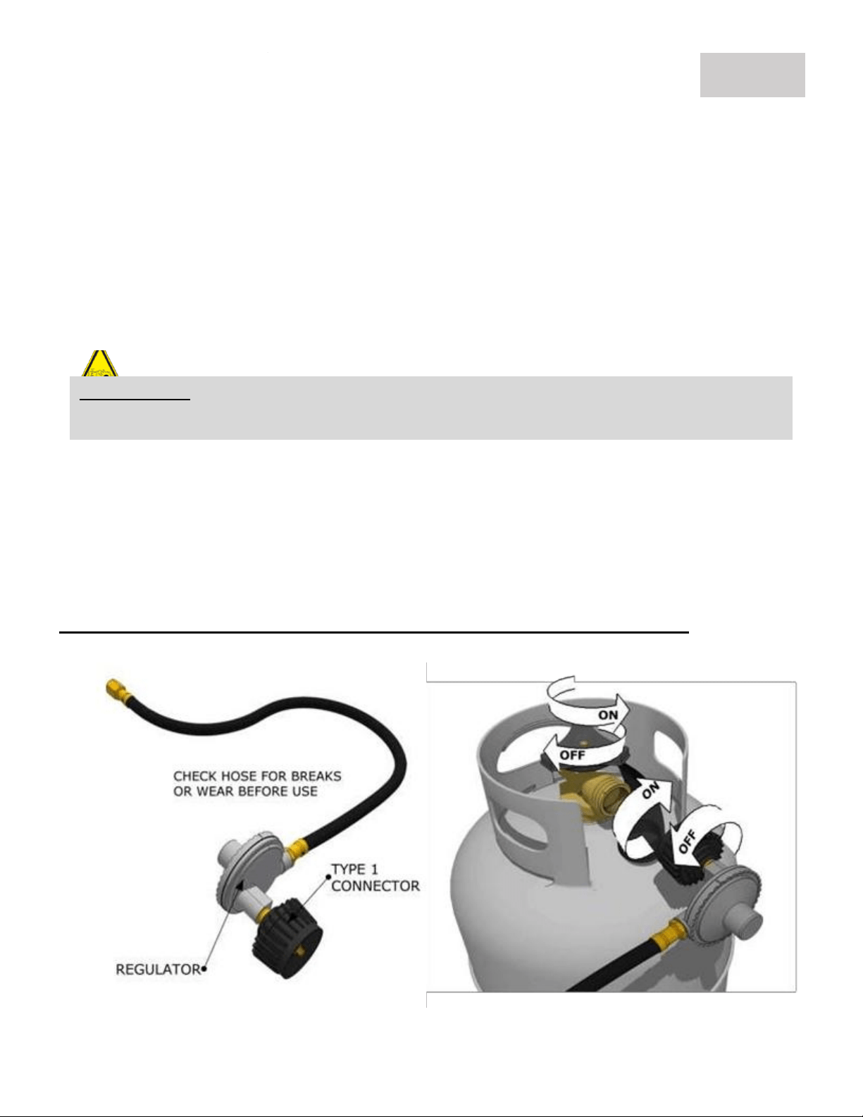
GAS SETUP – LP GAS HOOK-UP
Liquid Propane Gas Hook-Up
TheType1connection system hasthefollowingfeatures:
Thesystemwillnot allow gas
toflowuntilapositiveconnectionhasbeenmade.NOTE:The cylinder controlvalvemustbe turnedoff
beforeany connectionismadeorremoved.Thesystemhasathermalelement that willshut off the flowof gas
intheevent of afire. Thesystemhasaflow limitingdevicewhich,whenactivated,willlimit the
flowofgasto10cubic feet per hour.NEVERusegrill without leak testing.
PAGE 16
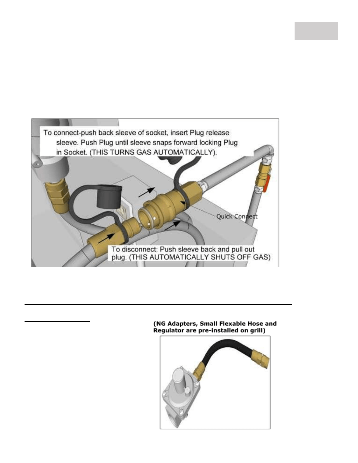
NG Gas Hook-up
NaturalGasgrills isdesigned tooperateonNaturalGasONLY,at apressureregulatedat 7”water
column(W.C.) when equippedwiththe correct naturalgas orificesonthevalves andaNG regulatoron
thesupply lineregulated at theresidentialmeter.
NG Quick Connect Hose Operation
For NG Gas Grills, it is shipped with a NG Medium Pressure Regulator
& 18” long Hose.
GAS SETUP – NG GAS INSTALLATION
PAGE 17

Lighting Instructions
Manual Lighting Instructions:
NOTE: To light gas grill with a gas lighter,make
sure the grill has been leak tested and burners be
properly located. Insert long-necked gas lighter
through the cooking grid, and in through an
adjacent side port hole of the Flavorizer grid,
placing near a burner side. Turn the closest burner
knob on to “HIGH” setting to release gas. Turn on
the button on gas lighter, burner should light
immediately. Adjust burners to desired cooking
temperature.
Open Lid/Hood
Ensure Burner Control Knobs
In the “OFF” position,
Turn on the gas supply valve
1. Push Far-Right burner knob in and
slowly rotate counter-clockwise to the
high position.
2. You will hear a loud click as the
electronic lighter produces a spark. Listen
for the sound of the gas igniting and look
for a flame through the cooking grids. If
the burner does not light on the first try,
repeat immediately.
3. If the burner does not light in 5
seconds then wait five minutes until the
gas clears before attempting to light it
again. Repeat the procedure or try the
manual lighting procedure to the Right.
4. Upon successful lighting, Turn the
Neighboring Burner on, and allow Gas to
Ignite.
5. To shut off the burners, rotate the
knob and turn to OFF.
6. It is normal to hear a popping sound
when the burners are turned off.
EXPLOSION:When Lighting the Grill, Hold the Knob in until Burner Ignites. DO NOT
RELEASE KNOB, GAS WILL CONTINUE TO FLOW. ALWAYS IGNITE GRILL WITH HOOD OPEN!
WARNING:Neverstand withyour headdirectly overtheGrill when lighting theMain Bottom
Burner or Rotisserie Back IR Burner, toprevent possibleinjury.
GRILL START-UP – LIGHTING THE GRILL
PAGE 18
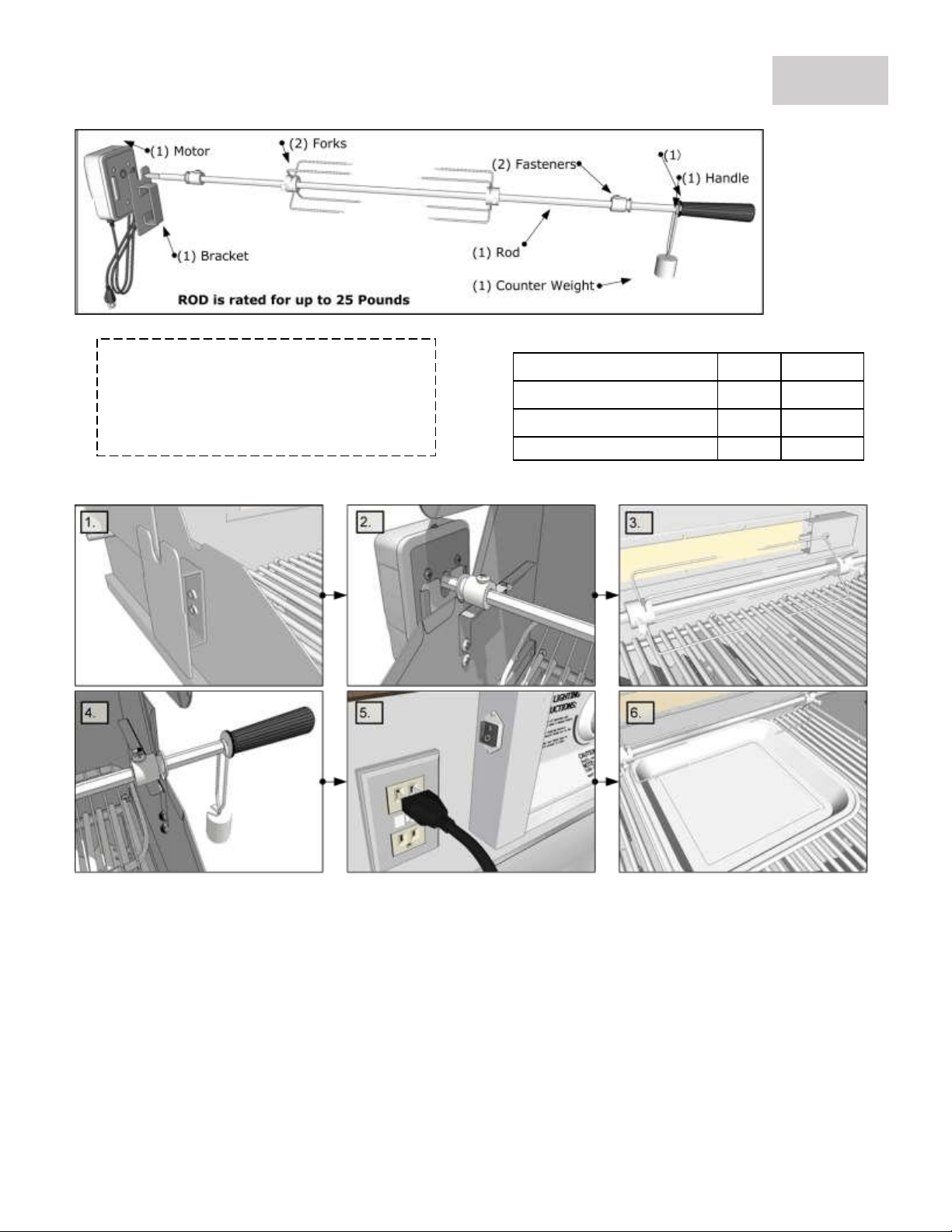
Rotisserieismostlyusedtocook largepiecesofmeatandpoultrytoassureslow, even cooking. The constant
turningprovides aself-bastingaction,making foodcookedonarotisserieexceptionally moist
andjuicy.Rotisseriecookinggenerally requires1 ½to4½hourstocookdependingon thesizeandtypeofmeat
beingcooked.Youcanhaverotisseriecookingwithindirect heatwithinfraredrotisserieburner. Preferredby
professionalchefsoverother methods, theintenseheatisidealforsearinginthenatural
juicesandnutrientsfoundin qualitymeats.Forsuccessfulrotisserie,themeatshouldbecenteredand
balancedasevenlyaspossibleonthespitrod toavoidoverworkingtherotisseriemotor.
1. Attach Motor BracketAssembly tothesideof thebarbecueframe(can bemounted oneitherleft
ortheright sideoftheframe) usingtwoscrews andtwonuts.
2. InsertRotisserie MotorontoMotor BracketAssembly.
3. SlideProngForks withthe prongsfacingawayfrom thehandleontotheSpitRod. So that any
food itemwillbeinthe centerbetweenthetwo fourprongforks.
4. AssembleKeyWasher,Counter-balanceandhandletoSpit Rod. SlideShaftCollarwithlongend
towardshandle.
5. Insert motorextensioncord three prong plugintoan adjacent grounded GFCIreceptacleoutlet.
6. Beforeplacingfooditemonforks whentherotisserieisbeingoperated exclusively,itisstrongly
recommended that apanbe placed onthegrillinggrids,beneaththefoodto catchthemeat
drippings. Thiswillprevent excessivebuildupofdrippingsonthegrids andfacilitatecleaning.
When fooditemisplacedonrotisserie,besurethat allBoltsare tightenedsecurely.
NOTE:ClosehoodcarefullyandalignMotorBracketandShaft MountingBracketsothat RotisserieRod isin
betweenthe hoodopenings.
Lightingtherotisserieburner
1. Grillsurface burnersshouldbe offfor rotisserie cooking
2. MakesureRotisseriemotorisplugged in toGFCIoutletand turnit on.
3. Meat should be centeredandbalancedontherotisseriespit rodforefficient cooking.
4. Usea drippan under themeat to catchanyjuices
5. Keephoodclosedwhen cookingwiththerotisserie
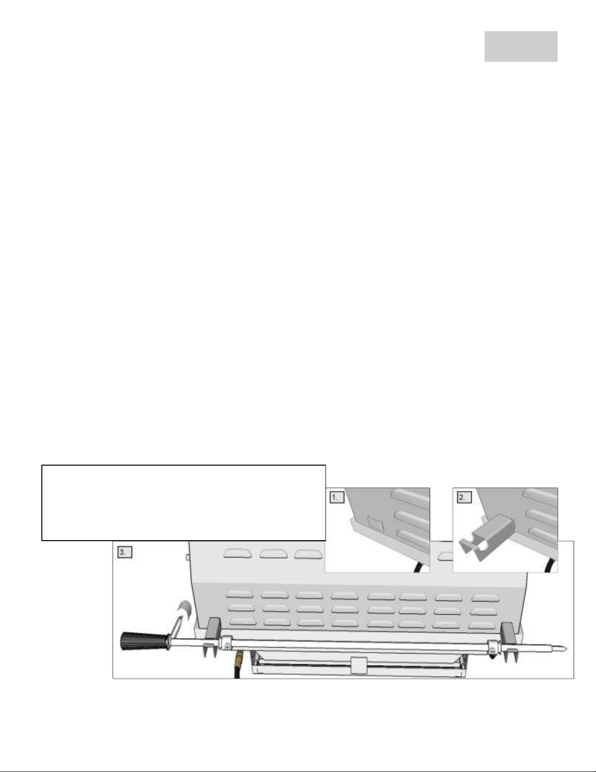
Optional RotisserieRodStow-Away
1. Locatetwoleftandrightnotches atbackof grill.
2. Locatetworemovable brackets,andhookinplace.
3. Un-mountRotisserieRodfromgrill,onlyremoving
the Forks,andliftRod overtopandplaceinbrackets.
GRILL START-UP – ROTISSERIE ROD SETUP
PAGE 19
Name
Qty.
PartNo.
3BurnerRotisserieset
1
P--RK-3B
4BurnerRotisserieset
1
P--RK-4B
5BurnerRotisserieset
1
P--RK-5B
Rotisserieassemblycanbepurchased
individuallyeither byindividualitem, or ina
completeset,foryour sizeof grill.Therotisserie
assemblycanalso beusedwith or withoutan
infra-red backburner.
ElectricalGroundingInstructions:
Therotisseriemotorisequippedwithathree-pronggroundingplugforyourprotectionagainstelectric
shock.Thisplugmustbeinserted directlyintoa properlygroundedthree-prongreceptacle.Do not cut
orremovethegroundingprongfromthisplug.
Therotisseriemotormust beelectrically groundedin accordancewithlocalcodesor,intheabsenceof
localcodes,in accordancewiththeNationalElectricalCode,ANSI/NFPA70-1990 orCanadianElectrical
Code,CSA C22.1.
GRILL START-UP – ROTISSERIE ROD SETUP
PAGE 20
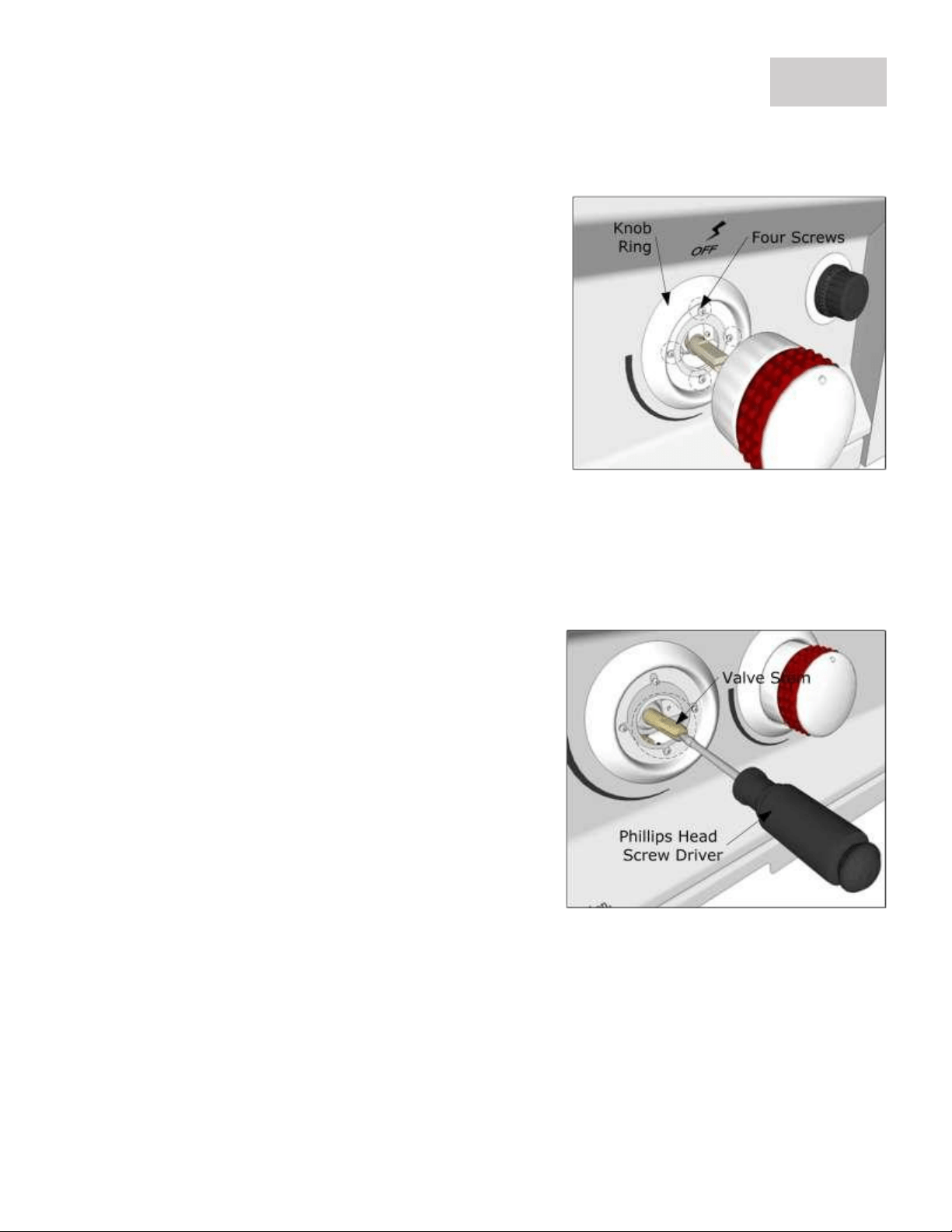
MAINTANCE –Knob & Ring Adjustment
Knob &RingAdjustment
Whileturninganyof the knobsandyounoticeany onestickingorrubbing,Followthesesteps.
1. Turn each knobforany issues
2. Forknobthat rubs orsticks wheneither turned or
pushedin,removeknobandunscrewthe fourscrews
slightly,soringisloosened. (DONOTREMOVESCREWS
COMPLETLEY)
3. ReplaceKnobbackon,MoveKnobRingLeft,Right,Up,
andDown, tillit isCenteredaroundKnob,thenremove
knob,while holdingringinplace.
4. Fasten allfourscrews tightly inplace,andreplace knob
backonvalvestem.Do thisuntil knob turnsfreely, and
when pushedin,releases properly.
Knob &ValveAdjustment
Whileturninganyof the knobs, andyounoticeany areloose,anddoesnoteitherturngason,or turnoff
properlyandoreitheroneAuto-Ignition Knob does notignite burner,follow thesesteps.
1. Turn each knobforany issues
2. Forknobthat isloose,removeknob,andcheck tosee
iftheinsideblackplasticguts arepartiallydamaged.
(IFDAMAGETOKNOBISNOTICED,CONTACT
SUNSTONEFORKNOBREPLACEMENTBEFORE
PROCEEDING)
3. WithKnobremoved,usePhillips Flat-HeadScrew
Driver,andvery slightlypushtipintovalveslitat the
headof ValveStem,toseparatetwosides,and push
them further apart.(DONOTPUSH TOOHARD,OR
VAVLESTEM WILL SNAP, ONLY1/16" TO1/8"INIS
USUALLYNEEDED)
4. ReplaceKnobbackonValveStem
Youshould notice
Knobismuchtighter onValve,andturns gasflowon/off Donot usean
extensioncordtosupplypowertoyourgrill. Suchusemay result infire, electricalshock orother
personalinjury.Donot installa fuseinthe neutralorground circuit. Afusein theneutralor groundcircuitmay result
inanelectricalshock hazard.Donotgroundthisappliancetoagas supplypipe orhotwater pipe.
GRILL START-UP – KNOB MAINTANCE
PAGE 21

WARRANTY COVERS ORIGINAL PURCHASER ONLY, MUST HAVE COPY OF ORIGINAL INVOICE
TO RECEIVE ALL WARRANTIES.
WARRANTY ON PARTS_________________________________________________________________________
MAIN BURNERS ------------------------------------------ LIMITED LIFTIME, with ONE TIME REPLACEMENT
COOKING GRATES --------------------------------------- LIMITED LIFETIME
FLAVORIZER GRIDS --------------------------------------LIMITED LIFETIME
FIREBOX & COMPONENTS -----------------------------LIMITED LIFETIME
VALVES, KNOBS, LIGHTS & ALL OTHER PARTS -----1 YEAR WARRANTY
LIMITED LIFETIME WARRANTY
Stainless steel burner, Cooking Grids, Flavorizer Grids, Stainless Steel Housings (including liners, frames, ovens and barbecue
faces), to be from defects in material and workmanship when subjected to normal domestic use and service for the lifetime
of the original purchaser. This warranty does not include discoloration, surface corrosion, Burn Through and scratches which
may occur during regular use. (See supporting burner Limited Lifetime, with One Time Replacement Warranty below)
LIMITED LIFETIME BURNER WARRANTY – W/ONE TIME REPLACEMENT
This warranty covers the burner for the Lifetime of the Grill with a One Time Replacement against surface corrosion and Burn
Through, which is the most common reason for replacement of this part, and is what most other manufactures do not cover
for. The most common reason this occurs when using High Cooking Temperatures, Excessive Humidity, Chlorine, and Salt that
can affect the stainless-steel components. This warranty does not cover the burner in Commercial or Residential
Communities, also for negligent use or misuse of the product, use with improper fuel/gas supply, improper installation of grill
– including islands with NO Ventilations, must have minimum of Two Vents for each Gas Grill Appliance, High for Natural
Gas, or Low for Liquid Propane and use contrary with operating instructions.
LIMITED ONE-YEAR WARRANTY
All other grill components including knobs, valves, tubing, light assembly, and covers are warranted to be free
from defects in material and workmanship for a period of one year from the original date of purchase.
LIMITATIONS & EXCLUSIONS
1. Your Sunstone Grill MUST MEET MINIMUM SETUP REQUIRMENTS or your warranty may be VOID!
2. SUNSTONE GRILL warranty applies only to the original purchaser and may not be transferred.
3. SUNSTONE GRILL warranty is in lieu of all other warranties expressed or implied and all other obligations
or liabilities related to the sale or use of its grill products.
4. SUNSTONE GRILL warranty shall not apply and SUNSTONE METAL PRODUCTS LLC. Is not responsible for
damage resulting from misuse, abuse, alteration of or tampering with the appliance, accident, hostile
environment, flare-up fires, improper installation, or installation not in accordance with the instructions
contained in the User Manual, or the local codes.
5. SUNSTONE METAL PRODUCTS LLC. shall not be liable for incidental, consequential, special or contingent
damages resulting from its breach of this written warranty or any implied warranty.
6. Some states do not allow limitations on how long an implied warranty lasts, or the exclusions of or
limitations on Consequential damages. This warranty gives you specific legal rights and you may have
other rights, which vary from state to state.
7. No one has the authority to add to or vary SUNSTONE GRILL warranty, or to create for SUNSTONE METAL
PRODUCTS LLC. any other obligation or liability in connection with the sale or use of its products.
WHAT IS NOT COVERED& INTERNET PURCHASE DISCLAIMER
1. Shall not be responsible for and shall not pay for the following Installation or start-up.
2. Service by an unauthorized service provider;
3. Damage or repair due to service by an unauthorized service provider or use of unauthorized parts.
4. Damage caused by accidents, abuse, alteration, misuse, installation that is not in accordance with the
instructions contained in the User Manual, or local codes.
5. To correct normal adjustments or settings, due to improper installation, commissioning or local gas
supply properties.
6. Shipping and handling costs, export duties, or installation cost.
7. The cost of service calls to diagnose trouble; or Removal or re-installation cost.
SUNSTONE GRILL NON-TRANSFERABLE WARRANTY
PAGE 22