

Contents
1 INTRODUCTION ........................................................................................ 3
2 SAFETY INFORMATION ............................................................................. 5
3 INSTALLATION MATERIAL ......................................................................... 8
3.1 Kit supplied with dishwasher ...................................................................... 9
4 DIMENSIONS OF DISHWASHER ............................................................. 10
5 INSTALLATION AND HOOK-UP ............................................................... 11
5.1 Leveling .................................................................................................... 12
5.2 Connections ............................................................................................. 13
5.2.1 Connecting to the water supply ................................................................ 14
5.2.1.1 Connecting to the water tap ..................................................................... 15
5.2.1.2 Connecting the drain hose ....................................................................... 16
5.2.2 Electrical connections and warnings ......................................................... 22
5.3 Commissioning ........................................................................................ 23
5.3.1 Installation procedure ............................................................................... 23
5.3.2 Procedure for mounting the door panel .................................................... 25
5.3.3 Completion of installation ......................................................................... 28
5.4 Testing ..................................................................................................... 31
EN
CONTENTS
1

NO I T CUDOR T N I1
Thank you for choosing one of our products. To install this dish-
washer correctly and safely, please read this manual carefully. The
manual is divided into sections giving you a step-by-step guide to
installation of the appliance. The texts are easy to understand and
are complete with detailed illustrations. This user-friendly manual will
provide answers to all your questions about installation of the dish-
washer.
This manual comprises the following sections:
INTRODUCTION: general information about the manual.
WARNINGS: a list of warnings concerning safety during installation.
INSTALLATION INSTRUCTIONS: for the qualified technician who
must carry out the installation, hook-up and testing of the appli-
ance.
Nomenclature of figures and tables:
The progressive number of each figure is shown in the bottom right-
hand corner of the relative box. An example of a progressive number
is “Fig. 4-01”, where the first number (4) indicates the section to
which the figure belongs, while the second number (01) indicates
the progressive number of the figure in section 4 (Fig. 4-01 is the
first figure in section 4). The tables are numbered in the same way,
bearing in mind that “Tab.” is used instead of “Fig.” (e.g.: Tab. 4-01
is the first table in section 4). If a table occupies more than one page,
a letter is added after the progressive number (e.g.: “Tab. 4-01a”,
Tab. 4-01b”).
EN
CONTENTS
2

NO I T CUDOR T N I1
Thank you for choosing one of our products. To install this dish-
washer correctly and safely, please read this manual carefully. The
manual is divided into sections giving you a step-by-step guide to
installation of the appliance. The texts are easy to understand and
are complete with detailed illustrations. This user-friendly manual will
provide answers to all your questions about installation of the dish-
washer.
This manual comprises the following sections:
INTRODUCTION: general information about the manual.
WARNINGS: a list of warnings concerning safety during installation.
INSTALLATION INSTRUCTIONS: for the qualified technician who
must carry out the installation, hook-up and testing of the appli-
ance.
Nomenclature of figures and tables:
The progressive number of each figure is shown in the bottom right-
hand corner of the relative box. An example of a progressive number
is “Fig. 4-01”, where the first number (4) indicates the section to
which the figure belongs, while the second number (01) indicates
the progressive number of the figure in section 4 (Fig. 4-01 is the
first figure in section 4). The tables are numbered in the same way,
bearing in mind that “Tab.” is used instead of “Fig.” (e.g.: Tab. 4-01
is the first table in section 4). If a table occupies more than one page,
a letter is added after the progressive number (e.g.: “Tab. 4-01a”,
Tab. 4-01b”).
NO I T CUDOR T N I 1
Thank you for choosing one of our products. To install this dish-
washer correctly and safely, please read this manual carefully. The
manual is divided into sections giving you a step-by-step guide to
installation of the appliance. The texts are easy to understand and
are complete with detailed illustrations. This user-friendly manual will
provide answers to all your questions about installation of the dish-
washer.
This manual comprises the following sections:
INTRODUCTION: general information about the manual.
WARNINGS: a list of warnings concerning safety during installation.
INSTALLATION INSTRUCTIONS: for the qualifi ed technician who
must carry out the installation, hook-up and testing of the appli-
ance.
Nomenclature of fi gures and tables:
The progressive number of each fi gure is shown in the bottom right-
hand corner of the relative box. An example of a progressive number
is “Fig. 4-01”, where the fi rst number (4) indicates the section to
which the fi gure belongs, while the second number (01) indicates
the progressive number of the fi gure in section 4 (Fig. 4-01 is the
fi rst fi gure in section 4). The tables are numbered in the same way,
bearing in mind that “Tab.” is used instead of “Fig.” (e.g.: Tab. 4-01
is the fi rst table in section 4). If a table occupies more than one page,
a letter is added after the progressive number (e.g.: “Tab. 4-01a”,
Tab. 4-01b”).
EN
3
INTRODUCTION
Symbols used in this manual
(see tab. 1-01)
DANGER. This symbol highlights information and warnings which,
if not observed, may compromise personal safety or damage the
appliance.
DANGER OF ELECTROCUTION. This symbol highlights information
and warnings of an electrical nature which, if not observed, may
compromise personal safety or damage the appliance.
This symbol highlights general information and warnings.
Tab. 1-01
NO I TAMROFN IYTEFAS2
: ECNA I L PPAEHTFOTRAPLARGE TN INASMROFL AUNAMS I HT
IT MUST ALWAYS BE KEPT INTACT TOGETHER WITH THE DISH-
WASHER. BEFORE USING THE APPLIANCE, CAREFULLY READ
ALL THE INSTRUCTIONS CONTAINED IN THIS MANUAL.
INSTALLATION MUST BE PERFORMED BY A QUALIFIED TECH-
NICIAN, IN COMPLIANCE WITH THE REGULATIONS IN FORCE.
THIS APPLIANCE IS INTENDED FOR DOMESTIC USE AND SIMI-
LAR APPLICATIONS SUCH AS THE STAFF KITCHENS OF SHOPS,
OFFICES AND OTHER WORKPLACES, INSTITUTIONS, AND FOR
THE USE OF GUESTS AT HOTELS, HOSTELS, BED AND BREAK-
FAST ESTABLISHMENTS AND OTHER RESIDENTIAL FACILITIES
AND COMPLIES WITH DIRECTIVES 2006/95/EC AND 2004/108/
EC CURRENTLY IN FORCE, INCLUDING THE PREVENTION AND
ELIMINATION OF RADIO FREQUENCY INTERFERENCE.
THE APPLIANCE IS DESIGNED FOR THE FOLLOWING PUR-
POSE: WASHING AND DRYING OF DISHES; ANY OTHER USE
SHALL BE CONSIDERED IMPROPER. THE MANUFACTURER
DECLINES ALL RESPONSIBILITY FOR USES OTHER THAN
THOSE DESCRIBED ABOVE.
- REPEBT SUMGN I C I VRESDNASR I A PER, NO I T A L L A T SN I
FORMED BY QUALIFIED AND AUTHORIZED TECHNICIANS.
AS WELL AS INVALIDATING THE WARRANTY, WORK CARRIED
OUT BY UNAUTHORIZED PERSONS MAY GENERATE HAZARDS.
INSTALLATION MUST BE PERFORMED IN COMPLIANCE WITH
ALL THE DIRECTIVES IN FORCE IN THE COUNTRY OF INSTALLA-
TION AND, IF THESE DO NOT EXIST: IN THE UNITED STATES THE
NATIONAL ELECTRIC CODE; IN CANADA THE CANADIAN ELEC-
TRIC CODE C22.1 - LATEST EDITION/PROVINCIAL AND MUNICI-
PAL CODES AND/OR LOCAL CODES.
THE NAME PLATE FEATURING THE TECHNICAL DATA, SERIAL
NUMBER AND MARKINGS IS VISIBLY POSITIONED ON THE IN-
NER EDGE OF THE DOOR. THE NAMEPLATE ON THE INNER
EDGE OF THE DOOR MUST NEVER BE REMOVED.
- ARAC, S T AOBNOESUROFE L BA T I USTONS I ECNA I L PPAS I HT
VANS OR THE LIKE. DISHWASHERS CERTIFIED FOR DOMESTIC
USE ARE NOT SUITABLE FOR AUTHORISED FOOD FACTORIES.
EN
4
INTRODUCTION
Symbols used in this manual
(see tab. 1-01)
DANGER. This symbol highlights information and warnings which,
if not observed, may compromise personal safety or damage the
appliance.
DANGER OF ELECTROCUTION. This symbol highlights information
and warnings of an electrical nature which, if not observed, may
compromise personal safety or damage the appliance.
This symbol highlights general information and warnings.
Tab. 1-01
NO I TAMROFN IYTEFAS2
: ECNA I L PPAEHTFOTRAPLARGE TN INASMROFL AUNAMS I HT
IT MUST ALWAYS BE KEPT INTACT TOGETHER WITH THE DISH-
WASHER. BEFORE USING THE APPLIANCE, CAREFULLY READ
ALL THE INSTRUCTIONS CONTAINED IN THIS MANUAL.
INSTALLATION MUST BE PERFORMED BY A QUALIFIED TECH-
NICIAN, IN COMPLIANCE WITH THE REGULATIONS IN FORCE.
THIS APPLIANCE IS INTENDED FOR DOMESTIC USE AND SIMI-
LAR APPLICATIONS SUCH AS THE STAFF KITCHENS OF SHOPS,
OFFICES AND OTHER WORKPLACES, INSTITUTIONS, AND FOR
THE USE OF GUESTS AT HOTELS, HOSTELS, BED AND BREAK-
FAST ESTABLISHMENTS AND OTHER RESIDENTIAL FACILITIES
AND COMPLIES WITH DIRECTIVES 2006/95/EC AND 2004/108/
EC CURRENTLY IN FORCE, INCLUDING THE PREVENTION AND
ELIMINATION OF RADIO FREQUENCY INTERFERENCE.
THE APPLIANCE IS DESIGNED FOR THE FOLLOWING PUR-
POSE: WASHING AND DRYING OF DISHES; ANY OTHER USE
SHALL BE CONSIDERED IMPROPER. THE MANUFACTURER
DECLINES ALL RESPONSIBILITY FOR USES OTHER THAN
THOSE DESCRIBED ABOVE.
- REPEBT SUMGN I C I VRESDNASR I A PER, NO I T A L L A T SN I
FORMED BY QUALIFIED AND AUTHORIZED TECHNICIANS.
AS WELL AS INVALIDATING THE WARRANTY, WORK CARRIED
OUT BY UNAUTHORIZED PERSONS MAY GENERATE HAZARDS.
INSTALLATION MUST BE PERFORMED IN COMPLIANCE WITH
ALL THE DIRECTIVES IN FORCE IN THE COUNTRY OF INSTALLA-
TION AND, IF THESE DO NOT EXIST: IN THE UNITED STATES THE
NATIONAL ELECTRIC CODE; IN CANADA THE CANADIAN ELEC-
TRIC CODE C22.1 - LATEST EDITION/PROVINCIAL AND MUNICI-
PAL CODES AND/OR LOCAL CODES.
THE NAME PLATE FEATURING THE TECHNICAL DATA, SERIAL
NUMBER AND MARKINGS IS VISIBLY POSITIONED ON THE IN-
NER EDGE OF THE DOOR. THE NAMEPLATE ON THE INNER
EDGE OF THE DOOR MUST NEVER BE REMOVED.
- ARAC, S T AOBNOESUROFE L BA T I USTONS I ECNA I L PPAS I HT
VANS OR THE LIKE. DISHWASHERS CERTIFIED FOR DOMESTIC
USE ARE NOT SUITABLE FOR AUTHORISED FOOD FACTORIES.
Symbols used in this manual
(see tab. 1-01)
DANGER. This symbol highlights information and warnings which,
if not observed, may compromise personal safety or damage the
appliance.
DANGER OF ELECTROCUTION. This symbol highlights information
and warnings of an electrical nature which, if not observed, may
compromise personal safety or damage the appliance.
This symbol highlights general information and warnings.
Tab. 1-01
NO I TAMROFN I YTEFAS 2
: ECNA I L PPA EHT FO TRAP L ARGE TN I NA SMROF L AUNAM S I HT
IT MUST ALWAYS BE KEPT INTACT TOGETHER WITH THE DISH-
WASHER. BEFORE USING THE APPLIANCE, CAREFULLY READ
ALL THE INSTRUCTIONS CONTAINED IN THIS MANUAL.
INSTALLATION MUST BE PERFORMED BY A QUALIFIED TECH-
NICIAN, IN COMPLIANCE WITH THE REGULATIONS IN FORCE.
THIS APPLIANCE IS INTENDED FOR DOMESTIC USE AND SIMI-
LAR APPLICATIONS SUCH AS THE STAFF KITCHENS OF SHOPS,
OFFICES AND OTHER WORKPLACES, INSTITUTIONS, AND FOR
THE USE OF GUESTS AT HOTELS, HOSTELS, BED AND BREAK-
FAST ESTABLISHMENTS AND OTHER RESIDENTIAL FACILITIES
AND COMPLIES WITH DIRECTIVES 2006/95/EC AND 2004/108/
EC CURRENTLY IN FORCE, INCLUDING THE PREVENTION AND
ELIMINATION OF RADIO FREQUENCY INTERFERENCE.
THE APPLIANCE IS DESIGNED FOR THE FOLLOWING PUR-
POSE: WASHING AND DRYING OF DISHES; ANY OTHER USE
SHALL BE CONSIDERED IMPROPER. THE MANUFACTURER
DECLINES ALL RESPONSIBILITY FOR USES OTHER THAN
THOSE DESCRIBED ABOVE.
- REP EB T SUM GN I C I VRES DNA SR I A PER , NO I T A L L A T SN I
FORMED BY QUALIFIED AND AUTHORIZED TECHNICIANS.
AS WELL AS INVALIDATING THE WARRANTY, WORK CARRIED
OUT BY UNAUTHORIZED PERSONS MAY GENERATE HAZARDS.
INSTALLATION MUST BE PERFORMED IN COMPLIANCE WITH
ALL THE DIRECTIVES IN FORCE IN THE COUNTRY OF INSTALLA-
TION AND, IF THESE DO NOT EXIST: IN THE UNITED STATES THE
NATIONAL ELECTRIC CODE; IN CANADA THE CANADIAN ELEC-
TRIC CODE C22.1 - LATEST EDITION/PROVINCIAL AND MUNICI-
PAL CODES AND/OR LOCAL CODES.
THE NAME PLATE FEATURING THE TECHNICAL DATA, SERIAL
NUMBER AND MARKINGS IS VISIBLY POSITIONED ON THE IN-
NER EDGE OF THE DOOR. THE NAMEPLATE ON THE INNER
EDGE OF THE DOOR MUST NEVER BE REMOVED.
- ARAC , S T AOB NO E SU ROF E L BA T I US TON S I ECNA I L PPA S I HT
VANS OR THE LIKE. DISHWASHERS CERTIFIED FOR DOMESTIC
USE ARE NOT SUITABLE FOR AUTHORISED FOOD FACTORIES.
EN
5
WARNINGS
FO NO I TCE TORP DNA YCNEUQERF , EGA T LOV EHT T AHT KCEHC
THE DOMESTIC MAINS POWER SUPPLY MATCH THE RATINGS
ON THE NAME PLATE OF THE APPLIANCE.
TWO PEOPLE WEARING SAFETY GLOVES ARE REQUIRED
TO LIFT THE DISHWASHER.
- USNU S L A I R E T AM GN I GAKCA P DEDRACS I D GN I V A E L TON OD
PERVISED WITHIN THE HOME. SEPARATE THE VARIOUS PACK-
AGING MATERIALS AND TAKE THEM TO THE NEAREST SORTED
WASTE COLLECTION CENTRE. KEEP CHILDREN, PHYSICALLY
AND/OR MENTALLY IMPAIRED ADULTS, AND ANIMALS AWAY
FROM PACKAGING WASTE; DANGER OF SUFFOCATION.
BEFORE PROCEEDING WITH INSTALLATION, DISCONNECT THE
MAINS POWER SUPPLY FROM THE WORK AREA.
DURING INSTALLATION, TAKE CARE NOT TO INJURE YOURSELF
ON THE SHARP EDGES OF THE APPLIANCE; WEAR SAFETY
GLOVES.
- NOC DNUORG A H T I W D E D I VOR P E B T SUM ECNA I L P P A E H T
NECTION IN ACCORDANCE WITH THE ELECTRICAL SAFETY
REGULATIONS IN FORCE. IF IN DOUBT, HAVE THE SYSTEM
CHECKED BY A QUALIFIED ELECTRICIAN.
THE MANUFACTURER DECLINES ALL RESPONSIBILITY FOR
DAMAGE TO PERSONS OR PROPERTY RESULTING FROM
THE FAILURE TO GROUND THE APPLIANCE OR FROM A DE-
FECTIVE GROUND CONNECTION.
DO NOT USE APPLIANCES WHICH HAVE BEEN DAMAGED DUR-
ING TRANSIT! IF IN DOUBT, CONSULT YOUR DEALER. THE APPLI-
ANCE MUST BE INSTALLED AND CONNECTED IN ACCORDANCE
WITH THE INSTRUCTIONS PROVIDED BY THE MANUFACTURER
OR BY A QUALIFIED TECHNICIAN.
RE TUO EHT L LA SSE LNU REHSAWHS I D EHT E T AREPO TON OD
PANELS HAVE BEEN POSITIONED CORRECTLY.
IMMEDIATELY AFTER INSTALLATION, BRIEFLY TEST THE APPLI-
ANCE FOLLOWING THE INSTRUCTIONS INDICATED BELOW. IF
THE DISHWASHER FAILS TO OPERATE CORRECTLY, DISCON-
NECT IT FROM THE ELECTRICAL POWER SUPPLY AND CALL THE
NEAREST TECHNICAL SERVICE CENTRE. DO NOT ATTEMPT TO
REPAIR THE APPLIANCE.
DO NOT USE EXTENSION CORDS, ADAPTORS OR SHUNT CON-
NECTIONS IN ORDER TO AVOID THE POSSIBILITY OF OVER-
HEATING OR BURNING, WITH CONSEQUENT FIRE HAZARD.
THE MANUFACTURER DECLINES ALL RESPONSIBIL-
ITY FOR DAMAGE TO PERSONS, ANIMALS OR PROPER-
TY RESULTING FROM FAILURE TO OBSERVE THE ABOVE
PRECAUTIONS, FROM TAMPERING WITH EVEN A SINGLE
COMPONENT OF THE APPLIANCE, OR FROM THE USE OF
UNORIGINAL SPARE PARTS.
IF IN DOUBT ABOUT THE CONTENTS OF THIS MANUAL,
CONTACT THE TECHNICAL ASSISTANCE SERVICE.
EN
6
WARNINGS

FONO I TCE TORPDNA YCNEUQERF , EGA T LOV EHTT AHTKCEHC
THE DOMESTIC MAINS POWER SUPPLY MATCH THE RATINGS
ON THE NAME PLATE OF THE APPLIANCE.
TWO PEOPLE WEARING SAFETY GLOVES ARE REQUIRED
TO LIFT THE DISHWASHER.
- USNUS L A I RE T AM GN I GAKCA PDEDRACS I D GN I V A E LTON OD
PERVISED WITHIN THE HOME. SEPARATE THE VARIOUS PACK-
AGING MATERIALS AND TAKE THEM TO THE NEAREST SORTED
WASTE COLLECTION CENTRE. KEEP CHILDREN, PHYSICALLY
AND/OR MENTALLY IMPAIRED ADULTS, AND ANIMALS AWAY
FROM PACKAGING WASTE; DANGER OF SUFFOCATION.
BEFORE PROCEEDING WITH INSTALLATION, DISCONNECT THE
MAINS POWER SUPPLY FROM THE WORK AREA.
DURING INSTALLATION, TAKE CARE NOT TO INJURE YOURSELF
ON THE SHARP EDGES OF THE APPLIANCE; WEAR SAFETY
GLOVES.
- NOCDNUORGAHT I WD E D I VOR P E BT SUM E CNA I L P PA E H T
NECTION IN ACCORDANCE WITH THE ELECTRICAL SAFETY
REGULATIONS IN FORCE. IF IN DOUBT, HAVE THE SYSTEM
CHECKED BY A QUALIFIED ELECTRICIAN.
THE MANUFACTURER DECLINES ALL RESPONSIBILITY FOR
DAMAGE TO PERSONS OR PROPERTY RESULTING FROM
THE FAILURE TO GROUND THE APPLIANCE OR FROM A DE-
FECTIVE GROUND CONNECTION.
DO NOT USE APPLIANCES WHICH HAVE BEEN DAMAGED DUR-
ING TRANSIT! IF IN DOUBT, CONSULT YOUR DEALER. THE APPLI-
ANCE MUST BE INSTALLED AND CONNECTED IN ACCORDANCE
WITH THE INSTRUCTIONS PROVIDED BY THE MANUFACTURER
OR BY A QUALIFIED TECHNICIAN.
RETUO EHTL LASSE LNUREHSAWHS I D EHT E T AREPOTONOD
PANELS HAVE BEEN POSITIONED CORRECTLY.
IMMEDIATELY AFTER INSTALLATION, BRIEFLY TEST THE APPLI-
ANCE FOLLOWING THE INSTRUCTIONS INDICATED BELOW. IF
THE DISHWASHER FAILS TO OPERATE CORRECTLY, DISCON-
NECT IT FROM THE ELECTRICAL POWER SUPPLY AND CALL THE
NEAREST TECHNICAL SERVICE CENTRE. DO NOT ATTEMPT TO
REPAIR THE APPLIANCE.
DO NOT USE EXTENSION CORDS, ADAPTORS OR SHUNT CON-
NECTIONS IN ORDER TO AVOID THE POSSIBILITY OF OVER-
HEATING OR BURNING, WITH CONSEQUENT FIRE HAZARD.
THE MANUFACTURER DECLINES ALL RESPONSIBIL-
ITY FOR DAMAGE TO PERSONS, ANIMALS OR PROPER-
TY RESULTING FROM FAILURE TO OBSERVE THE ABOVE
PRECAUTIONS, FROM TAMPERING WITH EVEN A SINGLE
COMPONENT OF THE APPLIANCE, OR FROM THE USE OF
UNORIGINAL SPARE PARTS.
IF IN DOUBT ABOUT THE CONTENTS OF THIS MANUAL,
CONTACT THE TECHNICAL ASSISTANCE SERVICE.
FONO I TCE TORPDNAYCNEUQERF , EGA T LOVEHTT AHTKCEHC
THE DOMESTIC MAINS POWER SUPPLY MATCH THE RATINGS
ON THE NAME PLATE OF THE APPLIANCE.
TWO PEOPLE WEARING SAFETY GLOVES ARE REQUIRED
TO LIFT THE DISHWASHER.
- USNUS L A I RE T AMGN I GAKCA PDEDRACS I DGN I V A E LTONOD
PERVISED WITHIN THE HOME. SEPARATE THE VARIOUS PACK-
AGING MATERIALS AND TAKE THEM TO THE NEAREST SORTED
WASTE COLLECTION CENTRE. KEEP CHILDREN, PHYSICALLY
AND/OR MENTALLY IMPAIRED ADULTS, AND ANIMALS AWAY
FROM PACKAGING WASTE; DANGER OF SUFFOCATION.
BEFORE PROCEEDING WITH INSTALLATION, DISCONNECT THE
MAINS POWER SUPPLY FROM THE WORK AREA.
DURING INSTALLATION, TAKE CARE NOT TO INJURE YOURSELF
ON THE SHARP EDGES OF THE APPLIANCE; WEAR SAFETY
GLOVES.
- NOCDNUORGAHT I WD E D I VORPE BT SUMECNA I L P P AEH T
NECTION IN ACCORDANCE WITH THE ELECTRICAL SAFETY
REGULATIONS IN FORCE. IF IN DOUBT, HAVE THE SYSTEM
CHECKED BY A QUALIFIED ELECTRICIAN.
THE MANUFACTURER DECLINES ALL RESPONSIBILITY FOR
DAMAGE TO PERSONS OR PROPERTY RESULTING FROM
THE FAILURE TO GROUND THE APPLIANCE OR FROM A DE-
FECTIVE GROUND CONNECTION.
DO NOT USE APPLIANCES WHICH HAVE BEEN DAMAGED DUR-
ING TRANSIT! IF IN DOUBT, CONSULT YOUR DEALER. THE APPLI-
ANCE MUST BE INSTALLED AND CONNECTED IN ACCORDANCE
WITH THE INSTRUCTIONS PROVIDED BY THE MANUFACTURER
OR BY A QUALIFIED TECHNICIAN.
RETUOEHTL LASSE LNUREHSAWHS I DEHTE T AREPOTONOD
PANELS HAVE BEEN POSITIONED CORRECTLY.
IMMEDIATELY AFTER INSTALLATION, BRIEFLY TEST THE APPLI-
ANCE FOLLOWING THE INSTRUCTIONS INDICATED BELOW. IF
THE DISHWASHER FAILS TO OPERATE CORRECTLY, DISCON-
NECT IT FROM THE ELECTRICAL POWER SUPPLY AND CALL THE
NEAREST TECHNICAL SERVICE CENTRE. DO NOT ATTEMPT TO
REPAIR THE APPLIANCE.
DO NOT USE EXTENSION CORDS, ADAPTORS OR SHUNT CON-
NECTIONS IN ORDER TO AVOID THE POSSIBILITY OF OVER-
HEATING OR BURNING, WITH CONSEQUENT FIRE HAZARD.
THE MANUFACTURER DECLINES ALL RESPONSIBIL-
ITY FOR DAMAGE TO PERSONS, ANIMALS OR PROPER-
TY RESULTING FROM FAILURE TO OBSERVE THE ABOVE
PRECAUTIONS, FROM TAMPERING WITH EVEN A SINGLE
COMPONENT OF THE APPLIANCE, OR FROM THE USE OF
UNORIGINAL SPARE PARTS.
IF IN DOUBT ABOUT THE CONTENTS OF THIS MANUAL,
CONTACT THE TECHNICAL ASSISTANCE SERVICE.
EN
7
WARNINGS
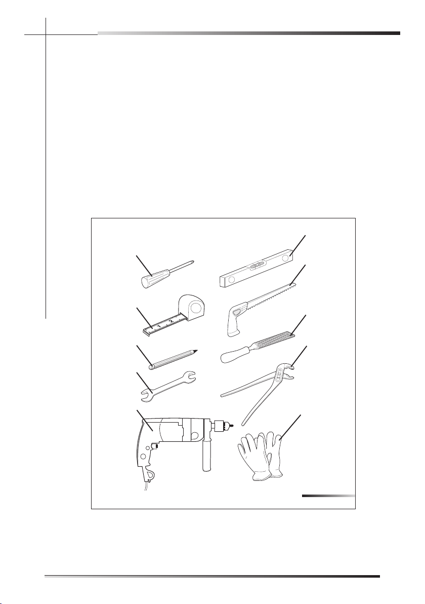
3 INSTALLATION MATERIAL
:der i uqer era s l a i retam gniwol lof eht , y l tcer roc rehsawhs id eht l l atsni oT
; )10-3 .g fi A . fer ( rev i rdwercs spi l l ihP •
• spirit level (ref. B fi g. 3-01);
• tape measure (ref. C fi g. 3-01);
• compass saw (ref. D fi g. 3-01);
• pencil (ref. E fi g. 3-01);
• fi le (ref. F fi g. 3-01);
• 13 mm open-ended wrench (ref. G fi g. 3-01);
• plumbing pliers (ref. H fi g. 3-01);
• drill (ref. I fi g. 3-01);
• safety gloves (ref. L fi g. 3-01).
Fig. 3-01
A
B
C
D
E
F
G
H
I
L
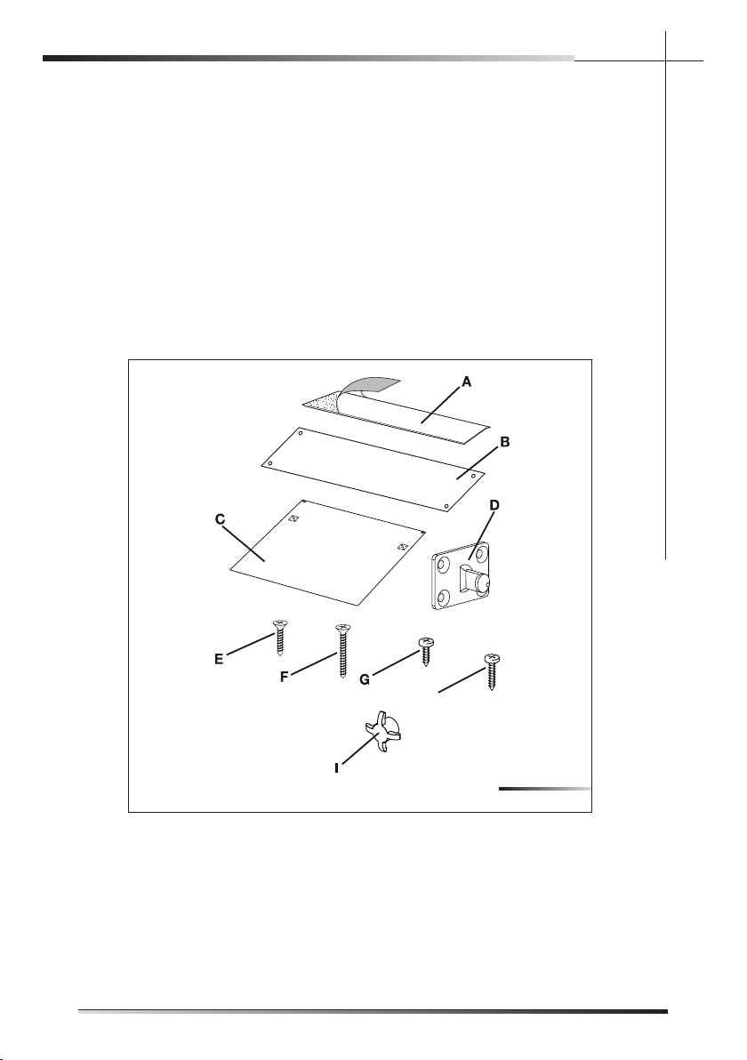
3.1 Kit supplied with dishwasher
The kit supplied with the dishwasher comprises:
• 1 adhesive steam guard (depending on the model) (ref. A fig. 3-02);
• 1 steel adhesive steam guard (depending on the model) (ref. B fig. 3-02)*;
• 1 template for door panel (ref. C fig. 3-02);
• 2 hooks for door panel (ref. D fig. 3-02);
• 8 screws for securing the door panel hooks (ref. E fig. 3-02);
• 2 screws for securing the door (ref. F fig. 3-02);
• 4 screws for fixing the dishwasher to the adjacent walls (ref. G fig. 3-02);
• 2 upper fixing screws (ref. H fig. 3-02);
• 2 screw caps (ref. I Fig. 3-02);
H
* The adhesive protection is suitable for kitchens with worktops that do not allow the
steel protection to be fixed with screws (e.g.:+ marble or masonry), but it can be also
used with other materials.
Fig. 3-02
EN
8
INSTALLATION INSTRUCTION
3 INSTALLATION MATERIAL
:der i uqereras l ai retam gn iwo l lofeht, y l tcer rocrehsawhs idehtl l atsn i oT
; )10-3 .gfiA. fer (rev i rdwercsspi l l ihP•
• spirit level (ref. B fig. 3-01);
• tape measure (ref. C fig. 3-01);
• compass saw (ref. D fig. 3-01);
• pencil (ref. E fig. 3-01);
• file (ref. F fig. 3-01);
• 13 mm open-ended wrench (ref. G fig. 3-01);
• plumbing pliers (ref. H fig. 3-01);
• drill (ref. I fig. 3-01);
• safety gloves (ref. L fig. 3-01).
Fig. 3-01
A
B
C
D
E
F
G
H
I
L
3.1 Kit supplied with dishwasher
The kit supplied with the dishwasher comprises:
• 1 adhesive steam guard (depending on the model) (ref. A fig. 3-02);
• 1 steel adhesive steam guard (depending on the model) (ref. B fig. 3-02)*;
• 1 template for door panel (ref. C fig. 3-02);
• 2 hooks for door panel (ref. D fig. 3-02);
• 8 screws for securing the door panel hooks (ref. E fig. 3-02);
• 2 screws for securing the door (ref. F fig. 3-02);
• 4 screws for fixing the dishwasher to the adjacent walls (ref. G fig. 3-02);
• 2 upper fixing screws (ref. H fig. 3-02);
• 2 screw caps (ref. I Fig. 3-02);
H
* The adhesive protection is suitable for kitchens with worktops that do not allow the
steel protection to be fixed with screws (e.g.:+ marble or masonry), but it can be also
used with other materials.
Fig. 3-02
3.1 Kit supplied with dishwasher
The kit supplied with the dishwasher comprises:
• 1 adhesive steam guard (depending on the model) (ref. A fi g. 3-02);
• 1 steel steam guard (depending on the model) (ref. B fi g. 3-02)*;
• 1 template for door panel (ref. C fi g. 3-02);
• 2 hooks for door panel (ref. D fi g. 3-02);
• 8 screws for securing the door panel hooks (ref. E fi g. 3-02);
• 2 screws for securing the door (ref. F fi g. 3-02);
• 4 screws for fi xing the dishwasher to the adjacent walls (ref. G fi g. 3-02);
• 2 upper fi xing screws (ref. H fi g. 3-02);
• 2 screw caps (ref. I Fig. 3-02);
H
* The adhesive protection is suitable for kitchens with worktops that do not allow the
steel protection to be fi xed with screws (e.g.:+ marble or masonry), but it can be also
used with other materials.
Fig. 3-02
EN
9
INSTALLATION INSTRUCTION
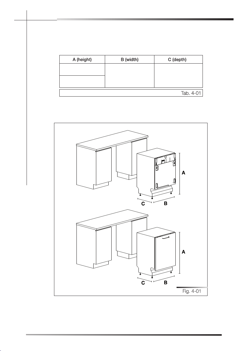
4 DIMENSIONS OF DISHWASHER
(See fi g. 4-01)
A
B
C
Fig. 4-01
A (height) B (width) C (depth)
82 cm - 89 cm
32-9/32” - 35-3/64”
59.7 cm ÷ 59,9 cm
23-1/2” ÷ 23-37/64”
55 cm
21-21/32”
Tab. 4-01
*STX
55 cm - 21-21/32"
60 cm - 23-5/8" *
*STX models
A: according to the models
C: 23-5/8" only for STX models
86 cm ¸ 93 cm
33-35/64"¸36-39/64"
82 cm ¸ 89 cm
32-9/32" ¸ 35-3/64"
59,7 cm ¸ 59,9 cm
23-1/2" ¸ 23-37/64"
INGLESE
EN
10
INSTALLATION INSTRUCTION
4 DIMENSIONS OF DISHWASHER
(See fig. 4-01)
A
B
C
Fig. 4-01
A (height) B (width) C (depth)
82 cm - 89 cm
32-9/32” - 35-3/64”
59.7 cm ÷ 59,9 cm
23-1/2” ÷ 23-37/64”
55 cm
21-21/32”
Tab. 4-01
4 DIMENSIONS OF DISHWASHER
(See fig. 4-01)
Model A (height) B (width) C (depth)
ST8644U
ST8646U
82 cm - 89 cm
32-9/32” - 35-3/64”
59.7 cm ÷ 59,9 cm
23-1/2” ÷ 23-37/64”
55 cm
21-21/32”
ST8644XU
ST8646XU
82 cm - 89 cm
32-9/32” - 35-3/64”
59.7 cm ÷ 59.9 cm
23-1/2” ÷ 23-37/64”
60 cm
23-5/8”
Tab. 4-01
A
B
C
Fig. 4-01
PU- KOOH DNA NO I TALLATSN I 5
F L E S RUO Y E RU J N I O T T ON E R AC E K A T , NO I T A L L A T SN I GN I RUD
ON THE SHARP EDGES OF THE APPLIANCE.
- n i nesohc eh t n i ecna i l ppa eh t no i t i soP . skco l b kca r ene r y t s y l op eh t evomeR
stallation position. The sides and rear of the appliance can lie against kitchen
units or walls. If the dishwasher is installed next to a heat source, separate it
with a heat insulating panel in order to prevent overheating and malfunctions.
To assure stability, only install built-in appliances under continuous worktops,
. swe r cs h t i w po t k r ow r o s t i nu nehc t i k t neca j da eh t o t meh t gn i r uces
S I BOH C I MAREC A HT AENREDNU REHSAWHS I D A N I - GN I DL I UB
ABSOLUTELY FORBIDDEN. A DISHWASHER CAN BE BUILT-IN
UNDERNEATH A CONVENTIONAL HOB PROVIDED THERE IS NO
BREAK IN THE KITCHEN WORKTOP, AND THE DISHWASHER
AND HOB ARE INSTALLED AND SECURED CORRECTLY, SO
THAT NO HAZARDS ARE GENERATED.
MAKE SURE THE DISHWASHER HAS BEEN CORRECTLY IN-
STALLED AND GROUNDED BY A QUALIFIED FITTER. THIS
SAFETY REQUIREMENT MUST BE MET. IN CASE OF DOUBT,
CALL IN A QUALIFIED FITTER. THE MANUFACTURER DE-
CLINES ALL RESPONSIBILITY FOR DAMAGE TO PERSONS
OR PROPERTY RESULTING FROM THE FAILURE TO GROUND
THE APPLIANCE OR FROM A DEFECTIVE GROUND CON-
NECTION .
BEFORE PROCEEDING WITH INSTALLATION, DISCONNECT
THE MAINS POWER SUPPLY FROM THE WORK AREA.
Only for free-standing models
. rehsawhsid gnidnats-eer f a revo boh a tnuom ot neddibrof y l tci r ts si t I •
EN
11
INSTALLATION INSTRUCTION
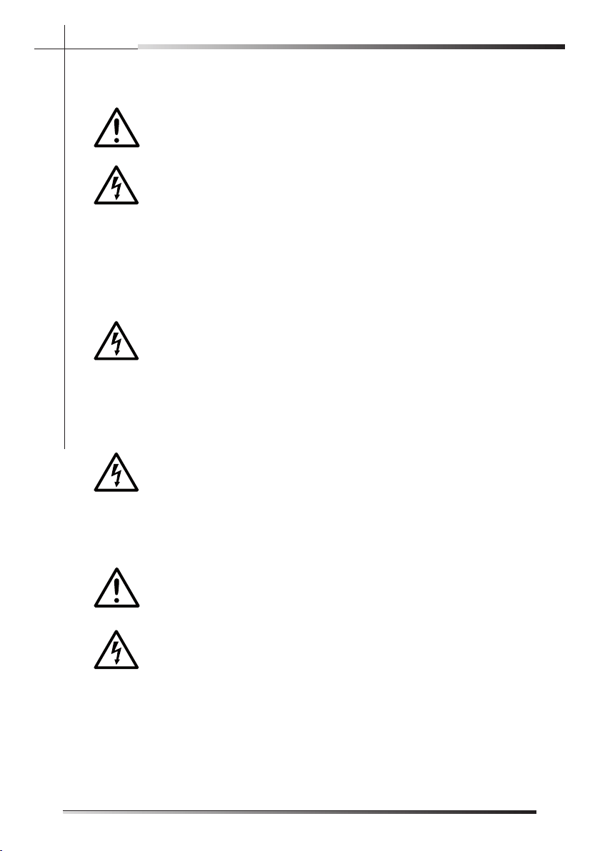
• If the appliance is not in a niche and can therefore be accessed on one
side, cover the door hinge area for safety reasons (cutting hazard). Covers
are available as accessories from specialized retailers or from the Technical
Service Centre.
•To build in the dishwasher, purchase the relative kit from specialized retail-
ers or from the Technical Service Centre.
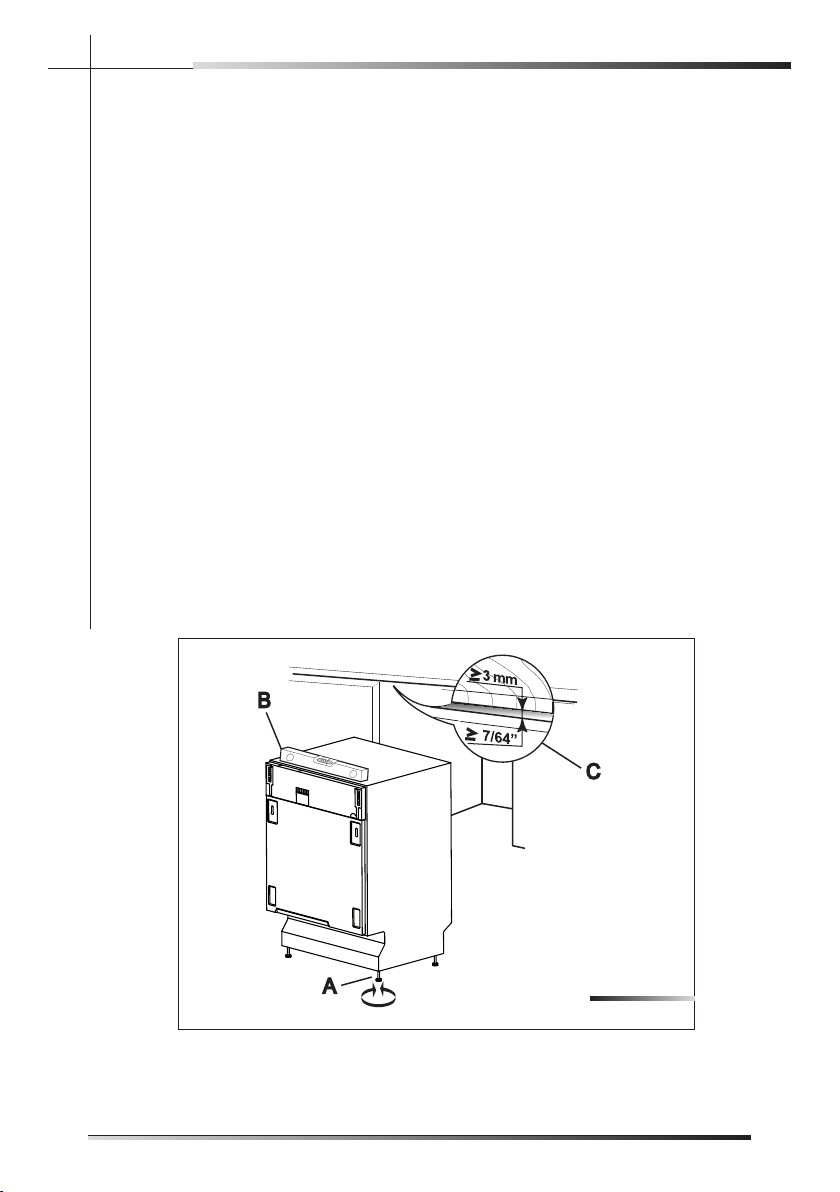
5.1 Leveling
5.1.2 Levelling the appliance
Level the appliance using the relative adjustable feet (e.g.: ref. A fi g. 5-01); use
an open-ended wrench to rotate the feet until the dishwasher is perfectly level.
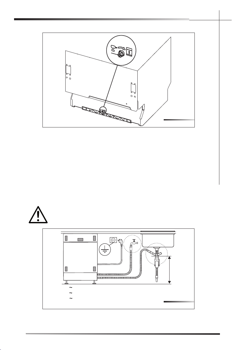
Some models are fi tted with just one rear foot which can be adjusted with a
screw located at the bottom front of the appliance (ref. A fi g. 5-02); use a suit-
able Phillips screwdriver or 8 mm hex head bushing to turn the screw until the
dishwasher is perfectly level.
Use a spirit level to check the appliance is perfectly level (ref. B fi g. 5-01).
Leveling is vital for assuring correct dishwasher operation.
Make sure to leave a gap of at least 3 mm (7/64”) between the top of the dish-
washer and the worktop (ref. C fi g. 5-01).
Fig. 5-01
EN
12
INSTALLATION INSTRUCTION
• If the appliance is not in a niche and can therefore be accessed on one
side, cover the door hinge area for safety reasons (cutting hazard). Covers
are available as accessories from specialized retailers or from the Technical
Service Centre.
•To build in the dishwasher, purchase the relative kit from specialized retail-
ers or from the Technical Service Centre.
5.1 Leveling
5.1.2 Levelling the appliance
Level the appliance using the relative adjustable feet (e.g.: ref. A fig. 5-01); use
an open-ended wrench to rotate the feet until the dishwasher is perfectly level.
Some models are fitted with just one rear foot which can be adjusted with a
screw located at the bottom front of the appliance (ref. A fig. 5-02); use a suit-
able Phillips screwdriver or 8 mm hex head bushing to turn the screw until the
dishwasher is perfectly level.
Use a spirit level to check the appliance is perfectly level (ref. B fig. 5-01).
Leveling is vital for assuring correct dishwasher operation.
Make sure to leave a gap of at least 3 mm (7/64”) between the top of the dish-
washer and the worktop (ref. C fig. 5-01).
Fig. 5-01
• If the appliance is not in a niche and can therefore be accessed on one
side, cover the door hinge area for safety reasons (cutting hazard). Covers
are available as accessories from specialized retailers or from the Technical
Service Centre.
• To build in the dishwasher, purchase the relative kit from specialized retail-
ers or from the Technical Service Centre.
5.1 Leveling
5.1.2 Levelling the appliance
Level the appliance using the relative adjustable feet (e.g.: ref. A fig. 5-01); use
an open-ended wrench to rotate the feet until the dishwasher is perfectly level.
Some models are fitted with just one rear foot which can be adjusted with a
screw located at the bottom front of the appliance (ref. A fig. 5-02); use a suit-
able Phillips screwdriver or 8 mm hex head bushing to turn the screw until the
dishwasher is perfectly level.
Use a spirit level to check the appliance is perfectly level (ref. B fig. 5-01).
Leveling is vital for assuring correct dishwasher operation.
Make sure to leave a gap of at least 3 mm (7/64”) between the top of the dish-
washer and the worktop (ref. C fig. 5-01).
Fig. 5-01
Fig. 5-02
5.2 Connections
- yh dna l ac i r t ce l e eh t o t ssecca f o esae wo l l a o t sa os r ehsawhs i d eh t l l a t sn I
draulic connections through the adjacent unit. These connections must never
be behind the dishwasher.
The inlet and drain hoses can be pointed in all directions. make sure that they
are not bent, crushed or too tight. Tighten the ring nut after pointing the hoses
in the required direction.
Figure 5-03 indicates the distances to maintain between the dishwasher and
the various connections.
! DRAZAH ER I F
DO NOT COVER OR CRUSH THE CORD PLUG.
A = 1200 mm / 47”
B = 1500 mm / 59”
C = 1600 mm / 63”
D = min. 400 mm / 16”
A
B
D
C
Fig. 5-03
EN
13
INSTALLATION INSTRUCTION
eh t ssap o t de r i uqe r s i ) ” 23 / 5 ( mc 8 t sae l t a f o r e t ema i d a h t i w e l oh hguo r h t A
hoses and power cord (ref. A fi g. 5-04).
Make sure there area no rough edges that could damage the power cord or
hoses. If the dishwasher is installed in a metal unit protect the edge of the
through hole for the hoses and power cord with a gasket. Do not use extension
cords when making the electrical connection as these do not guarantee safety.
ATTENTION!
INSTALLING THE DISHWASHER IN A NARROW SPACE MAY BEND
OR CRUSH THE POWER CORD. TAKE GREAT CARE IN ORDER TO
REDUCE THE POSSIBILITY OF DAMAGING THE POWER CORD
WHEN INSTALLING OR REMOVING THE APPLIANCE.
A
y l ppus r e t aw eh t o t gn i t cennoC 1 . 2 . 5
PREVENTING THE RISK OF CLOGGING OR DAMAGE: IF THE
WATER PIPE IS NEW OR HAS NOT BEEN USED FOR A LONG
TIME, BEFORE CONNECTING TO THE WATER SUPPLY CHECK
THAT THE WATER IS CLEAR AND FREE OF IMPURITIES, TO PRE-
VENT DAMAGE TO THE APPLIANCE. THE DISHWASHER MUST
ALWAYS BE CONNECTED TO THE WATER SYSTEM WITH
NEW HOSES; OLD OR USED HOSES MUST NEVER BE RE-
USED.
Fig. 5-04
EN
14
INSTALLATION INSTRUCTION
eh ts sapo tde r i uqe rs i ) ” 23 / 5 (mc8t sae l t af or e t ema i dah t i we l ohhguo r h tA
hoses and power cord (ref. A fig. 5-04).
Make sure there area no rough edges that could damage the power cord or
hoses. If the dishwasher is installed in a metal unit protect the edge of the
through hole for the hoses and power cord with a gasket. Do not use extension
cords when making the electrical connection as these do not guarantee safety.
ATTENTION!
INSTALLING THE DISHWASHER IN A NARROW SPACE MAY BEND
OR CRUSH THE POWER CORD. TAKE GREAT CARE IN ORDER TO
REDUCE THE POSSIBILITY OF DAMAGING THE POWER CORD
WHEN INSTALLING OR REMOVING THE APPLIANCE.
A
y l ppusr e t aweh to t gn i t cennoC1 . 2 . 5
PREVENTING THE RISK OF CLOGGING OR DAMAGE: IF THE
WATER PIPE IS NEW OR HAS NOT BEEN USED FOR A LONG
TIME, BEFORE CONNECTING TO THE WATER SUPPLY CHECK
THAT THE WATER IS CLEAR AND FREE OF IMPURITIES, TO PRE-
VENT DAMAGE TO THE APPLIANCE. THE DISHWASHER MUST
ALWAYS BE CONNECTED TO THE WATER SYSTEM WITH
NEW HOSES; OLD OR USED HOSES MUST NEVER BE RE-
USED.
Fig. 5-04
eh ts sapo tde r i uqe rs i ) ” 23 / 5 (mc8t sae l t af or e t ema i dah t i we l ohhguo r h tA
hoses and power cord (ref. A fig. 5-04).
Make sure there area no rough edges that could damage the power cord or
hoses. If the dishwasher is installed in a metal unit protect the edge of the
through hole for the hoses and power cord with a gasket. Do not use extension
cords when making the electrical connection as these do not guarantee safety.
ATTENTION!
INSTALLING THE DISHWASHER IN A NARROW SPACE MAY BEND
OR CRUSH THE POWER CORD. TAKE GREAT CARE IN ORDER TO
REDUCE THE POSSIBILITY OF DAMAGING THE POWER CORD
WHEN INSTALLING OR REMOVING THE APPLIANCE.
A
y l ppusr e t aweh to tgn i t cennoC1 . 2 . 5
PREVENTING THE RISK OF CLOGGING OR DAMAGE: IF THE
WATER PIPE IS NEW OR HAS NOT BEEN USED FOR A LONG
TIME, BEFORE CONNECTING TO THE WATER SUPPLY CHECK
THAT THE WATER IS CLEAR AND FREE OF IMPURITIES, TO PRE-
VENT DAMAGE TO THE APPLIANCE. THE DISHWASHER MUST
ALWAYS BE CONNECTED TO THE WATER SYSTEM WITH
NEW HOSES; OLD OR USED HOSES MUST NEVER BE RE-
USED.
Fig. 5-04
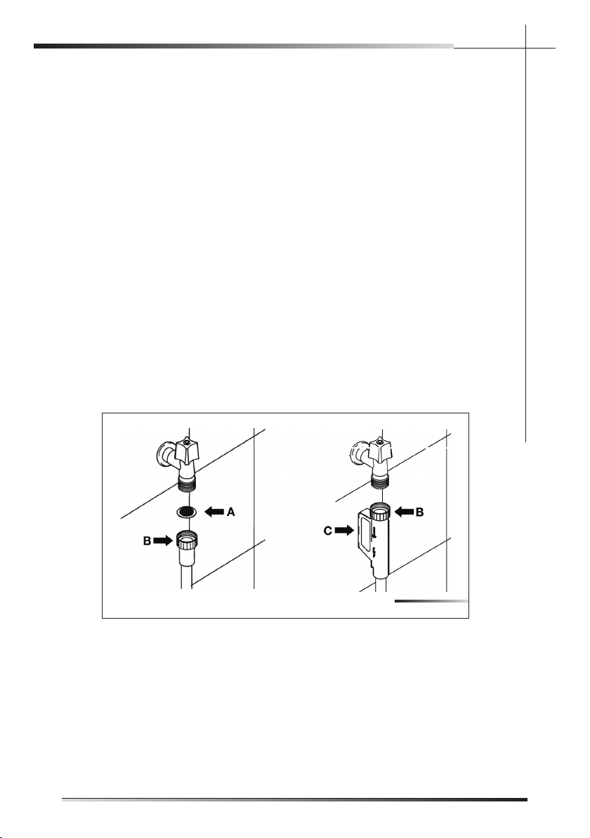
5.2.1.1 Connecting to the water tap
de i l ppus eh t gn i t t fi , pa t r e t aw d l oc sag ”¾ dedae r h t a o t esoh t e l n i eh t t cennoC
fi lter (ref. A fi g. 5-05). Firmly secure the hose by tightening the relative
ring nut with your hands (ref. B fi g. 5-05); fi nish by tightening another
¼ turn using a pair of plumbing pliers. For models fi tted with ACQUAS-
TOP (ref. C fi g. 5-05) the fi lter is already present in the threaded ring nut.
The dishwasher can be fi lled with water at a temperature of less than
60°C (140°F).
If the appliance is fi lled with hot water, washing times will be reduced by about
20 minutes, but effi ciency will be slightly impaired. Make the connection to the
domestic hot water tap using the same methods described for connecting the
appliance to the cold water tap.
• Recommended temperature: 49°C (120°F), max. 60°C (140°F).
• Recommended water pressure: 0.5 - 9 bar (7 -130 PSI).
. recuder erusserp a t fi ,hg i h oot s i erusserp eht f I
A rubber hose connected to a sink spray may burst if installed on the
same pipes feeding the dishwasher. If your sink is fi tted with this ac-
cessory, remove the hose and plug the hole.
Fig. 5-05
EN
15
INSTALLATION INSTRUCTION
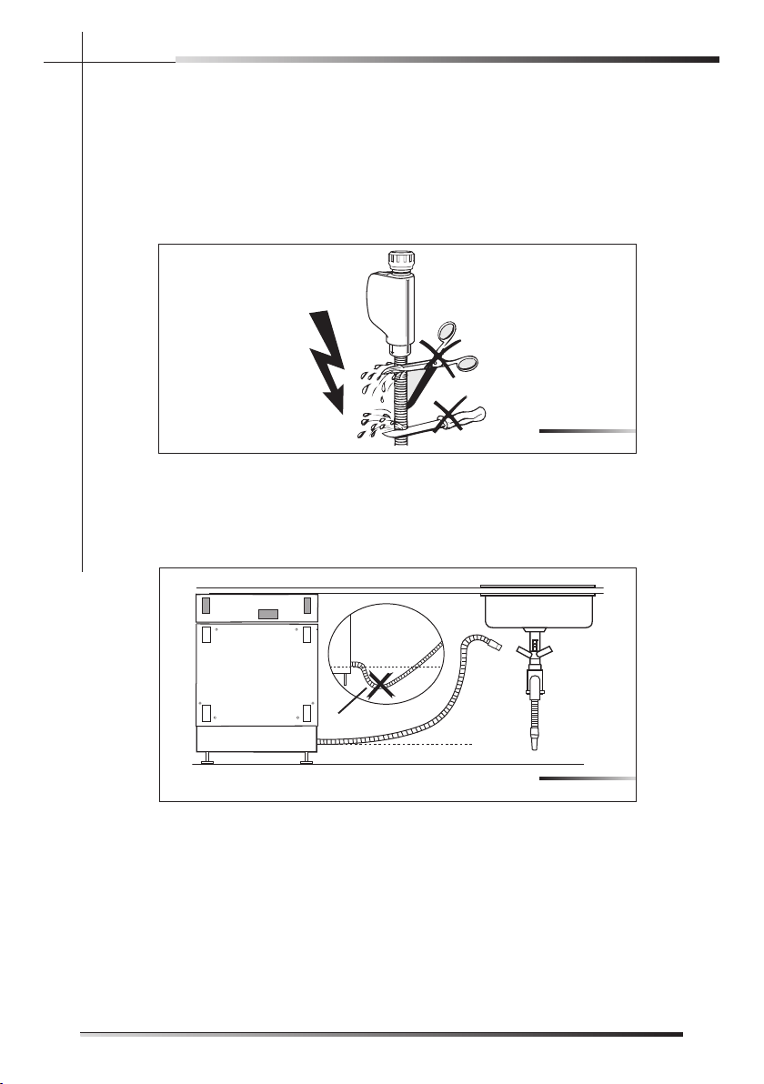
Do not cut the inlet hose (see fi g. 5-06).
If the hose is cut, the dishwasher will not work, water will leak and you may be
injured.
If the hose is too long, wind it up tidily and place it behind the appliance.
The cable harness and electrical components must not come into contact with
the hydraulic system and the water inlet and drain hoses.
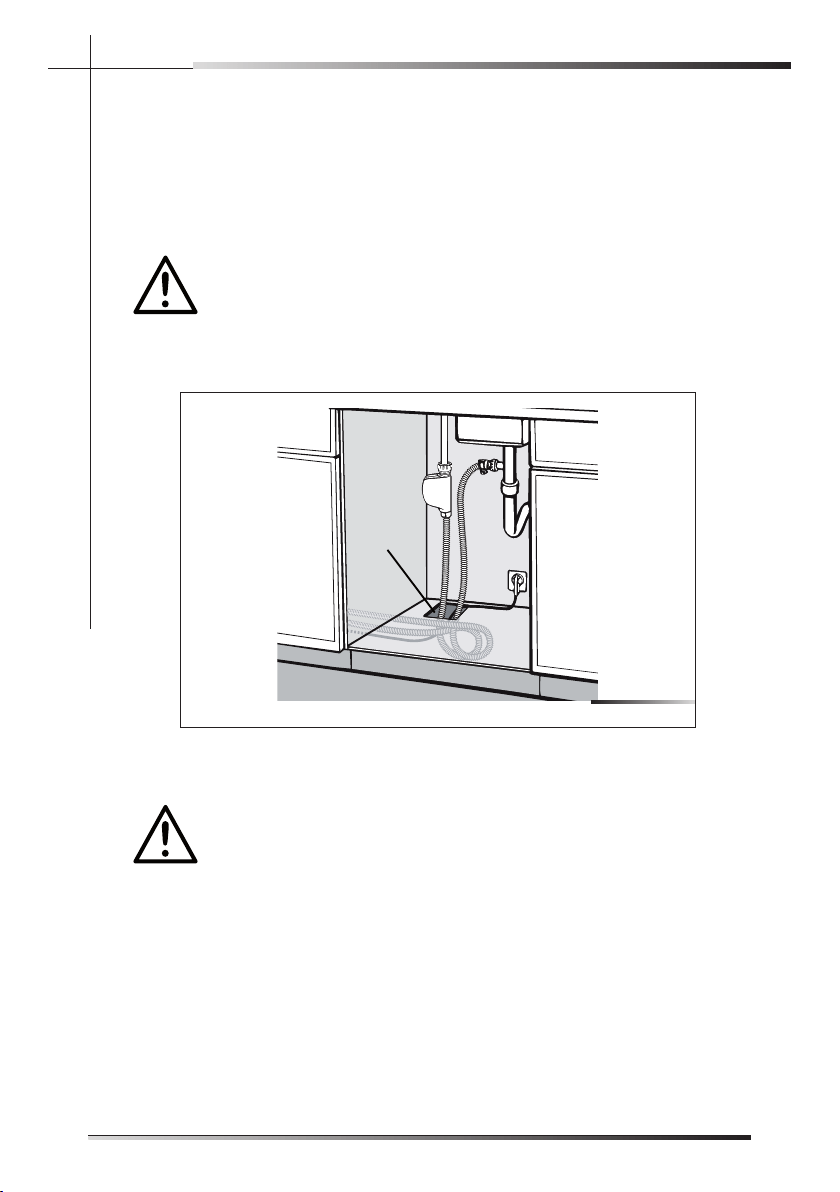
When connecting the dishwasher drain hose to the sink make sure that the
hose is not bent (ref. A fi g. 5-07) in order to prevent cracks or breakages that
could damage it.
Fig. 5-07
A
Fig. 5-06
EN
16
INSTALLATION INSTRUCTION
Do not cut the inlet hose (see fig. 5-06).
If the hose is cut, the dishwasher will not work, water will leak and you may be
injured.
If the hose is too long, wind it up tidily and place it behind the appliance.
The cable harness and electrical components must not come into contact with
the hydraulic system and the water inlet and drain hoses.
When connecting the dishwasher drain hose to the sink make sure that the
hose is not bent (ref. A fig. 5-07) in order to prevent cracks or breakages that
could damage it.
Fig. 5-07
A
Fig. 5-06
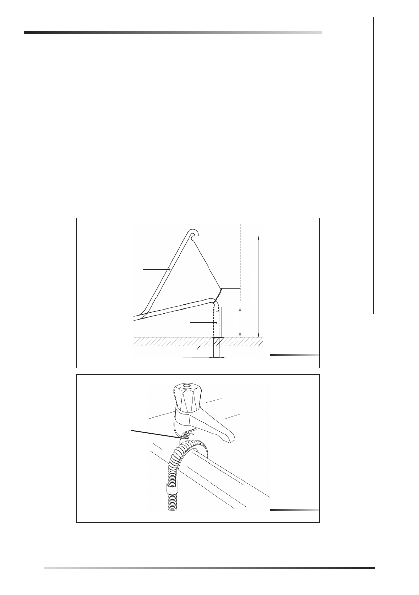
esoh niard eht gni tcennoC2.1.2
n i a r d a o t gn i t cennoC
Insert the relative hose into a drain with a minimum diameter of 4 cm (1-37/64”)
(ref. A fi g. 5-08); alternatively, place the hose on the sink (ref. B fi g. 5-08) using
the supplied hose support (see fi g. 5-9), but taking care to avoid obstructions
or excessive curving. Make sure the hose cannot fall out. For this purpose,
the hose support is fi tted with a hole (ref. A fi g. 5-9) which can be used to fi x
it to the wall or the tap with a piece of string. The free end must lie at a height
ranging from of 30 to 100 cm (from of 1-7/32” to 3-59/64”) (see fi g. 5-08)
and must never be immerged in water. If horizontal extension hoses with a
maximum length of 3m are used, position the drain hose at a maximum height
of 85 cm (3-11/32”) above the fl oor.
Fig. 5-08
A
B
min O4 cm
1-37/64”
min 30 cm
1-7/32”
MAX 100 cm
3-59/64”
Fig. 5-9
A
5.
EN
17
INSTALLATION INSTRUCTION
Connecting to a “T” union of the drain circuit
MAKE THE CONNECTION UPLINE FROM THE SIPHON OF THE
DRAIN LINE AND AT LEAST 400 mm (15-3/4”) ABOVE THE FLOOR
ON WHICH THE DISHWASHER WILL BE INSTALLED.
1.
Connect the dishwasher drain hose (ref. A fi g. 5-10) to the “T” union (ref. B
fi g. 5-10) of the drain circuit using a 38 to 50 mm (1-1/2 to 2”) screw clamp*
(ref. C fi g. 5-10); if necessary, cut the end of the dishwasher drain hose (ref.
D fi g. 5-10) (do not cut the corrugated section).
* Available from any plumbing stockist
Fig. 5-10
A
C
B
D
EN
18
INSTALLATION INSTRUCTION
Connecting to a “T” union of the drain circuit
MAKE THE CONNECTION UPLINE FROM THE SIPHON OF THE
DRAIN LINE AND AT LEAST 400 mm (15-3/4”) ABOVE THE FLOOR
ON WHICH THE DISHWASHER WILL BE INSTALLED.
1.
Connect the dishwasher drain hose (ref. A fig. 5-10) to the “T” union (ref. B
fi g. 5-10) of the drain circuit using a 38 to 50 mm (1-1/2 to 2”) screw clamp*
(ref. C fig. 5-10); if necessary, cut the end of the dishwasher drain hose (ref.
D fig. 5-10) (do not cut the corrugated section).
* Available from any plumbing stockist
Fig. 5-10
A
C
B
D
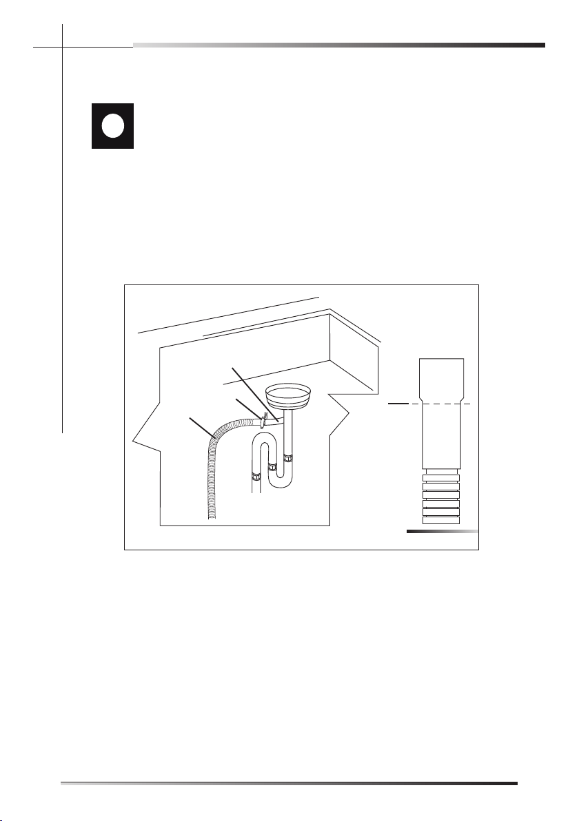
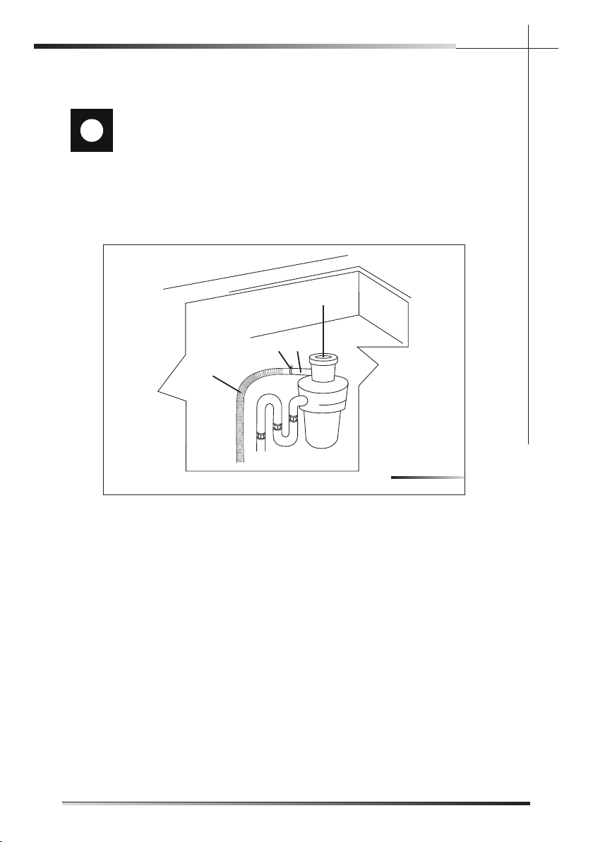
Connecting to a waste disposal unit with an air gap
MAKE THE CONNECTION UPLINE FROM THE SIPHON OF THE
DRAIN LINE AND AT LEAST 400 mm (15-3/4”) ABOVE THE FLOOR
ON WHICH THE DISHWASHER WILL BE INSTALLED.
1.
Remove the cover of the waste disposal unit (ref. A fi g. 5-11).
2.
Connect the dishwasher drain hose (ref. B fi g. 5-11) to the air gap (ref. C
fi g. 5-11) using the wide spring clamp (ref. D fi g. 5-11); if necessary, cut the
end of the dishwasher drain hose (ref. E fi g. 5-12) (do not cut the corrugated
section). If the drain hose has been cut, use a 38 to 50 mm (1-1/2 to 2”)
screw clamp*.
3. To connect the air gap (ref. C fi g. 5-11) to the waste disposal unit inlet (ref. F
fi g. 5-11), use a rubber union* (ref. G fi g. 5-11) with spring or screw clamps*
(ref. H fi g. 5-11).
* Available from any plumbing stockist
Fig. 5-11
C
D
B
G
H
H
A
E
EN
19
INSTALLATION INSTRUCTION
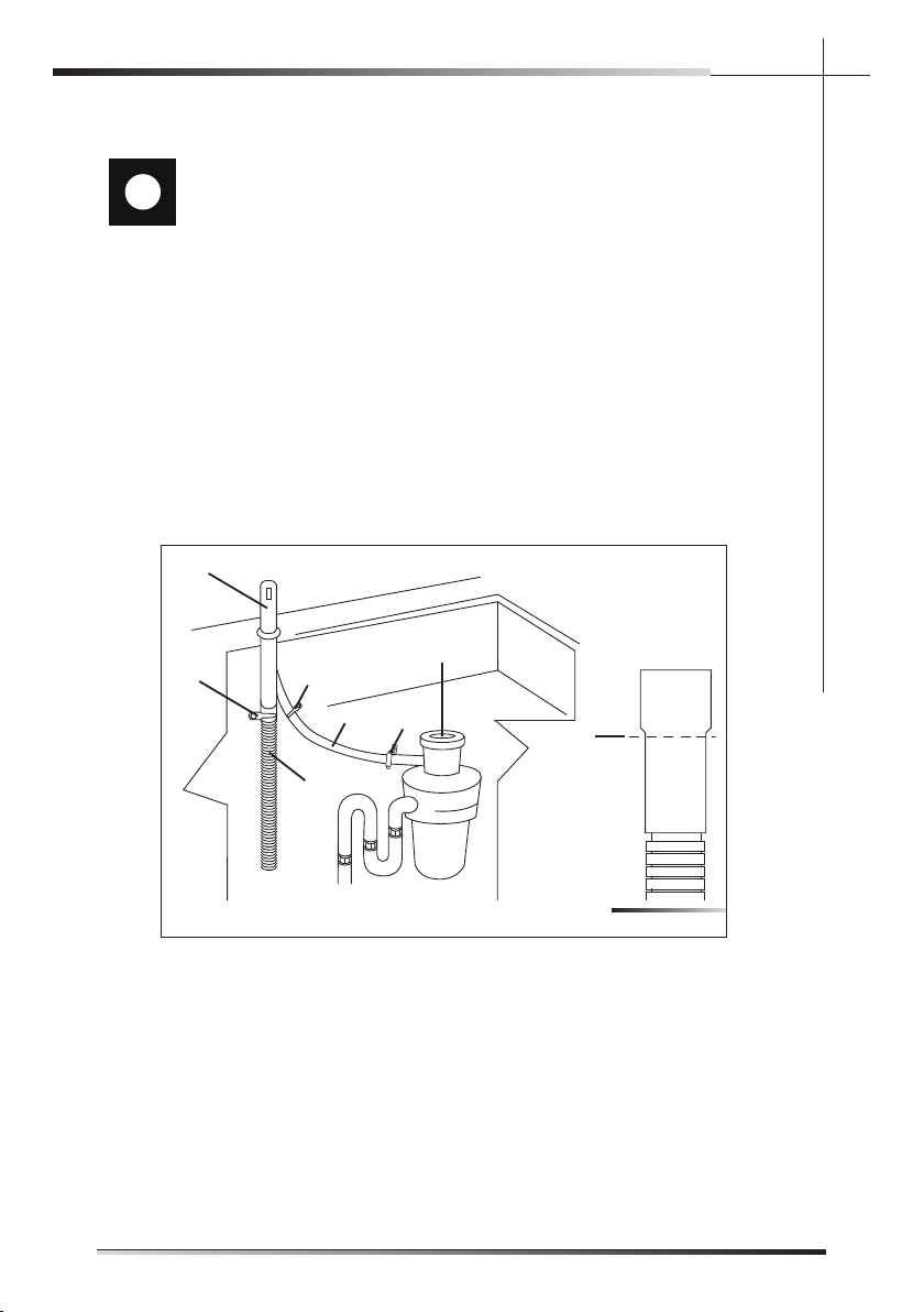
Connecting to the air gap (no waste disposal unit)
MAKE THE CONNECTION UPLINE FROM THE SIPHON OF THE
DRAIN LINE AND AT LEAST 400 mm (15-3/4”) ABOVE THE FLOOR
ON WHICH THE DISHWASHER WILL BE INSTALLED.
1.
Connect the dishwasher drain hose (ref. A fi g. 5-12) to the air gap (ref. B fi g.
5-12) using the wide spring clamp (ref. C fi g. 5-12); if necessary, cut the end
of the dishwasher drain hose (ref. D fi g. 5-12) (do not cut the corrugated
section). If the drain hose has been cut, use a 38 to 50 mm (1-1/2 to 2”)
screw clamp*.
2.
To connect the air gap (ref. B fi g. 5-12) to the “T” union (ref. E fi g. 5-12) of the
drain line, use a rubber union* (ref. F fi g. 5-12) with spring or screw clamps*
(ref. G fi g. 5-12).
* Available from any plumbing stockist
Fig. 5-12
B
C
A
F
G
G
D
E
EN
20
INSTALLATION INSTRUCTION
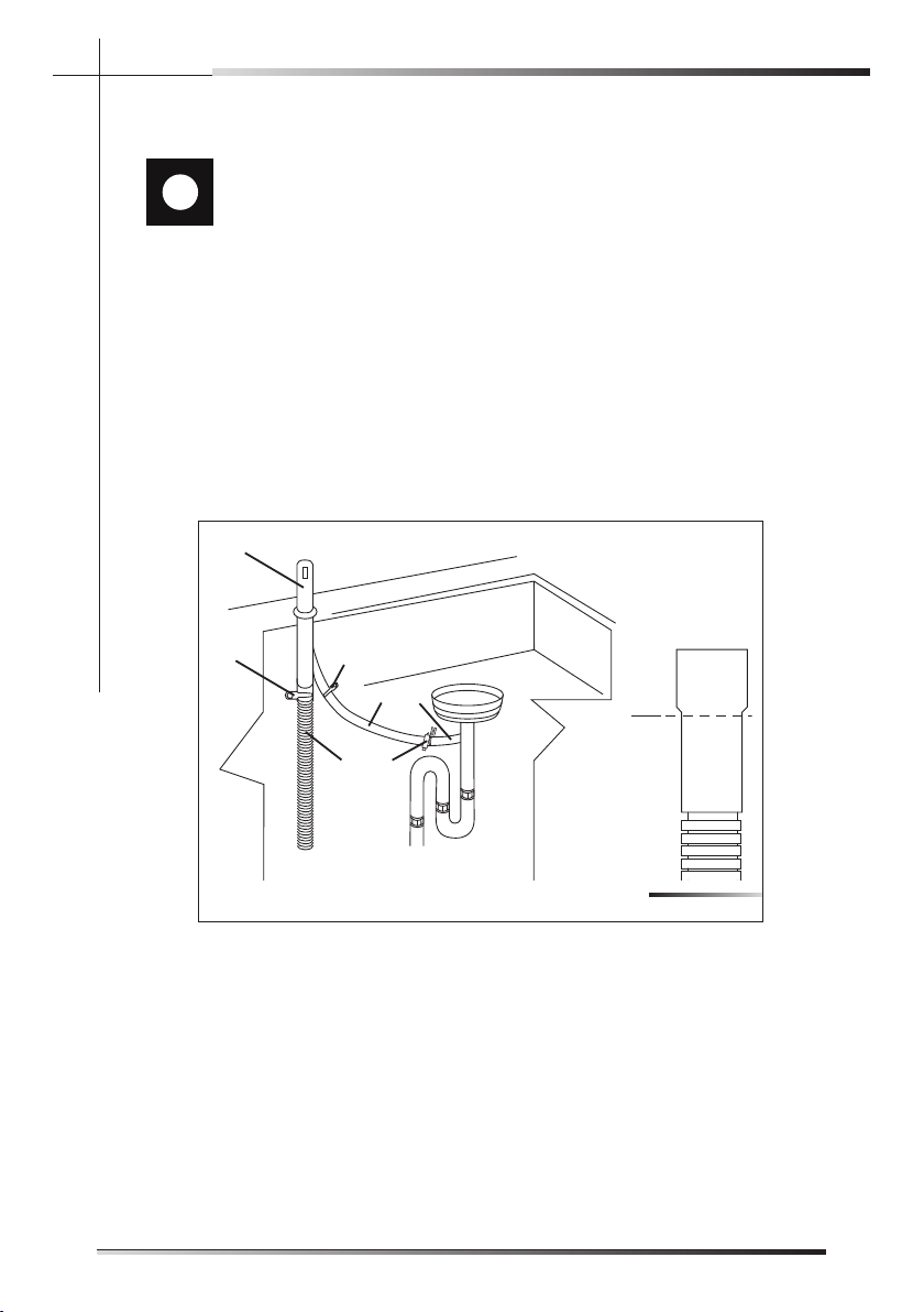
Connecting to the air gap (no waste disposal unit)
MAKE THE CONNECTION UPLINE FROM THE SIPHON OF THE
DRAIN LINE AND AT LEAST 400 mm (15-3/4”) ABOVE THE FLOOR
ON WHICH THE DISHWASHER WILL BE INSTALLED.
1.
Connect the dishwasher drain hose (ref. A fig. 5-12) to the air gap (ref. B fig.
5-12) using the wide spring clamp (ref. C fig. 5-12); if necessary, cut the end
of the dishwasher drain hose (ref. D fig. 5-12) (do not cut the corrugated
section). If the drain hose has been cut, use a 38 to 50 mm (1-1/2 to 2”)
screw clamp*.
2.
To connect the air gap (ref. B fig. 5-12) to the “T” union (ref. E fig. 5-12) of the
drain line, use a rubber union* (ref. F fig. 5-12) with spring or screw clamps*
(ref. G fig. 5-12).
* Available from any plumbing stockist
Fig. 5-12
B
C
A
F
G
G
D
E
Connecting to a waste disposal unit (no air gap)
MAKE THE CONNECTION UPLINE FROM THE SIPHON OF THE
DRAIN LINE AND AT LEAST 400 mm (15-3/4”) ABOVE THE FLOOR
ON WHICH THE DISHWASHER WILL BE INSTALLED.
1.
Remove the cover of the waste disposal unit (ref. A fi g. 5-13).
2.
Connect the dishwasher drain hose (ref. B fi g. 5-13) to the waste disposal
unit inlet (ref. C fi g. 5-13), using the wide spring clamp (ref. D fi g. 5-13).
Fig. 5-13
B
D
C
A
EN
21
INSTALLATION INSTRUCTION
sgn i n r aw dna sno i t cennoc l ac i r t ce l E 2 . 2 . 5
EHT FO YCNEUQERF EHT DNA EGA T LOV EHT T AHT KCEHC
MAINS MATCH THE RATINGS ON THE NAME PLATE OF THE AP-
PLIANCE POSITIONED ON THE INNER EDGE OF THE DOOR.
IN THE EVENT OF DAMAGE TO THE SUPPLY CORD, HAVE
IT REPLACED BY THE MANUFACTURER OR AN AUTHORIZED
TECHNICAL SERVICE CENTRE.
THIS APPLIANCE MUST BE GROUNDED. IN CASE OF A MAL-
FUNCTION OF FAULT, THE GROUND REDUCES THE RISK OF
ELECTROCUTION BY PROVIDING THE ELECTRICAL CURRENT
WITH AN ALTERNATIVE, LESS RESISTANT PATH.
THIS APPLIANCE MUST BE GROUNDED. IN CASE OF A MAL-
FUNCTION OF FAULT, THE GROUND REDUCES THE RISK OF
ELECTROCUTION BY PROVIDING THE ELECTRICAL CURRENT
WITH AN ALTERNATIVE, LESS RESISTANT PATH. THIS APPLI-
ANCE IS FITTED WITH A SUPPLY CORD CONTAINING A GROUND
WIRE AND PLUG. FIT THE PLUG INTO A SUITABLE SOCKET, IN-
STALLED AND GROUNDED IN COMPLIANCE WITH THE LAWS IN
FORCE IN THE COUNTRY OF INSTALLATION.
BEFORE MAKING ELECTRICAL CONNECTIONS, DISCON-
NECT THE MAINS POWER SUPPLY FROM THE WORK AREA.
sno i t cu r t sn i gn i dnuo rG
otn i gu lp eht t i F .gu lp dna er iw dnuorg ht iw droc a ht iw det t fi s
i ecna i l ppa s i hT
a suitable socket, installed and grounded in compliance with the laws in force
in the country of installation.
- L A T SN I FO ECA L P EHT N I Y L PPUS SN I AM EHT T AHT KCEHC
LATION COMPLIES WITH THE REGULATIONS IN FORCE IN THE
COUNTRY OF USE, AND THAT IT IS CORRECTLY GROUNDED.
WARNING AN INCORRECTLY CONNECTED GROUND WIRE MAY
GENERATE THE RISK OF ELECTROCUTION. IF IN DOUBT AS TO
THE CORRECT GROUNDING OF THE APPLIANCE, CALL IN A
QUALIFIED ELECTRICIAN OR THE TECHNICAL ASSISTANCE
SERVICE. DO NOT CHANGE THE PLUG ATTACHED TO THE
APPLIANCE.
EN
22
INSTALLATION INSTRUCTION
sgn i n r aw dnasno i t cennocl ac i r t ce l E 2 . 2 . 5
EHTFO YCNEUQERF EHTDNA EGA T LOV EHTT AHTKCEHC
MAINS MATCH THE RATINGS ON THE NAME PLATE OF THE AP-
PLIANCE POSITIONED ON THE INNER EDGE OF THE DOOR.
IN THE EVENT OF DAMAGE TO THE SUPPLY CORD, HAVE
IT REPLACED BY THE MANUFACTURER OR AN AUTHORIZED
TECHNICAL SERVICE CENTRE.
THIS APPLIANCE MUST BE GROUNDED. IN CASE OF A MAL-
FUNCTION OF FAULT, THE GROUND REDUCES THE RISK OF
ELECTROCUTION BY PROVIDING THE ELECTRICAL CURRENT
WITH AN ALTERNATIVE, LESS RESISTANT PATH.
THIS APPLIANCE MUST BE GROUNDED. IN CASE OF A MAL-
FUNCTION OF FAULT, THE GROUND REDUCES THE RISK OF
ELECTROCUTION BY PROVIDING THE ELECTRICAL CURRENT
WITH AN ALTERNATIVE, LESS RESISTANT PATH. THIS APPLI-
ANCE IS FITTED WITH A SUPPLY CORD CONTAINING A GROUND
WIRE AND PLUG. FIT THE PLUG INTO A SUITABLE SOCKET, IN-
STALLED AND GROUNDED IN COMPLIANCE WITH THE LAWS IN
FORCE IN THE COUNTRY OF INSTALLATION.
BEFORE MAKING ELECTRICAL CONNECTIONS, DISCON-
NECT THE MAINS POWER SUPPLY FROM THE WORK AREA.
sno i t cu r t sn ign i dnuo rG
otn igu lpehtt i F.gu lp dnaer iw dnuorght iw drocaht iw det tfis iecna i l ppas i hT
a suitable socket, installed and grounded in compliance with the laws in force
in the country of installation.
- L A T SN I FO ECA L P EHTN I Y L PPUSSN I AM EHTT AHTKCEHC
LATION COMPLIES WITH THE REGULATIONS IN FORCE IN THE
COUNTRY OF USE, AND THAT IT IS CORRECTLY GROUNDED.
WARNING AN INCORRECTLY CONNECTED GROUND WIRE MAY
GENERATE THE RISK OF ELECTROCUTION. IF IN DOUBT AS TO
THE CORRECT GROUNDING OF THE APPLIANCE, CALL IN A
QUALIFIED ELECTRICIAN OR THE TECHNICAL ASSISTANCE
SERVICE. DO NOT CHANGE THE PLUG ATTACHED TO THE
APPLIANCE.
IF THE PLUG IS NOT SUITABLE FOR THE SOCKET, CALL IN A
QUALIFIED ELECTRICIAN TO FIT A SUITABLE PLUG.
The plug at the end of the power cord and the corresponding socket must be
of the same type and must conform to current regulations governing electrical
appliances. The plug must be accessible after installation. Never remove the
plug by pulling on the wire. If the power cord is damaged, have it replaced
.er tnec eci vres dez i rohtua na ro rerutcafunam eht yb
DO NOT USE EXTENSION CORDS, ADAPTORS OR SHUNT CON-
NECTIONS IN ORDER TO AVOID THE POSSIBILITY OF OVER-
HEATING OR BURNING, WITH CONSEQUENT FIRE HAZARD.
T I E VAH , DROC Y LPPUS EHT OT EGAMAD FO TNEV E EHT N I
RE-
PLACED BY THE MANUFACTURER OR AN AUTHORIZED TECHNI-
CAL SERVICE CENTRE IN ORDER TO AVOID ANY RISK.
gninoissimmoC 3.5
5.3.1 Installation procedure
. g fi ees ( r ood r ehsawhs i d eh t r evo gn i y l po t k r ow eh t f o h t aen r ednu eh t nae l C
5-14) and apply the steam guard, as shown in fi g. 5-15 (see fi g. 5-15 if the
adhesive guard is applied; see fi g. 5-16 if the steel guard is applied). This guard
protects the worktop from steam and condensation when the door of the dish-
washer is opened at the end of the washing cycle.
Fig. 5-14
EN
23
INSTALLATION INSTRUCTION
Push the dishwasher into position, taking care not to twist or crush the power
cord or hoses (see fi g. 5-17).
TWO PEOPLE WEARING SAFETY GLOVES ARE NEEDED TO PUSH
THE DISHWASHER INTO PLACE.
Fig. 5-15
Fig. 5-16
Fig. 5-17
EN
24
INSTALLATION INSTRUCTION
Push the dishwasher into position, taking care not to twist or crush the power
cord or hoses (see fig. 5-17).
TWO PEOPLE WEARING SAFETY GLOVES ARE NEEDED TO PUSH
THE DISHWASHER INTO PLACE.
Fig. 5-15
Fig. 5-16
Fig. 5-17
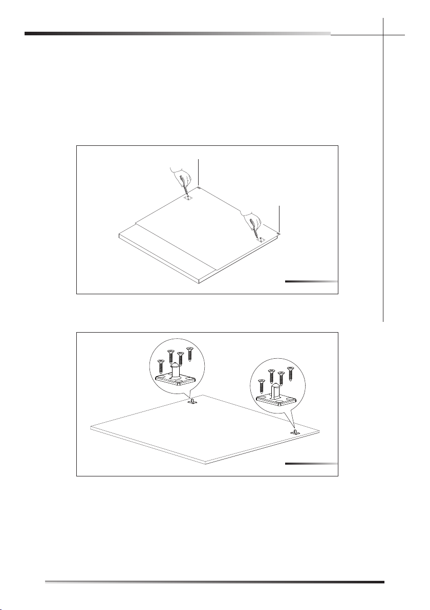
l enapr ood eh tgn i t nuom r o f e r udeco r P2 . 3 . 5
Mount the door panel.
Place the template on the inner surface of the panel, centering it along the up-
per side and matching up the reference locators (ref. A fi g. 5-18); mark the po-
sition of the door hooks with a pencil (see fi g. 5-18). Remove the template
and
use a drill with a suitable bit to make holes at the points mar
ked on the panel.
A
A
Use the screwdriver to secure the door hooks with the 8 supplied screws (see
fi g. 5-19) at the marked reference points.
Fig. 5-18
Fig. 5-19
l enap r ood eh t gn i t nuom r o f e r udeco r P 2 . 3 . 5
Mount the door panel.
Place the template on the inner surface of the panel, centering it along the up-
per side and matching up the reference locators (ref. A fig. 5-18); mark the po-
sition of the door hooks with a pencil (see fig. 5-18). Remove the template and
use a drill with a suitable bit to make holes at the points marked on the panel.
A
A
Use the screwdriver to secure the door hooks with the 8 supplied screws (see
fig. 5-19) at the marked reference points.
Fig. 5-18
Fig. 5-19
(not read for STX models)
EN
25
INSTALLATION INSTRUCTION
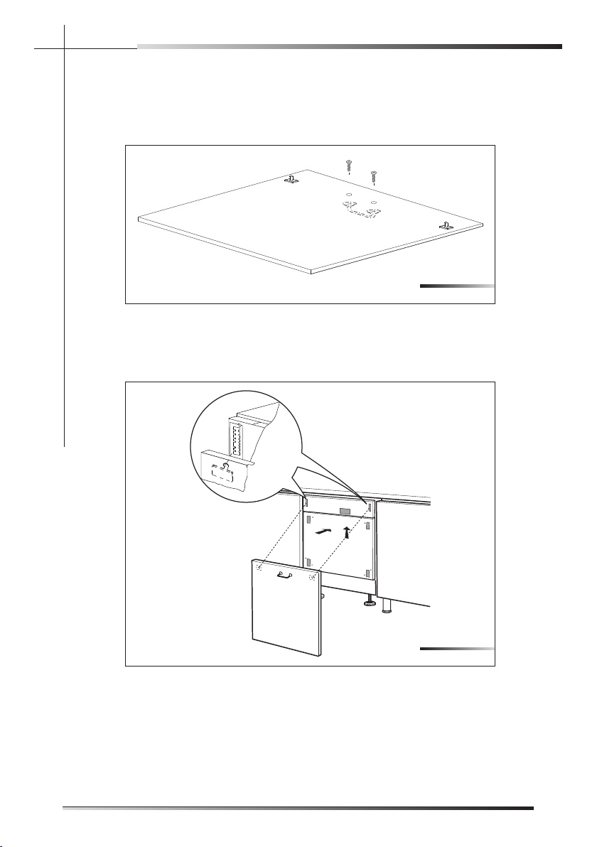
Drill holes for the panel handle using a drill with a suitable bit. Use the screw-
driver to secure the door handle before hooking the panel to the dishwasher
(see fi g. 5-20).
N.B.: the screws are not supplied.
Fastening the door panel: insert the hooks into the respective slots on the
dishwasher and slide the panel upwards (see fi g. 5-21).
1
2
Fig. 5-20
Fig. 5-21
EN
26
INSTALLATION INSTRUCTION
Drill holes for the panel handle using a drill with a suitable bit. Use the screw-
driver to secure the door handle before hooking the panel to the dishwasher
(see fig. 5-20).
N.B.: the screws are not supplied.
Attach the door panel: fit the hooks into their slots on the dishwasher and allow
the panel to slide downwards and slip in to place (see fig. 5-21).
1
2
Fig. 5-20
Fig. 5-21
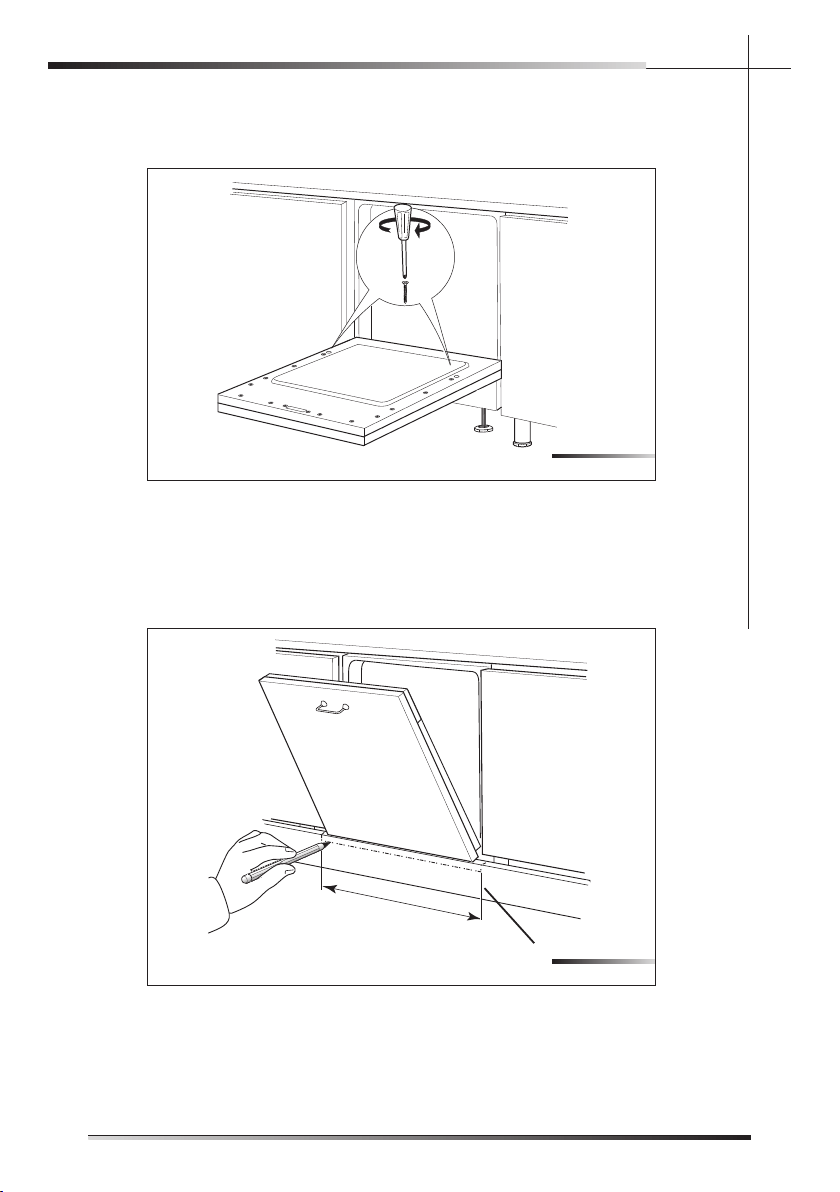
a evah t sum l enap ehT . swe r cs de i l ppus eh t h t i w l enap eh t o t r ood eh t e r uceS
minimum thickness of 20 mm (25/32”) (see fi g. 5-22).
dna y l ba t r o fmoc snepo , l enap h t i w e t e l pmoc , r ood r ehsawhs i d eh t e r us ekaM
that the base plate (ref. A fi g. 5-23) does not prevent it from opening fully. If the
base plate prevents the door from opening, mark out the section to remove
(see fi g. 5-23), take out the base plate and cut it along the marking using a
compass saw (see fi g. 5-24).
605 mm (24.2”)
A
Fig. 5-22
Fig. 5-23
EN
27
INSTALLATION INSTRUCTION

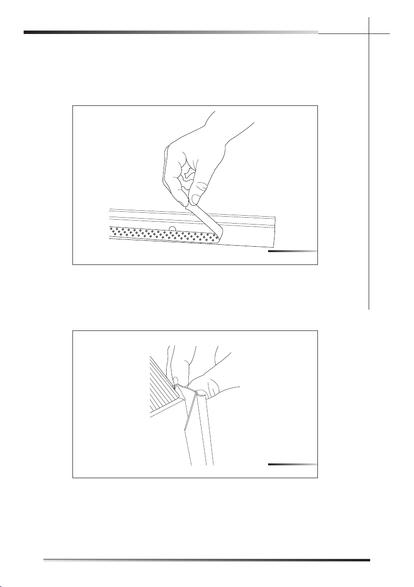
5.3.3 Completion of installation
Finish the cut with a fi le (see fi g. 5-25) in order to remove any burrs and/or
imperfections. Put back the base plate (see fi g. 5-26) and try to open the dish-
washer door fully; if the base plate still obstructs the door, repeat the above
operations.
Fig. 5-24
Fig. 5-25
Fig. 5-26
EN
28
INSTALLATION INSTRUCTION
5.3.3 Completion of installation
Finish the cut with a file (see fig. 5-25) in order to remove any burrs and/or
imperfections. Put back the base plate (see fig. 5-26) and try to open the dish-
washer door fully; if the base plate still obstructs the door, repeat the above
operations.
Fig. 5-24
Fig. 5-25
Fig. 5-26
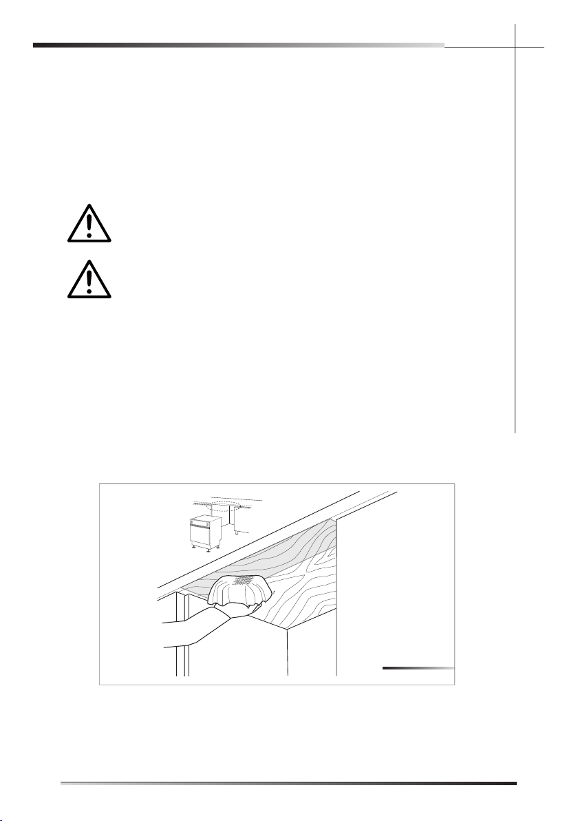
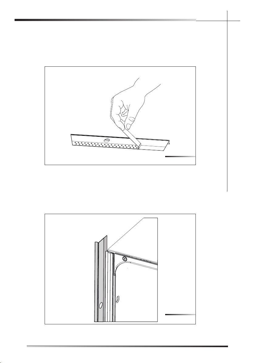
Before securing the dishwasher to the adjacent units, attach the gaskets to
the sides.
Remove the adhesive band on the gasket (see fi g. 5-27).
Fix the gasket to the dishwasher, inserting it in the seat on the sides towards
the front (see fi g. 5-28), and making sure that the long side of the gasket, the
one with the hole for inserting the screw, is attached to the outside of the dish-
washer; the hole in the long side must match the hole in the dishwasher (see
ref. A fi g. 5-29). Make sure the gasket adheres perfectly to the dishwasher.
Fig. 5-27
Fig. 5-28
EN
29
INSTALLATION INSTRUCTION
Depends on the models
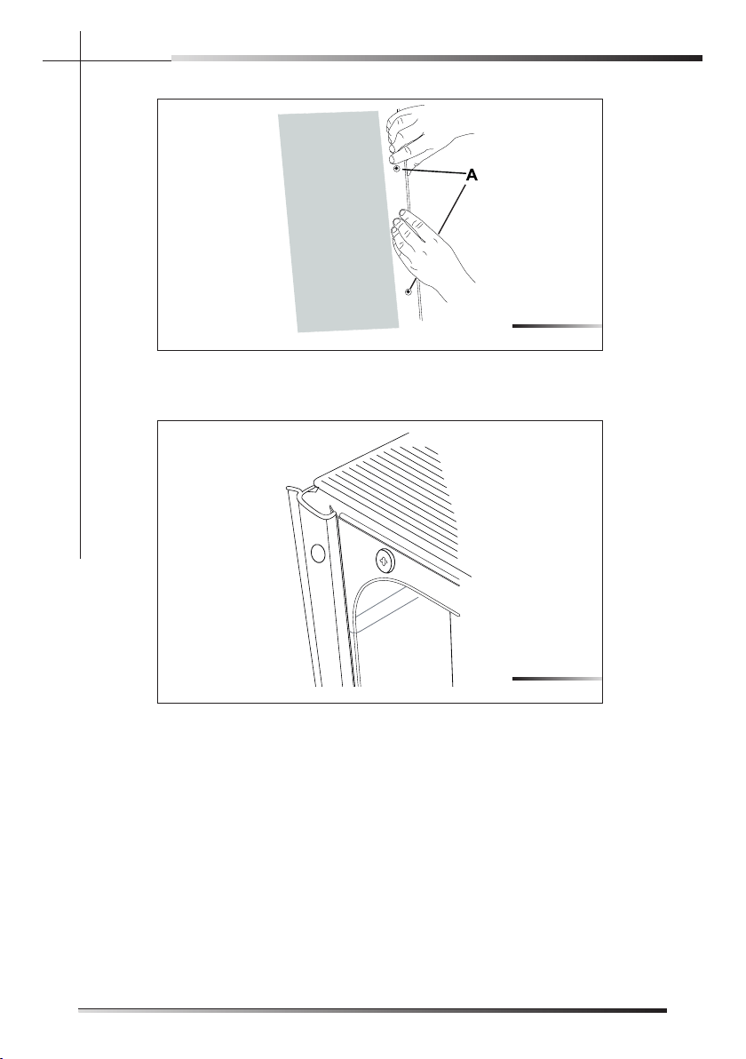
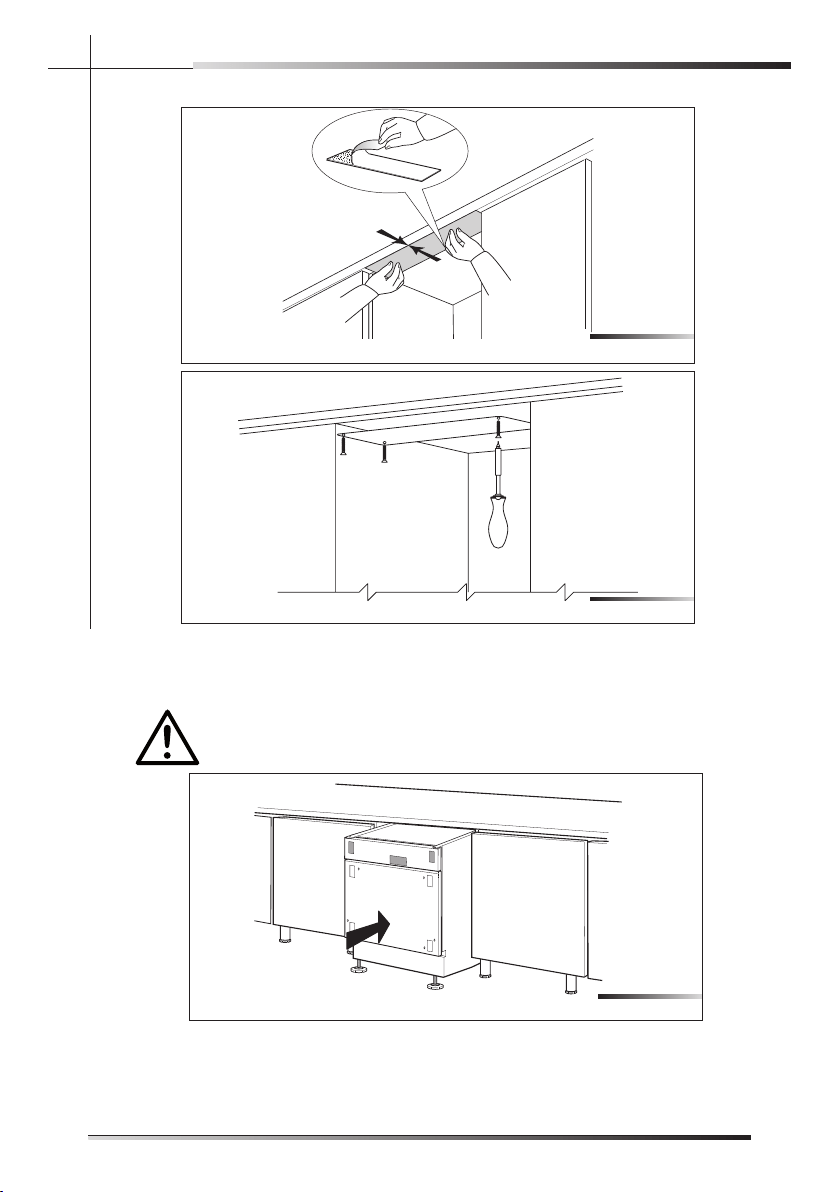
Fig. 5-30 shows the state of the dishwasher after the above operations are
performed.
Tighten the supplied screws with a screwdriver; this operation defi nitively fi xes
the dishwasher to the adjacent units; cover the side holes using the supplied
plugs (ref. A fi g. 5-31).
Fig. 5-29
Fig. 5-30
EN
30
INSTALLATION INSTRUCTION
5.3.3 Completion of installation
Finish the cut with a file (see fig. 5-25) in order to remove any burrs and/or
imperfections. Put back the base plate (see fig. 5-26) and try to open the dish-
washer door fully; if the base plate still obstructs the door, repeat the above
operations.
Fig. 5-24
Fig. 5-25
Fig. 5-26
Before securing the dishwasher to the adjacent units, attach the gaskets to
the sides.
Remove the adhesive band on the gasket (see fi g. 5-31).
Fix the gasket to the dishwasher, inserting it in the seat on the sides towards
the front (see fi g. 5-32), and making sure that the long side of the gasket, the
one with the hole for inserting the screw, is attached to the outside of the
dish-washer; the hole in the long side must match the hole in the dishwasher
(see ref. A fi g. 5-33). Make sure the gasket adheres perfectly to the
dishwasher.
Fig. 5-31
Fig. 5-32
EN
31
INSTALLATION INSTRUCTION
4
4
Depends on the models
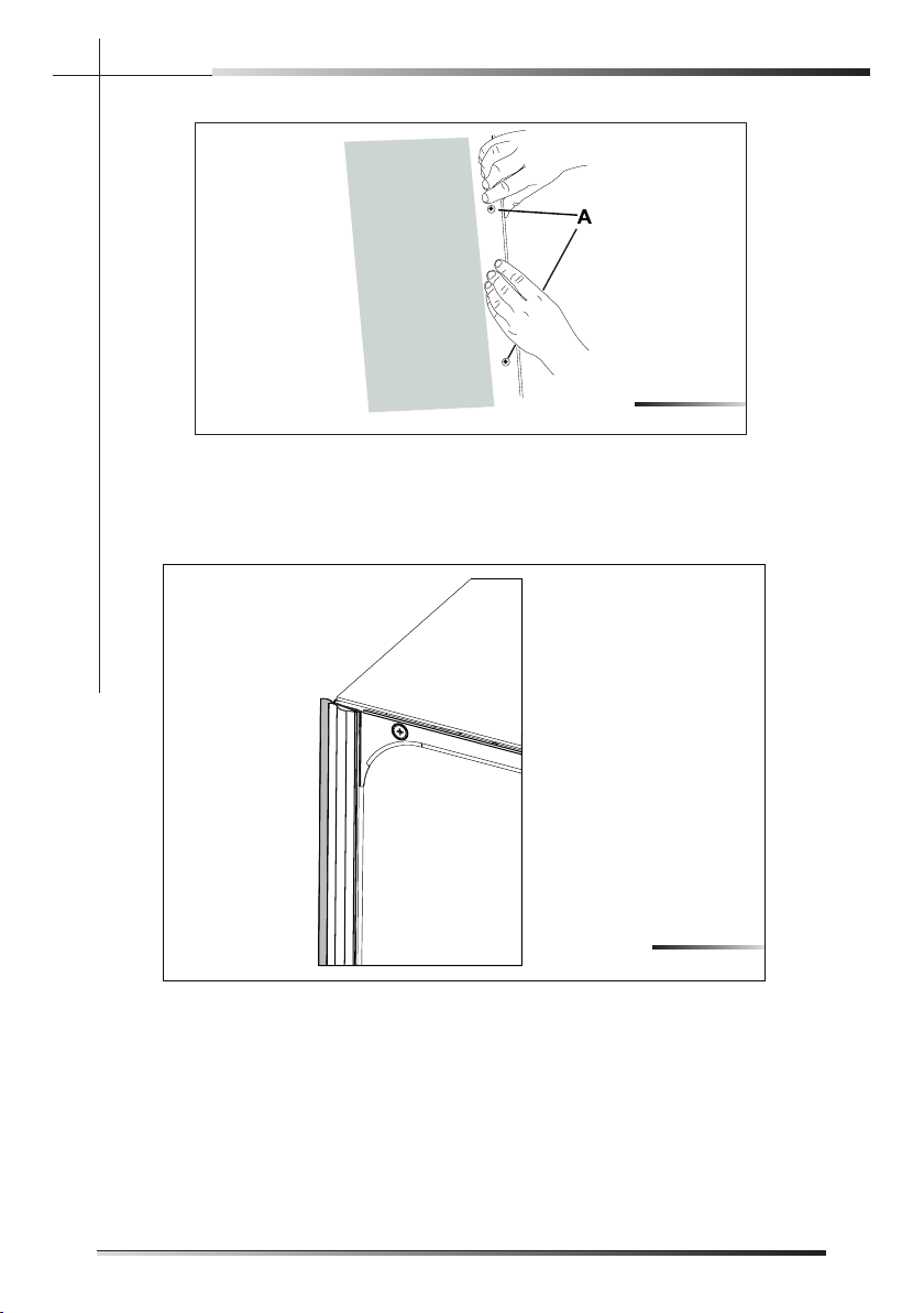
Fig. 5-34 shows the state of the dishwasher after the above operations are
performed.
Fig. 5-33
Fig. 5-34
EN
32
INSTALLATION INSTRUCTION
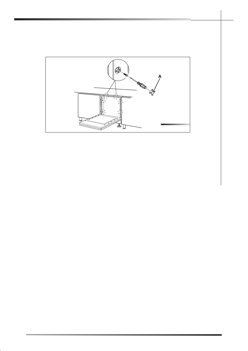
Fig. 5-30 shows the state of the dishwasher after the above operations are
performed.
Tighten the supplied screws with a screwdriver; this operation definitively fixes
the dishwasher to the adjacent units; cover the side holes using the supplied
plugs (ref. A fig. 5-31).
Fig. 5-29
Fig. 5-30
5.4 Testing
After installation, test the dishwasher by starting a work cycle. Check for leaks
and make sure the appliance does not malfunction.
Fig. 5-35
EN
33
INSTALLATION INSTRUCTION
Tighten the supplied screws with a screwdriver; this operation defi nitively fi xes
the dishwasher to the adjacent units; cover the side holes using the supplied
plugs (ref. A fi g. 5-35).

EN
34
