Loading ...
Loading ...
Loading ...
Page 13
4 in (101 mm)
7.05 in (179 mm)
5.35in(136mm)
1.45 in (37 mm)
11.4 in (290 mm)
1.95 in (49 mm)
Left rear wall
hole 2.5 in (65 mm)
Right rear wall
hole 2.5 in (65 mm)
Indoor unit outline
Model A
28.45 in (722 mm)
1.95 in (49 mm)
7.55 in (192 mm)
9.15 in (232 mm)
16.8 in (426 mm)
5.05in(128mm)
1.7 in (43 mm)
11.7 in (297 mm)
Left rear wall
hole 2.5 in (65 mm)
Right rear wall
hole 2.5 in (65 mm)
Indoor unit outline
Model B
31.6 in (802 mm)
1.7 in (43 mm)
1.7 in (43 mm)
5.65 in (144 mm)
2.3 in (58 mm)
12.55 in (19 mm)
2.25 in (57 mm)
40mm (1.55in)
Left rear wall
hole 2.5 in (65 mm)
Right rear wall
hole 2.5 in (65 mm)
Model C
38 in (965 mm)
5.45 in (138 mm)
1.35 in (34 mm)
Indoor unit outline
8.6 in (219 mm)
21.77 in (553 mm)
11.8 in (300 mm)
13.2 in (335 mm)
Left rear wall
hole 2.5 in (65 mm)
Right rear wall
hole 2.5 in (65 mm)
Model D
42.5 in (1080 mm)
2.1 in
(53.5 mm)
1.85in (47mm)
3in (76mm)
2.1 in (53.5 mm)
1.85 in (47 mm)
5.85 in
(148.7 mm)
5.95 in (151 mm)
6.85 in (174.3 mm)
Indoor unit outline
6.8 in (172 mm)
14.25 in (362 mm)
Left rear wall
hole 2.5 in (65 mm)
Right rear wall
hole 2.5 in (65 mm)
Model E
49.55 in (1259 mm)
Indoor unit outline
2.05 in (52 mm)
15.3 in (389 mm)
13.05 in (332 mm)
10.1in (257 mm)
25.3 in (643.6 mm )
2.05 in (52 mm)
Wall
Indoor Outdoor
m)m7-(5
0.2-0.3 in
Fig.3.2
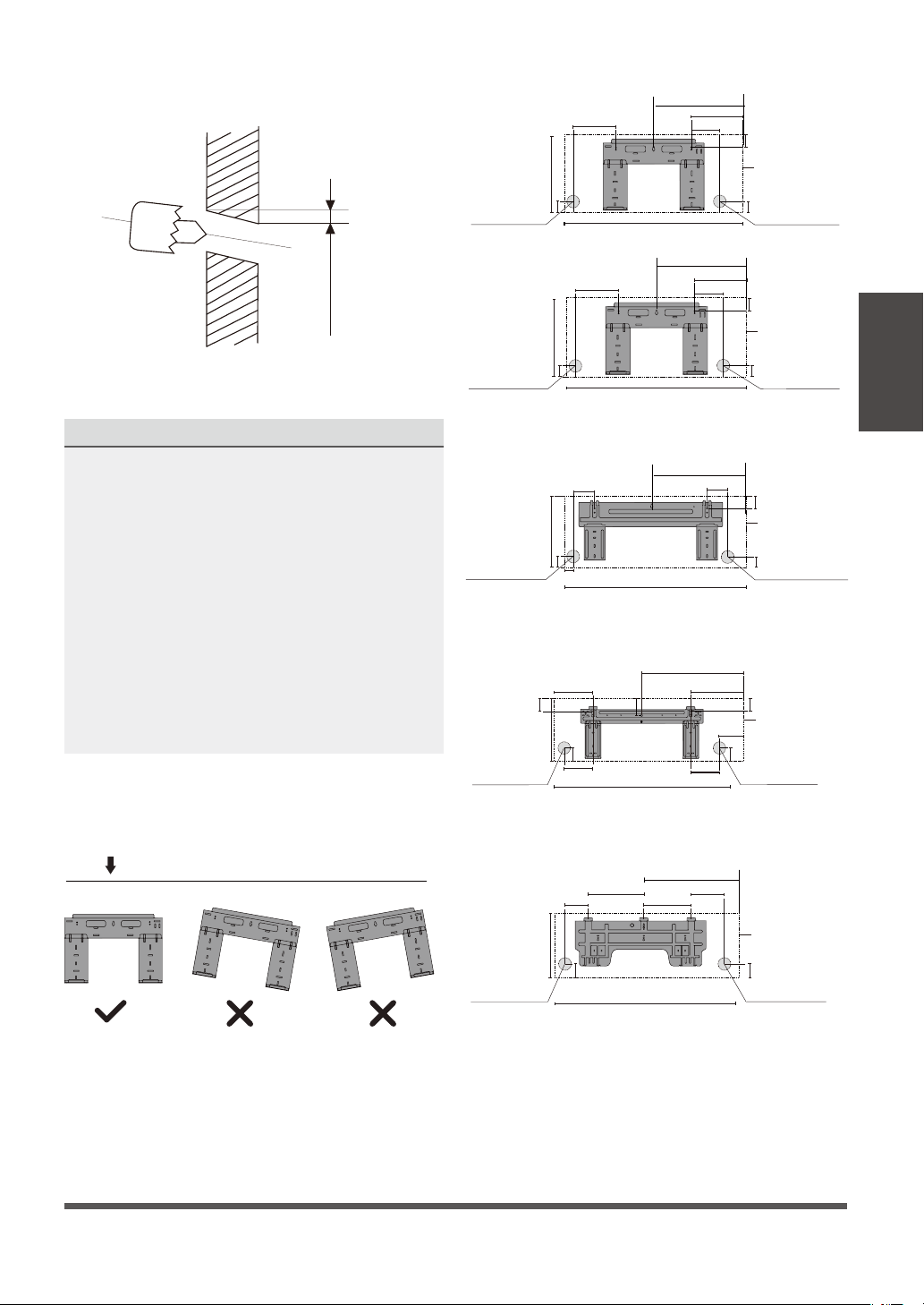
MOUNTING PLATE DIMENSIONS
Dierent models have dierent mounting plates.
In order to ensure that you have ample room to
mount the indoor unit, the diagrams to the right
show dierent types of mounting plates along
with the following dimensions:
• Width of mounting plate
• Height of mounting plate
• Width of indoor unit relative to plate
• Height of indoor unit relative to plate
• Recommended position of wall hole (both
to the left and right of mounting plate)
• Relative distances between screw holes
Indoor Unit
Installation
Fig. 3.2
Correct orientation of mounting plate
20.37 in (517.4 mm)
13.7 in (348.4 mm)
Loading ...
Loading ...
Loading ...