Loading ...
Loading ...
Loading ...
8
The ON/STOP SWITCH (8) is used to stop the
engine.
The THROTTLE TRIGGER (18) controls
engine speed.
The THROTTLE LOCK--OUT (16) must be
pressed before you can squeeze the throttle
trigger. This feature prevents you from
accidentally squeezing the trigger.
The choke and fast idle are set by pulling the
CHOKE/FAST IDLE LEVER (9) out to the full
extent for cold starting or after refueling. The
choke provides additional fuel to the engine
during cold starting.
The PRIMER (AIR PURGE) BULB (10)
circulates fuel to the carburetor to provide
quicker starting.
The CHAIN BRAKE (3) is a device designed to
stop the chain if kickback occurs. The chain
brake activates automatically in the event of
kickback. The chain brake activates manually if
the front hand guard is pushed forward. The
chain brake is disengaged by pulling the front
hand guard back toward the front handle as far
as possible.
ASSEMBLY
If received assembled, repeat all steps to
ensure your saw is properly assembled and all
fasteners are secure.
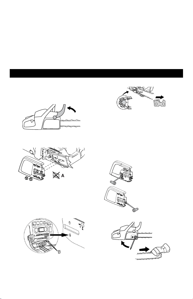
1. Check that the chain brake is in the
unlocked position by pulling the front hand
guard towards the front handle.
2. Loosen and remove the bar nuts and the
clutch cover from the saw.
3. Remove the plastic shipping spacer (A) if
present.
4. An adjusting pin and screw is used to adjust
the tension of the chain. It is very important
when assembling the bar that the adjusting
pin located on the adjusting screw aligns
into a hole in the bar. Turning the screw will
move the adjusting pin up and down the
screw. Locate this adjusting pin before you
begin mounting the bar onto the saw. See
following illustration.
5. Turn the adjusting screw by hand
counterclockwise until the adjusting pin is
positioned between the indicator marks (B)
on the clutch cover. This should allow the
adjusting pin to be near the correct position.
6. Slide guide bar with chain on bar bolts until
guide bar stops against clutch drum
sprocket. Cutters must face in the direction
of rotation.
7. Check that the drive links of the chain fit
correctly on the drive sprocket and that the
chain is in the groove on the bar.
8. Fit the clutch cover and insert the adjusting
pin in the cut-out in the bar.
9. Tighten the bar nut finger-tight.
10. Tension the chain by turning the chain
tensioning screw clockwise using the
combination tool. The chain is correctly
tensioned when it does not sag from the
underside of the bar, but can still be turned
easily by hand.
Chain tensioning-
side adjust models
Chain tensioning-
front adjust models
11. Hold up the bar tip and tighten the bar nuts
with the combination tool.
When fitting a new chain, the chain tension has
to be checked frequently until the chain is run-
in. Check the chain tension regularly. A
correctly tensioned chain ensures good cutting
performance and long life.
Loading ...
Loading ...
Loading ...