Loading ...
Loading ...
Loading ...
14
SETTING THE BURNER MINIMUM (Valves may vary)
When switching from one type of gas to another, the minimum flow rate must also be
correct: the flame should not go out even when passing suddenly from maximum to
minimum flame.
To regulate the flame follow the instructions below:
–
Light
the burner
–
Set
the gas valve to
LO position
–
Remove
the knob
– With a thin screwdriver, turn the regulation screw (Figs. 2.9a and 2.9b) until
adjustment
is correct. On some valves, you need to pass by the hole of the
micr
oswitch (Fig. 2.9a) to turn the regulation screw.
For LP/PROPANE gas, tighten the regulation screws completely.
Oven burner
13000 1500 109 180
Broil burner
8500 - 88 146
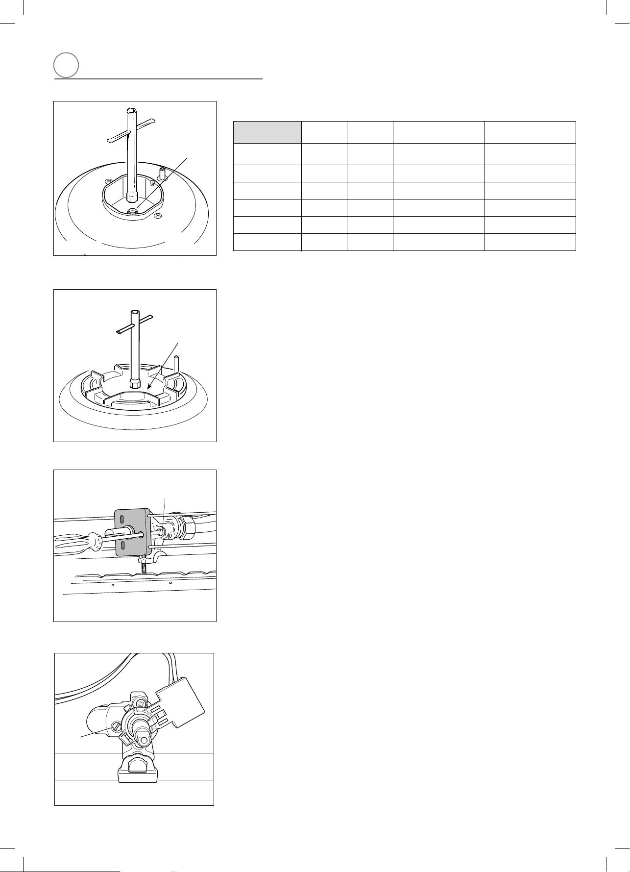
OPERATIONS TO BE PERFORMED WHEN SUBSTITUTING
THE INJECTORS
✓ Remove the gratings, the burner covers and the knobs;
✓ Using a wrench substitute the nozzle injectors “J” (figs. 2.7 - 2.8) with those most
suitable for the kind of gas for which it is to be used.
The burner are conceived in such a way so as not to require the regulation of the
primary air.
INJECTORS TABLE
NOMINAL
POWER
REDUCED
POWER
LP/PROPANE
11” W.C.P.
NATURAL GAS
4” W.C.P.
BURNERS
BTU/hr BTU/hr
Ø injector
[1/100 mm]
Ø injector
[1/100 mm]
Auxiliary (AUX)
3500 1000 55 90
Semirapid (SR)
6000 1500 72 118
Triple ring (TC)
12000 5000 102 170
Fig. 2.7
J
Fig. 2.8
J
2
Fig. 2.9a
Regulation screw
regulation screw
Regulation
screw
G
H
OR
Fig. 2.9b
Loading ...
Loading ...
Loading ...