
USER
MANUAL
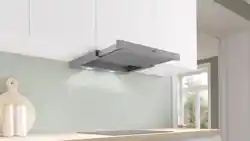
SLIDEOUT RANGEHOODS
IMPORTANT: Please ensure that you read through this user manual prior to installation and use. This
manual contains important information to ensure optimal performance and keep you safe. Please retain
your proof of purchase, as this will be required in the event that you require warranty service. Remember
to retain this manual for future reference.
LABEL HERE

WARNING & SAFETY INFORMATION
OPERATING INSTRUCTIONS
MAINTENANCE & TROUBLESHOOTING
INSTALLATION & DUCTING
CONTACT DETAILS
3
4
6
7
Cover
CONTENTS
2

• Do not ambe under the rangehood.
• Do not remove or inspect the lters
whilst the hood is in operation.
• You must read the details concerning
the method and frequency of cleaning.
DO’S & DONT’S
SAFETY WITH CHILDREN
TECHNICAL GUIDANCE
• This appliance is not intended for use
by persons (including children) with
reduced physical, sensory or mental
capabilities, or lack of experience and
knowledge, unless they have been
govern supervision or instruction
concerning use of the appliance by a
person responsible for their safety.
• Young children should be supervised
to ensure that they do not play with
the appliance.
• There shall be adequate ventilation
of the room when the rangehood is
used at the same time as appliances
burning gas or other fuels.
• There is a re risk if cleaning is not
carried out in accordance with the
instructions.
• Exhaust air must not be discharged
into an existing ue which is used for
exhausting fumes from appliances
burning gas or other fuels.
• The minimum distance between the
hob surface and the lowest part of the
rangehood is 600mm. This distance
shall be at least 650mm, if the
rangehood is installed over a gas hob.
If the instructions for the gas hob
specify a greater distance, this has to
be taken into account.
• Attention should be given to ensure
that any applicable regulations
concerning the discharge of exhaust
air is fullled.
• If the supply cord of this equipment is
damaged, it must only be replaced by
the manufacturer or its service agent
or a similarly qualied person in
order to avoid a hazard.
• This appliance has been designed for
indoor domestic use only.
• CAUTION: Accessible parts may
become hot when used with cooking
appliances.
WARNING & SAFETY INFORMATION
3
4
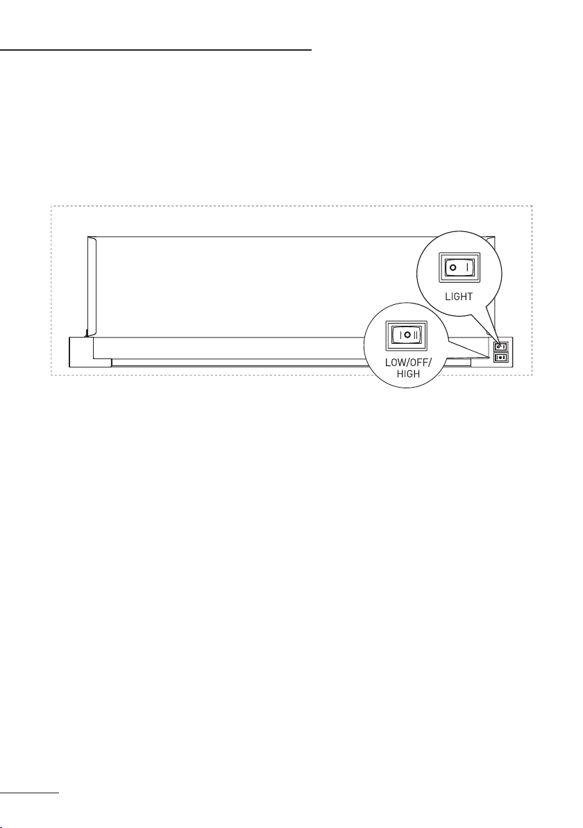
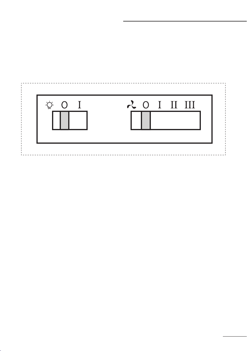
IMPORTANT: To operate the unit, ensure that the power is turned on and the front visor is fully extended.
This will provide access to the light and speed controls.
FAN SPEED
LOW/OFF/HIGH switch - Located on the right hand side of the unit.
This unit features 2 speed settings; single line indicate low speed, double lines indicate the high speed.
To turn the unit o, you can either slide the visor into the closed position or set the speed switch to the
middle position (o).
LIGHT
On/O switch - Located on the le hand side of the unit as indicated in the diagram above.
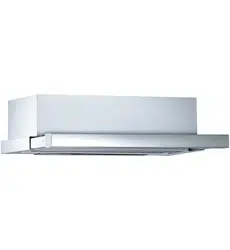
600 SLIDEOUT RANGEHOOD
OPERATING INSTRUCTIONS
NOTE: The lights turn o when the visor is closed.
LAMP TYPE: GU10 - 3W LED (x2)
5
IMPORTANT: To operate the unit, ensure that the power is turned on and the front visor is fully
extended.
FAN SPEED
OFF/LOW/MEDIUM/HIGH SLIDING SWITCH - Located on the right hand side of the control panel.
This unit features 3 speed settings; single line indicate low speed, double lines indicate the medium
speed & triple lines indicate high speed.
To turn the unit o, you can either slide the visor into the closed position or set the speed switch to the
0 position (o).
LIGHT
ON / OFF Sliding Switch - Located on the le hand side of the control panel as indicated in the diagram
above.
NOTE: The lights turn o when the visor is closed.
LAMP TYPE: GU10 - 3W LED (x2)
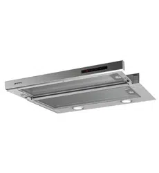
900 SLIDEOUT RANGEHOOD
OPERATING INSTRUCTIONS
CONTROL PANEL

6
Ensure that the power to the unit is switched o prior to cleaning the unit. The surface should only be
cleaned with warm soapy water and a so non-abrasive cloth. In coastal environments and humid areas
more frequent cleaning is required to maintain the nish.
GENERAL MAINTENANCE
FILTERS - 600 Slideout Rangehood
FILTERS - 900 Slideout Rangehood
The 600 Slideout Rangehood unit is supplied with Aluminium lters designed for ducted installations. Alu-
minium lters are dishwasher safe or can be cleaned with hot soapy water. Ensure that lters are thoroughly
dry before re-installing.
You may want to order Carbon lters designed to eliminate odours from the exhaust fumes when installing
the appliance for recirculating mode. This type of lter cannot be cleaned and should be replaced every 3-6
months depending on use.
The 900 Slideout Rangehood unit is supplied with Rectangular Carbon lters designed to eliminate odours
from the exhaust fumes when installing the appliance for recirculating mode. This type of lter cannot be
cleaned and should be replaced every 3-6 months depending on use.
You may want to order Aluminium lters designed for ducted installations. Aluminium lters are dishwasher
safe or can be cleaned with hot soapy water. Ensure that lters are thoroughly dry before re-installing.
LAMPS
Before replacing, ensure that the lamps are completely cool and the power to the unit has been switched
o. Replacement Lamps can be purchased from customer care. Contact details on front page.
To remove lamp, unscrew and remove the plastic cover, twist the bulb in an anti-clockwise direction. Be
careful when installing the new lamp not to make contact with the skin as this may damage the lamp and
shorten its life.
MAINTENANCE & TROUBLESHOOTING
7
10A plug fitte
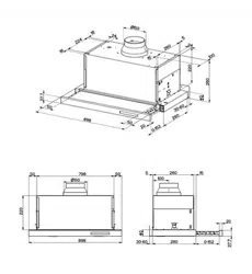
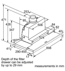
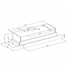
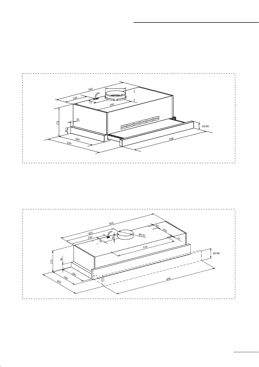
NOTICE: All measurements shown are to be used as a guide only, cutout dimensions should be taken from
physical product.
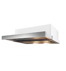
600 SLIDEOUT RANGEHOOD
900 SLIDEOUT RANGEHOOD
INSTALLATION & DUCTING
10A plug fitte
*
*Model Dependent
*
*Model Dependent
28
ø120
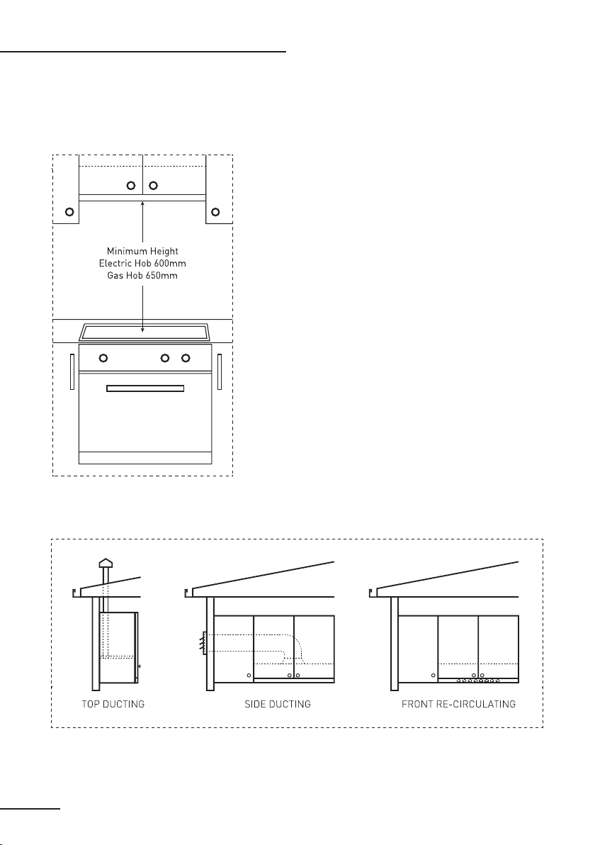
The image to the le, illustrates the minimum height from
the hob surface to the underside of the
rangehood.
Electric hob - 600mm
Gas hob - 650mm.
NOTICE: IF THE INSTRUCTIONS FOR THE GAS HOB
SPECIFY THE GREATER DISTANCE, THIS HAS TO BE
OBSERVED. ANY INSTALLATION ABOVE 750MM WILL
COMPROMISE PERFORMANCE.
INSTALLATION & DUCTING
8
IMPORTANT: Before handling the rangehood during the installation, it is recommended that you remove
the lter to prevent damage.
INSTALLATION & DUCTING
9
RECIRCUL ATIN G
DU CT ED
1. Remove the lter.
2. Optional - replace the 80mm front rail
with the 40mm front rail
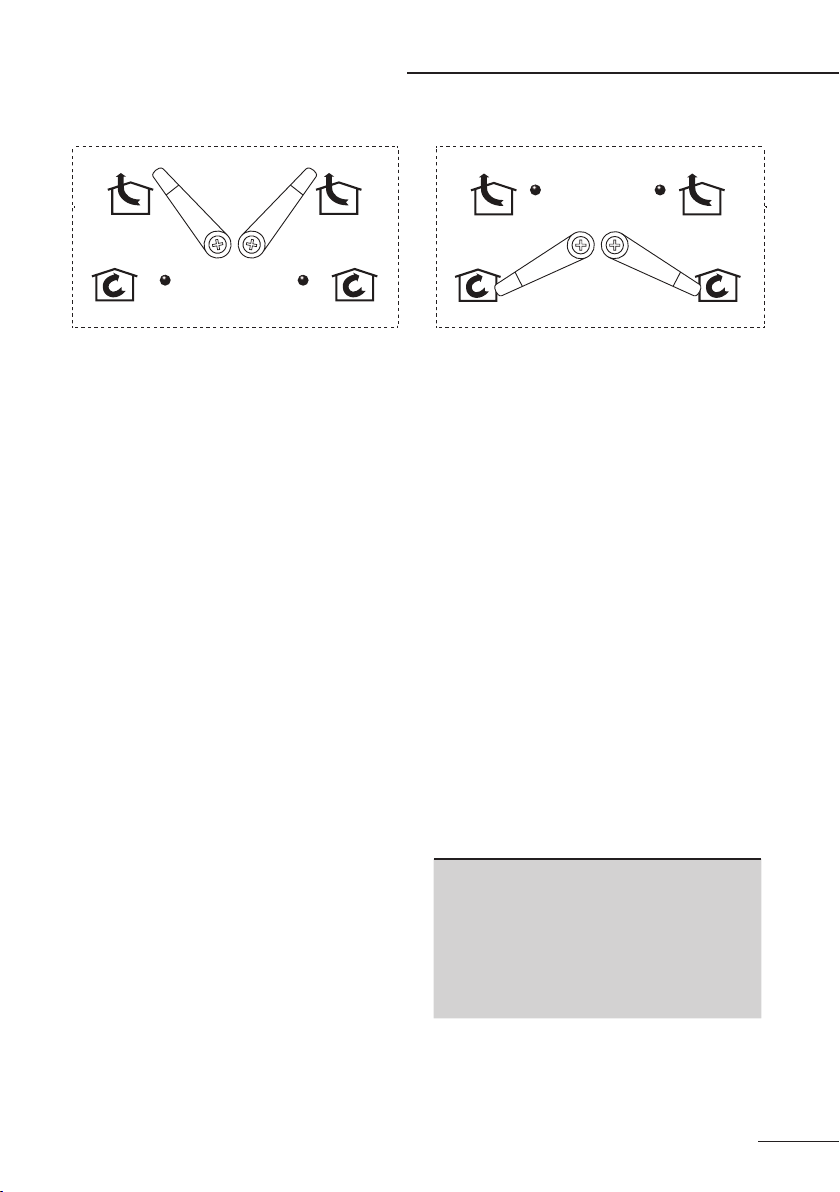
3. Make sure that the internal switch is in
ducted position. (see above)
4. Determine the most eicient path for
the ductwork, minimise bends and
keep the length of the ductwork to a
minimum.
5. Before xing the range hood, drill a
hole to accommodate the 125mm
ducting that you have selected.
6. It is important to run and nish (install
roof/ wall caps) prior to installation of
the hood.
7. Ensure that the access has been
allowed for the power cable and plug
aer installation.
8. Remove the 120mm ducting cover
plate and attach the ducting adaptor.
9. Hold the hood up to the underside of
the cabinet. Screw the rangehood to
the underside of the cabinet. Ensure
that you do not damage any of the
wiring during installation.
10. Attach the ducting adaptor to the
ducting.
11. Re-install lter.
12. Plug in the power to the unit, turn on
and test.
1. Remove the lters.
2. Remove the front vents. Do not
remove the top 120mm outlet cover.
3. Make sure that the internal switch is in
recirculating position. (see above)
4. Drill 4 xing holes as per the drawing.
Ensure that the access has been
allowed for the power cable and plug.
5. Hold the hood up to the underside of
the cabinet with the corresponding
holes in the hood. Screw the 4 screws
from the cabinet side.
6. Re-install lters.
7. Plug in the power to the unit, turn on
and test.
Note: When the rangehood is re-circulating.
carbon lters must be installed.
(See Maintenance & Troubleshooting)
WARNING: DO NOT penetrate any screws
into the range hood as this may result in
electrical hazards.
WARNING: Failure to install the screws
or xing devise in accordance with these
instructions may result in electrical hazards.
DUCTED OPTION
(if your model permits)
RE-CIRCULATING OPTION
(if your model permits)
10
NOTES
NOTES
11

We are committed to ongoing research and development. Every eort has been made to ensure all
information in the user manual is correct at time of going to print. Dimensions should be used as a reference
only and actual dimensions should be taken from the physical product.
Version 1.8