
INSTALLATION · OPERATION · MAINTENANCE GUIDE
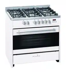
UPRIGHT COOKERS
SCU900B, SCU900R, SCU900CR,
SCU900DB, SCU900BG, SCU900S,
SCU900LG, SCU900PB

Page 2
Index
1. Welcome ......................................................................................................................................... 3
2. Your Safety — General Warnings .................................................................................................... 4
3. Installer’s Guide .............................................................................................................................. 6
Cooker Installation.............................................................................................................................................. 6
Gas Connection .................................................................................................................................................. 9
Electric Connection ............................................................................................................................................ 10
To Fit The Stabilising Chains .............................................................................................................................. 11
Conversion to Other Type of Gas ...................................................................................................................... 12
Gas Taps/Valves Maintenance and Cleaning ................................................................................................... 13
Before Leaving Completed Installation ............................................................................................................ 13
4. User’s Guide .................................................................................................................................... 14
Preliminary Advice .............................................................................................................................................. 14
How to Use Burners of The Cooking Top ......................................................................................................... 15
How to Use The Electric Multi-function Oven .................................................................................................. 17
Oven Light Use ................................................................................................................................................... 18
Electronic Programmer ...................................................................................................................................... 18
General Remarks ................................................................................................................................................. 22
Recommendation for Using the Oven and the Grill ........................................................................................ 23
5. Instructions for Maintenance and Cleaning ..................................................................................... 25
General Cleaning ................................................................................................................................................ 25
Cleaning the Burners .......................................................................................................................................... 25
Oven Cleaning .................................................................................................................................................... 26
Replacing The Oven Bulb .................................................................................................................................. 27
Protection Filter of the Oven Fan ...................................................................................................................... 27
Remove The Pan Side of Oven .......................................................................................................................... 28
Remove the Oven Door for Cleaning ............................................................................................................... 29
6. Control of The Product ................................................................................................................... 30
7. Tables .............................................................................................................................................. 31
8. Technical Characteristics ................................................................................................................. 32
9. Troubleshooting .............................................................................................................................. 33
Gas Burners ......................................................................................................................................................... 33
In Case of Emergency ........................................................................................................................................ 33
10. Disclaimer ....................................................................................................................................... 34
Page 3
1. Welcome
Welcome
Thank you for purchasing this Scandium appliance.
To get the optimal performance from your appliance, and to avoid the risk of accidents or damage, it is
essential to read this manual before installation and rst time use.
This guide contains important information on the use and maintenance of the appliance, as well as important
safety notes.
Your appliance has been thoroughly checked for safety and functionality before being packaged and leaving
the manufacturer.
Please keep this instruction manual in a safe place so you can refer to it at any time.
ATTENTION
Installation, regulation or maintenance, both gas and electric, should only be
executed by qualied and authorised personnel who are aware of the installation
regulations in force.
Please make sure to read this booklet carefully, containing general instructions for the
Installation, Use and Maintenance of your cooker, before installing and using it.
It will be extremely useful to know in detail the best way of operating and maintaining
this appliance so that you will enjoy its benets and be assure of best results.
Keep this instruction booklet with the appliance in case you pass it on to someone
else.

Page 4
2. Your Safety — General Warnings
Please read the following carefully, as these warnings are provided in the interest of safety. You MUST read
them carefully before installing or using the appliance.
• It is important that this instruction book be retained with the appliance for future reference. Should the
appliance be sold or transferred, always ensure that the book is left with the appliance in order that the new
owner can get to know the functions of the appliance and the relevant warnings.
• This appliance is designed for domestic use only. It must be used by adults. Do not allow children to play
with it. The front accessible parts of the equipment could overheat during use.
• The appliance is not intended for use by persons (including children) with reduced physical, sensory or
mental capabilities, or lack of experience and knowledge, unless they have been given supervised or
instruction concerning use of the appliance by a responsible person for their safety.
• Young children should be supervised to ensure that they do not play with the appliance.
• In order to prevent accidental tipping of the appliance, for example by a child climbing onto the open
oven door, the stabilising means must be installed. Please refer to instructions for installation.
• Ensure the appliance is switched off before replacing the oven lamp to avoid the risk of electric shock.
• If the surface is cracked, switch off the appliance to avoid the possibility of electric shock.
• During use the appliance becomes hot. Care should be taken to avoid touching heating elements inside the
oven.
• Accessible parts may become hot during use. To avoid burns and scalds, young children should be
kept away.
• Do not use harsh abrasive cleaners or sharp metal scrapers to clean the oven door glass since they can
scratch the surface, which may result in the glass shattering.
• The appliance is not intended to be operated by means of an external timer or separate remote-control
system.
• The instructions shall state that, the means for disconnection must be incorporated in the xed wiring in
accordance with the wiring rules.
• Do not spray aerosols in the vicinity of the appliance when it is in operation.
• Do not store or use ammable materials in the appliance, storage drawer or near this appliance.
• Do not modify this appliance.
• Always turn the grill off immediately after use as fat left there may catch re.
• Do not cover the inside of the oven with foil, as fat left there may catch re.
• Always keep the grill dish clean as any fat left there may catch re.
• Do not leave the grill on unattended.
• To avoid a re, ensure that grill trays and ttings are always inserted into the appliance in accordance with
the instructions.

Page 5
2. Your Safety — General Warnings
• Switch the appliance off before removing the oven light glass for globe replacement.
• To avoid an accident, ensure that oven shelves and ttings are always inserted into the appliance in
accordance with the instructions.
• Do not use the door as a shelf.
• Do not push down on the open oven door.
• Do not allow large cookware to overhang the hob onto the adjacent benchtop. This will cause scorching to
the benchtop surface.
• An authorised person must install this appliance.
• Before using the appliance, ensure that all packing materials are removed from the appliance.
• In order to avoid any potential hazard, the installation instructions must be followed.
• Ensure that all specied vents, openings and airspaces are not blocked.
• Only authorised personnel should carry out servicing.
• Always ensure the appliance is switched off before cleaning or replacing parts.
• Always clean the appliance immediately after any food spillage.
• To maintain safe operation, it is recommended that the product be inspected every ve years by an
authorised service person.
• If the supply cord is damaged, it must be replaced by the manufacturer or its service agent or similarly
qualied person in order to avoid a hazard.
• Never use the food-warmer drawer set at bottom of the cooker to store ammable substances or
materials that cannot withstand heat such as wood, paper, spray cans, rags, etc.
• This appliance is unsuitable for use in marine craft, caravans or mobile homes.
• This appliance must not be installed behind a decorative door in order to avoid overheating.

Page 6
3. Installer’s Guide
Cooker Installation
This appliance should only be installed by authorised persons and in accordance with the manufacturer’s
installation instructions, local gas tting regulations, municipal building codes, electrical wiring regulations,
local water supply regulations, AS/NZS 5601 - Gas Installations and any other statutory regulations.
The manufacturer declines any and all responsibilities for damages to property or injuries to persons or
animals deriving from incorrect installation or use of equipment.
Ventilation must be in accordance with AS/NZS 5601 - Gas Installations. In general, the appliance should
have adequate ventilation for complete combustion of gas, proper ueing and to maintain temperature of
immediate surroundings within safe limits.
• The gas and electricity conditions are indicated in labels near the gas / electricity inlets.
• The appliance must be installed in places with proper conditions relative to dimensions, ventilation and
exhaust of combustion products.
• The air must not be discharged into a ue that is used for exhausting fumes from appliances burning gas or
other fuels (not applicable to appliances that only discharge the air back into the room).
• The installation site should have a permanent discharge of combustion products to the outside.
• Airow must be direct via permanent openings.
• The air ow can also be obtained by indirect path via the installation sites adjacent to desired locations such
that possess direct ventilation are not local re hazard and are not bedrooms.
• The air ow between the adjacent location and the installation location shall take place freely through
permanent openings (for example, obtainable by increasing the space between the door and the oor).
• The inlet air must have a minimum cross section of 100cm
2
and must not be unintentionally obstructed.
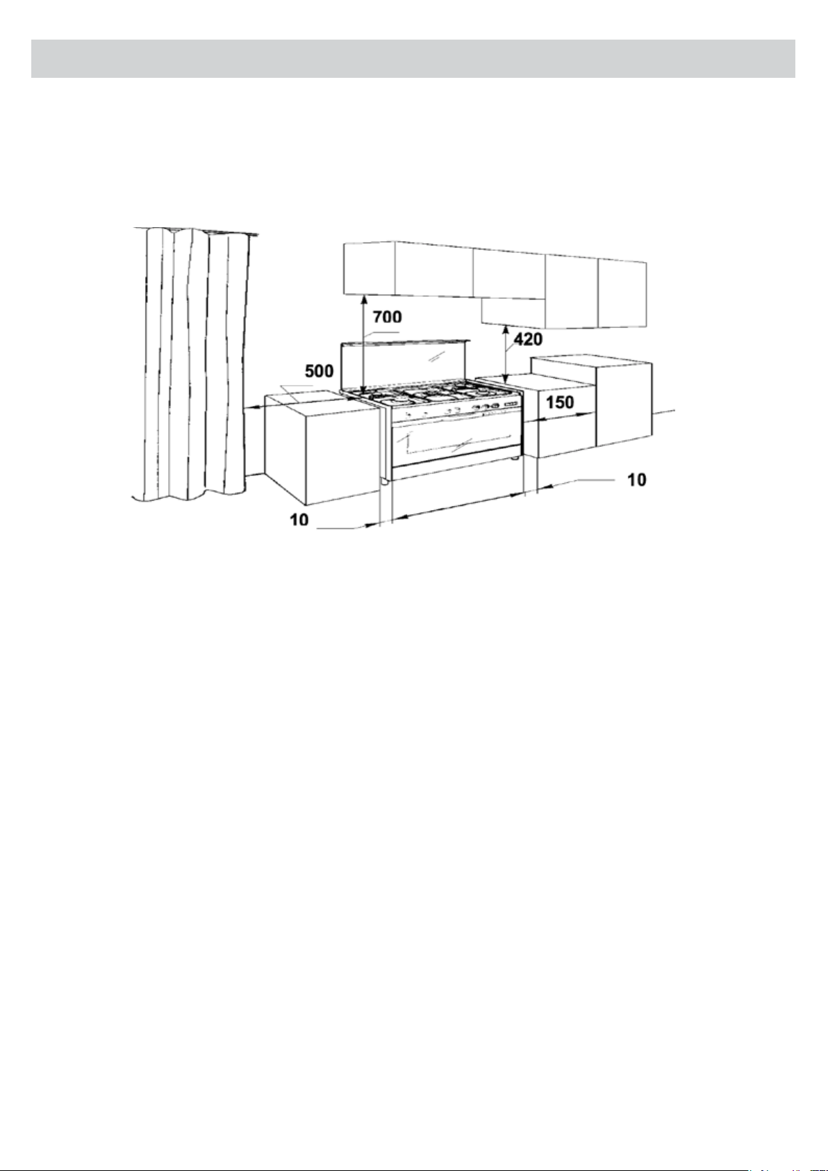
• Any adjoining wall surface situated within 200mm from the edge of any hob burner must be a suitable non-
combustible material for a height of 150mm for the entire length of the hob. Any combustible construction
above the hotplate must be at least 700mm above the top of the burner and no construction shall be within
450mm above the top of the burner. Zero clearance is permitted on side and rear adjoining surfaces below
the hob.
• The walls of the sided furniture must resist a temperature 75ºC higher than ambient temperature.
• The back wall must be of non-combustible material.
• Combustible materials, like curtains must be at the minimum distance of 500mm.
• The furniture to the side of the cooker, if higher than the cooking plan, must be at a minimum distance of
150mm from the side of the appliance - unless that surface is constructed of a suitable non-combustible
material for the entire length of the cooking surface.
• Any horizontal surface situated within 200mm from the edge of any hob burner must be a minimum of
10mm below the cooking surface or else comply with the above.
Page 7
• Any rangehood above the cooker must be installed according to the manufacturer’s instructions, and with a
minimum distance of 650mm from the cooking surface.
• Before installing the cooker, remove the protective plastic sheathing covering some metal parts.
• Do not put in the compartment located underneath the oven, ammable materials (example: oils, plastics,
paper, etc).
• The cooker foundation, must prevent rolling.
• The cooker should not be used without the legs installed into the base of the cooker
3. Installer’s Guide
• If the cooker is installed under suspended elements. There should be a minimum 700mm of distance from
the cooking surface, see Federal and State government guidelines.
• The furniture over and to the side of and above the appliance must have a minimum clearance of 420mm
from the cooking surface, see rangehood installation guide.
Page 8
3. Installer’s Guide
Gas Connection
The cooker is provided with a rating plate placed on the rear panel near the gas inlet, showing the type of gas
and pressure for which the appliance has been originally adjusted.
Before connecting this appliance, check if it is prepared for the type of gas and pressure available in the home.
If not, it is necessary to convert the appliance to another gas type as indicated in the Tables section.
This appliance is suitable for connection to Natural and Universal LPG (ULPG). Refer to gas pressure shown on
the data plate and in the Tables section.
The appliance must be connected to the gas supply or the cylinder, according to Australian Standards.
The gas connection is male 1/2” BSP and is situated 55mm from the right and 550mm from the oor. There are
two ways to connect to the main gas line:
A. The Cooker can be connected with rigid pipe as specied in AS/NZS 5601 table 3.1.
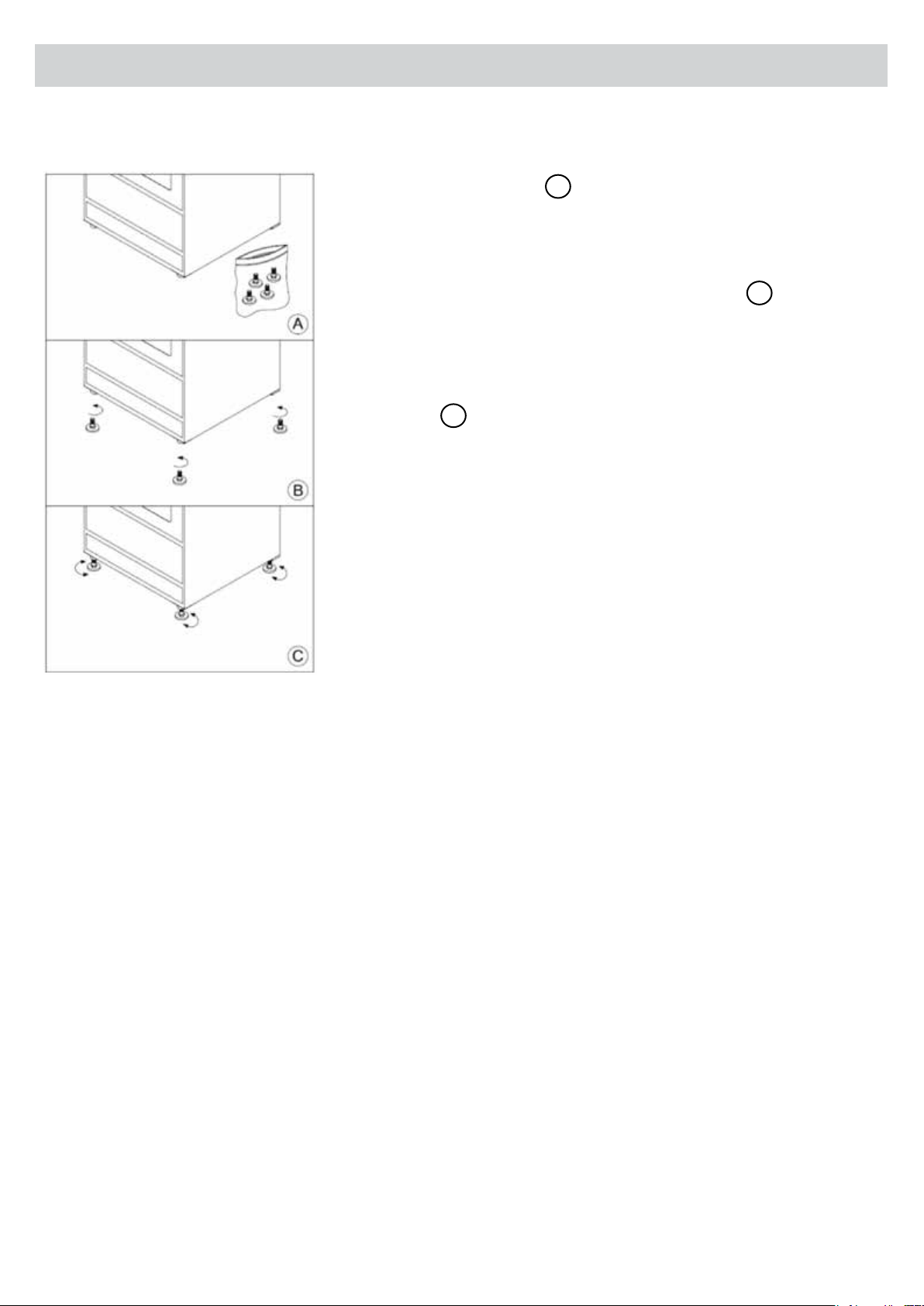
The cooker must be installed securely and level.
• Use the leg accessories
A
.
• You will require an assistant to lift one side of the unit.
• Never invert the unit.
• Screw leg at corner holes below unit one at a time
B
.
• You will require an assistant to lift the other side of the unit. Screw
the other two legs the same way before at different corners.
• Adjust height of leg by turning lower portion clockwise or counter-
clockwise
C
.
NOTE: Unit must be level.
Page 9
3. Installer’s Guide
ATTENTION
• Ensure the tube is not bent or twisted.
• Ensure the tube is not in contact with the rear panel.
• The tube must be replaced before expiry date.
• The whole length of the tube must be checked.
• The maximum length of the exible rubber tube is 1200mm.
• Check all connections for gas leaks with soap and water. DO NOT use a naked
ame for detecting leaks.
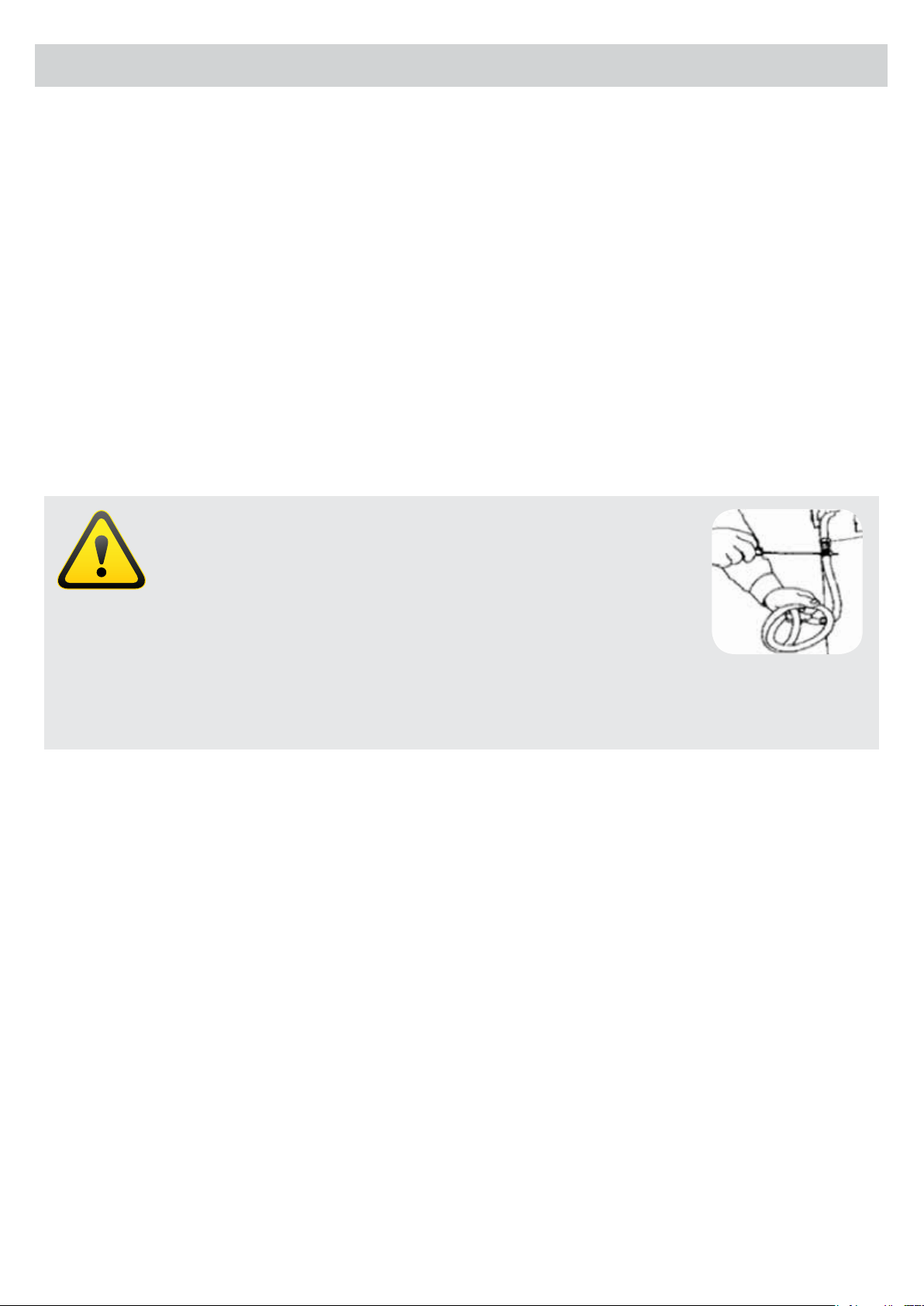
B. The cooker can be connected with a Flexible Hose. The hose must be certied to AS/NZS 1869, 10mm ID,
class B or D, between 1 - 1.2m long and in accordance with AS/NZS 5601 for a high level connection. The hose
should not be subjected to abrasion, kinking or permanent deformation and should be able to be inspected
along its entire length. Unions compatible with the hose ttings must be used and connections tested for gas
leaks. The xed consumer piping outlet should be at approximately the same height as the cooker connection
point, pointing downwards. The hose should not touch the oor when the cooker is in the installed position.
Fix one end of the chain on the screw next to the gas inlet connection and the other end should be anchored
to the oor/wall so that the chain prevents strain on the hose connections when he cooker is pulled forward.
The appliance is factory set for Natural gas. The test point pressure should be adjusted to 1.00kPa with the
Wok burner operating at maximum.
The connection to the cooker should be on the same side of the point of feeding, in a way that the tube
doesn’t cross the back of appliance. If necessary, change the gas inlet or adapt the tube so that the entrance
of gas in the appliance is on the correct side.
Page 10
3. Installer’s Guide
Electric Connection
IMPORTANT
The appliance must be always connected to ground, according to actual regulations.
The electric connection, should be executed only by qualied personnel who are aware of
installation regulations in force.
This appliance requires a hard wired direct connection to the mains (cable without plug), it is necessary to
insert a suitable omnipolar switch before the appliance, with minimum opening between contacts of 3mm (the
grounding wire should not be interrupted by the switch).
Before connection make sure that:
• The electric network is prepared for the required power (see the data plate, or table of
technical characteristics).
• The appliance must always be grounded in accordance with the regulations in force.
• The earth connection conductor is green/yellow.
• The socket or the omnipolar switch can easily be reached after the installation of the oven.
• The supply cable must be positioned so that no point can reach a temperature at 50ºC higher than the
ambient temperature.
• Never use reductions, shunts, adaptors which can cause overheating or burning.
• The appliance is equipped with a power cord designed to operate at a frequency of 50/60Hz.
• Verify the type of electric connection in the label placed on the rear side of the appliance near the cable
inlet, in the data plate placed in the dish warmer door, in the package label or in the characteristics table of
technical characteristics.
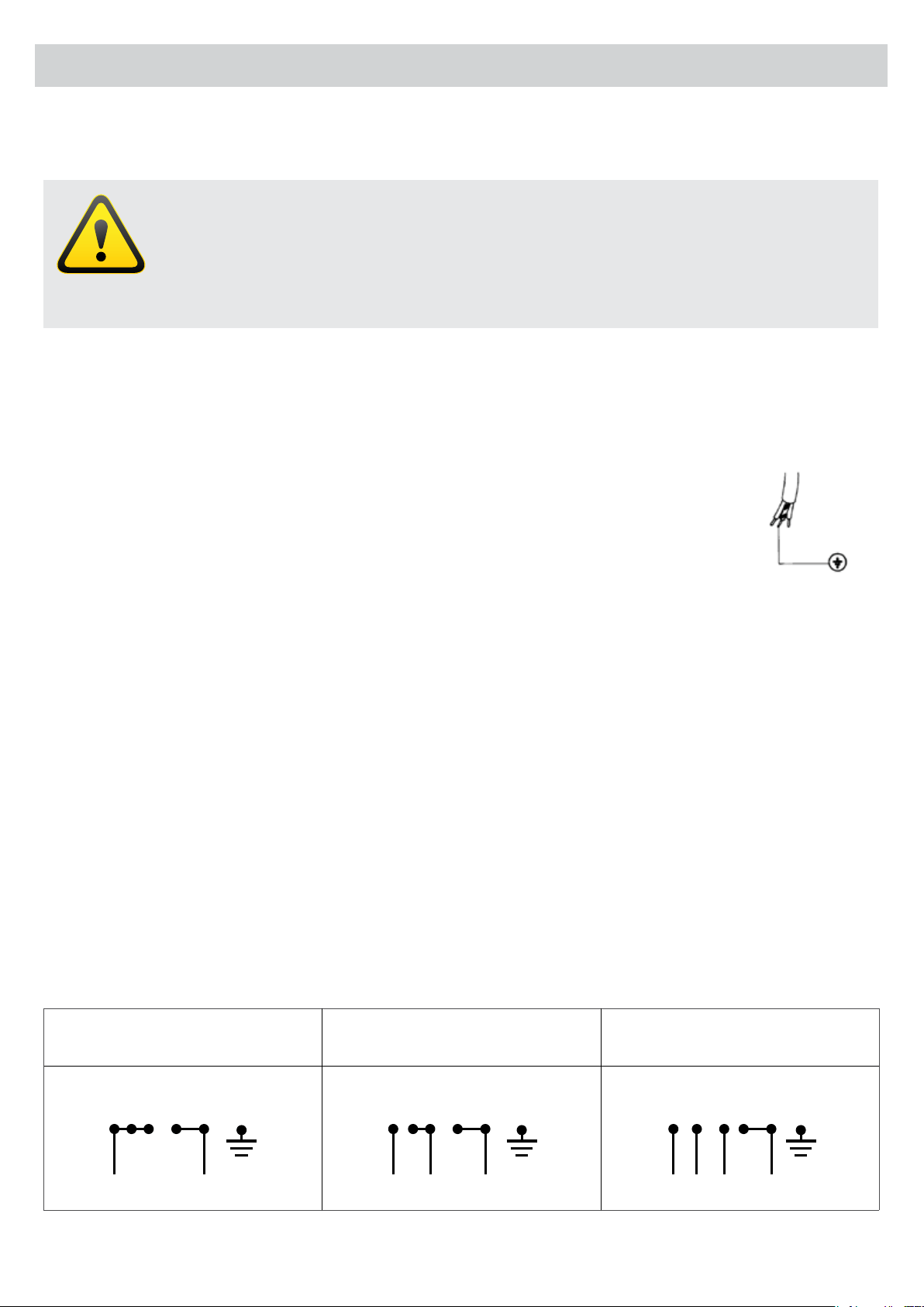
• According to the models, see table of technical characteristics, the connection could be, 230 - 240V ~,
single-phase current (2+1 conductors) or 400V 2N ~, two-phase current (3+1 conductors), or three-phase
current 400V 3N ~ (4+1 conductors).
• Ensure the connection cable is adequate, for monophasic type HO5VV-F and triphasic type HO5RR-F.
To proceed, refer to the diagram below:
monophasic 220 - 240V
2 + 1 conductors
biphasic 380 – 415V 2N
3 + 1 conductors
triphasic 380 - 415V 3N
4 + 1 conductors
L
R S T
N
N
1 2 3 4 5
L1 L2
R S T
N
N
1 2 3 4 5
L1 L2 L3
R S T
N
N
1 2 3 4 5
NOTE: The distributor is not responsible for eventual direct or indirect damages owing to a wrong installation,
regulations misunderstanding or standards in force not respected.
Page 11
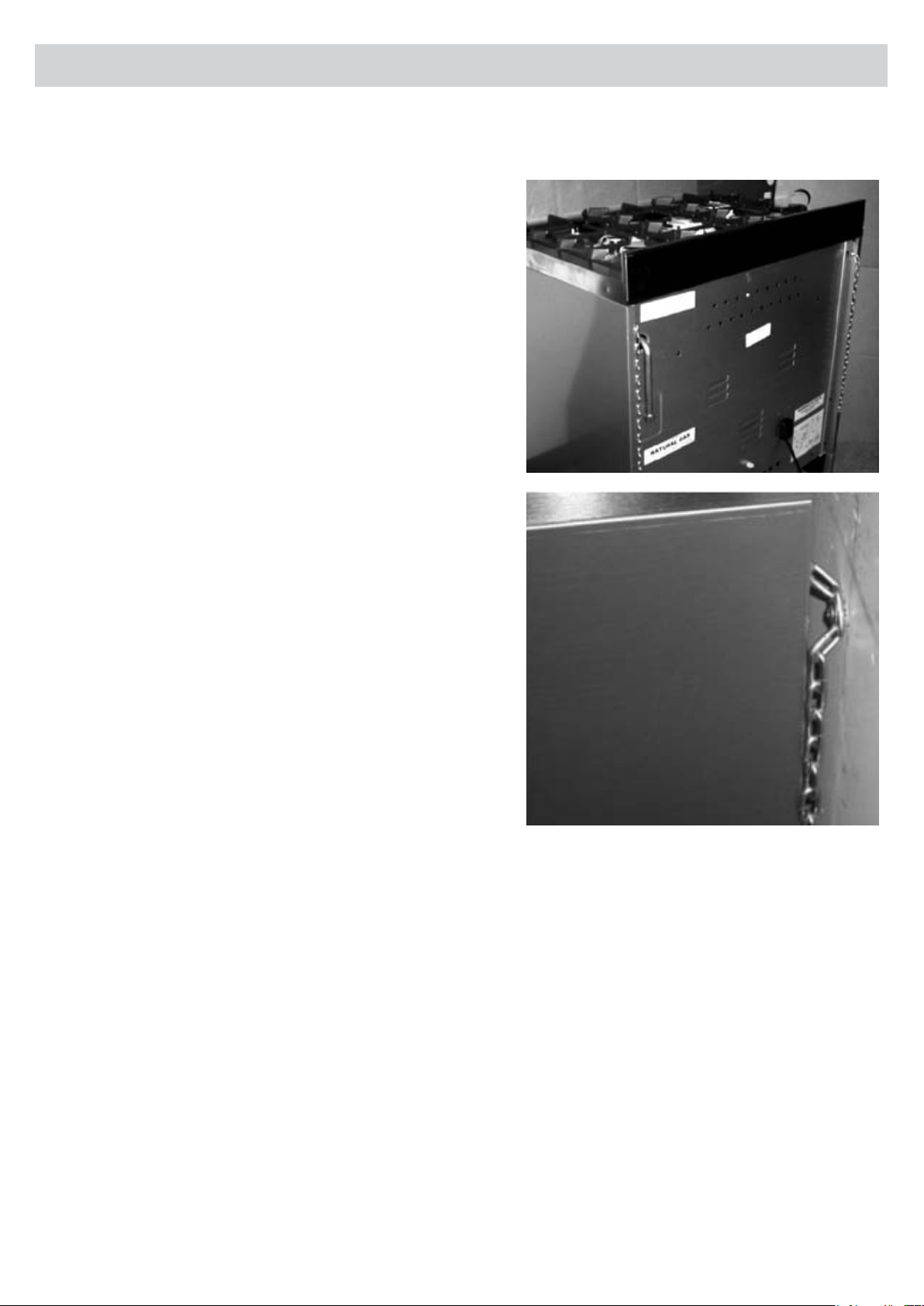
3. Installer’s Guide
To Fit The Stabilising Chains
In order to prevent tipping of the appliance it is equipped
with 2 chains for stabilising means and must be installed and
is required for safety reasons.
After the connection to gas and electrical supply is
completed and oven is located in its nal position. The
following MUST be done:
The 2 chains are tted in the upper part of the rear right and
the rear left side. These two chains enable the cooker to be
xed to the wall.
1. The anchor used to attach the chains to the rear wall
must be of a type suitable for the purpose.
2. If the appliance is installed between two cupboards, drill
a hole big enough on each side of the cupboards, to
allow the chains to pass through the holes and anchor
the chains within each cupboards.
3. If the appliance is installed next to drawers, remove
the drawers, then carry out the procedure described in
point 2. Ensure the anchor does not interfere with the
operation of the drawers. If the cooker is to be installed
next to an appliance, such as a dishwasher, temporarily
remove the appliance for access to t the stabilising
chains.
4. Make sure the xing to the wall is as close as possible
to the chain anchor point on the cooker and that the
chains are taught to effectively prevent the appliance
from tilting.
When the oven is moved for servicing, THE CHAINS MUST BE RE-ATTACHED by the technician.
Page 12
3. Installer’s Guide
Conversion to Other Type of Gas
This operation must be executed by qualied and authorised personnel.
This appliance has been designed to function with ULPG or Natural gas.
This appliance is provided with a label on the rear panel, near the gas inlet, indicating the type of gas and
pressure for which the cooker has been adjusted.
The indication of the gas and pressure that the cooker has been adjusted to can also be found on the data
label or on the package of the appliance. Choose Inlet gas connection according to the type of gas available
in your home.
1. To adapt the appliance to a gas different from that for which it was set up proceed as follows:
1.1 remove the grids
1.2 remove the burners caps and burner heads
1.3 with a 7mm socket spanner unscrew and remove the injectors.
1.4 replace the injectors with those supplied corresponding to the gas available (see burner and injector
characteristics in the Tables section)
1.5 replace the various parts proceeding in reverse.
2. Move the air regulator which is input to the burner near the injector to increase or decrease the air
passage.
3. The ame on the small output is regulated in the factory. When the injectors have been replaced or there
are special mains pressure conditions, it may be necessary to regulate the minimum again. The operations
necessary to perform this operation are the following:
3.1 Light the burner on and put the knob to the Low Position.
3.2 In this position, remove the knob of the tap.
3.3 With a screw driver adjust the tap screw until the ame is conveniently regulated
to the low position and stable
3.4 Reassemble the knob and pass quickly from the Full On Position to the Low Position,
several times, to ensure that the ame remains stable.
3.5 For burners with a safety valve make sure that the regulation obtained is sufcient to
maintain heating of the thermocouple. If it is not, increase the minimum.
• After connecting the unit, check for gas leaks with soap and water solution, NEVER USE A FLAME.
• Place, near the inlet gas connection, a label indicating the type of gas for which the appliance is now
prepared. “Appliance prepared for...“
• When converting from Natural Gas to Propane ensure that the NG regulator is removed and replaced with
the Test Point Assembly. A gas regulator suitable for a supply pressure of 2.7kPa should be part of the gas
tank supply and the test point pressure should be adjusted to 2.75kPa. Replace the old data plate with one
that is suitable for the type of gas for which the appliance has been converted.

Page 13
Gas Taps/Valves Maintenance and Cleaning
• Before any operation disconnect the appliance electrically. Wash the enamelled parts with lukewarm water
and detergent. Do not use abrasive products.
• Wash the burner spreader frequently with boiling water and detergent being sure to remove any deposits
which could block the ame outlet. Rinse the stainless steel parts well with water and dry them with a soft
cloth.
• To clean the hob use slightly damp sponges and wiping cloths: if too much water is used it could penetrate
the internal parts and damage electrical parts.
• The grids of the hob can be washed in the dishwasher.
• For persistent stains use normal non-abrasive detergents, specic products commonly available on the
market or a little hot vinegar. Clean the glass parts with hot water, avoiding the use of rough cloths.
• Do not use stainless steel pads or acids for cleaning.
• To prevent lighting difculties, carefully clean the lighting spark plugs regularly (ceramic and electrode).
• Periodically, or if the knobs become difcult to turn, contact a qualied engineer to lubricate the taps.
• Contact a qualied engineer to deal with any other problems which may arise during use.
To keep the characteristics of brightness of the enamelled parts for a long time it is necessary to clean the
oven after each cooking. Once the oven is cold, you will be able to easily remove the fat deposits by means
of a sponge or a cloth damp with warm soapy water and eventually a detergent to be found on the market.
Never use abrasive cloths or sponges, that could irreparably damage the enamel. On white ovens even the
parts of the dash board such as handgrip and knob have to be cleaned each time because they may become
yellow due to the emissions of fat vapours.
Before Leaving Completed Installation
Check all connections for gas leaks with soap and water. DO NOT use a naked ame for detecting leaks. Ignite
all burners to ensure correct operation of gas valves, burners and ignition. Turn gas taps to low ame position
and observe stability of the ame. When satised with the cooker, please instruct the user on the correct
method of operation. In case the appliance fails to operate correctly after all checks have been carried out,
please call our service department 1300 829 066.
3. Installer’s Guide

Page 14
4. User’s Guide
Preliminary Advice
ATTENTION
The accessible parts of the cooker could become hot, especially when the oven or the grill
is in function. Do not let children close to the appliance.
• The cooker should always be installed by qualied and authorised personnel.
• The appliance is not intended for use by young children or inrm persons without supervision.
• Young children should be supervised to ensure that they do not play with the appliance.
• This appliance is designed for domestic use only. It must be used by adults, do not allow children to play
with it. The front accessible parts of the equipment could overheat during use.
• The appliance is not intended for use by persons (including children) with reduced physical, sensory or
mental capabilities, or lack of experience and knowledge, unless they have been given supervised or
instruction concerning use of the appliance by a responsible person for their safety.
• Do not allow children to play near the cooker. Supervise children when it is being used so that they do not
touch hot surfaces and are not near the appliance while it is in use.
• Before switching on the appliance check that it is correctly regulated for the type of gas and
electricity available.
• When burners are alight check the ame is always regular.
• Before removing the saucepans turn off the burners.
• The user must not change the appliance electricity supply cable. For replacement contact only a qualied
person.
• The use of a gas appliance requires a regular exchange of air. Make sure that the installation complies with
the Installation section 3.
• Before using the oven for the rst time pre-heat an empty oven to the maximum temperature for about 30
minutes to remove residual odours and fumes due to the manufacturing process without passing them to
the food.
• Gas appliance will produce steam and fumes as a product of cooking. Be sure that the location is well
vented: Keep a window open or install a rangehood or exhaust fan which vents to the outside.
• In the case of intensive and prolonged use, it may be necessary to increase the ventilation, for example,
open more windows or increase the speed setting of the rangehood or exhaust fan, if one is installed.
• The materials surrounding this appliance must withstand a temperature of 90ºC.
• Before installing the cooker, remove the plastic sheathing covering some metal parts.
• Pay attention if cooking with grease or oil because if overheated, it can ignite.
Page 15
4. User’s Guide
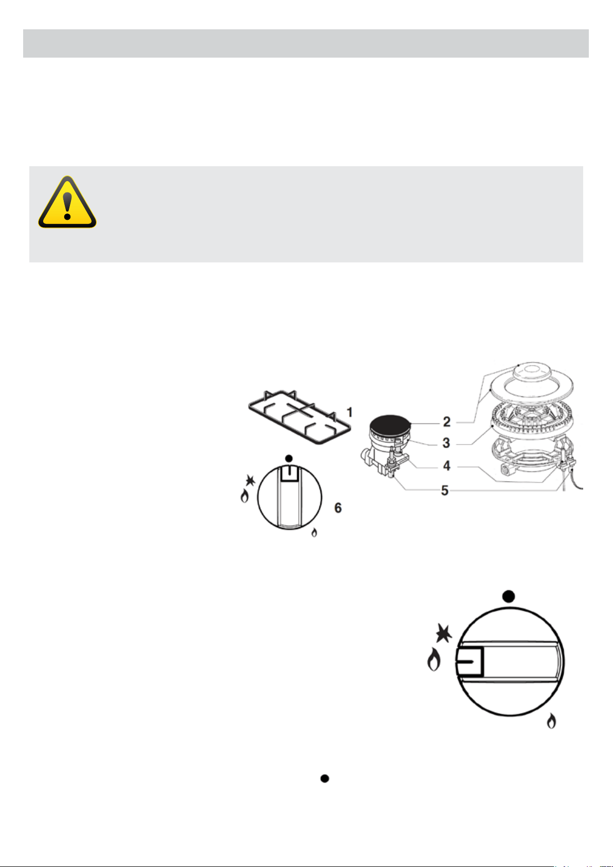
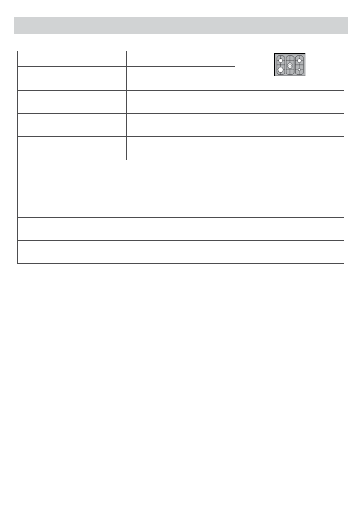
How to Use Burners of The Cooking Top
Description of the main parts of the appliance
WARNING
• Do not spray aerosols in the vicinity of this appliance while it is in operation.
• The appliance shall not be used as a space heater.
• Do not store ammable materials in the storage drawer.
• Use pots and pans with a at base.
• During cooking the appliance becomes very hot. Never touch any parts on the top or inside the oven
without protection from heat proof gloves.
1 = grid
2 = burner cap
3 = burner head
4 = spark plug
5 = safety valve (for models
equipped with a safety valve)
6 = knob for burner ignition and
adjustment
Ignition and Operation of the Burners
In order to ignite a burner, it is necessary to depress the knob while rotating
it anti clockwise, till the index is aligned with the position corresponding to
the maximum gas delivery (i.e. the large ame symbol). As far as the models
equipped with a safety valve are concerned, once the ame is lit hold the
knob depressed for about 3-4 seconds till the device keeps the burner
automatically lit.
If the burner fails to ignite wait one minute for the gas to dissipate before
attempting to reignite. At this moment it is possible to adjust the ame
intensity by rotating the knob anti clockwise from such maximum position to
the minimum one (i.e. the small ame symbol).
In order to turn the burner off, rotate the knob clockwise bringing the index
back to the position corresponding to the closure symbol
.
Page 16
4. User’s Guide
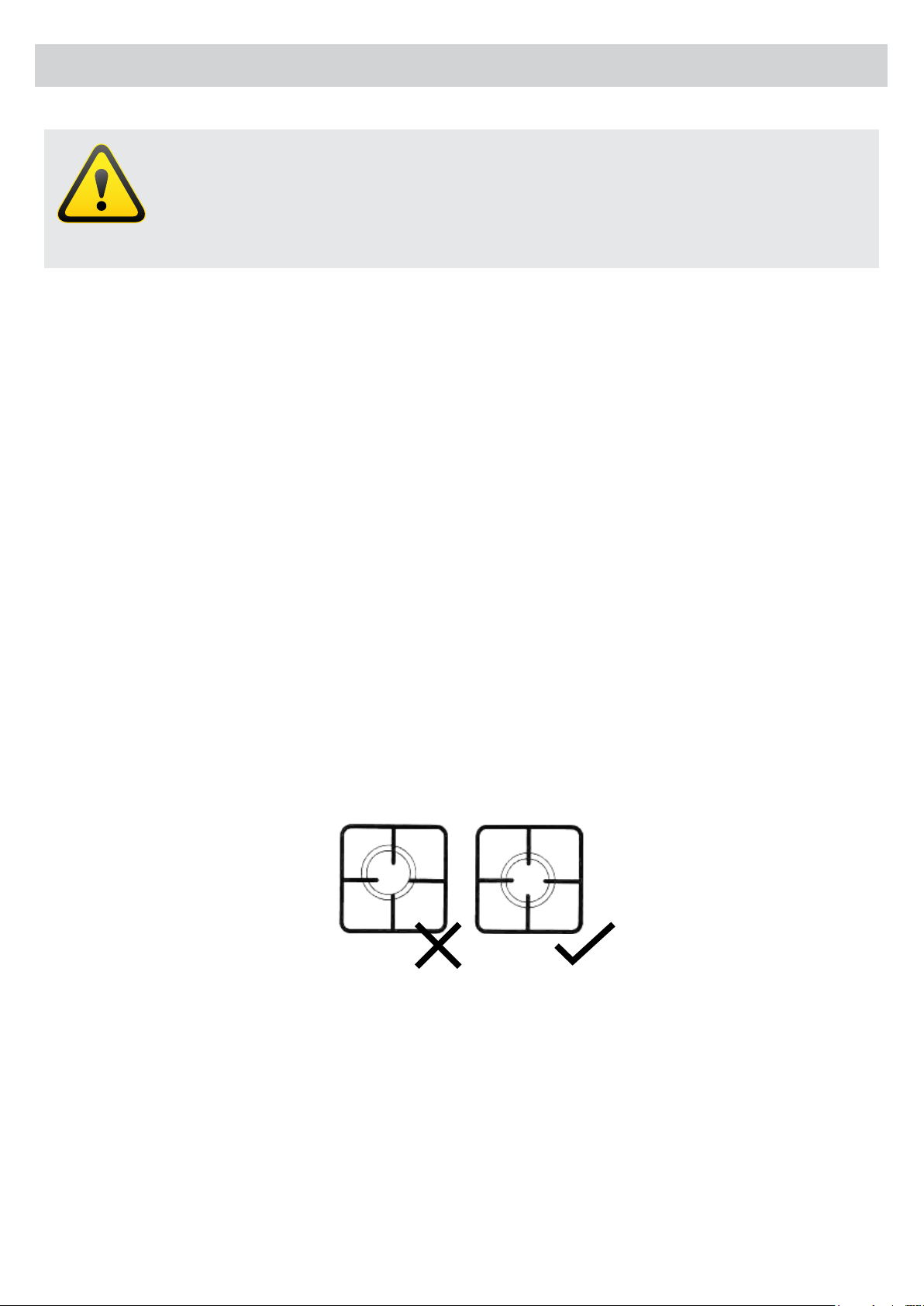
In the models with triple burner pay attention to these points:
Make sure the cover spreader is in the correct position, to guarantee good burning.
To ignite the burners proceed as follows:
• Push down the dial of a selected burner until you feel resistance and turn anti-clockwise
to the “large ame”position.
• Hold the dial until gas ignites
• Once ame ignites, release the dial and adjust ame size.
• To reduce the power to turn the knob to the “low position”, indicated by a small ame
.
• To switch off the burner, just turn the knob clockwise to the “off position”, indicated by a black circle in the
upper position of the panel
.
All models have a security system in the burners of the cooking top. If the gas supply is decient or if the ame
is extinguished accidentally, the gas circuit will be automatically closed.
To restart, it is necessary for user intervention. In this case and after verifying that it isn’t a gas supply problem,
wait at least one minute and repeat the lighting. To ignite this type of burner it’s necessary to maintain
pressure on the knob for 10 seconds. After this time, release the knob of the burner and function will reverse.
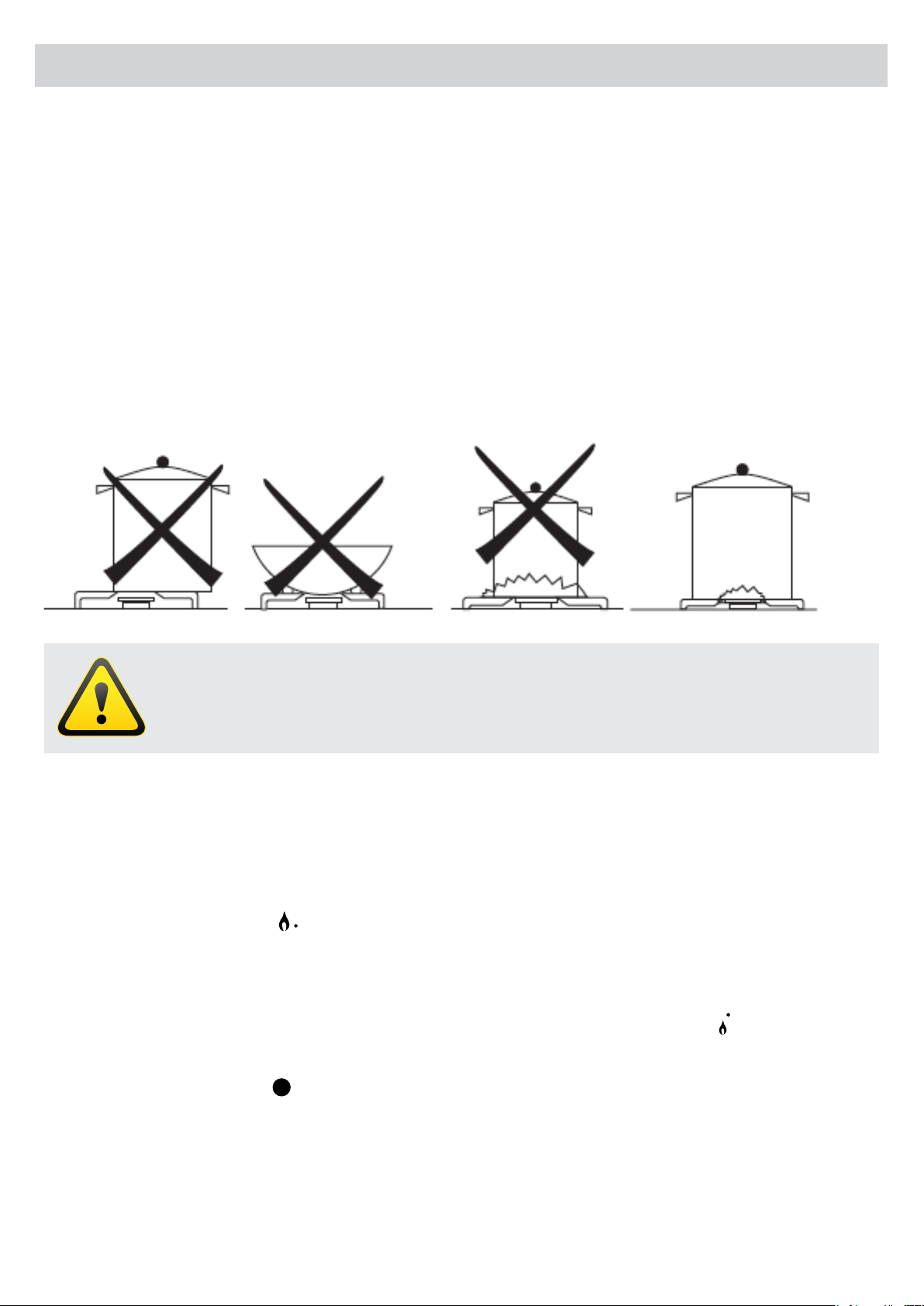
ATTENTION
• Only use cookware with at bottoms.
• Use cookware that does not exceed the edges of the work table.
Advice on the use of gas burners
For lower gas consumption and a better yield, use saucepans with a diameter suitable for the burners,
avoiding the ame coming up round the side of the saucepan. Use only at-bottomed pans. As soon as a
liquid starts to boil, turn the ame down to a level sufcient to maintain boiling.
During cooking, when using fats and oils, be very careful because if they overheat they could catch re.
If you use the burners properly, the consequence will be maximum efciency, thus saving energy.
The power of the burners is shown in the Tables section.
In order to obtain maximum efciency, you must choose pans according to the size of the burner.
See the Tables section.
Page 17
4. User’s Guide
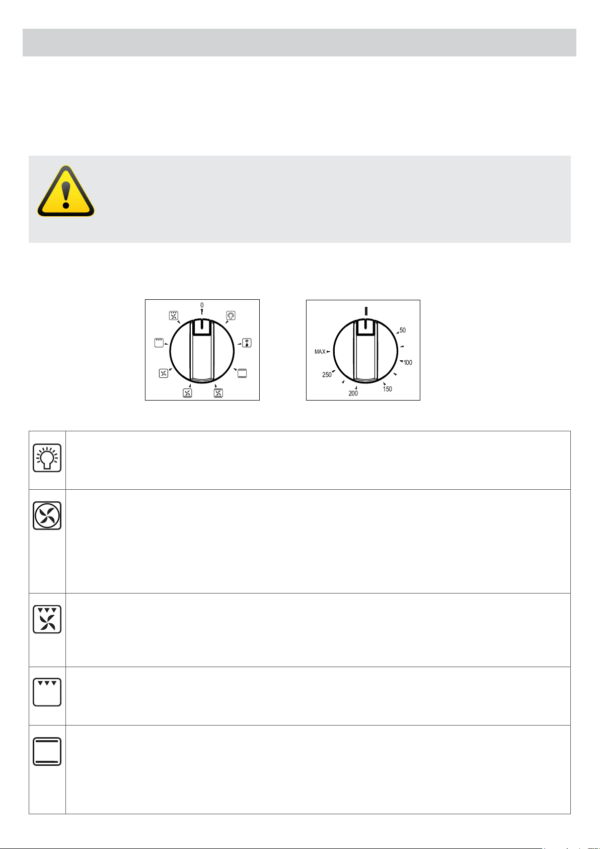
Oven light
In this position only the oven light is in operation. The light stays on when switching to different
heating elements.
Fan forced
The circular heating element and fan come into operation and the heat is spread evenly to all shelf
positions. Various types of food can be cooked on different shelves, naturally with the appropriate
cooking times. The oven must be preheated before food is placed inside. Fan mode provides
optimum results with: cakes, large quantities of foods and cooking various dishes simultaneously. To
operate, select Fan Forced function along with the temperature.
Fan & grill
Use of the Grill Element and Fan. Use for grilling meats, vegetables and poultry. Preheat oven, place
food on grill rack in baking tray and place in the middle of the oven. Other foods maybe cooked
underneath whilst grilling.
Grill
Grill Element. Use for toasting and melting cheese or browning. No longer than 5 minutes cooking
time. To operate, select Full Grill Function along with the temperature.
Conventional oven
The heat is provided from the top and bottom element. The oven must be preheated before food
is placed inside. Static cooking provides optimum results with: cakes, pizzas, bread and for gentle
slow cooking of casseroles. Characteristics of static cooking: heat provided from above and below,
cooking is possible only on middle shelf and should be centrally located in the oven.
ATTENTION
• Oven door must be closed for all cooking functions.
• The accessible parts of the cooker can become hot, if the oven or the grill is in operation.
• Do not let children get close to the appliance.
How to Use The Electric Multi-function Oven
Various cooking options can be selected by the use of switching to different elements, and adjusting the
temperature.
The oven door must be closed for all cooking methods
A
B
Figure A Function Selector Figure B Temperature Control
Page 18
Defrosting
The defrosting takes place in the same way as at room temperature, but with the advantage that it is
much more rapid. In this position only the fan is in operation.
Fan assisted
The outside ring of the top element and the bottom element and fan come into operation and the
heat is spread evenly to all shelf positions. Suitable for cooking pies and single layer baking. The
oven must be preheated before food is placed inside. To operate, select Fan Assisted function along
with the temperature.
Fan assisted with bottom element
Bake element.
Oven Light Use
To switch on the oven light turn the knob to the symbol .
Some models with electric oven light illuminates when you turn the handle of the oven, and stays on until you
turn off the oven.
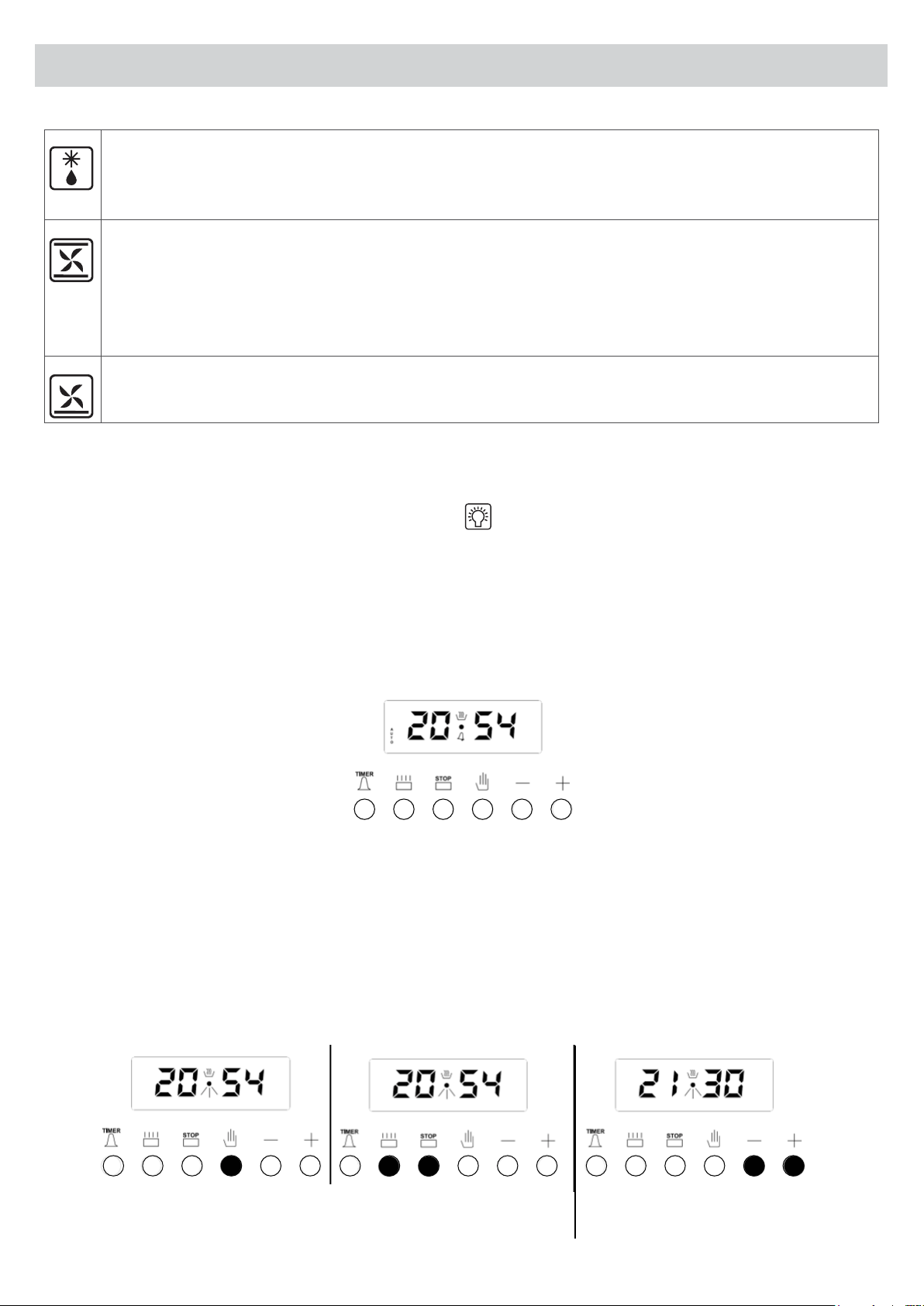
Electronic Programmer
4. User’s Guide
The electronic programmer enables your oven to get the food ready to serve at the desired time. The only
thing to be done is to program the cooking time and ready time. It can also be used as an alarm clock, where
you just adjust the amount of time after which it should remind you by a buzzer tone.
Time of day adjustment
This adjustment can only be made when no cooking program is in progress. Press the button and/or buttons
together for 5 seconds. Use the + and - to adjust the clock. Long presses of these buttons will result in faster changes.
1) Press the (4) button or the (2) and (3) buttons together.
2) Adjust the time using
the (+) or (–) buttons.
1 2 3 4
Page 19
4. User’s Guide
Adjusting the buzzer alarm
With this feature, you can program how much elapsed time you should be warned by a buzzer sound.
1) Switch into buzzer alarm
mode
2) Enter in the period of
time to be counted down
3) After a few seconds, screen
will return to clock mode
NOTE: Once programmed, the remaining time can be seen by pressing the (1) button once.
Cancelling the buzzer sound
1) Buzzer will sound after the
programmed amount of time elapses.
2) Press the (1) button to cancel.
Page 20
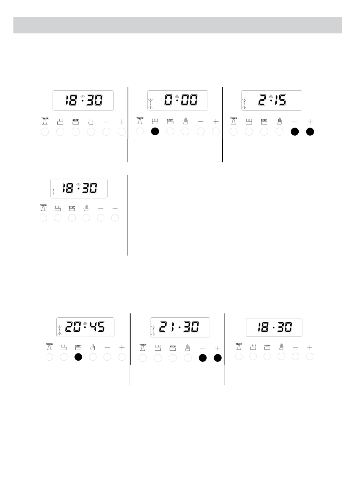
Automatic cooking program
If you want to start cooking immediately, you just have to adjust in the cooking time.
Example: We placed our food into the oven and want it to be cooked for 2 hours and 15 minutes.
1) Current time is 18:30. 2) Switch into cooking
time mode.
3) Adjust the cooking time
using the (+) or (-) buttons.
4) After a few seconds, the screen
will indicate that cooking has
started and show the current time
4. User’s Guide
Now, you have programmed your oven to cook the food
for 2 hours and 15 minutes.
Do not forget to bring the function and/or temperature
knobs of your oven to the appropriate position.
NOTE: You may cancel the automatic cooking mode any time by pressing the button and/or buttons together.
In the above example, cooking immediately started after programming in the cooking period. By pressing the
(3) button, you can see the ready time, ie. the time when the food will be ready to serve, and if you want, you
can also change it. In the example below, the ready time will be changed to 21:30.
1) Displayed is the ready time
18:30+2:15 = 20:45.
2) Set it to the desired time
by using the (+) or (-) buttons
3) In a few seconds, screen
switches to clock mode.
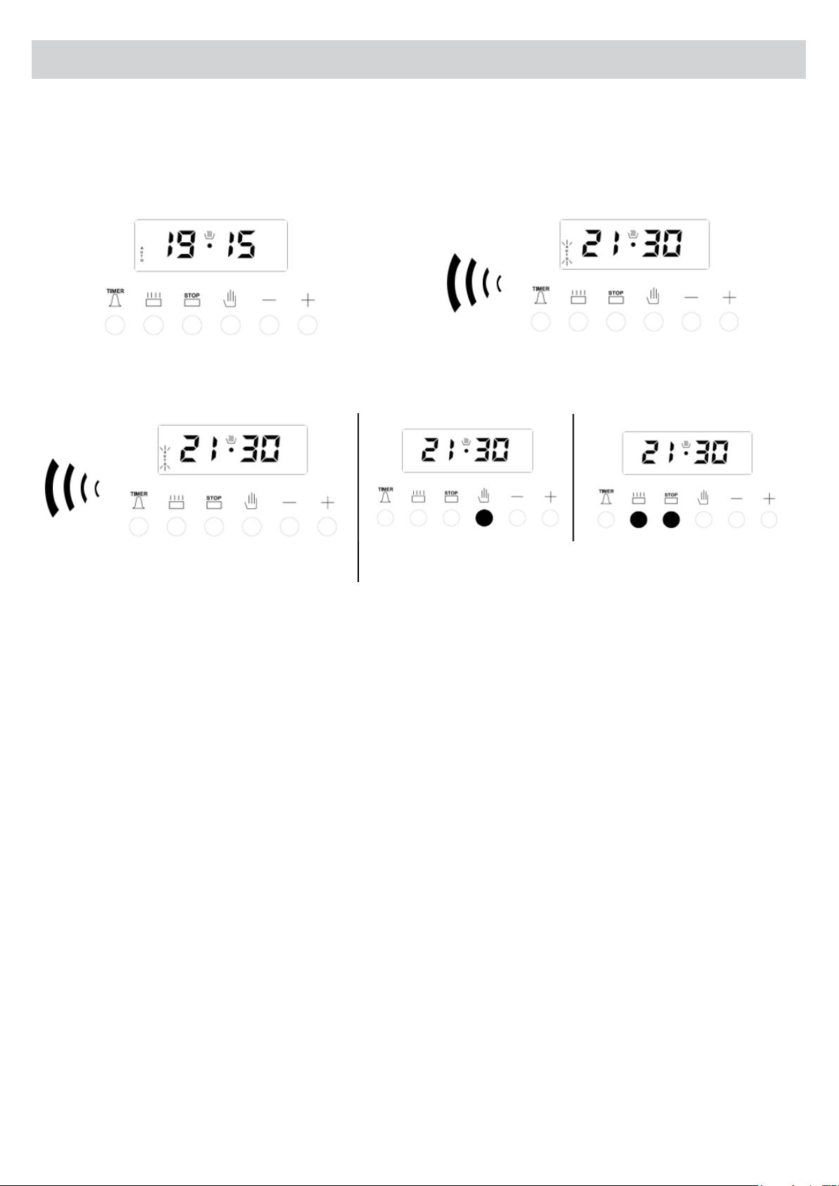
Page 21
4. User’s Guide
We now have programmed our oven to get the food ready at 21:30. Since the cooking time was pre-
programmed as 2 hours 15 minutes, your oven will start cooking at 19:15, so that the food is ready at 21:30.
Screen just when cooking starts Screen just when cooking ends
When automatic cooking is completed, a buzzer alarm is heard and will continue, if not stopped, for 7 minutes.
1) Switch your oven OFF
Turn the function selection and temperature
control “0” position (see gure A and B).
2) Reset the timer.
NOTE: Your oven will be inoperative until you reset the timer.
In the example shown, cooking time has been programmed rst, the ready time was calculated automatically
and was edited by us. It is also possible rst to program the ready time, in that case the cooking time will be
calculated automatically and should be edited thereafter.
Buzzer volume adjustment
You may adjust the buzzer tone of the timer in the following way:
1. Pressing and holding the (–) button, you can hear the current buzzer tone. Releasing and pressing again
will switch to the next tone (3 different tones available)
2. The buzzer tone will be set to the last adjusted tone.
NOTE: As a factory setting, the buzzer volume is set to the high tone. In case of a long power loss, the set
buzzer tone will be this default.

Page 22
4. User’s Guide
General Remarks
• Between 10pm and 6am the display intensity dims automatically.
• If not deactivated as per the following instructions, the acoustic signal is cut off after 2 minutes.
• Any programming described hereunder is activated after approx. 4 seconds from its setting up.
• 23 hours and 59 minutes is the maximum time allowed for programming the oven.
• If the supply voltage fails, all the programmed settings are erased. When the supply voltage returns, the
display blinks and shows 0.00. Set the actual time and the programme again to reset operation.
Automatic Operation
The oven can be programmed to switch on and off automatically.
To do this proceed as follows:
1. Select the required cooking function and temperature using the function selector and the thermostat dial.
2. Press button (2) and set the cooking time by pressing buttons (-) and (+) within the next 4 seconds.
3. Press button (3) and set the end of the cooking time in the same way.
The actual time reappears and pilot light (AUTO) remains ON, when the cooking process starts, pilot light (A)
will remain on. The cooking time left can be controlled by pressing button (2), or the time can be changed by
repeating the same procedure.
Reset the cooking time to 0.00 to erase the preset programme, and when the actual time reappears, press
button (4) to reset the manual function. Once the cooking process is over the acoustic signal goes off and
the oven is automatically switched off. Press one of the buttons from (1) to (4) to return the programmer to the
manual function.
Semi-automatic Operation
The oven can be programmed to switch off automatically.
To do this proceed as follows:
1. Select the required function and temperature using the cooking function selector and the thermostat dial.
2. Press button (2) and set the cooking time by pressing buttons (-) and (+) within the next 4 seconds. The
actual time reappears and pilot lights (A) and (AUTO) remain ON.
The cooking time left can be checked by pressing button (2), or the time can be changed by repeating the same
procedure.
To erase the pre-set programme, reset the cooking time to 0.00, when the actual time reappears, press button (4)
to reset to manual function.
Once the cooking programme is complete, the acoustic signal will sound and the oven is automatically switched
off. Press one of the buttons from (1) to (4) to switch off the acoustic signal. Press button (4) to return the
programmer to the manual function.
Page 23
4. User’s Guide
Minute Minder
When this device is used as a simple minute minder, press button (1) and programme the required time
by pressing buttons (-) and (+) within the next 4 seconds: the actual time reappears and the symbol (B)
is activated. Press one of the buttons from 1 to 4 to disconnect the acoustic signaller. Also symbol (B) is
deactivated.
Manual Operation
The oven may be used manually without any programming. Press button (4) for the manual operation (“AUTO”
will disappear).
Recommendations for Using the Oven and the Grill
The accessible parts of the cooker could be hot, if the oven or the grill is in operation.
Do not let children close to the appliance.
Do not let children sit down or play with the oven door. Do not use the drop down door
as a stool to reach above cabinets.
WARNING
Never use the food warmer drawer at the bottom of the cooker to store ammable
substances or liquids that cannot withstand heat such as: wood, paper, spray cans, rags, etc.

Page 24
4. User’s Guide
• Pre-heat the oven until it reaches the required temperature, before you
put the food into the oven.
• Never use low-edged trays as a baking-pan for roasts in order to reduce
soiling of the walls of the oven, thus preventing fat splashes, sauce
burning and smoke production.
• If grease falls down onto the oven heating element it could ignite.
• Use high-edged cookware, preferably terracotta containers, put on the
grate at about half the height of the oven.
• When the food is directly on the wire rack, you must use the drip tray for
collecting.
• Never use the oven without the door seal.
During the functioning of the oven and of the grill, the oven door must rest completely closed.
It is advisable to:
• Place the cooking tray on the middle level of the oven.
• Avoid opening the door during cooking, since the temperature changes will spoil your cooking and increase
energy consumption.
Page 25
5. Instructions for Maintenance and Cleaning
General Cleaning
• Adequate maintenance and cleaning will prolong the life of the appliance, as well as ensure trouble-free
service.
• The cooker must be washed with warm water, using a damp sponge and ordinary detergent.
• Never use scouring powder, steel wool or acids to clean the cooker.
• The stainless steel parts should be washed, after use, with water and dried with a soft cloth. If the spots still
persist, it is necessary to use a non-abrasive detergent or warm vinegar.
• The glass of the oven’s door should be washed with warm water and a nylon pad soaked in ordinary
detergent.
• Avoid scrubbing the front panel, because this will erase the designs stencilled over each knob.
• The enamelled grids of the knob can be washed in the dishwasher.
• The cooker must not be cleaned with vapour equipment (eg. steam cleaners).
• After a possible grid removal for cleaning, we recommend to verify the presence of such rubber pads and to
put the grids back in their stable and centred correct position
WARNING
• Servicing should be carried out only by authorised personnel.
• Before maintenance or cleaning your cooker, switch off the circuit breaker, turn off the
isolating gas valve or the gas mains and allow the cooker to cool down.
Cleaning the Burners
• The burners should be cleaned with soapy warm water and well rinsed and dried.
• Ensure they are completely dry before using.
Page 26
5. Instructions for Maintenance and Cleaning
Oven Cleaning
The oven should be washed with warm water and a nylon pad soaked in ordinary detergent.
The oven is “Easy to Clean“ enamel, no need for abrasive detergent or cleaning cloths for cleaning.
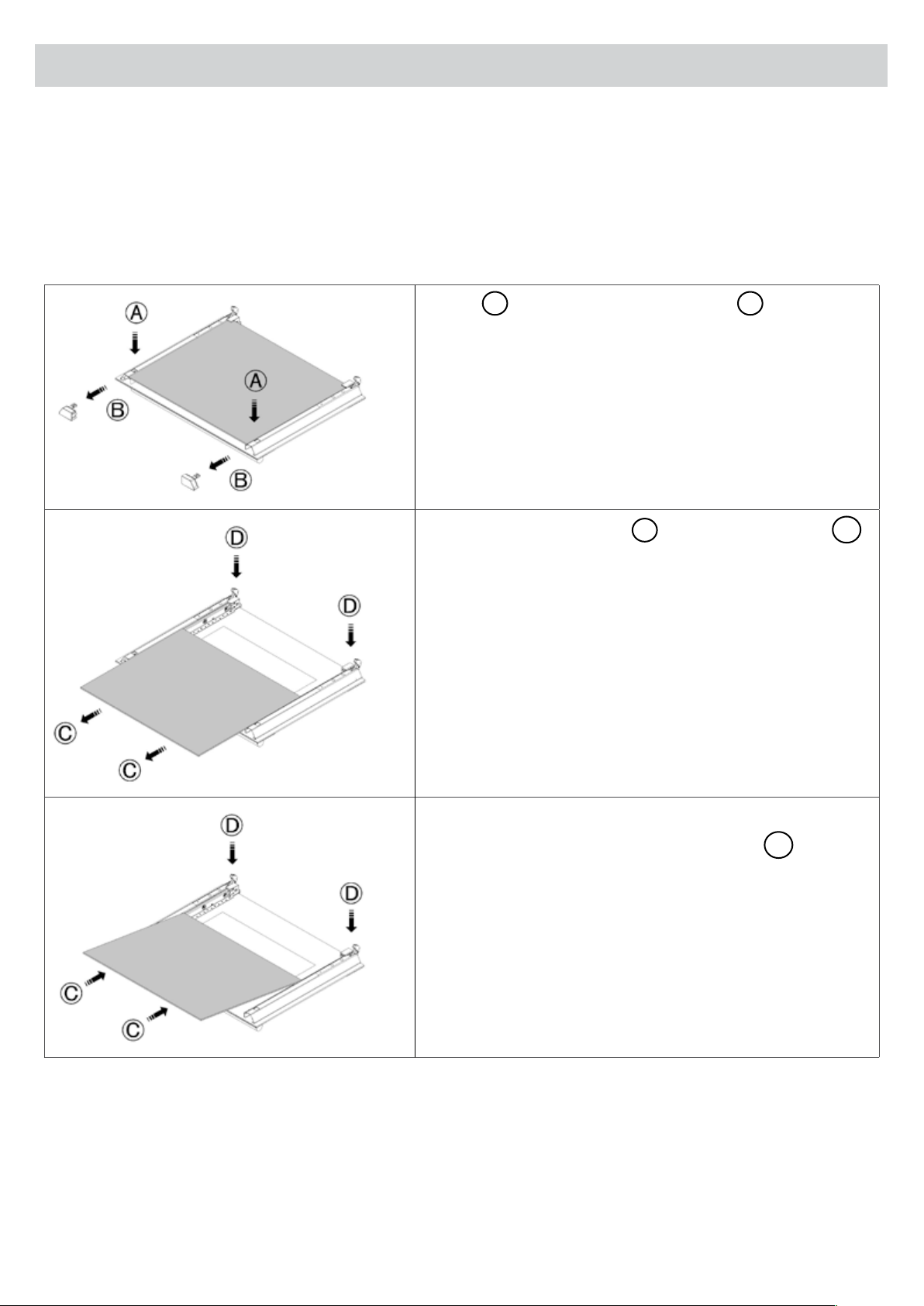
How to remove the interior glass on the oven’s door for cleaning:
• Press
A
, and remove the interior tops
B
.
• Release the interior glass
C
, from the interior tops
D
.
• Remove the interior glass.
• Clean the glass with warm water and a nylon pad soaked
in ordinary detergent.
• Place the glass in the supports.
• Slide in the glass until engages the groove
D
of the
interior tops.
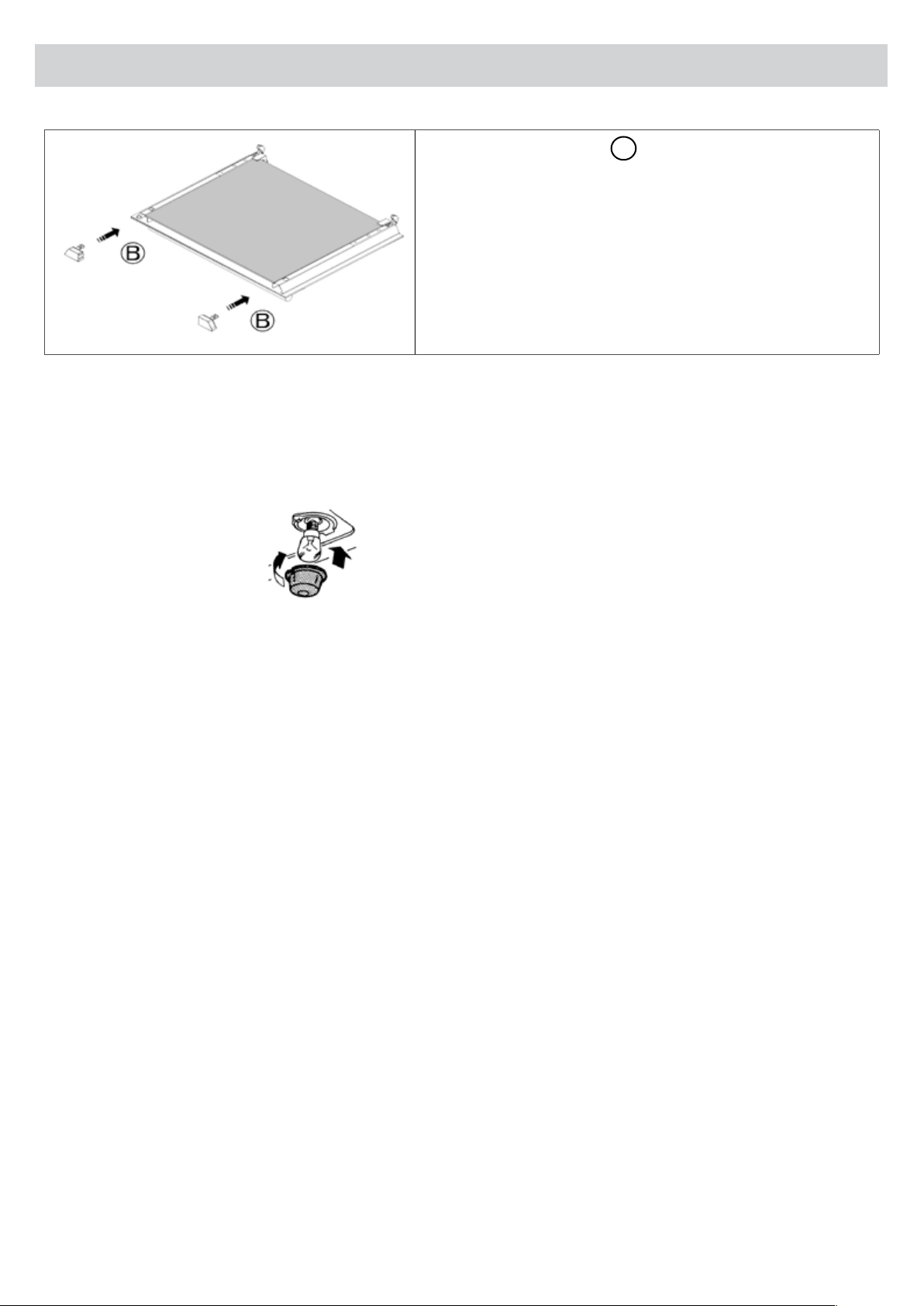
Page 27
5. Instructions for Maintenance and Cleaning
• Insert the interior tops
B
.
Replacing The Oven Bulb
Once the appliance has been electrically disconnected, unscrew the glass protection cap and the bulb,
replacing it with another one suitable for high temperatures (300ºC) having the following characteristics:
Voltage: 220 – 240 V
Power: 15 / 25 W
Socket: E14
Reassemble the glass cup and reconnect the appliance.
Page 28
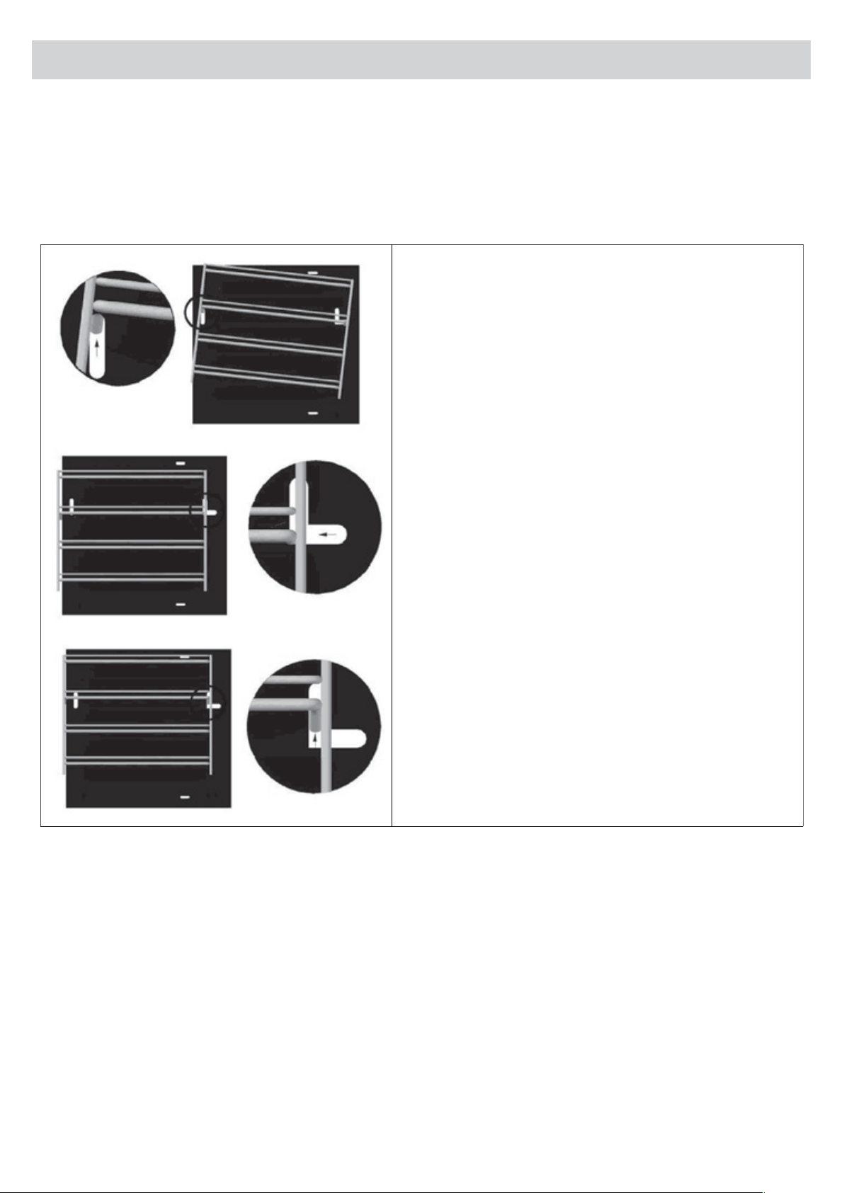
5. Instructions for Maintenance and Cleaning
Removing the Side Racks of the Oven
• To facilitate cleaning, the chrome side racks can be removed.
• Follow the instructions (1) to (3) for removal.
• To re-install follow the instructions in reverse from (3) to (1).
1. Raise the side rack vertically and remove the pin in
the groove on the front side of the oven
2. Move the grid in the direction indicated so that
moves into the slot along the coast of the oven.
3. Move the grid in the direction indicated so that it
moves into the slot along the coast of the oven.
Vertical lift and remove the pin in the groove in the
back side of the oven.
The stainless steel runners that support the enamelled trays can be removed and placed on any of the three
levels of the side racks.
Page 29
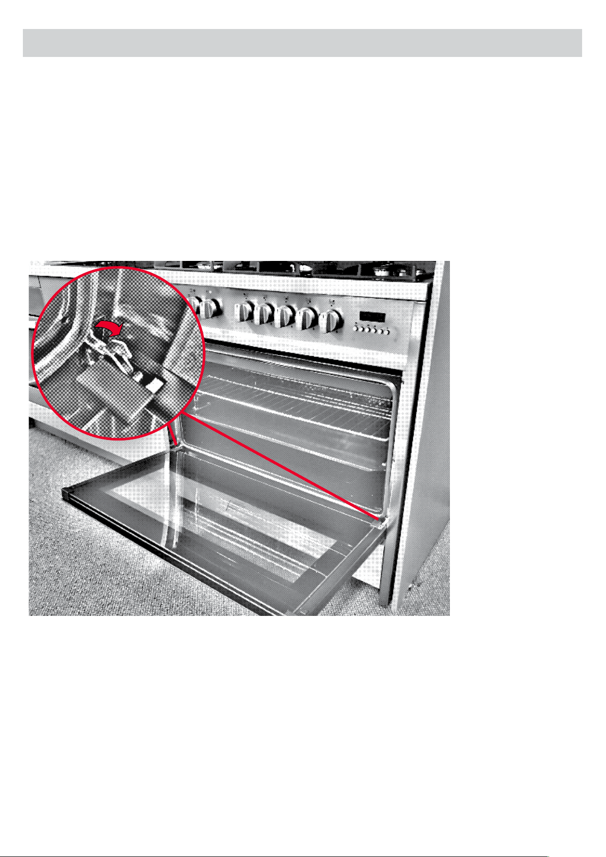
Remove the Oven Door for Cleaning
For complete cleaning, we advise removing the door as follows:
• Set the door wide open.
• Turn the brackets of the lower hinges upwards until hooking the upper hinges.
• Set the door ajar, then lift lightly to remove the lower hinges from the slots.
• Remove the door and the two upper hinges from their seats.
• Clean the door and reassemble reversing the above mentioned steps.
5. Instructions for Maintenance and Cleaning

Page 30
6. Control of The Product
The producer certies that this appliance has undergone the following verications:
• Electric unit operation
• Dielectric rigidity
• Earthing continuity
• Operation with one type of gas
• Leak control
• Operation of the safety valves
• Aesthetic control
Page 31
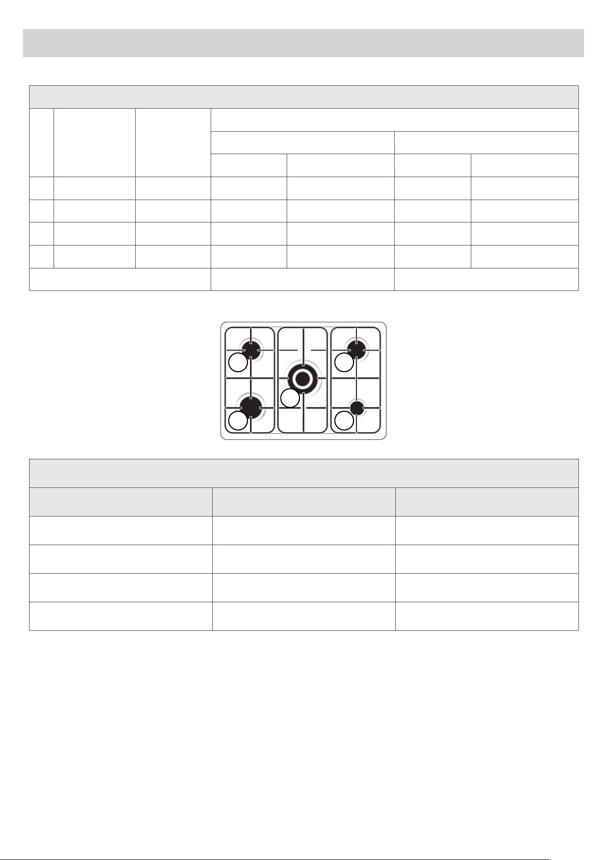
7. Tables
Table 2 Recommended diameters, of cooking pots with at bases
Burners Minimum (cm) Maximum (cm)
Auxiliary diameter 42mm 10 16
Semi Rapid diameter 62mm 15 22
Rapid diameter 92mm 22 28
Wok diameter 130mm 24 30
Table 1 Burner and Injector Characteristic
n˚ Burner
By pass
(mm)
Consumption (*)
ULPG Natural gas
Output MJ/h Main Injector (mm) Output MJ/h Main Injector (mm)
1 Rapid 0.90 11 0.89 12 1.55
2 Semi Rapid 0.58 6 0.68 7.2 1.20
3 Auxiliary 0.48 3.8 0.53 4.0 0.90
4 Wok 1.06 13 1.00 14 1.65
Test point pressure 2.75 kPa 1,0 kPa
1
2 2
3
4
Page 32
8. Technical Characteristics
Burners
Electric
Auxiliary - 1
Semi-rapid - 2
Rapid - 1
Wok - 1
Oven 4000 E
Grill 2800 E
Circular Resistance 4600 E
Oven volume (L) 121
EE table (%) 65
Maximum electric power (W) 4707
Electric supply (V) 230-240V
Maximum Intensity (A) 19.6
Electric cable (HO5 PR - F) 3G 4
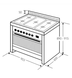
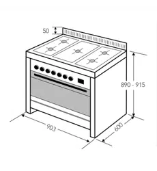
Dimensions Cooker: W x D x H (mm) 903 x 615 x 940
Dimensions Package: W x D x H (mm) 960 x 690 x 1005
Weight: Net/Gross (kg) 82/88
Page 33
9. Troubleshooting
Some minor faults can be xed by referring to the instructions in the table below. Before calling the customer
service centre, check the following points.
Problem Reason Action
1. The appliance does not work Break in power supply Check the household fuse box; if
there is a blown fuse replace it.
2. The program display keeps
ashing
The appliance was disconnected
from the mains or there was a
temporary power cut
Set the current time (see
“Electronic Programmer”)
3. The oven light does not work The bulb is loose or damaged. Tighten up or replace the
blown bulb (see “Cleaning and
Maintenance”)
Gas Burners
Problem Action
Yellow tipping of the hob burner ame Contact the customer service centre.
Sooting up of cooking utensils
Burners not igniting properly
Burners failing to remain alight
Burners extinguished when opening oven door
Gas valves are difcult to turn
In Case of Emergency
In the event of an emergency, you should:
• Switch off all working units of the oven
• Disconnect the mains plug
• Call the service centre

Page 34
9. Troubleshooting
Service
In the event that the failure is not due to the faults mentioned in Troubleshooting, contact the customer
service centre.
In Australia,
Customer Service 1300 829 066
In New Zealand,
Customer Service 0800 200 510
Lodging an Online Service Request
In the event that failure is not due the reason/s in the trouble shooting section, you can lodge an online
Service Request. To lodge Service Request, visit our website www.scandiumappliances.com.au/service-request
and click on the link and complete the service request form.
A service request will require the following information:
• The purchase date
• The model number
• The serial number or batch number (is on either the sticker on the bottom edge of the door or back of oven
or inside the rangehood).
• A copy of the purchase receipt (without a receipt your service request cannot be processed).
Faulty Installation
It is not the responsibility of Scandium to rectify any incorrect installations. A service call out fee will be
charged for any Scandium technician that attends a call, whereby it is established that the fault is due to an
incorrect installation or non-manufacturing fault. Should the appliance be installed in such a way that the
service agent is unable to gain access to the appliance, the person/s who own the premises or the property
where the appliance resides — will be responsible to provide access to the appliance at their expense.
Page 35
10. Disclaimer
Under our policy of continuous product development, product specications may change without notice.
Prospective purchasers should therefore check with the retailer to ensure this publication correctly describes
the products being offered for sale. All information supplied is to be used for general reference purposes
only and is on the understanding that Scandium will not be liable for any loss, liability or damage of whatever
kind arising as a result of any reliance upon such information. All pictures used in the guide are for illustrative
purposes only.
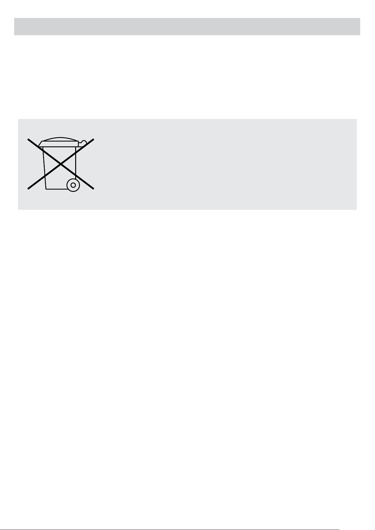
The symbol on the product or its packaging indicates that it cannot be treated
as normal household waste. Take this product to your nearest electrical and
electronic equipment waste point for recycling. By correctly disposing of this
product, you will be helping to prevent potentially negative consequences
for the environment and public health, which could arise if this product is
not handled in the appropriate way. For more details about the recycling of
this product please contact the authorities of your city or town, your local
household waste service or the store where you purchased the product.

V1090817
Distributed by Axis Group International Pty Ltd.
ACN 124 141 322
Australia 8/3-4 Anzed Court, Mulgrave 3170 Victoria. Phone 1300 881 693
Email [email protected] Web www.scandiumappliances.com.au
New Zealand 5 Tolich Place, Henderson, Auckland 0610. Phone 0800 200 510
Email [email protected] Web www.parex.co.nz