Loading ...
Loading ...
Loading ...
Rinnai 20 EHPA_A Heat Pump OIM
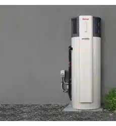
Electrical access is via a 20 mm hole beneath the element
cover for mounting with an approved weatherproof electrical
conduit nipple.
For entry to the element cover remove the two xing screws.
Connect all ACTIVE and NEUTRAL wires in accordance with
the wiring diagram which is also included at the rear of the
element access cover.
Ensure the incoming EARTH wire is securely xed to the earth
post provided on the heater case.
Inspect and ensure that all wiring links are secure prior to
xing the access cover and turning the POWER ON.
To ensure the over-temperature and energy cut-out is set,
press the (red) ‘reset’ button on the Thermostat
NEUTRAL
EARTH
CONTROLLER
CONTROLLER
CONT-
ROLLER
NEUTRAL
Electrical
Connections
Access
IMPORTANT
This appliance MUST NOT be connected via a
switchable or a solar (photovoltaic - PV) power
supply without manufacturer consultation.
The switching of the supplies will place the water
heater into a re-start cycle which reduces the
available heating time and may result in a lack
of hot water.
It is recommended this appliance is connected to
either a 24 hour continuous tari or an extended
o-peak power supply (minimum 16 hours per
day, noting that the minimum required running
time is governed by hot water demand and the
climate zone.
If this appliance is replacing an electric water
heater with a capacity of 250 litres (or greater),
then a connection to a 24 hour continuous tari
supply is recommended.
Disconnect all power prior to installation and commissioning.
This appliance is designed for single phase 240 Volts, AC
mains electrical operation.
FILLING THE SYSTEM
Open hot water tap at sink.
Open the stop cock in the cold water main supply line. Allow
the system to ll and the air to bleed through the tap.
Turn off the hot tap at the sink when water ows freely without
any air bubbles or air bursts.
Bleed any remaining air from the PTR valve.
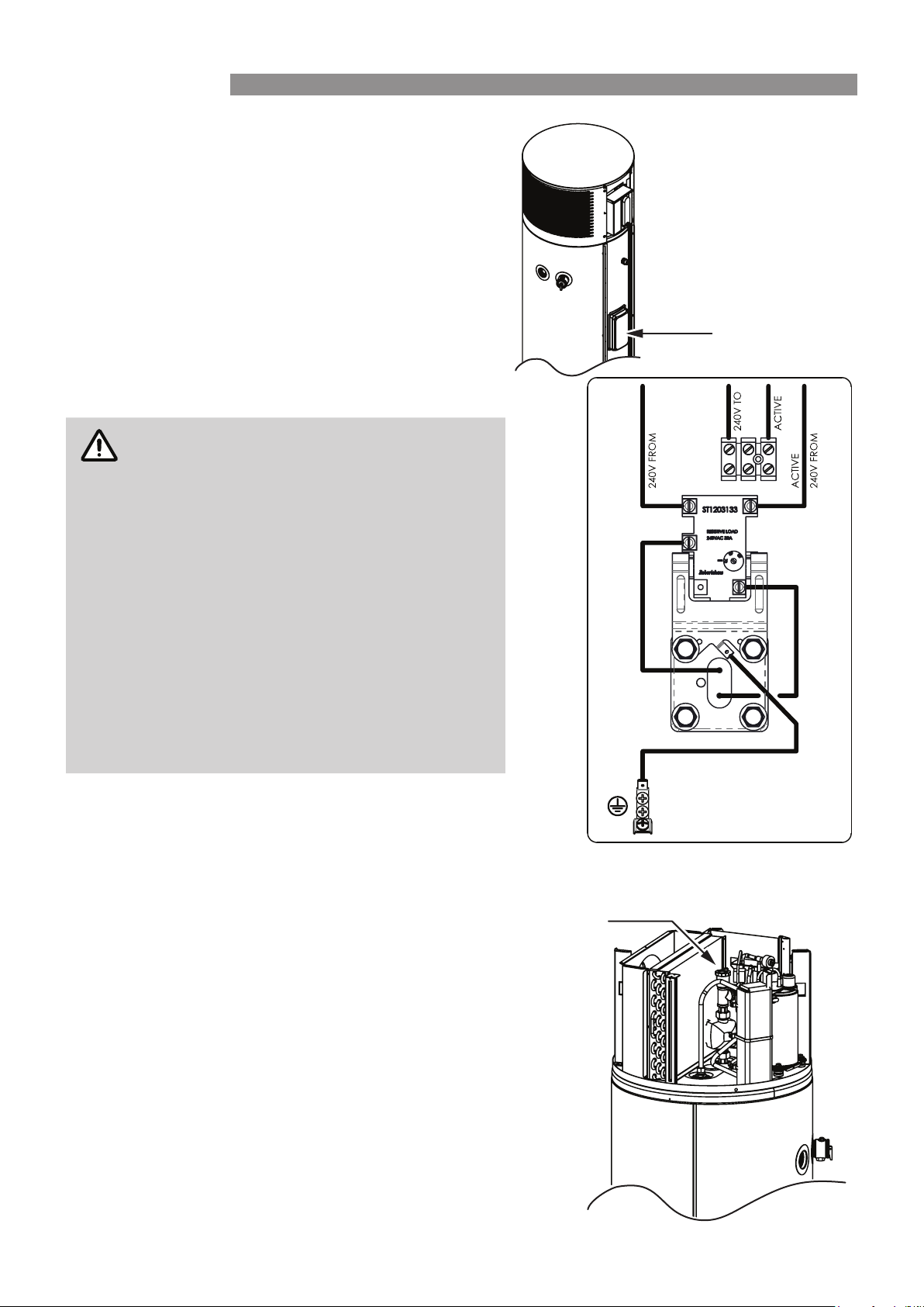
An automatic air bleed valve is tted on top of the circulation
pump of the heat pump module:
Turn on power to the heat pump unit and wait 30 seconds for
the circulation pump to turn on. Any remaining air will be bled
from the automatic air vent.
If leaks are detected turn off power to the heat pump, repair
any leaks and repeat the lling process to remove any air.
If no leaks are detected water heating can commence. The
heat pump will start up after the 2 minute protection time.
Automatic Air
Bleed Valve
INSTALLATION
Loading ...
Loading ...
Loading ...