Loading ...
Loading ...
Loading ...
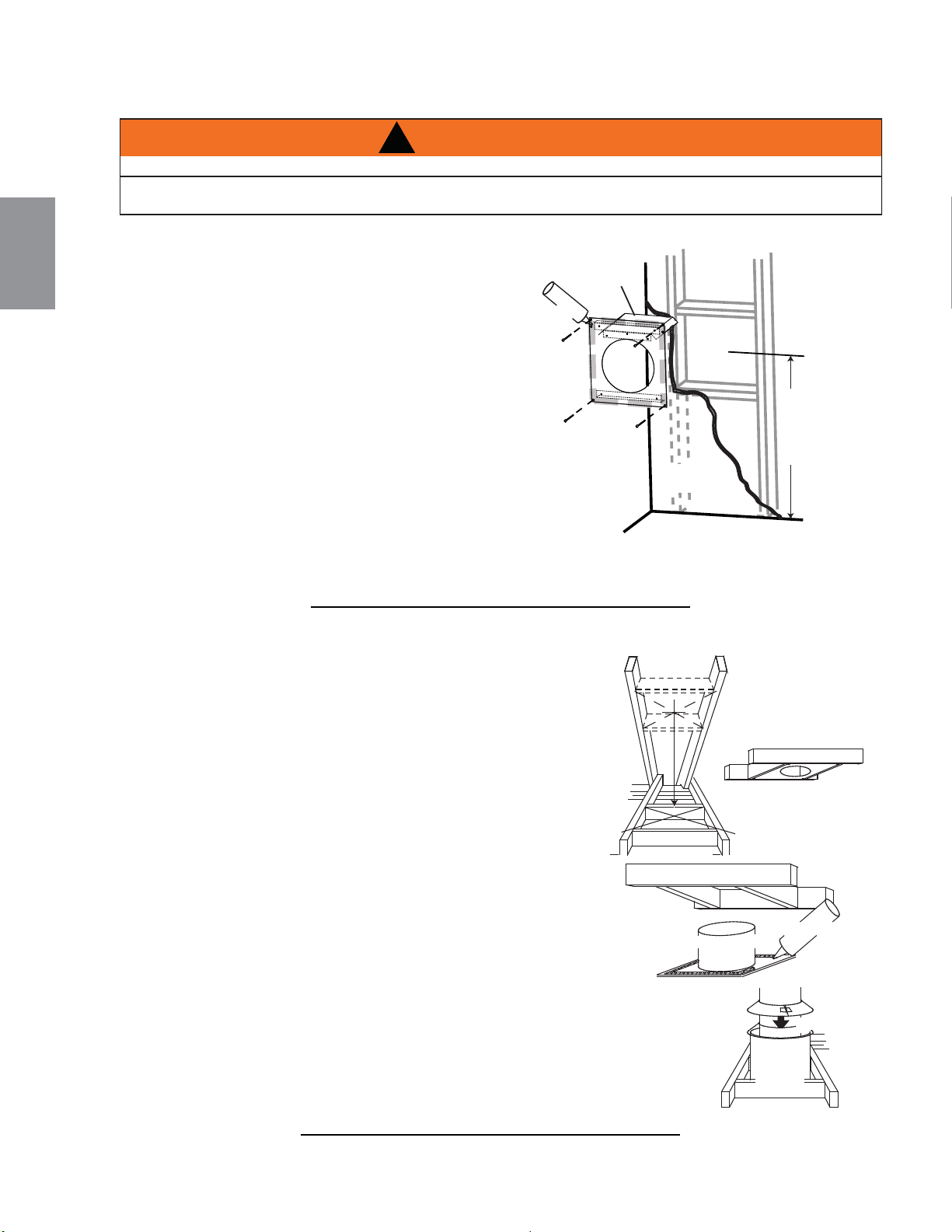
Cette confi guration s’applique lorsque le conduit
d’évent traverse un mur extérieur. Une fois que vous aurez
déterminé la hauteur exacte pour l’emplacement de la
terminaison, découpez et charpentez
une ouverture dans le mur extérieur (comme
illustré) pour permettre l’installation de l’espaceur
coupe-feu. Avant de continuer, placez l’espaceur
coupe-feu dans l’ouverture pour vous assurer que les
supports sur la surface arrière soient placés contre la
face intérieure de la pièce de charpente horizontale.
L’écran protecteur peut-être taillé pour des murs
combustibles qui ont moins de 8 1/2” (215,9mm) de profond,
mais doit se prolonger sur toute la profondeur du mur
combustible.
A. Appliquez un joint de calfeutrage (non fourni) tout autour de la
bordure de la face intérieure de l’espaceur coupe-feu, installez
l’espaceur coupe-feu contre le trou et fi xez à l’aide des quatre
vis (fournies dans le sac de votre manuel).
B. Une fois que le conduit d’évent est en place, appliquez du scellant à haute température W573-0007
(non fourni) entre le conduit d’évent et l’espaceur coupe-feu.
20.2A
!
AVERTISSEMENT
L’ESPACEUR COUPE-FEU DOIT ÊTRE INSTALLÉ AVEC L’ÉCRAN PROTECTEUR ORIENTÉ VERS LE HAUT.
LA TERMINAISON NE DOIT PAS ÊTRE ENCHÂSSÉE DANS LE MUR OU LE REVÊTEMENT EXTÉRIEUR
PLUS QUE L’ÉPAISSEUR DE LA BRIDE DE LA PLAQUE DE MONTAGE.
DÉTERMINEZ
LA BONNE
HAUTEUR
CALFEUTRAGE
ESPACEUR
COUPE-FEU
PROTECTEUR
DE CONDUIT
D’ÉVACUATION
MATÉRIAU
DE FINITION
This application occurs when venting through a roof. Installation kits for
various roof pitches are available from your authorized dealer / distributor. See
accessories to order specifi c kits required.
A. Determine the air terminal location, cut and frame a square opening as
illustrated in the ceiling and the roof to provide the minimum 1“ (25mm)
clearance between the vent pipe and any combustible material. Try to center
the vent pipe location midway between two joists to prevent having to cut
them. Use a plumb bob to line up the center of the openings. A vent pipe
shield will prevent any materials such as insulation, from fi lling up the 1”
(25mm) air space around the pipe. Nail headers between the joist for
extra support.
B. Apply a bead of caulking (not supplied) to the framework or to the Wolf
Steel vent pipe shield plate or equivalent (in the case of a fi nished ceiling),
and secure over the opening in the ceiling. A fi restop must be placed on the
bottom of each framed opening in a roof or ceiling that the venting system passes
through. Apply a bead of caulking all around and place a fi restop spacer over
the vent shield to restrict cold air from being drawn into the room or around the
fi replace. Ensure that both spacer and shield maintain the required clearance to
combustibles. Once the vent pipe is installed in its fi nal position, apply sealant between the
pipe and the fi restop assembly.
C. In the attic, slide the vent pipe collar down to cover up the open end of the shield and
tighten. This will prevent any materials, such as insulation, from fi lling up the 1” (25mm) air
space around the pipe.
21.1
CAULKING
VENT PIPE
SHIELD
FIRESTOP
UNDERSIDE OF
JOIST
VENT
PIPE
COLLAR
VENT
PIPE
SHIELD
88
W415-1399 / 10.01.14
FR
4.1.1 INSTALLATION HORIZONTALE
4.1.2 INSTALLATION VERTICALE
Loading ...
Loading ...
Loading ...